Download user manual - Flymaster
Transcript
M1 User manual Version 1.0 M1InstallationManual 2010FLYMASTERAvionicsLtd. R. Comendador Rainho, 192 - Apartado 118 3701-910 S. João da Madeira Portugal Tel: + 351 256 880 568 Fax: + 351 256 880 551 All rights reserved. Except as expressly provided herein, no part of this manual may be reproduced, copied, transmitted, disseminated, downloaded or stored in any storage medium, for any purpose without the express prior written consent of FLYMASTER Avionics Lda. herein FLYMASTER avionics. FLYMASTER Avionics hereby grants permission to download a copy of this manual onto a hard drive or other electronic storage medium to be viewed and to print a copy of this manual or of any revision hereto, provided that such electronic or printed copy of this manual must contain the complete text of this copyright notice and provided further that any unauthorized commercial distribution of this manual or any revision hereto is strictly prohibited. Information in this document is subject to change without notice. FLYMASTER Avionics reserves the right to change or improve its products and to make changes in the content without obligation to notify any person or organization of such changes or improvements. Visit the FLYMASTER Avionics website (www.flymaster-avionics.com) for current updates and supplemental information concerning the use and operation of this and other FLYMASTER Avionics products. Version 1.0 Warning It is the sole responsibility of the pilot to operate the aircraft in a safe manner, maintain full surveillance of all flying conditions at all times, and not become distracted by the FlymasterM1. Flymaster Avionics is not responsible for any damages resulting from incorrect or no data provided by the Flymaster M1. Flight safety is the sole responsibility of the pilot. It is unsafe to operate the FlymasterM1 while in the air. Failure by the pilot equipped with a FlymasterM1 to pay full attention to the aircraft and flying conditions while flying could result in accident with property damage and/or personal injury. 3 Version 1.0 M1InstallationManual Table of contents Table of contents 1. Introduction.................................................................................................................5 2.Getting Started..............................................................................................................5 2.1.M1 Keys...............................................................................................................................6 2.2.Switching M1 On and Off...................................................................................................6 3.Flight Data.....................................................................................................................7 4.Settings Menu................................................................................................................9 4.1.Date and Time...................................................................................................................10 4.2.Reset Counter....................................................................................................................10 4.3.Temperature Offset...........................................................................................................10 4.4.Stroke Number...................................................................................................................10 4.5.Fuel Settings......................................................................................................................11 4.5.1.Tank Calibration......................................................................................................................11 4.5.2.Sensor Calibration...................................................................................................................11 4.5.3.Tank Empty.............................................................................................................................11 4.5.4.Fuel Units.................................................................................................................................12 4.5.5.Average Fuel Consumption.....................................................................................................12 5.Fuel Sensor Installation Procedure...........................................................................12 5.1.Fuel Sensor Position.........................................................................................................13 5.2.Fuel Sensor .Cutting Procedure........................................................................................14 5.2.1.Deciding Sensor Length .........................................................................................................14 5.2.2.Cutting the Metallic Tube........................................................................................................16 5.3.Sensor Calibration Procedure..........................................................................................18 5.4.Tank calibration................................................................................................................20 6.Temperature Sensor Installation..............................................................................22 7.RPM Sensor Installation............................................................................................23 8.Updating firmware.....................................................................................................24 Version 1.0 4 1. Introduction Thank you for choosing FLYMASTER M1. If you have any questions or comments regarding the use of our instruments you can visit our website or contact our Support Department ([email protected]). This manual covers Firmware versions up to 1.2. If have a more recent version of firmware some of the features may not be covered. 2. Getting Started Fully charge battery before using FLYMASTERM1 for the first time. The battery may be charged by either connecting the M1 USB connector to the wall socket charger or USB cable. M1 connector can be found on the left side of the M1 (see Figure 1). Figure 1- Battery charger connection The charging process is automatic. The end of the charging process is indicated by the screen message “Charging Complete”. Usually, completely charging the M1 battery takes approximately 7 hours. M1 uses a Lithium-ion polymer battery, which is not prone to “memory effect”. Therefore the battery does not need to be totally discharged before recharging. In fact, in order to avoid battery degradation total battery discharge should be avoided. 5 Version 1.0 M1InstallationManual 2.1. M1Keys Figure 2 - FLYMASTERM1Keyboard Three keys are used to interact with M1 (see Figure 2). Depending the context each key can have more than one function. Key functions are indicated by a symbol, or word. The available functions are indicated in Table 1. Table 1 – Key Functions Function Key Flight Mode Menu Mode • S1 (← ←) • S2 (Menu) • • Change Line 1 Data; Turn On; Change to Menu Mode, S3 (→ →) • Change Line 2 Data; • Change Menu Option (left option); Decrements parameter values. • Confirm Actions • Change Menu Option (Right option); Increments parameter values. • 2.2. Switching M1 On and Off To switch on the M1, briefly push the S2 key. This will display the start up screen showing the M1 serial number, firmware version and a 10 second countdown. Pushing S2 before the end of the countdown will initiate the M1. To switch off the M1 , activate menu mode by pushing the S2 (menu) key. Using keys S3, or S4, chose “Shutdown” menu option. Finally, push the S2 (Enter) Key to confirm. Version 1.0 6 The M1 includes a large flight memory. Whenever, motor rotation is detected for more than 3 consecutive seconds, flight recording is started. Flight recording is terminated whenever motor rotation stops. Flight logs can be downloaded to the PC using the USB port and adequate software. 3. Flight Data The M1screen has two 16 character lines. Each one can show a certain type of information. Changing upper line data can be done by pressing S1 key, while S3 key will change the lower line data. Each time one of these keys is pressed information changes according with the scheme shown in Figure 3. Temperature Date R.P.M. Time Battery Fuel T.F. RFT T.T.F. Avg. Consumption Figure 3 – M1 available Information 7 Version 1.0 M1InstallationManual The meaning of each data field is the following: Temperature – External probe temperature in ºC. (maximum temperature is 250ºC) Date – Date in the format Year:Month:Day. Data can be adjusted using menu (see section Date and Time). Time – Time in the format Hour:Minute:Second. Time can be adjusted using menu (see section Date and Time). Fuel (level) – Indicates the tank fuel level. The fuel level can be in centilitres, or percentage, according with the “fuel units” settings (see section 4.5.4). The fuel level is calculated by measuring the fuel column, therefore its' accuracy depends on tank calibration and inclination. To correctly calibrate the tank refer to the “Tank Calibration“ section. Remaining Fuel/Flight Time (RFT) – Gives the remaining fuel time in the format Hour:Minute. This time is calculated considering the tank level and average fuel consumption. Average Consumption (Avg. Con.) – Indicates the average consumption since last user change. The average consumption is updated periodically once rpm is greater than zero. The Average Consumption value can be changed by the user in the “Fuel Settings” menu (see section 4.5.5 Average Fuel Consumption). Total Flight Time (T.F.T.) – Shows the total flight time since last timer reset. Timer reset can be done trough “T.F.T.” menu option (see section 4.2. Reset Counter). Flight Time (F.T.) – Indicates current flight time. The timer is started once rpm is detected. Battery – Indicates the remaining battery level in percentage. M1 uses a Lithium-ion polymer battery, which is not prone to “memory effect”, Therefore the battery does not need to be totally discharged before recharging. In fact, in order to avoid battery degradation total battery discharge should be avoided. RPM – Motor angular speed in Revolutions Per Minute. The motor RPM is determined using an electromagnetic sensor which detects the supply spark plug current. Depending on the motor type, in order to have the correct value of RPM the number of spark plug ignitions detected must be multiplied by a certain factor. This multiplication factor may be adjusted by the user on the configuration menu (see section 4.4 Stroke Number). Version 1.0 8 4. Settings Menu Settings menu allows the configuration of several M1 parameters. The menu is hierarchically organized in menus and submenus (Figure 4 shows the menu structure). Exit Menu Date & Time Reset Counter Fuel Settings Exit Menu Tank Calib. Sensor Calib. Temp. Offset Avg. Cons. Fuel Units Tank Empty Stroke Nr. Shutdown Figure 4 – M1 Menu Structure Whilst on the “Flight mode” screen, pushing the “Menu/Enter (S2)” accesses the menu. Once in the menu, using the arrows S1 and S3 toggles between the several menu items. To exit the menu and go back to “Flight mode” select the “Exit Menu” option and push the “Menu/Enter (S2) button. The M1 may also be shutdown by selecting the “Shutdown” and pushing the “Menu/Enter (S2)” button. Independently of submenu, the “Exit Menu” option can be used to return to the previews menu. In the next section all the available menu options are presented. 9 Version 1.0 M1InstallationManual 4.1. Date and Time The M1 has a internal clock, and calendar, which are responsible for time parameters. The “Date and Time” menu option allows the user to set the clock and calendar. After “Date and Time” menu option selected the date will appears on the screen. Values can be set using S1 and S3 key. Confirming one value will allow changing the next one. 4.2. Reset Counter The M1 includes two flight time counters. One indicates the current flight time, and the other indicates the total flight time since the last reset. Both timers are automatically started when RPM is detected, and stopped when RPM is zero. However, whilst the flight time counter is initiated whenever the flight starts, the total flight time counter accumulates the total of all flights. The “Reset Counter” menu option allows the user to reset the total flight time counter. The total flight time counter is useful to control the number of motor working hours in order to schedule preventive maintenance tasks. 4.3. Temperature Offset This option allows the user the calibration of the external temperature sensor. This is accomplished by setting a certain offset. 4.4. Stroke Number The motor rotation is determinate using an electromagnetic sensor which detects the supply spark plug current. Depending on the motor type, in order to have the correct value of R.P.M. the number of spark plug ignitions detected must be multiplied by a certain factor. This multiplying factor can be changed by the user trough this option. The current version of firmware allows two motor types, specifically 2 and 4 stroke motors. The multiplying factor for the 2 stroke motors is 1. This means that the number of ignitions is equal to the number of rotations. Alternatively, the multiplying factor for 4 stroke motors is 2. This means that the number of ignitions is half of the number of rotations. Version 1.0 10 4.5. Fuel Settings The “Fuel Settings” submenu allows the adjustment of several parameters, and procedures related with the fuel level measurement and sensor. The available options in this submenu are described in the following sections. 4.5.1. Tank Calibration The available fuel on tank is calculated from the measure of the fuel height on tank. Depending on tank configuration, the same fuel height can give different fuel quantity. In order to get a more accurate value , is need to calibrate the thank. This calibration procedure establishes a relation between fuel height and fuel quantity. The calibration procedure is explained in section 5.3 Sensor Calibration Procedure. 4.5.2. Sensor Calibration The fuel sensor supplied with M1 is factory calibrated. However, the sensor length can be cut to size . Cutting the fuel sensor length involves several tasks being the last one the Sensor Calibration. This menu option allows fuel sensor calibration after being cut. The calibration procedure is necessary in order the M1 recognize the new length. The procedure is explained in section 5.3 Sensor Calibration Procedure 4.5.3. Tank Empty The tank calibration procedure is made in certain conditions which can be different from that on flight day. This option allows the definition of a new empty set point. In order to define the new empty point the following procedure should be done: 1. Completely empty the fuel tank; 2. Choose “Tank Empty” option and follow the instructions on screen. 11 Version 1.0 
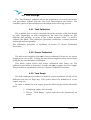
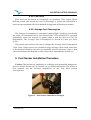
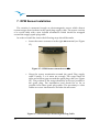
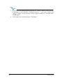
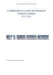
M1InstallationManual 4.5.4. Fuel Units Fuel level can be shown in Percentage or Centilitres. This option allows defining which unit should be used. If percentage is chosen the calculation is based on the maximum fuel level defined during tank calibration procedure. 4.5.5. Average Fuel Consumption The average consumption is calculated during flight, dividing periodically the value of consumed fuel by the elapsed time. This calculation is repeated indefinitely when the rotation is greater than 0 and the fuel level can be determinate. The Average Fuel Consumption is shown in Litres per Hour (L/H). This menu option allows the user to change the Average Fuel Consumption value. Since values need to be calculated using averages, these need some time to be obtained, therefore the user can manually insert a reference value so that other calculations that depend on this value can be immediately carried out. 5. Fuel Sensor Installation Procedure Caution: The fuel sensor installation is a delicate, and potentially dangerous, process, which should only be carried out by skilled technicians. The sensor is fuel certified, but the incorrect installation, or use, may have serious consequences. Figure 5 – Fuel Sensor Installation Example Version 1.0 12 5.1. Fuel Sensor Position Considering the height measured by the sensor is proportional to the length of the immersed part, the fuel sensor should be vertically installed (see Figure 6 a)). However, an inclined position is possible provided that sealing is guaranteed (see Figure 6 b)). Figure 6 – Installation position In order to grant the measure accuracy the sensor tube should not have any obstacle closer than 10 mm (see Figure a)). Special care should be taken with the distance to the tank bottom. If required the sensor length can be reduced trough the procedure defined in section 5.2 Fuel Sensor .Cutting Procedure.Otherwise, the installation continues with tank calibration according section 5.4 Tank calibration. 13 Version 1.0 M1InstallationManual 5.2. Fuel Sensor .Cutting Procedure The fuel sensor supplied with M1 has a default length. If required the sensor can be shortened. The first step for shortening the fuel sensor is to decide the correct length of the metallic tube which will be inserted in the tank. 5.2.1. Deciding Sensor Length In order to determine the sensor length it is necessary to consider the following points: • The minimum sensor length is 200 mm. • A minimum distance of 10 mm should be maintained between the sensor metallic tube and any other surface, including the tank walls. Figure 7 – Critical Sensor Measures Version 1.0 14 Taking into account the previous points the length can be easily calculated. For a vertical installation the length corresponds to the value L of Figure 8. Figure 8– Sensor length 15 Version 1.0 M1InstallationManual 5.2.2. Cutting the Metallic Tube The sensor cut should be made using an adequate tool (eg. Pipe Cutter; fine toothed hacksaw). Figure 9 – Cutting the Sensor After cutting the metallic, outer, and inner tube carefully remove the remaining jagged edges using adequate tool. Figure 10 – Sensor after being cut Version 1.0 16 The sensor has a small hole on the bottom. This hole is necessary to allow fuel entry. (see Figure 11). Figure 11 – Sensor hole If cutting the sensor leads to the elimination of the hole a new one should be made using 4 mm drill. After all the above procedures were done all the surfaces must be cleaned and specially without filings. The cutting procedure is terminated with the insertion of the special PTFE terminator supplied with the sensor (see Figure 12). The main objective of this terminator is to avoid the contact between the centre aluminium rod and the outer tube. Furthermore, the distance between the rod and the outer tube should be keep constant along all sensor length. Attention: Contact between the centre aluminium rod and the outer tube alters significantly the measures. Figure 12– End Plug placement 17 Version 1.0 M1InstallationManual After introducing the end plug, the outer tube should be slightly, and symmetrically, smashed in order to ensure that the plug will not getting out (see Figure 13) Figure 13 – Finishing the tube After cutting the sensor it is necessary to calibrate it according to the next procedure. 5.3. Sensor Calibration Procedure Sensor calibration allows the M1 to recognize the new probe length after the cutting process. The calibration process should be made after install the sensor on the tank. However, it can also be made before the installation using an adequate fuel recipient. Before start the calibration process assure that you have enough fuel to totally immerse the probe. You should also guaranty that M1 is charged. Then do the following Steps: 1- With M1 off connect the fuel sensor. The thank should be empty and the sensor not in contact with fuel. 2- Turn on the M1, enter Menu, and select the “Fuel Settings” option. Version 1.0 Fuel Settings 18 3- Choose the “Calibrate Sensor” option 4- The M1 ask you to confirm the sensor calibration process. By default the flashing option is “No”, so you should choose “Yes”. 5- The sensor ask you to confirm that sensor is dry (i.e. not in contact with the fuel). You should choose “Yes”. 6- A message “Wait…” appears on the display while the M1 acquire the empty tank state. The acquisition takes approximately 3 seconds. Calibrate Sensor Are You Sure Yes No Sensor Dry? Yes No Wait .... 7- After 3 seconds have elapsed the M1 will ask if the sensor is fully immersed. Fill the tank to full capacity making sure the sensor is fully immersed. appears asking if the sensor is immersed. 8- When the tank is completely immersed the value on the screen should be around 1000 (the value should be greater than 200). At this point you should confirm the value using S2 key. 9- A message “Wait…” appears on the display while the M1 acquire the full tank state. The acquisition takes approximately 6 seconds. 10- If the calibration was successful than the message “Sensor Calibrated” appears on the screen, otherwise an error message will be shown. Despite the message you should press a key in order to continue. 19 Sensor Immersed? Ok Value: 923 Wait .... Sensor Calibrated Version 1.0 M1InstallationManual 5.4. Tank calibration The available fuel is calculated from the measure of the fuel height on tank. Depending on tank configuration, the same fuel height can give different fuel quantities. In order the right calculation can be made a calibration procedure is necessary. This calibration procedure establishes a relation between fuel height, and fuel quantity. The calibration process is based on a simple idea. After asking for a standard measure definition, the M1 keeps asking the user to spill measures on the tank until it is full. For each added measure the corresponding height is saved. Later the fuel quantity can be calculated by interpolation. The calibration process requires one M1 and a calibrated fuel sensor correctly installed. If enough fuel is available to completely fill the tank ,follow the next steps: 1- Start with an empty tank, and the fuel sensor correctly connected to the M1. 2- Turn on M1. Enter menu mode and select “Fuel Settings”. 3- Within the Fuel Settings “Calibrate Tank” option. menu select 4- The first step is the definition of the standard measure. By default the standard measure is 100 cl. In this step user can alter the standard measure value, or skip the alteration and maintain the previews definition. 5- The standard measure value can vary between 5cl and 200cl. Value can be altered using keys S1 and S3 and confirmed using S2 Key. Version 1.0 Fuel Settings Calibrate Tank Set Measure? Skip Val=150cl Use <- and -> Value: 150cl 20 6- Depending on the first value measured by the sensor the M1 can ask the user to confirm if tank is really empty. In case “No” is selected the calibration process is aborted. Tank Empty? No Yes 7- In this step M1 waits for a fuel quantity, equal to the “standard measure” value, be added in the tank. For example, if the standard measure value is 100 cl, then 100 cl of fuel should be added in the tank. After putting the fuel on tank it is important to wait for the stabilization of the fuel before selecting “Done” option. Waiting Measure Done Cancel 8- After a measure being added the M1 asks the user if tank is full. If “No” is selected the process returns to point 7, otherwise, all values are saved in memory and calibrations ends. Tank Full? No Yes Note: Smaller “standard measure” values allow more accurate fuel level calculation, particularly in tanks with irregular shapes. However, the chosen value should cause fuel height variations greater than 1 centimetre. The maximum number of measures is 30. Once the calibration is done M1 can calculate data as: fuel level; average fuel consumption; remaining flight time. 21 Version 1.0 M1InstallationManual 6. Temperature Sensor Installation The temperature sensor supplied with M1 is a thermistor capable of measures up to 250ºC. Figure 14 – Example of Temperature Sensor Installation Local The sensor terminator is a standard M8 ring which can be installed in any motor screw. The installation in a screw instead of more common spark plug installation has several advantages, namely: • It’s easier to install since most of the times the spark plug hole is to small and inaccessible. • It’s more definitive since it is not necessary to remove the sensor when spark plug need to be changed. • It’s more robust since working temperature range is smaller. The main drawback of the sensor installation in a screw is an higher delay in the response to a motor temperature increase. Flymaster can supply different temperature sensors with different measures. Version 1.0 22 7. RPM Sensor Installation The rotation is measured trough an electromagnetic sensor which detects current surges that circulates in the spark plug supply cable. The sensor consists of a coaxial cable with a non isolated termination which should be wrapped around the supply spark plug cable. In order to install the sensor the following steps should be made: • Insert the sensor connector in the right M1 terminal (see Figure 15). Figure 15 – RPM Sensor connection to M1 • Wrap the sensor termination around the spark Plug supply cable. Usually, 3 to 4 turns are enough. The wraps must be tight and without gaps around the spark plug cable (see Figure 16) . The position of the wraps should be as close as possible to the spark plug. The installation local should be as far as possible from other spark plug cables. The proximity to other cables can cause interferences and alter the measures. Figure 16 – Sensor Wraps Around Spark Plug Cable 23 Version 1.0 M1InstallationManual The ideal number of turns is difficult to predict since it depends on several factors. A higher number of turns increase sensibility to the R.P.M., but also to noise, so more interferences can occur. A lower number decreases sensibility which can cause wrong measures especially at higher rotation values. After install the sensor, if the rotation value is not correct different number of turns and sensor position should be tried. 8. Updating firmware The update of the firmware is a simple procedure that adds new features to the M1 firmware. Before beginning update procedure make sure you download from our site (www.flymaster-avionics.com) the next list of files: • FlymasterUSBdrivers.msi (USB Drivers) • M1Firmware.m1n (Firmware M1) • FlashM1Install.msi(updating software) When you have all the files you can start the update procedure. The first step of the updating procedure consists in installing the USB drivers on the PC. In order to do that you should run the FlymasterUSBdrivers.msi file and follow the on-screen instructions. Next you need to install the update application, run the FlashM1Install.msi and follow the on-screen instructions. 1- Execute the FlashM1Install.msi application. 2- Select the M1Firmware.m1n file previously downloaded from the web site. 3- Push the “Send” button. A message “Waiting M1…” will appear on screen. 4- Hold the “Menu” (S2 key) button on your M1, and insert a paper clip into the reset orifice on just above the usb connector on the M1 in such a way as to reset the M1. Version 1.0 24 5- Release the reset button while keeping the “Menu” button. Once you see a message on the FlashM1 “Erasing memory…” you may release the “Menu” button. If the message doesn’t appear within 5-7 seconds reset the M1 again. 6- Wait until you see the message “Complete.” 25 Version 1.0