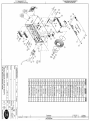
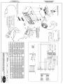
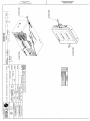
1
MTR –ST BOX Far East
User’s manual
MTR-ST Head BOX
Far East
(Single, double)
Installation and use manual
(Rev. -)
The informations in this handbook have
purpose only indicative and it is possible that
they changed without communication
obligation. However, Maser Automation does
not take any responsibility for possible
errors.
The partial or total reproduction of this
handbook it is absolutely forbidden. In order
to copy these informations it is necessary
contacting with the Company MASER
AUTOMATION S.r.l..
M04130MT.R-
MTR-ST BOX Far East
User’s manual
Document N° :
M04130MT.R-
Title :
MTR-ST Head BOX Far East ( single, double)
User Manual
Rev. :
-
M04130MT.R-
REVISION’S INDEX
Rev.
–
Description
Issue
Date
Editing
Check
Approvals
12-11-04
RS – C. Calzolari
RS – S. Gilli
M. Tedeschi
SIGNATURE
Claudio Calzolari
SIGNATURE
Samuele Gilli
SIGNATURE
Mauro Tedeschi
Pag. 2 di 28
MTR-ST BOX Far East
User’s manual
M04130MT.R-
INDEX
1
INTRODUCTION.........................................................................................................................................4
1.1
MODULARITY ..........................................................................................................................................4
1.2
REMOTE CONTROL .................................................................................................................................4
1.3
EASY SETTING ........................................................................................................................................4
1.4
AUTOCHECK ...........................................................................................................................................4
1.5
DESCRIPTION .........................................................................................................................................4
1.5.1
MTR-ST Double Configuration .....................................................................................................5
1.5.2
MTR Display Unit..........................................................................................................................5
1.5.3
MPG PULSER ..............................................................................................................................5
1.5.4
Preset Unit ....................................................................................................................................5
1.6
HEAD TURNING-ON .................................................................................................................................6
1.7
HEAD TURNING-OFF ................................................................................................................................6
1.8
TECHNICAL CHARACTERISTICS ................................................................................................................7
1.9
STATE OF THE ART..................................................................................................................................8
2
SERVICE KEYS..........................................................................................................................................9
2.1
UNIT PRICES PROGRAMMING ...................................................................................................................9
2.1.1
Pump A price programming ..........................................................................................................9
2.1.2
Pump B price programming ........................................................................................................10
2.1.3
Mixer prices programming ..........................................................................................................10
2.2
PARAMETERS PROGRAMMING................................................................................................................11
2.2.1
Metric Parameters programming ................................................................................................11
2.2.2
Not Metric Parameters programming .........................................................................................12
2.2.3
Programming parameters list......................................................................................................12
2.2.4
“General “ parameters ................................................................................................................13
2.2.5
"Pump A" parameters .................................................................................................................17
2.2.6
"Pump B" parameters .................................................................................................................19
2.3
ERRORS SIMULATION ............................................................................................................................21
3
INSTALLATION AND CONNECTIONS ...................................................................................................22
3.1
3.2
3.3
3.4
3.5
3.6
3.7
3.8
3.9
3.10
4
CONNECTION WITH DANGEROUS ZONE ...................................................................................................23
SERIAL CONNECTION ............................................................................................................................23
MINIMUM SIGNAL LEVEL ........................................................................................................................23
SUPPLY CONNECTIONS .........................................................................................................................23
MANUAL/AUTOMATIC CONTROL .............................................................................................................23
SOLENOID CONNECTION ........................................................................................................................23
LIGHTING CONNECTION .........................................................................................................................24
SINGLE, DOUBLE, SINGLESIDE, DOUBLESIDE: ..........................................................................................24
EMERGENCY BUTTON............................................................................................................................25
VAPOUR RECOVERY .........................................................................................................................25
HEAD WORKING .....................................................................................................................................25
4.1
4.2
4.3
FREE METHOD ....................................................................................................................................25
PRE-PAYMENT METHOD ....................................................................................................................25
POST-PAYMENT METHOD .................................................................................................................26
5
ERROR MESSAGES ................................................................................................................................26
6.
METER CALIBRATION ........................................................................................................................28
7.
CONNECTION DRAWINGS .................................................................................................................28
Pag. 3 di 28
MTR-ST BOX Far East
User’s manual
M04130MT.R-
1 Introduction
The MTR-ST head is a good modular product, is possibility to control it with a serial system that give
information about the dispenser and head status.
This system is create observing the maintenance/service’s needs in fact MTR-ST is easy to program (it not
necessary to use notebook PCs) and is able to autocheck troubles.
1.1
Modularity
The basic product is MTR-ST Single/Single Face Configuration, it is able to control 1 dispenser with 1
hydraulics and 1 nozzle (Single config.) with 1 display (Single Face); it is possible to have the MTR-ST
Double/Double Face, adding any modules, in this case the head control 2 dispenser, 2 hydraulic, 2 nozzle
and 2 displays (1 for each side).
1.2
Remote control
The head can be connecting with a HOST that control all the operation on the dispensers. The host control
consist in a simple recording of the events for each dispenser, or a complex control of permission’s refuels of
all dispensers; all this operations are possible because the firmware’s heads communicate with a protocol
that contains the functions needed.
For more information about the communication protocol referring to M02996MT MASER AUTOMATION
GMS Manual.
1.3
Easy setting
It is possible to customise the head during the installation by using the programmable parameters for this
reason the product is flexible and adaptable for foreign market needs.
1.4
Autocheck
The MTR-ST is able to check all events status trough a complex control that permits a fast operation’s
service, infact in case of failure the diplays shows the fault-code correspondent.
1.5
Description
Most important part of MTR-ST Head configurations:
- MTR-ST Single Unit
- MTR-ST Double Unit
- MTR Display with totalizer
- MTR Display without totalizer
- MTR Preset Unit (16 keys and 16 characters)
- MPG Pulser
- MTR Display/Preset Cable Double/Double side
- MTR Display/Preset Cable Double/Single side
M30283
M30246
M30249
M30247
M30248
M40231
M21051
M21069
Pag. 4 di 28
MTR-ST BOX Far East
User’s manual
M04130MT.R-
1.5.1 MTR-ST Double Configuration
Main unit of system:
- to the MTR-ST are connect the displays, the pulsers and the preset units
- in the terminal board there are the power output for driving the contactors
- there is output for vapour recovery system
- RS485 interface with HOST connection
- Power fail system for recording last refuel events on volatile support
- Optoinsulation for each input or output
- Possibility the driving 2 hydraulics, 2 nozzle with display for each side of the dispenser.
1.5.2 MTR Display Unit
Peripheral unit of system that show all the information necessary to the clients or service operator (in case of
setting configuration it is necessary to use a PC):
- In the display there are 3 lines : 1 line shows the total amount (with 6 digit), 2 line shows the volume
(with 6 digit), 3 line shows the unit price (with 4 digit)
- For each line it is possible to set more decimals
- MTR Display Unit is rearlighting in different colours
- MTR Display Unit can have an electromechanical totalizer (with 7 digit) that counts the total amount of
litres refuelled from the nozzle associate.
- Is connect via serial with the head and receive main supply from the head
- MTR Display Unit have a special circuit that conserve all the information of last refuels events until
20min after power fail
- MTR Display Unit Address: it is possible to set the address of the display unit setting the jumpers
presents in the connector used for the serial connection, for the reason is possible to have in the same
serial line until 4 MTR Display Unit, in according to the setting configuration jumpers on the display
cable.
- The communication troubles between MTR-ST and MTR Display Unit are displayed on the 3rd line of the
displays working.
1.5.3 MPG PULSER
Is an increasing encoder build inside an explosion-proof case, it works intercepting 2 light beams. The pulser
works follow an optical principle: a disk breaks two light beams. Each light beam drives a channel that
produces a squared wave. The waves are phase shifting of 90° for inform the head about rotation of the
pulser (clockwise or counterclockwise).
Each pulser is monitoring by MTR-ST in two ways:
-
MTR-ST verifies that the absorption of pulser is in a right range of current.
MTR-ST verifies that the gap between the pulses's number of any channel is in a right range.
Both failure condition is shows on the display at the beginning of refuel, for reset the failure message it need
to put the nozzle in the dispenser and do a new refuel operation.
1.5.4 Preset Unit
The Preset Unit is a system that contain:
- Label keyboard with 16 keys
- LCD Display with 16 characters lighting
- The contrast of the display is setting trough the keyboard directly (keys F1 and F2)
- Is connect at MTR-ST and MTR Display in serial way, the main supply is made by the same connection
- Preset Unit have address, and it is possible to connect until 2 Preset Unit at the same MTR-ST
- The setting is made by the main system unit (MTR-ST) and don’t need any program operation
- With Preset Unit it is possible to set volume refuelable and unit price, it needs to digit the value
(volume/price) and selects preset mode. The dispenser near the target reduces the fuel-flow and arrives
at the value prefixed.
Pag. 5 di 28
MTR-ST BOX Far East
User’s manual
1.6
M04130MT.R-
Head turning-on
The turning-on operation consists in supplying the head with voltage corrected in accordance with working
specification data.
At the turning-on the head can delay some seconds to begin working with reference to the initial
programmable delay, in order to let all connected devices correctly start.
Than the display cards are tested to check if the display is perfectly working and the operation finishes
displaying on each connected display card the entered unit price and the last delivery data.
1.7
Head turning-off
In case of supply voltage drop, the possible delivery in course is stopped and the relative data are stored in
an EEPROM memory at illimitated retaining.
In addition, the displays show an error message indicating the voltage drop, which is displayed with the last
delivery data for about 20 minutes on the LCD display.
However, when the head is in operation again, it shows the last effected delivery data, allowing a possible
check.
Pag. 6 di 28
MTR-ST BOX Far East
User’s manual
1.8
M04130MT.R-
Technical Characteristics
Max flow-rate
Display
Hydraulic input 1
Hydraulic output 1
Hydraulic input 2
Hydraulic side output 2
Other input
Black-out protection
Serials gate
Dimensions & weights
Temperature range
Supply conditions
250 Lit/min.
Liquid crystal display
6 digit per total amount line
6 digit per volume line
4 digit per unit price line
lighting
2 channels for each pulser
1 input control of minimum level at 12Vdc
1 input nozzle switch at 12Vdc
4 input preset keyboard
1 driver channel vapour recovery system
1 control contact engine at 28Vac 1A
1 control high-flow solenoid at 28Vac 1A
2 channels for each pulser
1 input control of minimum level at 12Vdc
1 input nozzle switch at 12Vdc
4 input preset keyboard
1 driver channel vapour recovery system
1 control contact engine at 28Vac 1A
1 control high-flow solenoid at 28Vac 1A
MAN/AUT control at 12Vdc
Program button PR
Increase button IN
Restore metric parameters switch SE
3 input for MIX configuration
Saving data
Display for 20 min from last refuel operation
Display last refuel operation at turn-on head
1 gate for serial connection at MTR Display Unit and Preset
Unit in Current Loop Mode
1 gate RS485 for serial connection at the host
MTR ST D Unit:
350 x 310 x 70 mm x 2700 gr.
MTR ST Q Unit :
330 x 425 x 70 mm x 3250 gr.
MTR display Unit: 200 x 210 x 35 mm x 660 gr.
MPG Pulser Unit:
63 x 92 x 36 mm x 350 gr.
MTR Pred. Unit:
140 x 70 x 30 mm x 150 gr.
-20° C +60° C
Voltage
:
220 Vac -20% +10%
Frequency
:
50 Hz 60 Hz
Power
:
< 40 W in max config.
Pag. 7 di 28
MTR-ST BOX Far East
User’s manual
1.9
M04130MT.R-
State of the art
!
N.B. State of the art of the equipment stands for minimum configuration of the system
for which this manual is valid, concerning both electronic cards revision and
installed programs revisions.
The state of the art of the equipment, for which this programming manual is valid, must be like or more
advanced than what follows:
MTR-CPU card
M20179 REV. H: MTR-CPU board double configuration
Gal MTE rev. 3.1
EPROM MTR-CPU rev. 7.60 Far East
INT-MTR card
M20518 REV. - : INT-MTR rev. - card
MTR-LCD/R card
M21031 REV. - : MTR-LCD 6 digit R
Microcontroller 68HC705C8 MTR LCD rev. 1.28 Far East
Pag. 8 di 28
MTR-ST BOX Far East
User’s manual
M04130MT.R-
2 Service keys
The head unit is provided of two keys and a switch for each MTR-CPU board, necessary to the unitary prices
modification and the parameters personalization programming and it has also an error simulation switch. The
list and the relative function are the following:
- Programming key, “ Pr” necessary to enter in programming mode to modify the price and the customise the
head parameters. In this function it is possible to move on single parameter or digit.
- Increasing key, “In” necessary to increase the single digit (parameter or price)
- Simulation error key, “Se” this switch must be closed before modify some metric parameter or displaying
errors messages (Italian Metric Office’s request)
2.1
Unit prices programming
With a simple operation it is possible modify the pump A price and eventually also the pump B price in the
case of a double head.
In the case that the head is configured as mixer it is possible to modify the prices relative to the different
mixer percentages up to a maximum of 8 different prices.
The necessary and essential condition in order to do the modification it is that the head is in repose situation
and that any delivery is in course, so the nozzle/s must be put in their place.
To enter the unit price modification phase it is necessary to use the programming key, pressing it once so
that it displays the price relative to the pump A.
2.1.1 Pump A price programming
The complete operations sequence necessary in order to modify the pump A unit price is the following:
•
•
•
•
1 - check that the head is on
2 - check that the nozzle/s are connected in their own place
3 - press the Pr programming key only one once
4 - the display card/s show the following information:
P-P
XXXX
•
9
shows the parameter relative to the pump A price
shows the pump A price
5 - through the programming keys use enter the new price beginning from the 1^ figure on the left in the
following way:
- with the increasing key In enter the correct value
- with the programming key shift Pr pass to the following figure until the last figure introduction.
•
•
6 - the new price entering is over and to escape from this phase it is necessary to wait some seconds
then the head starts its normal working by itself.
7 - escaping from the programming phase, the head effects a display test displaying at first all 8s then all
blanks and at the end it writes the new entered price resetting volume and amount as display.
Pag. 9 di 28
MTR-ST BOX Far East
User’s manual
M04130MT.R-
2.1.2 Pump B price programming
If the head is double, when the price entering relative to the pump A is finished (point 6 completed point in
the operation sequence described in the previous paragraph), it is necessary to modify the pump B price.
•
1- the display card/s show the following information:
P-P
10
XXXX
•
•
•
shows the parameter relative to the pump B price
shows the pump B price
2 - through the programming keys use, enter the new price beginning from the 1^ figure on the left as for
the pump A price.
3 - when the price introduction relative to the pump B is finished in order to escape from this phase it is
necessary to wait some seconds.
4 - escaping from the programming phase, the head effects a display test displaying at first all 8s and
then all blanks, at the end it writes the new entered price resetting volume and amount as display.
2.1.3 Mixer prices programming
If the head is configured as mixer it is possible to program 8 different prices corresponding to 8 different
mixture degrees that the head can manage.
The necessary operations in order to enter in programming are the same described in the par. 2.2.1. relative
to the pump A; the only difference is that you have a 8 consecutive prices sequence as follows:
P-P 1
P-P 2
P-P 3
P-P 4
P-P 5
P-P 6
P-P 7
P-P 8
:
:
:
:
:
:
:
:
mixture price # 1
mixture price # 2
mixture price # 3
mixture price # 4
mixture price # 5
mixture price # 6
mixture price # 7
mixture price # 8
At the end of the last price introduction, in order to escape from this phase, it is necessary to wait only some
seconds. Escaping from the programming phase, the head makes a display test displaying at first all 8s then
all blank and at the end it writes the new price relative to the entered mixture, degree resetting volume and
amount as display.
Pag. 10 di 28
MTR-ST BOX Far East
User’s manual
2.2
M04130MT.R-
Parameters programming
In order to allow a head personalization, it is possible to modify a parameters series, some regarding, the
specific head configuration, others the pump A functionality and others again the pump B functionality.
The three parameter types are identificated as follows:
"general" parameters
P-0
X
general parameters identification
"pump A " parameters
P-1
X
pump A parameters identification
"pump B " parameters
P-2
X
pump B parameters identification
A detailed different programmable parameters description happens in the next paragraphs.
An head parameters programming feature is that they are shared in two groups about the “Metric”
importance of each single parameter; so we have some parameters groups as follows:
“Metric” parameters
“Not Metric” parameters
The difference between those two groups is in the programming accessibility, in fact the first group
concerning the “Metric” parameters is subordinate to the metric tie, so to modify the parameters is
necessary to remove the metric tie put to protect the simulation switch and then operate on it besides the
programming switch.
2.2.1 Metric Parameters programming
To enter the “Metric” parameters programming phase it is necessary to operate as follows:
•
•
•
•
•
•
•
•
1 - switch off the head
2 - remove the protection metric and switch-on error simulation switch
3 - wait about ten seconds before switching on the head
4 - switch on the head again
5 - each display shows the relative address and the program release then the message SP (Start
Programming) that is displayed
6 - turn on the SE error simulation key
7 - press the Pr programming key until the display shows that message
8- after some seconds the head makes a display clear then it displays the first programmable parameter
as follows:
P- 0 3
X
•
•
this is the "general" type parameter
this is the parameter value
9 - effected the parameter modification go on modifying parameter by parameter.
10 - to escape from the parameter programming phase it is necessary to have a quick look at all
parameters until the message EP (End Programming) is displayed after that the head effects a displays
check and displays the unit price and the last effected delivery.
!
N.B. During this programming phase is possible to modify all programming
head parameters.
Pag. 11 di 28
MTR-ST BOX Far East
User’s manual
M04130MT.R-
2.2.2 Not Metric Parameters programming
To enter the “ Not Metric” parameters programming phase it is necessary to operate as follows:
•
•
•
•
•
•
1 - switch off the head
2 - wait about ten seconds before switching on the head
3 - switch on the head again
4 - each display shows the relative address and the program release then the message SP (Start
Programming) is displayed
5 - press the Pr programming key until the display shows that message
6 - after some seconds the head makes a display clear then it displays the first programmable parameter
as follows:
P- 0 1
X
•
•
this is the "general" type parameter nr. 1
this is the parameter value
7 - effected the parameter modification go on next modifying parameter by parameter (is possible to
modify only those “Not Metric”).
8 - to escape from the parameter programming phase it is necessary to have a quick look at all
parameters until the message EP (End Programming) is displayed after that the head effects a display
check and displays the unit price and the last effected delivery.
N.B. During this programming phase is possible to modify only the ”Not
!
metric” type programming head parameters. However those of “Metric”
type are displayed but it is not possible to modify them.
2.2.3 Programming parameters list
N° PAR.
P–01
P–02
P–08
P–09
P – 0 10
P – 0 11
P – 0 15
P – 0 16
P – 0 17
P – 0 18
P – 0 19
P – 1 10
P – 1 11
P – 2 10
P – 2 11
Description
Head Configuration
Head address
Preset key n° 1 value (not used)
Preset key n° 2 value (not used)
Preset key n° 3 value (not used)
Numerical Rounding amount/litres
Numerical Rounding Value
Amounting masking
Decimals number on amount line
Decimals number on volume line
Decimals number on unit price line
Calibration coefficient
Product/Nozzle part number
Calibration coefficient
Product/Nozzle part number
Parameter kind
NOT METRIC
NOT METRIC
NOT METRIC
NOT METRIC
NOT METRIC
METRIC
METRIC
METRIC
METRIC
METRIC
METRIC
METRIC
NOT METRIC
METRIC
NOT METRIC
Pump
GENERAL
GENERAL
GENERAL
GENERAL
GENERAL
GENERAL
GENERAL
GENERAL
GENERAL
GENERAL
GENERAL
A
A
B
B
Pag. 12 di 28
MTR-ST BOX Far East
User’s manual
M04130MT.R-
2.2.4 “General “ parameters
- Head configuration -
P- 0 1
first "general" parameter identification
Xthis is the parameter value
The head can have four different configurations according to the type of connection and the first
programmable parameter allows the identification of the type of configuration that the head must assume.
- configurations single single-sided head
single double-sided head
double single-sided head
double double-sided head
- parameter value 1
2
3
4
- Head address -
P- 0 2
XX
second "general" parameter identification
this is the parameter value
The second"general" parameter is relative to the address to give to the head when this is connected to an
intelligent unit system as for example, a PC.
The address can change from 1 to 99 and, as default value, always correspond to 1.
- Use as mixer -
P- 0 3
third "general" parameter identification
X
this is the parameter value
The third "general" parameter is relative to the presence of the mixer, that is, to the distributor use as mixer.
- configuration - parameter value normal functioning
0
functioning as mixer with
1
the pulser after the mixing point
functioning as mixer with
2
the pulser before the mixing point
(control of the compensated delivery)
The default value 0 and the parameter is not displayed.
- Turning on delay -
P- 0 4
XXX
fourth "general" parameter identification
this is the parameter value
The fourth "general" parameter is relative to the delay in the head turning-on and consists of a variable
number of waiting seconds, before that the head is operative since it is on.
The delay that can be introduced varies from 5 to 999 seconds.
The default value 5 and the parameter is not displayed.
Pag. 13 di 28
MTR-ST BOX Far East
User’s manual
M04130MT.R-
- Volume unit selection -
P- 0 5
X
fifth "general" parameter identification
this is the parameter value
The fifth "general"parameter is relative to the volume unit selection that can be in gallons or in liters.
- configuration-
-parameter value-
volume unit in gallons
0
volume units in litres
1
The default value 1 and the parameter is not displayed.
- Pulses number per volume unit -
P- 0 6
XXX
sixth "general"identification
this is the parameter value
The sixth "general" parameter is relative to the pulses number per volume unit and it is a number varying
from 1 to 999. As default value, the head is programmed with 100 pulses per volume unit and actually it is a
not modifiable value.
The default value 100 and the parameter is not displayed.
- “Blank” on the initial displaying -
P- 0 7
XX
seventh "general" parameter identification
this is the parameter value
The seventh "general" parameter is relative to the hundredth number of volume unit to screen as display at a
delivery beginning and is a value varying from 0 to 99.
The default value 10 and the parameter is not displayed.
- Predetermination key 1 value -
P- 0 8
XXXXX
eighth "general" parameter identification
this is the parameter value
The eighth "general" parameter is relative to the value programming regarding the nr. 1 preselection key. As
default value, the nr. 1 key is programmed at 5 (not used)
- Predeterminator key 2 value -
P- 0 9
XXXXX
ninth "general" parameter value identification
this is the parameter value
The ninth "general" parameter is relative to the value programming regarding the nr.2 preselection key. As
default value the nr. 2 key is programmed at 10 (not used)
Pag. 14 di 28
MTR-ST BOX Far East
User’s manual
M04130MT.R-
- Predeterminator key 3 value -
P- 0 10
XXXXX
tenth "general" parameter identification
this is the parameter value
The tenth "general" parameter is relative to the value programming regarding the nr.3 preselection key. As
default value, the nr.3 key is programmed at 25 (not used)
- Numerical Rounding -
P- 0 11
X
eleventh "general" parameter identification
this is the parameter value
The eleventh "general" parameter is relative to the rounding off of xxx +/- 2 cent.
- configurationno rounding off
rounding off of +/- x centilitres
rounding off of +/- x amounts
both
- parameter value 0
1
2
3
Numerical Rounding Value -
-
P- 0 15
X
fifteenth "general" parameter identification
this is the parameter value
The fifteenth "general" parameter is relative to the kind of predetermination associated to the respective keys
- configurationrounding x centilitres/amount
rounding x centilitres/amount
rounding x centilitres/amount
- parameter value 1
2
3
- Amount masking -
P- 0 16
X
sixteenth "general" parameter identification
this is the parameter value
The sixteenth "general" parameter is relative to the masking and rounding off of one or two significant digits,
to allow the manage of one or more decimal price, but with full amount.
- configurationno masking digit
last digit masking and
rounding on last but one
last two digits masking and
rounding on last but two
The default value 0
- parameter value 0
1
2
Pag. 15 di 28
MTR-ST BOX Far East
User’s manual
M04130MT.R-
Decimal number on amount line –
-
P- 0 17
X
seventeenth "general" parameter identification
this is the parameter value
The seventeenth "general" parameter is relative to the decimals number present on the amount row (comma
position).
- configuration- parameter value no decimal (decimal point out)
0
one decimal
1
two decimals
2
The default value 0
-
P- 0 18
X
Decimal number on litres line –
eighteenth "general" parameter identification
this is the parameter value
The eighteenth "general" parameter is relative to the decimals number present on the litres row (comma
position).
- configuration- parameter value no decimals (decimal point out)
0
two masking digit
1
The default value 1
-
P- 0 19
X
Decimal number on unit price line –
nineteenth "general" parameter identification
this is the parameter value
The nineteenth "general" parameter is relative to the decimals number present on the price row (comma
position).
- configuration-
- parameter value -
no decimal (decimal point out)
one decimal
two decimals
three decimals
The default value 0
0
1
2
3
Preset selection Litres (not displayed) –
-
P- 0 20
X
fifteenth "general" parameter identification
this is the parameter value
The fifteenth "general" parameter is relative to the kind of predetermination associated to the respective keys
- configurationpredetermination in euro
predetermination in litres
- parameter value 0
1
Pag. 16 di 28
MTR-ST BOX Far East
User’s manual
M04130MT.R-
2.2.5 "Pump A" parameters
- Antiflow test enabled or not -
P- 1 2
X
"pump A" second parameter identification
this is the parameter value
"Pump A" second parameter is relative to the antiflow-table device test if it is connected or not connected.
- configuration - parameter value not connected antiflow-table test
0
connected antiflow-table test
1
The default value 0 and the parameter is not displayed.
- Volume threshold for antiflow test -
P- 1 3
XXX
"pump A" third parameter identification
this is the parameter value
"Pump A" third parameter is relative to the volume unit hundredths number after that the antiflow-table test
starts. The value that can be introduced goes from 1 to 999 and is considered only if the antiflow-table test is
connected.
The default value 30 and the parameter is not displayed.
- Antiflow test verify time -
P- 1 4
X
"pump A" fourth parameter identification
this is the parameter value
"Pump A" fourth parameter is relative to the seconds number within which the antiflow-table test is made.
The value that can be introduced as second number goes from 1 to 9 and is considered only if the antiflowtable test it is connected.
The default value 1and the parameter is not displayed.
- Maximum time without pulses for slow-down valve closing -
P- 1 5
XX
"pump A" fifth parameter identification
this is the parameter value
"Pump A" fifth parameter is relative to the maximum time without pulses after that the slow-down valve is
momentarily stopped. The maximum time is a value expressed in seconds that goes from 1 to 99.
The default value 10 and parameter is not displayed.
- Maximum time without pulses for delivery closing -
P- 1 6
XX
"pump A" sixth parameter identification
this is the parameter value
"Pump A" sixth parameter is relative to the maximum time without pulses after that the engine is not
connected and the delivery is closed. The maximum time is a value expressed in seconds that goes from 1
to 99.
The default value 60 and parameter is not displayed.
Pag. 17 di 28
MTR-ST BOX Far East
User’s manual
M04130MT.R-
- Maximum delivery time -
P- 1 7
XX
"pump A" seventh parameter identification
this is the parameter value
"Pump A" seventh parameter is relative to the maximum delivery time and is a value expressed in minutes
0’ and from 3’ to 22’.
The default value 0 and the parameter is not displayed.
- Advanced stop -
P- 1 8
X
"pump A" eighth parameter identification
this is the parameter value
"Pump A" eighth parameter is relative to the engine advanced stop expressed in volume unit hundredths is a
value that goes from 0 to 9.
The default value 0 and the parameter is not displayed.
- Volume hundredths number for slowing down beginning -
P- 1 9
XX
"pump A" ninth parameter identification
this is the parameter value
"Pump A" ninth parameter is relative to the number of centilitres before which the delivery starts the slowdown phase according to the preset value (slow-down centilitres number). This programmable value goes
from 00 to 99 (default value = 50 CL.).
P- 1 10
X
"pump A" tenth parameter identification
this is the parameter value
“Pump A” tenth parameter is the electronic calibration coefficient of the meter (see regarding chapter 6 ) The
value goes 09800 to 10200.
P- 1 11
X
"pump A" twelfth parameter identification
this is the parameter value
"Pump A" twelfth parameter is the part number for product supply from the nozzle.
Part numbers:
1 – SUPER
3 – UNLEADED
4 - DIESEL
Pag. 18 di 28
MTR-ST BOX Far East
User’s manual
M04130MT.R-
2.2.6 "Pump B" parameters
- Antiflow test enabled or not -
P- 2 2
X
"pump B" second parameter identification
this is the parameter value
"Pump B" second parameter is relative to the antiflow-table device test if it is connected or not connected.
- configuration - parameter value not connected antiflow-table test
0
connected antiflow-table test
1
The default value 0 and the parameter is not displayed.
- Volume threshold for antiflow test -
P- 2 3
XXX
"pump B" third parameter identification
this is the parameter value
"Pump B" third parameter is relative to the volume unit hundredths number after that the antiflow-table test
device. The value that can be introduced goes from 1 to 999 and is considered only if the antiflow-table test
is connected.
The default value 30 and the parameter is not displayed.
- Antiflow test verify time -
P- 2 4
X
"pump B" fourth parameter identification
this is the parameter value
"Pump B" fourth parameter is relative to the seconds number within which the antiflow-table test is made.
The value that can be introduced as second number goes from 1 to 9 and is considered only if the antiflowtable test it is connected.
The default value 1and the parameter is not displayed.
- Maximum time without pulses for slow-down valve closing -
P- 2 5
XX
"pump B" fifth parameter identification
this is the parameter value
"Pump B" fifth parameter is relative to the maximum time without pulses after that the slow-down valve is
momentarily stopped. The maximum time is a value expressed in seconds that goes from 1 to 99.
The default value 10 and the parameter is not displayed.
- Maximum time without pulses for delivery closing -
P- 2 6
XX
"pump B" sixth parameter identification
this is the parameter value
"Pump B" sixth parameter is relative to the maximum time without pulses after that the engine is not
connected and the delivery is closed. The maximum time is a value expressed in seconds that goes from 1
to 99.
The default value 60 and the parameter is not displayed.
Pag. 19 di 28
MTR-ST BOX Far East
User’s manual
M04130MT.R-
- Maximum delivery time -
P- 2 7
XX
"pump B" seventh parameter identification
this is the parameter value
"Pump B" seventh parameter is relative to the maximum delivery time and is a value expressed in minutes 0’
and from 3’ to 22’.
The default value 0 and the parameter is not displayed.
- Advanced stop -
P- 2 8
X
"pump B" eighth parameter identification
this is the parameter value
"Pump B" eighth parameter it is relative to the engine advanced stopped expressed in volume unit
hundredths and is a value from 0 to 9.
The default value 0 and the parameter is not displayed.
- Volume hundredths number for slowing down beginning -
P- 2 9
XX
"pump B" ninth parameter identification
this is the parameter value
"Pump B" ninth parameter is relative to the number of centilitres before which the delivery starts the slowdown phase according to the preset value (slow-down centilitres number). This programmable value goes
from 00 to 99 (default value = 50 CL.).
P- 2 10
X
"pump A" tenth parameter identification
this is the parameter value
“Pump A” tenth parameter is the electronic calibration coefficient of the meter (see regarding chapter 6 ) The
value goes 09800 to 10200.
P- 2 11
X
"pump A" twelfth parameter identification
this is the parameter value
"Pump A" twelfth parameter is the part number for product supply from the nozzle.
Part numbers:
1 – SUPER
3 – UNLEADED
4 - DIESEL
Pag. 20 di 28
MTR-ST BOX Far East
User’s manual
2.3
M04130MT.R-
Errors simulation
The head unit is provided of an error simulation key (called Se) useful, as the name says, to simulate the
errors that the head can find and it is used as check by the metrical inspectors.
This key, as mentioned in the head homologation certificate, must be sealed up by the Weights and
Measures office, and after each use, the head recertification must be asked.
The necessary operations to simulate errors are the following:
• 1 - Press once the Se simulation key putting it on ON position, and the displays show the first error Er 03
• 2 - In order to simulate the errors press the increasing key In and every time that the key is pressed it is
possible to see in sequential way the error displaying.
• 3 - In order to escape from this stage press once the simulation key putting it on OFF position and the head
tests the displays and will show the normal displaying.
The four errors that it is possible to simulate are the fundamental errors that the head must check in each
condition and in order they refer to:
ER03 ⇒ power supply error on the encoder
ER04 ⇒ incongruency error on the encoder
ER05 ⇒ transmission error with a display
ER08 ⇒ communication error with host
Pag. 21 di 28
MTR-ST BOX Far East
User’s manual
M04130MT.R-
3 Installation and connections
The MTR-ST Double/doubleside Unit connection is easy it is necessary to follow the main activity described
:
Mechanical fitting :
•
•
•
•
•
fit the MTR-ST Unit inside the dispenser
fit the MTR Displays inside the dispenser
connect the pulser on the meter in the lower part of the dispenser
fit the Preset Units on the dispenser
fit PR and IN keys at the head case
MTR-ST Double Unit Connections:
•
•
•
•
•
•
•
•
•
•
•
connect the MTR Display Units to the display cable M21051 at CN2, CN3, CN5, CN6 connectors
branded rispectly M1, S2, S1, M2.
connect the Preset Unit to the display cable M21051 at CN1, CN7 connectors
connect the CN4 “VR” display cable M21051 at “Display” connector of MTR-ST Unit .
connect the pulsers cables.
connect the nozzle switch cables and emergency switch cables (if requests)
connect the solenoid cables.
connect the coil's cables from conctators or relays.
connect the control level switch’s cables.
connect the MAN/AUT switch cables.
connect RS485 serial line
connect the vapour recovery cables.
SUPPLY Connections:
•
connect the MTR-ST Unit to 220Vac supply with suitable wiring cable.
LIGHTING:
•
•
connect the MTR-ST Unit to 220Vac with suitable wiring cable for lighting
connect the reactors to the lamps
For details of the connections described above referring to the following documents:
1) M21051TO MTR_ST D/Ds Far East Display Cable
2) M21069TO
MTR_ST D/Ss Far East Display Cable
3) M30176DI MTR-ST single unit VR and PC assembly drawing
4) M30174DI MTR-ST double unit VR and PC assembly drawing
5) M02962SB Connection drawing of the MTR head in standard enclosure
N.B. In order to keep out working problems, before to do possible connections
!
to other different pulser models from the MASER AUTOMATION MPG
pulser, is necessary to ask Maser Automation the approval for that
particular connection.
Pag. 22 di 28
MTR-ST BOX Far East
User’s manual
3.1
M04130MT.R-
Connection with dangerous zone
On define dangerous zone the place where is fitted the hydraulics system inside the dispenser, to garantie
the maximum insulation between hydraulics zone (dangerous) and electronic zone (not dangerous) it MUST
use cable glade for all connection.
3.2
Serial connection
The HOST connection is made in according with RS485 standard, in this way it is possible to realise long
connection (until 1200mt).On the same line is possible to connect several MTR-ST Units and others
equipments that have to wiring with the RS485 standard.
To follow RS485 standard connection it must to observe follow rules:
1) the cable must to be shielded, flame-proof , with 3 wires ( data, data*, GND)
2) each cable must to be connected to the earth trough the shield
3) in case of multiconnection it must to do parallel connection between the wires
4) at the extremity of the cable it must to be fixed a resistor 180 Ohm between data and data*
For connect MTR-ST Unit to a PC it must to use a special equipment MSA interface (RS232-RS485)
installed before the PC.
3.3
Minimum signal level
In general inside the tanks are installed the Minimum Levels switch that troght MTR-ST give information
about the level of fuel inside the tank.
3.4
Supply connections
To reduce the noises produced by engine’s supply it must to connect separately the supplies lines of each
electronic equipment, in this case engines, MTR-ST Unit, Lighting have different supply lines.
3.5
Manual/Automatic control
Normally MTR-ST is supplied in Manual mode function; this setting is made by a jumper fit on Head terminal
board inside the dispenser (see M30246DI page 2). In case of system installation (some dispensers under
HOST control), it need to install the Manual/Automatic control in a safety zone.
3.6
Solenoid connection
The solenoid has two commands to control the fuel-flow in case of refuelling, in general are used both in
following ways:
1) low fuel-flow valve control (open/closed)
2) high fuel-flow valve control (open/closed)
is very important to connect both controls in the right way to avoid any wrong function of the dispenser.
In case of 24Vac supply is possible to connect the solenoid to the MTR-ST terminal board.
Pag. 23 di 28
MTR-ST BOX Far East
User’s manual
3.7
M04130MT.R-
Lighting connection
On the MTR-ST Unit is possible to fit two reactors for lamps low energy, for each reactor is possible to
connect until two bloom lamps 9W in serial configuration.
3.8
Single, double, singleside, doubleside:
MTR-ST Unit configurations:
SINGLE : the dispenser has 1 hydraulic/1 nozzle and pulser, solenoid, contactor, nozzle switch/emergency
sw. referring rispectly to terminals : “PULSER1”, “EV1”, RELE1, NOZZLE SW.1 (see M30246DI page 2). (*)
DOUBLE : the dispenser has 2 hydraulic/2 nozzle and pulser, solenoid, contactor, nozzle switch/emergency
sw. referring rispectly
for hydraulic1 to terminals : “PULSER1”, “EV1”, RELE1, NOZZLE SW.1
for hydraulic2 to terminals : “PULSER2”, “EV2”, RELE2, NOZZLE SW.2 (see M30246DI page 2). (*)
SINGLE SIDE : (it must to use M21069 Display cable) in case of single dispenser connect MTR Display to
CN2 (“M1”) connector of MTR display cable and Preset Unit to CN1 connector of MTR display cable.
In case of double dispenser connect
1st MTR Display to CN2 (“M1”) connector of MTR display cable and Preset Unit to CN1 connector of MTR
display cable and
2nd MTR Display to CN6 (“M2”) connector of MTR display cable and Preset Unit to CN7 connector of MTR
display cable.
DOUBLE SIDE : (it must to use M21032 Display cable) in case of single dispenser connect 2 MTR Display
to CN2 (“M1”) and CN5 (“S1”) connector of MTR display cable and Preset Unit to CN1 connector of MTR
display cable.
In case of double dispenser connect
1st MTR Display to CN2 (“M1”) and CN5 (“S1”) connector of MTR display cable and Preset Unit to CN1
connector of MTR display cable and
2nd MTR Display to CN6 (“M2”) and CN3 (“S2”) connector of MTR display cable and Preset Unit to CN7
connector of MTR display cable.
(*) : it must to know the kind of hydraulics installed inside the dispenser.
Pag. 24 di 28
MTR-ST BOX Far East
User’s manual
3.9
M04130MT.R-
Emergency button
The emergency button (if request) must be installed between the nozzle switch and MTR-ST Unit, it works
simulating the “insert nozzle” turning-off the dispenser (hydraulic, engines, pulser, and solenoid).
3.10 Vapour Recovery
In case of MTR-ST Unit fit inside a dispenser with Vapour Recovery circuit is possible to connect it to the
MTR-ST electronic module. At the moment is not possible the connection to the DIN terminal board.
4 Head working
The head can have three different kinds of working at user discretion:
FREE method with free delivery or through predetermination
PRE-PAYMENT method
POST-PAYMENT method
The different functionality and the particularity of each working method are described in the next paragraphs.
4.1
FREE method
This is the petrol service traditional working system, where at the nozzle extraction, the delivery starts, the
delivered volume counting and displaying are effected and only at the nozzle reinsertion, the delivery in
course finishes. This working is possible only with the head set with MANUAL mode.
FREE delivery can happen also through predetermination and, in this case, it is possible to set the petrol
quantity, or amount, that it is necessary to deliver. So, the delivery starts normally and finishes automatically
when it reaches the value defined at the delivery beginning.
Some working particularities in case of a predetermination are the followings:
•
•
•
•
•
•
4.2
the predetermination and the relative amount display that it is necessary to deliver is possible only when
the nozzle is inserted.
during the delivery, it is possible to cancel the possible predetermination effected, through the key
CLEAR and so the delivery becomes free.
in the same way during the delivery it is possible, in case there is not the predetermination, press one of
the working keys and the delivery will finish at the last value relative the selectioned key.
the slowing down effected at the end of the delivery is not fixed by a constant value, but it is a value
function of the quantity petrol that is delivered in the time unit.
when the next delivered value to the predetermined value is reached, an amount masking delivered is
made, displaying on the display the prefixed value selectioned in the predetermination phase.
in case of inactivity engine at the end of the delivery it is possible to work on the head, modifying the
delivery advanced stopping parameter, in order to have a delivery correctly closed corresponding to the
predetermination.
PRE-PAYMENT method
In this case the head has to be intelligently connected with a self-service system, from which it receives the
messages relative to the operations to effect. In fact in the working as pre-payment the head wait for a
message from the HOST to deliver an exact amount. When the delivery is finished the head, also taking out
the nozzle, does not effect operations and waits for other messages from the system to which is connected.
This kind of working is possible only with the head set in AUTOMATIC mode.
During the working as Pre-payment the preset unit are not operative and it is not possible, for obvious safety
reasons, to modify the delivery amount transmitted from the pre-payment system to the head.
Pag. 25 di 28
MTR-ST BOX Far East
User’s manual
4.3
M04130MT.R-
POST-PAYMENT method
Also in this case the head must be connected ON-LINE with an HOST of system, during the working as postpayment the head always waits for the consens from the HOST unit in order to deliver, at the end relative
data are transmitted to the HOST for the counting.
This kind of working is possible only with the head set in AUTOMATIC mode.
During the working as Post-payment the preset unit are active and obviously it is possible to select the
amount that it is necessary to deliver.
5 Error messages
The head is provided with a self check system, that let always find, possible working anomalies, displaying
on the display cards the kind of error happens.
The display messages relative to the errors that can happen are the following:
•
Er00:
indicates a power supply failure.
•
Er03
indicates a power supply problem on the encoder.
•
Er04
indicates an incongruency on the encoder channels.
•
Er05
indicates a communication error with a display card or error preset unit.
•
Er06
indicates a problem of minimum level in the tank.
•
Er07
indicates a petrol loss error (flameproof).
•
Er08
indicates a communication error with host.
•
Er09
indicates an error in the stored parameters in EEPROM.
•
Er088
is displayed when a totals counter is in overflow and over the maximum value.
When an error message is displayed, check, as following explained, which kind of anomaly it is then, if the
failure persists also trying to insert and take out the nozzle, consult the technical assistance.
•
Er00:
happens when the head is turned-off or when there is not power supply to the head. If such
message appears only on a display and not on all those connected to the head, therefore the power
supply failure is limited only to that display so the problem could be due to the card connected from the
display cable or to a prolem on the card.
•
Er03
happens when a power supply problem is found on the encoder. In particular if it has been
found an irregular current absorption from the pulser the display shows this error message. If the error
continues it is necessary to ask explanations to the technical assistance.
•
Er04
happens when it is found a counting difference among the two encoder channels. The
problem can be caused from one of two channels of the encoder that does not transmit pulses to the
head or can be due to a channel that it is not well connected to the terminal-board. Ask the technical
assistance.
•
Er05
happens when there is a communication error with one or more display cards or errors
preset unit.
Pag. 26 di 28
MTR-ST BOX Far East
User’s manual
M04130MT.R-
Following is explaned the errors 05 list possible and meaning :
Message
E51
E52
E53
E54
E58
E59
meaning
Communication problems with master 1 display
Communication problems with slave 2 display
Communication problems with master 2 display
Communication problems with slave 1 display
Com. problems Preset unit on side 1
Com. problems Preset unit on side 2
Connector
M1
S2
M2
S1
CN1
CN7
Work lock
Work-lock
Work-lock
Work-lock
Work-lock
No work lock
No work lock
In case of communications problems with the display the head show the error message on the display and
lock the dispenser’s work, in this case it need to reset the dispenser .
In case of communications problems on the preset units, the errors messages are shown only on the
display, if the problems is present when the head is in turn-on condition the error message is shows on the
display and it disappears at first nozzle extraction. If the problem is present in start-up conditions the
refuelling is locked and it is necessary to reset the head unit. In the table above is specified the respectly
connectors of the display units and preset units.
•
Er06
•
Er07
happens when there is the control on the petrol accidental losses, called “antiexpandment
control". Such error is always found at the delivery beginning because the check is made in the first
delivery centilitres and in a short timebreak. Both the centilitres number on which check is effected and
the duration seconds of such check are programmable as initial parameters relative to the pump.
•
Er08
happens when there is a communication error with an intelligent system to which the head is
connected. In that case, check that the connection cable is connected to both parts, otherwise ask the
technical assistance.
•
Er09
happens when the CPU finds an error in the parameters stored in EEPROM. Such message
can be displayed after the program replacement with a new release on the central card. In that case it is
necessary reinsert the initial programming parameters in order to cancel the error and reset the head
normal working.
happens when it is found a minimum level indication in the tank.
• Er088
happens during the delivery when the totals counters is overflow, is also possible to display
the totals as below:
on Display
9135
9135
9135
9135
Preset keys
tank
amount
tank
amount
Meaning
Total Litres Side A
Total Amount Side A
Total Litres Side B
Total Amount Side B
Pag. 27 di 28
MTR-ST BOX Far East
User’s manual
6.
M04130MT.R-
Meter Calibration
The electronic head MTR/ST has properly programming parameters (1 for side), of metric type protected by
a metric contraint; trough this parameters it is possible via software to correct the error of the meter. This
because, as every mechanical tools, the meter needs a calibration to be in range of measure.
Parameters:
• P – 1 10
• P – 2 10
side A
side B
The correction parameters is also named “Calibration Coefficient”. All the values delivered (number of pulses
from pulser) are correct in base of the Calibration coefficient and are visualised on the display of the head.
Calibration coefficient value:
¾
0,9800 – 1,0200
this value has 4 decimal, it hasn’t a comma and the value go from 09800 to 10200.
Procedure of calibration (for each side):
1.
2.
3.
4.
Select the Calibration coefficient at 1,0000 and delivery a quantity of fuel >/= 10 litres (VVis);
Measure the real quantity of fuel delivery with measure test (VErog);
The Calibration coefficient is (VErog/VVis) in centilitres for each pulse;
Insert the parameter, for the side A the parameter is P 1 10, for the side B the parameter is P 2 10.
7.
Connection drawings
CODE
DESCRIPTION
REL.
M02962SB Connection drawing of the MTR head in standard enclosure
A
M03250SB Connection drawing of the MTR head in standard enclosure with Eltomatic encoder
-
M03268SB Connection drawing of the MTR-ST head with mixer
A
M03266ST Drawing of the connection of the vapour recovery board to the double MTR-ST
-
M03267ST MTR-ST head MAN/AUT connectin drawing
A
M03245ST Diagram of connection between MTR-ST heads and PC by MSA interface (232-485)
-
M30176DI
MTR-ST single unit VR and PC assembly drawing
F
M30174DI
MTR-ST double unit VR and PC assembly drawing
F
M30281DI
MTR-ST Mixer assembly drawing
-
M03330NT MTR-ST – Legalization plan
A
M30294DI
MTR-LCD Display for Far East Basic assembly drawing (without totalizer)
-
M30295DI
MTR-LCD Display for Far East Basic assembly drawing (with totalizer)
-
M21051TO MTR D/B Far East Display cable
B
M21069TO MTR D/M Far East Display cable
A
M21107TO MTR S/B Far East Display cable
B
Pag. 28 di 28