1
MASTER THESIS
TITLE: Vuforia v1.5 SDK: Analysis and evaluation of capabilities
MASTER DEGREE: Master in Science in Telecommunication Engineering
& Management
AUTHORS: Alexandro Simonetti Ibañez
Josep Paredes Figueras
DIRECTOR: Roc Meseguer Pallarès
DATE: March 19 th 2013
Overview
This thesis goes into the augmented reality world and, being more specific in
Vuforia uses, searching as an achievement the analysis of its characteristics.
The first objective of this thesis is make a short explanation of what is
understood by augmented reality and the actual different varieties of AR
applications, and then the SDK’s features and its architecture and elements. In
other hand, to understand the basis of the detection process realized by the
Vuforia’s library is important to explain the approach to the considerations of
image recognition, because it is the way in which Vuforia recognizes the
different patterns.
Another objective has been the exposition of the possible fields of applications
using this library and a brief of the main steps to create an implementation
always using Unity3D, due to Vuforia is only a SDK not an IDE. The reason to
choose this way is due to the facilities that are provided by Unity3D when
creating the application itself, because it already has implemented all
necessary to access the hardware of the smartphone, as well as those that
control the Vuforia’s elements.
In other way, the Vuforia’s version used during the thesis has been the 1.5, but
two months ago Qualcomm was launched the new 2.0 version, that it is not
intended to form part of this study, although some of the most significant new
capabilities are explained.
Finally, the last and perhaps the most important objective have been the test
and the results, where they have used three different smartphones to compare
the values. Following this methodology has been possible to conclude which
part of the results are due to the features and capabilities of the different
smartphones and which part depends only of the Vuforia’s library.
TITOL: Vuforia v1.5 SDK: Analysis and evaluation of capabilities
TITULACIÓ:
Management
AUTORS:
Master in Science in Telecommunication Engineering
&
Alexandro Simonetti Ibañez
Josep Paredes Figueras
DIRECTOR: Roc Meseguer Pallarès
DATA: 19 de Març de 2013
Resum
Aquest projecte s’endinsa al món de la realitat augmentada, més
concretament a l’anàlisi de les característiques y funcionalitats del SDK
Vuforia.
En primer objectiu serà posar en perspectiva el que s’entén per realitat
augmentada i de les variants existents avui dia d’aplicacions que fan ús de la
RA. A continuació es mencionen les característiques d’aquest SDK, la seva
arquitectura i els seus elements. En aquesta part també s’han tingut en
compte les consideracions de reconeixement d’imatge, ja que es la manera
en la qual Vuforia realitza el reconeixement dels diferents patrons.
El següent pas es tractar d’exposar els possibles camps d’aplicació d’aquesta
llibreria, i una breu explicació dels principals passos per crear una aplicació
sota Unity3D, tenint en compte sempre que Vuforia es només un SDK i no un
IDE. La raó per escollir aquest entorn es degut a les ventatges que ofereix
Unity3D a l’hora de crear l’aplicació, degut a que ja disposa de tot el
necessari per accedir tant al hardware del propi dispositiu mòbil com a els
propis elements que integren Vuforia.
D’altra banda, la versió de Vuforia utilitzada durant el projecte ha sigut la 1.5,
encara que fa poc més de dos mesos Qualcomm va alliberar la nova versió
2.0, la qual no forma part dels objectius d’aquest projecte, encara que una
part de les noves funcionalitats més significatives s’exposen breument.
Finalment, es conclourà amb els tests i resultats obtinguts. Per realitzar totes
aquestes proves s’han utilitzat tres terminals diferents per poder comparar
valors. A més, utilitzant aquest mètode, ha sigut possible concloure quina part
dels resultats obtinguts es deuen a les característiques i capacitats dels
diferents terminals i quina part depèn exclusivament de la pròpia llibreria
Vuforia.
ÍNDEX
INTRODUCTION ...................................................................................................................... 1 CHAPTER 1 AUGMENTED REALITY AND IMAGE RECOGNITION ...................... 2 1.1 Introduction ................................................................................................................................ 2 1.2 Augmented Reality on Smartphones ........................................................................................... 3 1.3 Image or pattern recognition ....................................................................................................... 4 CHAPTER 2 VUFORIA AUGMENTED REALITY SDK ............................................... 5 2.1 Introduction ................................................................................................................................ 5 2.2 Architecture ................................................................................................................................ 6 2.2.1 Camera ...................................................................................................................................... 6 2.2.2 Image Converter ....................................................................................................................... 6 2.2.3 Tracker ...................................................................................................................................... 6 2.2.4 Video Background Renderer ..................................................................................................... 7 2.2.5 Application Code ....................................................................................................................... 7 2.2.6 Target Resources ...................................................................................................................... 7 2.3 Features ...................................................................................................................................... 7 2.4 Trackables ................................................................................................................................... 8 2.4.1 Image targets .......................................................................................................................... 10 2.4.2 Multi targets ........................................................................................................................... 11 2.4.3 Frame Marker ......................................................................................................................... 12 2.5 Virtual Buttons .......................................................................................................................... 13 2.6 Target management system ...................................................................................................... 14 2.6.1 Create Image Target ............................................................................................................... 15 2.7 Image recognition considerations .............................................................................................. 16 CHAPTER 3 VUFORIA FIELD OF APPLICATIONS ................................................ 20 3.1 Vuforia field applications .......................................................................................................... 20 3.2 Common Target Usage Scenarios ............................................................................................... 22 3.2.1 Handheld Targets .................................................................................................................... 22 3.2.2 Tabletop/Floor Targets ........................................................................................................... 22 3.2.3 Wall Targets ............................................................................................................................ 23 3.2.4 Retail Shelf Targets ................................................................................................................. 23 CHAPTER 4 APPLICATION DEVELOPMENT ......................................................... 24 4.1 Necessary software ................................................................................................................... 24 4.1.1 4.1.2 Unity 3D .................................................................................................................................. 24 Blender 3D .............................................................................................................................. 25 4.2 How to create AR applications ................................................................................................... 26 4.2.1 Project Scenes ......................................................................................................................... 26 4.2.5 Build and run .......................................................................................................................... 36 4.2.6 Applications logs & debug ...................................................................................................... 36 4.3 Best Practices for Well-‐Created Apps ......................................................................................... 37 CHAPTER 5 INMEDIATE INCOMING FUTURE 2.0 ............................................... 40 5.1 Developer Workflow. Local database vs. Cloud database .......................................................... 40 5.2 User-‐Defined Targets ................................................................................................................. 41 5.3 Video Playback .......................................................................................................................... 42 5.4 Unity Play Feature ..................................................................................................................... 43 CHAPTER 6 TEST AND RESULTS .............................................................................. 44 6.1 Initial testing environment considerations ................................................................................ 44 6.1.1 Image target design making off .............................................................................................. 44 6.1.2 Analysing and determining image tones ................................................................................ 49 6.1.3 Detection algorithm minimum requirements ......................................................................... 53 6.2 Disposable devices to test ......................................................................................................... 55 6.3 Tests results .............................................................................................................................. 56 6.3.1 Detection ................................................................................................................................ 58 6.3.2 Trackability ............................................................................................................................. 65 CHAPTER 7 CONCLUSIONS ........................................................................................ 69 ANNEX ..................................................................................................................................... 71 A I Classes and functions ................................................................................................................ 71 A II Test result tables .................................................................................................................. 96 GLOSSARY ........................................................................................................................... 110 TABLE OF FIGURES .......................................................................................................... 112 BIBLIOGRAPHY ................................................................................................................. 114 Chapter 1 Augmented Reality and Image Recognition
1
INTRODUCTION
The following Master thesis is the study of the Qualcomm’s newest AR1 SDK2
for smartphones called Vuforia 1.5.
Vuforia 1.5 is focus on possibility to move AR applications into a real time video
obtained from mobile devices. This software uses the capabilities of the
Computer Vision Technology to recognize and make the individually tracking of
the objects captured by the video camera in real time.
The initial objective pretended to fulfill in this thesis aims to identify the elements
which are part of the Vuforia’s architecture. Along the document these elements
were analyzed and described.
Another objective of this thesis is to show how to fit the library under Unity 3D
development tool, analyzing Vuforia’s main functionalities: detection and
tracking. Unity 3D software is a fully integrated game engine that reduces
development time and cost. Is for that reason that high programming knowledge
is not required. Moreover single project supports iOS and Android.
Finally the thesis aims to evaluate the library’s robustness in detection and
trackability in front of physical and spatial changes. To asses this, there has
been a set of tests by altering Image Targets position and colour shades. All the
test have been performed using three different kinds of mobile devices (HTC,
Samsung Galaxy S I and Samsung Galaxy Note II) with different characteristics
The objective of these tests is to establish Vuforia’s recognition and tracking
limitations and also set its more suitable usage environment depending on the
used device. Furthermore, aims to identify device’s hardware restrictions using
the SDK.
In spite of application implementation was not one of the thesis goals during it is
development an AR application has been created. This application is based on
Vuforia’s SDK under Unity extension due to its simplicity. Vuforia’s attributes
configuration are correctly explained along the document. The created
application has also been improved by adding new features based on scripts.
At the end of the year 2012 Qualcomm announced the development of a new
release, Vuforia 2.0. Due to there has been tremendous interest from
developers all over the world, Qualcomm Vuforia’s documentation page has
been improved including extended useful information which was not present at
1.5. SDK’s newest version includes significant new features too. Although these
features are not deeply evaluated were taken into account. In addition, it has
been developed an application using v2.0’s Video Playback feature.
1
Augmented Reality
2
Software Development Kit
2
Vuforia v1.5 SDK: Analysis and evaluation of capabilities
CHAPTER 1 AUGMENTED REALITY AND IMAGE
RECOGNITION
The following chapter will describe the concept of image pattern recognition and
AR. The objective is to familiarize the readers with these both ideas.
1.1
Introduction
AR is a term used for a wide range of technologies aimed at the virtual
integration of content and live data with real-time media. The idea is to mix the
AR which is not really there with what is as smoothly as possible and to present
users with an improved screen or augmented the world around them. The
nature of the increase could be anything from a textual display of the data
overlaid on real scenes or objects for interactive 3D scenes complete,
integrated graphics in real.
AR depends crucially on hardware that is able to capture information about the
real world, such as video data, location data, guidance and potentially other
data forms, and also is capable of playing a multimedia presentation that mixes
live with content in a virtual way that is meaningful and useful for users.
With the recent ubiquity of smartphones, almost everyone now has in his pocket
an exciting potential for AR. This has led to an explosion of interest in the
development of AR. With the widespread use of webcams on laptops and
desktops, AR based browser for marketing and creative is booming. Cheap
cameras and screens also make it possible to create in situ installations AR
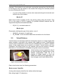
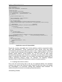
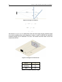
cheaply and easily, as LEGO did with his brilliant marketing campaign based on
AR-AR that stations were installed at toy stores for customers to have a box up
the camera and see the full 3D model on the screen, fully integrated into the live
video camera.
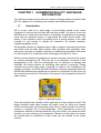
Figure 1.1 LEGO AR system
There are several main varieties of AR, and each is a huge subject in itself. The
books available today about mobile AR mainly focus on using the location
(GPS) and orientation (accelerometer) data from a mobile device to record the
content or integrate into a living landscape. These applications know your
smartphone camera is watching because they know where you stand and what
direction you are pointing your smartphone. Based on these data, the entries
are loaded either a centralized or other users can be overlaid on the scene
camera.
Chapter 1 Augmented Reality and Image Recognition
3
Another, but by no means exclusive, AR approach is to use the content of the
actual image captured by a camera to determine what you are seeing. This
technology is known as computer vision, for obvious reasons. The computer
processes each pixel of each video frame, evaluating the relationship of each
pixel with the neighbouring pixels over time and space, and identifies patterns.
Among other things, the current state of the art computer vision includes exact
algorithms for face recognition, identification of moving objects in the video, and
the ability to recognize known markers or visual patterns are specific to the
algorithm previously identified in a robust manner.
AR-based computer vision can be used in both contexts and non-mobile
contexts. It can be used to improve the location and orientation methods based
on AR, and can also be used to create AR applications that are not linked in any
way to a specific location. The computer-vision algorithm can be made to do
pattern recognition on packages, products, clothing, artwork, or any number of
other contexts.
1.2
Augmented Reality on Smartphones
The first versions of augmented reality are already here on some smartphones.
Smartphone owners can download an application called Layar3 that uses the
phone's camera and GPS capabilities to gather information about the
surrounding area. Layar app allows you to scan the public streets for vital
information, entertainment news, or networking possibilities. The program
essentially ‘layers’ the information about the landmarks and businesses on a
particular street.
Figure 1.2 Layar app
Another example is Google Sky Map4. This Android app will appeal to
stargazers and astronomers of all varieties. Simply point your phone at the sky
and identify a legion of constellations, stars and planets. If you move the
camera around, the information will change in accordance with the coordinates.
Excellent for recreational or educational use, Google Sky Map is a simple
3
Browser that allows users to find various items based upon augmented reality technology
4
Online sky/outer space viewer
4
Vuforia v1.5 SDK: Analysis and evaluation of capabilities
application of augmented reality used for complex tracking purposes. People
used to get paid annual salaries to do what this app can do in seconds.
1.3
Image or pattern recognition
Image recognition is the process of identifying and detecting an object or a
feature in a digital image or video. In machine learning, image or pattern
recognition is the assignment of a label to a given input value. However, pattern
recognition is a more general problem that encompasses other types of output
as well. Pattern recognition algorithms generally aim to provide a reasonable
answer for all possible inputs and to do "fuzzy" matching of inputs.
Pattern recognition is generally categorized according to the type of learning
procedure used to generate the output value. Supervised learning assumes that
a set of training data (the training set) has been provided, consisting of a set of
instances that have been properly labeled by hand with the correct output.
Unsupervised learning, on the other hand, assumes training data that has not
been hand-labeled, and attempts to find inherent patterns in the data that can
then be used to determine the correct output value for new data instances. A
combination of the two that has recently been explored is semi-supervised
learning, which uses a combination of labeled and unlabeled data (typically a
small set of labeled data combined with a large amount of unlabeled data).
Chapter 2 Vuforia Augmented Reality SDK
5
CHAPTER 2 VUFORIA AUGMENTED REALITY SDK
In this chapter it will be explained Vuforia’s SDK architecture and its main
elements. In addition it will be described the features of this new SDK in front of
its predecessor. The chapter will also show the library’s algorithm basics to
guarantee minimum recognition.
2.1
Introduction
Vuforia5 is an AR SDK for smartphones or other similar mobile device that
allows executes AR applications into a real time video obtained from these
devices. This software uses the capabilities of the computer vision technology
to recognize and make the individually tracking of the objects captured by the
video camera in real time. On the other hand, not all the objects will be
detected, and only a few detected objects may be tracked due mainly to the
mobile's CPU and GPU. In this project the used version of Vuforia SDK will be
the last available, in this case the 1.5 version.
The capability of Vuforia to image registration enables developers to position
and orient in the space the virtual objects, mainly 3D objects or other type of
media, in relation to real world images or video when these are viewed through
the camera of a smartphone. The virtual object then can track the position and
orientation of the real image in real time, so that the viewer’s perspective on the
object corresponds with their perspective on the real world target. In this way,
the virtual object or objects appears as if from another real world object.
The Vuforia SDK supports different types of targets, both 2D and 3D, including
multi-target configurations, marker less image targets and frame markers. The
SDK have another additional features like localized occlusion detections using
virtual buttons, image target selection in real time and the ability to reconfigure
and create target sets depending on the scenario.
But these not only will be made with Vuforia SDK to create AR applications. In
fact, Vuforia provides an API6 in Java, C++ and .Net languages through an
extension to the Unity3D7 game engine. Unity is an integrated authoring tool for
creating 3D video games or other interactive content such as architectural
visualizations or real-time 3D animations. Unity consists of both an editor for
developing/designing content and a game engine for executing the final
product.
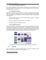
In this way, the SDK supports both native development for iOS and Android,
while also enabling the development of AR applications in Unity that are easily
portable to both platforms. AR applications developed using Vuforia are
5
AR SDK for mobile devices
6
Application Programming Interface
7
Cross-platform game engine with a built-in IDE
6
Vuforia v1.5 SDK: Analysis and evaluation of capabilities
therefore compatible with a broad range of mobile devices including the iPhone
(4, 4S and 5), iPad, and Android phones and tablets running Android OSversion
2.2 or greater and an ARM8v6 or 7 processor with FPU9 processing capabilities.
Figure 2.1 Development platforms
2.2
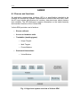
Architecture
The following section describes the main components in an application based
on Vuforia's SDK. These components are:
2.2.1 Camera
The camera singleton ensures that every preview frame is captured and passed
efficiently to the tracker. The developer only has to tell the camera singleton
when capture should start and stop. The camera frame is automatically
delivered in a device dependent image format and size.
2.2.2 Image Converter
The pixel format converter singleton converts between the camera format to a
format suitable for OpenGL ES10 rendering and for tracking (e.g. luminance).
This conversion also includes down-sampling to have the camera image in
different resolutions available in the converted frame stack.
2.2.3 Tracker
The tracker singleton contains the computer vision algorithms that detect and
track real world objects in camera video frames. Based on the camera image,
different algorithms take care of detecting new targets or markers, and
evaluating virtual buttons. The results are stored in a state object that is used by
the video background renderer and can be accessed from application code. The
tracker can load multiple datasets, but only one can be active at a time.
8
Acorn RISC Machine
9
Floating-Point Unit
10
OpenGL for Embedded Systems
Chapter 2 Vuforia Augmented Reality SDK
7
2.2.4 Video Background Renderer
The video background renderer singleton renders the camera image stored in
the state object. The performance of the background video rendering is
optimized for specific devices.
2.2.5 Application Code
Application developers must initialize all the above components and perform
three key steps in the application code. For each processed frame, the state
object is updated and the applications render method is called. The application
developer must:
• Query the state object for newly detected targets, markers or updated
states of these elements
• Update the application logic with the new input data
• Render the augmented graphics overlay
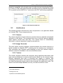
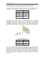
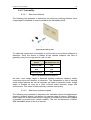
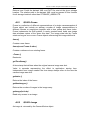
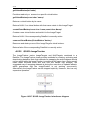
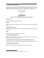
2.2.6 Target Resources
Target resources are created using the on-line Target Management System.
The downloaded dataset contain an XML11 configuration file that allows the
developer to configure certain trackable features and a binary file that contains
the trackable database. These assets are compiled by the application developer
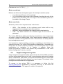
into the app installer package and used at run-time by the Vuforia SDK.
Figure 2.2 Data flow diagram of the Vuforia SDK in application environment
2.3
Features
The Vuforia SDK 1.5 supports Android devices running on Android 2.2 and
above, including Android ICS 4.0 and Jelly Bean 4.1.
11
eXtensible Markup Language
8
Vuforia v1.5 SDK: Analysis and evaluation of capabilities
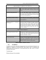
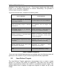
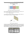
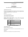
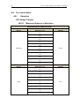
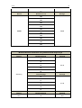
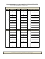
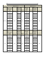
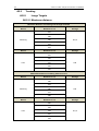
Improved Features in Vuforia 1.5 over Vuforia 1.0
Improved detection performance
The required detection time has been reduced by up to
40% in the image targets. Normally enough with a
second.
Improved tracking performance
The new SDK features several enhancements that
reduce jitter in the augmentations, speed up recovery
from tracking failures, detect targets at steeper angles
and track over longer distances.
Better tracking occlusion handling
Frame markers can now be partially occluded allowing
them to be picked up and used as game pieces during
the AR experience.
Improved maximum
image targets
This feature depends basically on the device hardware.
At the time of the 1.5 release (February 2012), the
most advanced GPU was the Adreno 220 and dual
cores CPU. With this hardware configuration, the limit
was improved until 5 maximum. Today is still better,
and with the Adreno 320 this number rises until 10 with
any kind of problems.
simultaneous
New Features in Vuforia 1.5
Video background texture access
The SDK now provides a simple and streamlined way
of accessing the video background texture. The colour
and video plane both image target as scene can be
changed or distorted in real time.
Runtime dataset swap
If the app needs to augment more than 60 images, now
the SDK can create multiple datasets using the webbased target management system and load the
appropriate dataset at runtime. Now is not necessary to
upgrade the app to change the target dataset.
Table 2.1 Features in different versions
2.4
Trackables
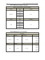
Trackable is the main class that represents all real world objects followed in six
degrees of freedom by Vuforia’s SDK. Each object when is detected and
tracked has a set of parameters. These parameters are: type, name, ID, status,
and pose information.
Trackable type
Defines the type of the trackable:
Chapter 2 Vuforia Augmented Reality SDK
9
UNKNOWN_TYPE - A trackable of unknown type.
IMAGE_TARGET - A trackable of ImageTarget type.
MULTI_TARGET - A trackable of MultiTarget type.
MARKER - A trackable of Marker type.
Trackable name / identifier
A twenty five character length string that identifies the trackable within the
database. Character set is composed by a-z, A-Z, 0-9,[ - _ ]
Trackable status
Each trackable has status information associated with it in the State object. This
object is updated when each camera frame is processed. The status is
characterized by an enum:
UNKNOWN - The state of the trackable is unknown. This is usually returned
before tracker initialization.
UNDEFINED - The state of the trackable is not defined.
NOT_FOUND - The trackable was not found
DETECTED - The trackable was detected in this frame.
TRACKED - The trackable was tracked in this frame.
Trackable pose
Current valid pose of a DETECTED or TRACKED trackable is returned as a 3x4
matrix in row-major order. The Vuforia SDK provides simple tool functions to
convert the Vuforia pose matrix into a GL model-view matrix and to project 3D
points from the 3D scene to the device screen.
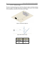
The Vuforia SDK uses right-handed coordinate systems. Each Image Target
and Frame Marker defines a local coordinate system with (0,0,0) in the centre
(middle) of the target. +X goes to the right, +Y goes up and +Z points out of the
trackable (into the direction from which it can be seen).
The origin of the local coordinate system of a Multi Target is defined by its
components. Image Target parts are transformed relative to this origin. The
reported pose of the Multi Target is the position of this origin, independent from
which individual part is tracked within the Multi Target. This feature allows a
geometric object (Ex. a box) to be tracked continuously with the same
coordinates, even if other Image Target parts are visible in the camera view
Vuforia represents three types of trackables that inherit properties from its base
class. These trackables are image targets, multi targets and frame markers.
10
Vuforia v1.5 SDK: Analysis and evaluation of capabilities
Each trackable is updated when its frames are processed and the results are
passed onto the app into an object called the State object. For a more complete
understanding of the data flow between the app and the SDK please take a look
at the Vuforia Architecture represented in Figure 2.2.
2.4.1 Image targets
Image Targets, are images that the Vuforia SDK can detect and track. These
images do not need special black and white regions or codes to be recognized.
The Vuforia SDK uses a set of algorithms to detect and track the features that
are present into an image recognizing them by comparing these features
against a database known object. Once is detected, Vuforia will track the image
along the camera’s field of view.
Image targets are created on-line with the TMS12 from JPG or PNG input
images. Features extracted from these images are stored in a database and
used for run-time comparisons.
The Vuforia SDK can detect and track up to five targets simultaneously
depending on the load on the processor and GPU. The Vuforia SDK can hold
approximately fifty Image Targets in its resource database. The Vuforia SDK
can also swap datasets at run time so your application can hold many more
targets.
2.4.1.1
Datasets
A dataset is set of trackables downloaded from the target management system.
The SDK allows an app to load, activate, disable and unload groups of datasets
at runtime. Datasets can contain both Image Targets and Multi Targets.
With SDK version 1.5 it is necessary to load the dataset from the SD13 Card or
download it from the Internet at application runtime. Note that only one dataset
can be active. This active dataset is used by the ImageTracker to find and track
targets in the camera’s field of view.
Dataset loading requires some time and therefore it is recommended
background loading.
Prior to Vuforia SDK v1.5 the old QCAR SDK was limited to only one Dataset
that was statically compiled with the app. The Dataset configuration was stored
in the config.xml file.
12
Target Management System
13
Secure Digital
Chapter 2 Vuforia Augmented Reality SDK
2.4.1.2
11
Parameters
Target size
Target size is the actual size of the image target in 3D scene units. A developer
must specify this during the on-line creation of the trackable or in the dataset
configuration XML file. The TMS generates the dataset configuration XML file,
but it can be modified. The size parameter is very important, as the pose
information returned during tracking will be in the same scale.
Virtual Buttons
Image targets can have one or more virtual buttons. The developer can query
the target for the number of associated buttons, cycle through a list accessing
each individual virtual button and check their associated status. Virtual buttons
can be dynamically added and deleted at run-time.
2.4.2 Multi targets
A multi target consists of multiple image targets that have a spatial relationship.
When the camera detects one of the parts of a multi target, all the others can be
tracked if their relative position and orientation is known. Completely field of
view of multi-image is not needed in Vuforia to track it if one of its parts is
partially visible. The difference between multiple individual image targets and
multi targets is that the second one performs one single trackable with one pose
information.
The image targets that make up a multi target are created with the TMS from
JPG or PNG. Input features extracted from these images are stored in a
database and used for run-time comparisons. The spatial relationship of the
individual parts is stored in the dataset configuration XML file using simple
transformations.
Multi targets can be created in two ways:
I.
Directly with the on-line TMS
II.
At run time through a well-defined set of APIs. Parts can be added or
removed, and their spatial configuration can be changed.
2.4.2.1
Parameters
Parts of a multi target are transformed in a common coordinate system. At runtime the origin of this coordinate system within the multi target is returned as
pose information. Thus all individual image target parts are placed with
translation and rotation within this system.
Multi image target parts have the following parameters:
Part name / identifier
12
Vuforia v1.5 SDK: Analysis and evaluation of capabilities
A twenty five character length string that identifies the part within the multiple.
This name must be identical to one image target definition within the same
target dataset target. Character set is composed by a-z, A-Z, 0-9,[ - _ ]
Translation
This parameter translates the origin of an image target part by the defined
scene units along the x,y,z axes.
•
(x,y,z) translation in scene units measured along the three spatial axes.
Rotation
This parameter rotates the origin of an image target part by the defined angle.
Rotations are defined as a series of axis and angle pairs that are applied in
order. Several formats to define the rotations are allowed:
•
•
•
(x,y,z, angle deg) rotation in decimal degrees along an axis defined by
the vector (x,y,z).
(x,y,z, angle rad) - rotation in radians along an axis defined by the vector
(x,y,z)
(qx,qy,qz,qw) - quaternion to define rotation
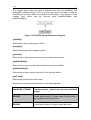
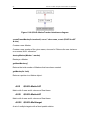
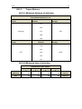
2.4.3 Frame Marker
The Vuforia SDK can track a special type of marker called frame marker. The ID
of a frame marker is encoded into a binary pattern along the border of the
marker image. The Vuforia SDK requires the frame and the binary pattern to be
almost entirely visible in the camera field of view during the recognizing
process.
The TMS does not generate frame markers. All 512
are distributed as an archive within the assets
folder of the Vuforia SDK.
Due to the relatively low processing power required
to decode the marker ID, all 512 frame markers can
be used in an application, and about five can be
detected and tracked simultaneously.
Figure 2.3 Frame Marker
2.4.3.1
Parameters
Frame marker has the following parameters:
Marker size
Target size is the actual size of the marker in 3D scene units. A developer
needs to specify this upon creation. The size parameter is important, as the
pose information returned during tracking will relate to the same scale. For
Chapter 2 Vuforia Augmented Reality SDK
13
example, if the marker is one unit wide, moving the camera from the left border
of the target to the right border of the marker will change the returned position
by one unit along the x-axis.
•
(x,y) size of the marker in scene units measured along the horizontal and
vertical axis of the marker.
Marker ID
Each frame marker encodes an ID in the binary pattern along the border. This
ID is in the range of [0-511] yielding 512 possible different markers and 3D
augmented objects associated with them.
•
ID [0-511] - encoded marker id.
Marker type
Enumerator defining the type of the marker, one of:
•
•
INVALID - A marker of invalid type.
ID_FRAME - An id-encoded marker that stores the id in the frame.
2.5
Virtual Buttons
Virtual buttons are developer-defined rectangular regions on image targets that
when touched or occluded in the camera view, trigger an event. Virtual buttons
can be used to implement events such as a button press or to detect if specific
areas of the image target are covered by an object. Virtual buttons are only
evaluated if the button area is in the camera view and the camera is steady.
Evaluation of virtual buttons is disabled during fast camera movements.
Virtual buttons can be created for any of
the two functions by defining them in the
dataset configuration XML file as a
property of image targets, or they are
added and destroyed at application runtime through a set of well-defined APIs.
Figure 2.4 Virtual button example
Each virtual button has the following parameters:
Button name / identifier
A string that uniquely identifies the button within the target.
Max string length: 25 characters
14
Vuforia v1.5 SDK: Analysis and evaluation of capabilities
Character set: a-z, A-Z, 0-9, [ - _ .]
Button coordinates
Buttons are defined as rectangular regions. A developer needs to specify:
•
•
(x,y) of the top left corner of the rectangle
(x,y) of the bottom right corner of the rectangle. Note that the units for the
button area in 3D scene units. The origin of this coordinate system is in
the middle of the Image Target.
Button sensitivity
'Sensitivity' refers to the 'responsiveness' of the button.
•
•
•
HIGH - Fast detection of the occlusion event, button will be very
'responsive' but may trigger some false positives.
MEDIUM - Balanced between fast response and robust detection.
LOW - The button needs to be occluded longer for an event to be
generated.
The Vuforia SDK allows adding and deleting virtual buttons to an image target
at runtime. Using this feature parts of the target become responsive to user
interaction, based on the applications needs. Virtual buttons are always defined
by a rectangle and a name.
It is important to note that adding, removing or modifying a virtual button is a
change to the state. The Vuforia SDK provides a callback that is executed every
frame after the tracker finished processing. The recommended way to make
modifications to trackables is to register a callback using the
QCAR::registerCallback() function and perform any modifications to the virtual
buttons configuration in QCAR_onUpdate(). 2.6
Target management system
Image recognition augmented reality apps built with the Vuforia SDK must have
a known target dataset that can be used to match targets captured with camera
device. Qualcomm's TMS offers a convenient web-based tool for Vuforia SDK
developers to create this known dataset from input images. This dataset is then
packaged and distributed with the application.
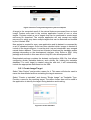
To access to the on-line TMS it is necessary to follow this link
http://ar.qualcomm.at/. Registration is required. Once log in, the server will
present the workspace. This page will contain all the projects.
Chapter 2 Vuforia Augmented Reality SDK
15
Figure 2.5 Vuforia’s target management system workspace
A target is the computed result of the natural features processed from an input
image. Feature sets used in the runtime application consist of one or more
targets. Projects contain a set of targets that can be combined to create target
resources for download. The runtime application will only accept one target
resource file, which may have multiple targets that can be detected and tracked
by the Vuforia’s SDK.
New project is created for every new application and its dataset is composed by
a set of uploaded images. Once has been decided which images is wanted to
include in the target resource, it must be pick it up and download it as a merged
natural feature dataset. There are two formats to download the trackable assets
package depending on the development interface: Unity Editor or SDK. Unity
package was chosen in this case due to Unity3D is the development IDE.
Downloaded package contains the dataset configuration XML file, that allows
configuring certain trackable features, and a binary file, holding the trackable
database. If a multi target is created using the web tool, it will automatically
include the appropriate definitions into the XML.
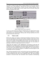
2.6.1 Create Image Target
Select "New Project" and provide a name for it. This name will also be used to
name the downloaded archive containing the target resources.
Select "Create a trackable" and choose "Single Image" as Trackable Type.
Provide a name for the resulting target. The name chosen here will be used in
the application to identify the target during detection and tracking.
Figure 2.6 Create trackable
16
Vuforia v1.5 SDK: Analysis and evaluation of capabilities
Enter the trackable name "surface" using the surface.jpg file. Also note that
the maximum length of the name is 25 characters.Finally must also define the
trackable width.
Figure 2.7 TMS tool
Once image target is uploaded it is possible to download it into a .zip or
.unitypackage extension and load it into the project source.
2.7
Image recognition considerations
As has been said before, one of the main purposes of Vuforia is the interaction
between real and virtual elements. To manage the virtual elements, Vuforia
uses a series of traces and patterns to distinguish the elements generated by
the online tool and the elements not generated by the TMS tool. Next it has
been explained the method used by Vuforia to recognise these different types of
elements, the image targets and the frame markers.
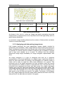
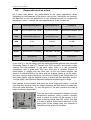
The TMS assigns a star rating for each image that is uploaded to the system.
The star rating reflects how well the image can be detected and tracked. The
star rating can vary among 0 to 5 for any given image. The higher rating of an
image target, the stronger the detection and tracking ability it contains. A rating
of zero would result in a target that would not be tracked at all by the AR
system. An image given a rating of 5 would be easily tracked by the AR system.
The developers recommend to only using image targets that result in 3 stars or
higher when submitted to the TMS system.
Enhancing the uploaded image target to yield higher feature count, while not
applying the same enhancements to the real target, will result in lower quality
detection and tracking. Any change made to the uploaded image target should
also be applied to the physical image target.
Image targets are created online with the TMS tool from jpeg or png input
images. Submitting an image target to TMS that has transparent regions is not
recommended because until now the system does not work properly with that,
in fact, only RGB image are supported. The targets created using this tool allow
the system to compute a digital fingerprint, allowing the client application to
identify the target in the real world. This fingerprint is composed by a series of
Chapter 2 Vuforia Augmented Reality SDK
17
distinctive features, or unique details in the image usually composed by areas of
high contrast.
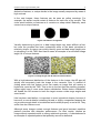
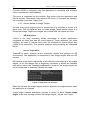
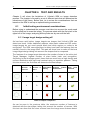
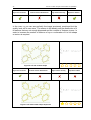
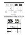
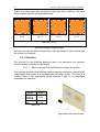
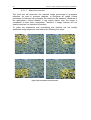
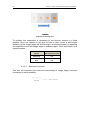
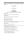
In the next images, these features can be seen as yellow crossings. For
example, the square would contain 4 features for each one of its corners. The
circle would contain no features as it contains no sharp detail. Basically, each
corner has a unique feature.
Figure 2.8 features recognition
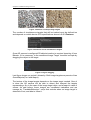
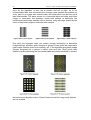
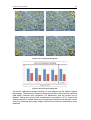
Visually determining a good vs. a bad image target may seem difficult at first,
but once the process has been understood some of the basic principles is
relatively simple. A person can quickly identify good and bad image target prior
to uploading it to the TMS. Next can be seen an example of an excellent image
target full of unique features.
Figure 2.9 image target with & without visible features
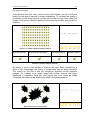
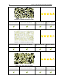
With a high balanced distribution of the features in the image, the AR app will
quickly and accurately track the image in the camera’s view. A method of
cutting areas with low feature count can create an image that will receive a
higher star count by the TMS. This is due to the fact that the resulting (smaller)
image might have a more even feature distribution. Better feature distribution
will enable the AR camera to track the target across a wide range angles and
zoom levels.
Like has been said before, is important to avoid cylindrical shapes, because it
have soft or round details containing blurred or highly compressed aspects do
not provide enough detail to be detected and tracked properly or not at all. They
suffer from low feature count.
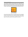
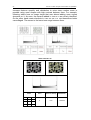
Although some images contain enough features and good contrast, repetitive
patterns interfere with detection performance. For best results, choose an
image without repeated motifs or strong rotational symmetry. A checkerboard is
an example of repeated pattern that probably cannot be detected.
18
Vuforia v1.5 SDK: Analysis and evaluation of capabilities
Figure 2.10 TMS tool
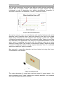
The other method to use a various image target is the multi target. This element
joins different image targets in only one.
Figure 2.11 Multi target example
To design properly a multi target element, these recommendations should been
followed. The depth is recommended to be at least around half of the width of
the front side. Since multi targets are detected and tracked as shapes, it is
important to highlight that the Vuforia SDK needs to find a certain amount of
features on the side of the multi target when the object is rotated.
Any kind of box in general is good for using as a multi target element. Since
multi targets are tracked as a single trackable as opposed to tracking multiple
single image targets simultaneously, performance is substantially improved.
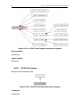
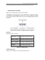
The last element is the frame marker that allows any image to be placed within
a predefined border that is bundled within the SDK. Unlike image targets, frame
markers are not generated by the online TMS. The number of built-in and
predefined frame markers is 512, representing frame marker IDs of 0 - 511.
The main use of these frame markers is as targets, because they are unique
and very simple to recognize by Vuforia. The marker consists of four areas,
where each has its specific function.
Chapter 2 Vuforia Augmented Reality SDK
19
Vuforia requires the frame and the binary pattern to be entirely visible in the
camera image for recognition. Once the frame marker is detected, one may
partially occlude the frame and the pattern. In actual usage, the frame or binary
pattern a good design of the frame marker printout can help to prevent partial
obstruction. Thus this guarantees the marker working properly. Below are some
examples of physical designs for markers that minimize occlusions by the user.
Figure 2.12 Frame Marker
An area around the black frame of the marker must be left free of graphical
elements. The black frame is used to recognize the marker in the environment
as seen by the camera during run-time. The ID area inside the frame encodes
the ID of the marker in a binary pattern. The design area is free to carry any
design. This area of the marker is not evaluated by the Vuforia SDK
20
Vuforia v1.5 SDK: Analysis and evaluation of capabilities
CHAPTER 3 VUFORIA FIELD OF APPLICATIONS
The following chapter describes Vuforia’s field of applications and its common
used scenario.
3.1
Vuforia field of applications
At first, when it was decided to study the Vuforia library, the thought was that
one of the main attractions was the automatic recognition of everyday objects
such as trees, tables, cars, etc. The ability to use the cloud, where objects could
be stored for later recognition, suggested that the user community help that
soon many objects were analysed and available remotely.
Once started the first tests, clearly became apparent the actual capacities and
needs of the library for recognition, which was actually for patterns and not for
objects. Given this feature, should think again about new applications that could
make use of this library, and how they should be used in these applications.
Currently, the main areas of use of augmented reality applications using the
SDK Vuforia are education, instructional, gaming and media & advertising. In
most of these areas, the applications obviously will be different, but they are
perfect scenarios to use an augmented reality application.
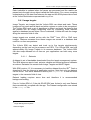
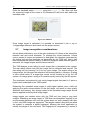
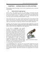
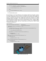
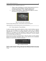
In the field of education, the possible
scenarios can be augmented reality apps in
museums, for example to letting visitors see
the unseen in the artworks or view information
of the artist. Another field can be the children’s
books; using an AR app they can come to life
with a new way of story-telling. Maybe the best
scenario is the scientific text book, because in
this area the augmented reality app can show
3D visualizations to help to understand
concepts or ideas like can be seen in the right
image. This example show a palaeontologist
book with a T-Rex illustration and a 3D model
of T-Rex in AR, using this technic the process
of understanding if much more natural.
Figure 3.1 Educational example
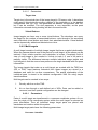
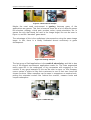
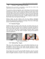
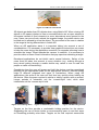
In the instructional field of application the most important applications are the
step-by-step instructions to assemble or troubleshoot a product. This feature
can be more useful when somebody is trying to assemble a product. In Figure 3.2
can be seen an example. Other applications are the interactive product manuals
and guided AR tutorials, where the instructions are augmented on the actual
product.
Chapter 3 Vuforia Field of Applications
21
Figure 3.2 Instructional example
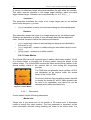
Maybe the most used environment is gaming, because many of the
applications are games. This fact is because there are a lot of different games
like shooters, strategy, virtual pets, puzzles, action, sports simulation, etc. In
games the only that needs the user is the image target, like can be seen in
Figure 3.3, and the “standard” game starts.
The advantage of this is the multiplayer interconnection using the same image
target. In fact, there is a library dedicated almost exclusively to game
development.
Figure 3.3 Gaming example
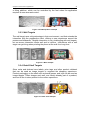
The last group of field applications is the media & advertising, and this is also
one of the biggest environment applications made for. The main augmented
reality apps are in the catalogues of big companies with engaging or fun
content. A very good example of this can be seen in Figure 3.4, this company
uses a series of sticks to help their customers to see in their own home the
chosen furniture. Other examples can be seen in magazines or readers book,
putting the extended content like “behind the scenes”, treasure hunts and
coupon redemption
.
Figure 3.4 IKEA AR app
22
Vuforia v1.5 SDK: Analysis and evaluation of capabilities
3.2
Common Target Usage Scenarios
Reaching into the real world to manipulate an object that only exists in the
augmented world can be a magical experience.
The experience of direct manipulation can be fascinating, but can also be quite
confusing for the final user. Must be taken in account that a user only has two
hands and one of them is usually occupied by holding a mobile device. Handeye coordination is also crucial – remember if a user’s focus is on a device, any
interaction with a free hand is blind interaction. Trying to coordinate both hands
can feel like use a body that is not yours. Tangible interaction can be a very
pleasant and intuitive method of interaction if it is done simply and usefully but it
also presents many user experience challenges.
Different targets can have different uses and have different advantages
depending on the situations in which they are used. Near-field AR applications
that aim at augmenting the immediate surroundings of the user can be largely
divided into the following usage situations:
3.2.1 Handheld Targets
Handheld targets like business cards, beer mats, and playing cards are very
good for use with mobile AR when the navigate pan and zoom functionality is
required for looking at an object. They are simple to manipulate and allow for
very accurate small movements. They can also be used as a controller for a
menu or list due to their ease of maneuverability. Business cards or playing
card sized targets are also well suited for tangible viewing and interaction in
mobile AR applications.
Figure 3.5 Handheld example
3.2.2 Tabletop/Floor Targets
Table top or floor targets (games, rugs, or floor-based advertising) are very
good targets for use in mobile AR, as this allows the user to take a much more
comfortable to hold the device. The screen remains horizontal or nearly
horizontal at a convenient angle and the camera is pointing downwards, making
the experience more comfortable.
These targets work very well for group tangible interaction, such as in a home
(board) gaming environment, and also act as a discreet passive experience
where no tangible interaction is required. A floor target can also be mounted on
Chapter 3 Vuforia Field of Applications
23
a tilting platform, which can be controlled by the feet when the application
required a more accused control.
Figure 3.6 Tabletop/Floor example
3.2.3 Wall Targets
The wall target uses a big advantage in their environment, and that extends the
interaction with the prospective client, offering a new experience around the
posters and billboards. Tangible interaction is very challenging with wall targets,
but on-screen interaction works well and is intuitive. Interactions with a wall
target can get tiring when pointing the phone at the wall for a long time.
Figure 3.7 Wall example
3.2.4 Retail Shelf Targets
Store racks and shelves have labels, price tags, and other product collateral
that can be used as image targets to augment the shopping experience.
Product packaging on the shelf such as board games, and toys can be used as
image targets. These images work well, are usually already part of a product,
and can tie the in-store product to the online experience.
Figure 3.8 retail shelf example
24
Vuforia v1.5 SDK: Analysis and evaluation of capabilities
CHAPTER 4 APPLICATION DEVELOPMENT
The following chapter shows how to easily create AR applications based on
recognition patterns using Vuforia’s Unity extension. The created application
has also been improved by adding new features based on scripts.
The chapter also shows the required considerations to guarantee application
usability.
4.1
Necessary software
Vuforia is an augmented reality SDK for mobile devices, and for this reason is
useless by itself, needs a software development environment or an IDE14 like
Eclipse, Unity, etc. In this case, the environment selected is Unity engine,
because is the easiest and compatible with the Vuforia library and with the
Android and iOS systems. The app developed in this project is only for Android
devices and it will be only used as a tool to test.
During the development of the augmented reality application, different elements
will be needed and normally there will be modeled in 3D. Obviously Unity can
manage 3D elements, but the tool that has been chosen is Blender 3D due to
its simplicity.
In conclusion, as mentioned, the app is going to be made using Vuforia
Android SDK under Unity3D IDE. Either one App 3D models are built using
Blender 3D software tool.
4.1.1 Unity3D
Unity is a fully integrated development engine that provides rich out-of-the-box
functionality to create games and other interactive 3D content. Unity can be
used to assemble art and assets into scenes and environments; add lighting,
audio, special effects, physics and animation; simultaneously play test and edit
games, and when ready, publish to your chosen platforms, such as desktop
computers, iOS, Android, etc. In the other hand, the Vuforia extension for Unity
enables detection and tracking functionality in the Unity IDE and allows to easily
creating AR applications and games.
Before start to use Vuforia is necessary to install Unity, because as mentioned
above Vuforia is only a library. For the Unity installation simply follow the steps
in the install file. In this case, the OS for the development has been Windows
and the url that can be used to download the program is
http://unity3d.com/unity/download/download-windows. Unity requirements are
described in the following table:
14
Integrated Development Environment
Chapter 5 Inmediate Incoming Future 2.0
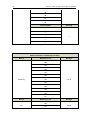
System
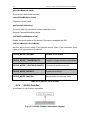
25
Microsoft Windows XP SP2 or later
Java Development Kit JDK
Android SDK
Android OS 2.0 or later
Device powered by an ARMv7 CPU
GPU support for OpenGL 2.0
Mobile Device
Table 4.1 Unity requirements
Vuforia unity extension
Once Unity is installed in the system, the next step is importing the Vuforia
libraries to Unity. Vuforia can work both in Android as in iOS, but for the
purposes of this project, the mobile OS will be only Android.
To do this, first download the Vuforia Android extension for Unity in this url
https://ar.qualcomm.at/user?&platform=Android&sdk_type=Unity&sys_name=wi
ndows&file_name=vuforia-unity-android-1-5-10.exe. The version used at the
time of writing this project is 1.5.
Once is downloaded the Vuforia extension, the next step is import the libraries
to Unity. To make this, simply open the navigation bar -> Menu -> Assets and
click in Import Package -> Custom Package. A new window will be open, go to
the Vuforia folder and select all the files inside. Now all the augmented reality
elements are available in Unity.
4.1.2 Blender 3D
Blender is a free and open-source 3D computer graphics software product used
for creating animated films, visual effects, interactive 3D applications or video
games.
Figure 4.1 Blender environment
Blender provides a broad spectrum of modeling, texturing, lighting, animation
and video post-processing functionality in one package. Through its open
architecture, Blender provides cross-platform interoperability, extensibility, an
incredibly small footprint, and a tightly integrated workflow. Blender is one of the
most popular open source 3D graphics applications in the world.
26
Vuforia v1.5 SDK: Analysis and evaluation of capabilities
Blender can be used to create 3D visualizations, stills as well as broadcast and
cinema quality videos, while the incorporation of a real-time 3D engine allows
for the creation of 3D interactive content for stand-alone playback.
The
link
to
download
the
latest
version
http://www.blender.org/download/get-blender/
and
the
http://wiki.blender.org/index.php/Doc:2.6/Manual
of
user
Blender
manual
Blender unity export
Unity natively imports Blender files. This works only using the Blender FBX
exporter, which was added to Blender in version 2.45. For this reason, you must
update to Blender 2.45 or later. To get started, save the .blend file in the
project's Assets folder. When switch back into Unity, the file is imported
automatically and will show up in the Project View. To see the imported model
in Unity, drag it from the project view into the scene view. If you modify your
.blend file, Unity will automatically update whenever you save.
4.2
How to create AR applications
As mention, the software used to develop AR Android apps was Unity 3D.
Vuforia’s Unity extension allows inexperienced developers to easily create AR
applications due to its fully integrated game engine reducing time and cost.
Moreover Unity 3D provides flexibility in project’s developing supporting iOS
and Android OS.
After Unity 3D is open, the project must be created selecting create new project
from menu bar file. It is indispensable to build the project importing all the
necessary assets first to guarantee image recognition and trackability in order
that the application works properly under Vuforia AR environment. It is for that
reason that the Vuforia Unity extension package is required. The installation of
this package is properly explained in 4.1.1. When the packages are imported, it
is possible to use all the characteristics of the Vuforia is SDK and the
application is able to recognise 2D and 3D objects.
4.2.1 Project Scenes
Once the project is created, Unity structures it into scenes. Every scene is like a
game level and is loaded when required. Think of each unique Scene file as a
unique level. In each Scene, you will place your environments, obstacles, and
decorations, essentially designing and building your application in pieces
Application menu is considered a scene too and its function is to manage the
application different scenes. Scenes that use device’s camera as AR camera
launch the capture process, define the tracker and execute its renderization. AR
Cameras are the eyes of the application. Everything the player will see is
through AR camera. You can position, rotate, and parent camera just like any
other GameObject.
4.2.2 UI: Main Menu Scene
The following point will show developers how to create a menu scene manager
Chapter 5 Inmediate Incoming Future 2.0
27
As said, application main menu handles the screen button events at GUI15 and
manages the different scenes.
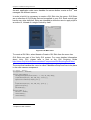
In order to build it is necessary to create a GUI Skin into the scene. GUI Skins
are a collection of GUI Styles that can be applied to your GUI. Each control type
has its own style definition. Skins are intended to allow the user to apply style to
an entire UI, instead of a single Control by itself.
Figure 4.2 UI Main menu
To create a GUI Skin, select Assets->Create->GUI Skin from the menu bar.
GUI Skins are part of the Unity GUI system. For more detailed information
about Unity GUI, please take a look at the GUI Scripting Guide
http://docs.unity3d.com/Documentation/Components/GUIScriptingGuide.html.
The script that handles the menu is called "MainMenuScript"and has to be place
in the main camera component.
var newSkin : GUISkin; var logoTexture : Texture2D; function theFirstMenu() { GUI.BeginGroup(Rect(Screen.width / 2 -‐ 150, 50, 400, 600)); if(GUI.Button(Rect(55, 100, 180, 80), "Start")) { Application.LoadLevel("teapot_fire"); } if(GUI.Button(Rect(55, 350, 180, 80), "Quit")) { Application.Quit(); } GUI.EndGroup(); } function OnGUI () { GUI.skin = newSkin; theFirstMenu(); } theFirstMenu(); } 15
Graphical User Interface
28
Vuforia v1.5 SDK: Analysis and evaluation of capabilities
Function OnGUI is executed once the application is launching and executes
menu’s construction theFirstMenu().
The menu is composed by two buttons. Quit button ends the application and
kills its process. Start button executes the AR scene. In this case, as example,
the launched scene was “teapot_fire”.
4.2.3 Scenes based on Image Targets
As said, every Unity project is set of scenes and it is operation is similar to a
game level. Will be explained how to create Image Target based scenes It is
known that Image Targets are images that Vuforia SDK can detect and track.
AR interaction
Vuforia in its Unity extension allows developers to create applications
composed by items that had AR world featured. These attributes, set using
scripting, let users to interact freely with the modelled 3d items without any
mobile touch interaction. The features achieved using scripting are described
below.
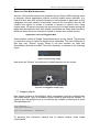
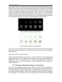
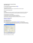
Scene I Teapot&Fire
Teapot&Fire scene contains all the necessary objects that perform an AR
environment. The application is composed by two Image targets and one AR
camera.
AR camera is the object responsible of the detection and tracking of the image
targets. Is for that reason that is absolutely necessary to define the datasets
that will be load in the "DataSetLoadBehaviour" script or the image targets will
not be interpreted. In this case "Stones and chips".
Figure 4.3 Data Set Load selection
Data Set includes the image targets and the algorithm to recognise them when
the application is executed.
Image target creation description process is shown in 2.6.1 Create Image
target. At the end, the app contains two image targets, “stones” and “chips”.
Chapter 5 Inmediate Incoming Future 2.0
29
Figure 4.4 Stones and Chips image targets
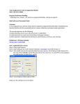
The number of simultaneous targets that will be tracked must be defined too
and depends on mobile device GPU specifications shown in 2.3.3 Features.
Figure 4.5 Number of max simultaneous targets
Once AR camera is configured 3D objects insertion is required importing it from
Blender, if it is necessary, to the convenient Image Target. Insertion is simple by
dragging the object to the target.
Figure 4.6 figure dragging
Last figure shows our project’s hierarchy. Both image targets are parents of two
GameObjects(Fire1 and teapot).
The texture of the image targets depends on the image target created. Once it
is done the AR camera will be able to detect and interpret the targets
representing a fire in the case of the image target chips, and a teapot in case of
stones. As said before, these images are considered trackables and are
manage by “TrackableBehaviour” script that controls when an image target is
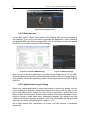
detected or lost, and able to follow it.
30
Vuforia v1.5 SDK: Analysis and evaluation of capabilities
Figure 4.7 teapot application example
Previously is described how to configure the necessary assets to recognise an
image target and display it is corresponding 3D object element. These elements
can be manipulated to alter their physical and spatial characteristics or cause
some events that were handled by scripts.
A. Proximity event
Image targets proximity events interaction can be handled using scripting. For
example, two different image target, once detected, can interact between them
and produce some alteration in its 3D modelled items. In this application when
the distance between stones and chips image targets is less than 20 world units
triggers an event script that produces steam.
Remembering project’s hierarchy teapot object has as a child a particle emitter
called “Fluffy Smoke” The script responsible of the steams emission
“Bolingbehaviour.cs” has to be placed at this emitter. It is very important to
define at Unity Inspector window script attributes.
Figure 4.8 script attributes
Heating distance defines the minimum distance required in world units. (20)
from the teapot and Fireplace is the GameObject (Fire1) which interacts
using UnityEngine; using System.Collections; [RequireComponent(typeof(ParticleEmitter))] public class BoilingBehaviour : MonoBehaviour { public float heatingDistance = 0.0f; // set in inspector public GameObject m_Fireplace = null; // set in inspector private GameObject m_Teapot = null; void Start () {m_Teapot = this.transform.root.gameObject;} void Update () { float teapotToFireDistance = Vector2.Distance(new Vector2(m_Teapot.transform.position.x, m_Teapot.transform.position.z), new Vector2(m_Fireplace.transform.position.x, m_Fireplace.transform.position.z)); Chapter 5 Inmediate Incoming Future 2.0
31
Debug.Log ("Distancia: "+teapotToFireDistance); if (teapotToFireDistance < heatingDistance) { this.particleEmitter.emit = true; } else { this.particleEmitter.emit = false; }}} B. Virtual button event
As said before in 2.5 Virtual Buttons are developer-defined rectangular regions
on Image Targets that when touched or occluded in the camera view, trigger an
event. In this application, there is a large virtual button that produces the steam
emission when is pressed. The script that controls the emission is called
“VirtualButtonEventHandler.cs” and has to be placed at “Stones.” Image Target.
The Virtual button is called “Start” and is a child of “Stones” too. All the possible
actions that can be done with the virtual button are refered at SDK’s script
“VirtualButtonBehaviour”.
using UnityEngine; public class VirtualButtonEventHandler : MonoBehaviour, IVirtualButtonEventHandler { private ParticleEmitter mSteamEmitter = null; void Start() { VirtualButtonBehaviour[] vbs = GetComponentsInChildren<VirtualButtonBehaviour>(); for (int i = 0; i < vbs.Length; ++i) { vbs[i].RegisterEventHandler(this); } mSteamEmitter = GetComponentInChildren<ParticleEmitter>(); if (mSteamEmitter) mSteamEmitter.emit = false; } public void OnButtonPressed(VirtualButtonBehaviour vb) {int i=0; if (mSteamEmitter) mSteamEmitter.emit = true; } public void OnButtonReleased(VirtualButtonBehaviour vb) { if (mSteamEmitter) mSteamEmitter.emit = false; } Figure 4.9 Virtual button app 32
Vuforia v1.5 SDK: Analysis and evaluation of capabilities
Device or Real World Interaction
As seen, AR world interactions are possible using Vuforia is SDK allowing users
to manage Vuforia applications without touching mobile device interface .It is
logical to think then that devices interaction is summarized in application is GUI
navigation once the camera is launched. However the interaction with the 3D
models from device is screen is possible in camera is capture time, using
scripts again. 3D objects normally are previously set to image targets during the
application development and their spatial coordinates are static and referred to
world but these items can created or altered in runtime from mobile screen.
Application scene II Draggable Ball
As said before create an Image Target based scene is very simple. The process
to create the scene is similar to the previously described. The main difference is
that now only “Stones” Image Target is set and contains as child one
GameObject textured as a Ball. The scene hierarchy is showed in the following
figure:
Figure 4.10 hierarchy of app
Now when the “Stones” are detected a football appears into the scene.
Figure 4.11 Draggable example app
C. Dragging objects
New scene contains a GameObject which coordinates could be modified from
the mobile device. Only is necessary screen touching and drag the football. To
achieve this GameObject has to be defined as movable containing the script
“MovableObject.sc”.
using UnityEngine; using System.Collections; public class MovableObject : MonoBehaviour { } To perceive this interaction camera has to contain another script called
“InputHandle”.
Chapter 5 Inmediate Incoming Future 2.0
using UnityEngine; using System.Collections; public class InputHandler : MonoBehaviour { private Ray m_Ray; private RaycastHit m_RayCastHit; private MovableObject m_CurrentMovableObject; private float m_MovementMultipier = 10f; void Update () { if(Input.touches.Length == 1) { Touch touchedFinger = Input.touches[0]; switch(touchedFinger.phase) { case TouchPhase.Began: m_Ray = Camera.mainCamera.ScreenPointToRay(touchedFinger.position); if(Physics.Raycast(m_Ray.origin, m_Ray.direction, out m_RayCastHit, Mathf.Infinity)) { MovableObject movableObj m_RayCastHit.collider.gameObject.GetComponent<MovableObject>(); if(movableObj) { m_CurrentMovableObject = movableObj; } } break; case TouchPhase.Moved: if(m_CurrentMovableObject) { m_CurrentMovableObject.gameObject.transform.Translate(Time.deltaTime m_MovementMultipier * new Vector3(touchedFinger.deltaPosition.x, touchedFinger.deltaPosition.y)); } break; case TouchPhase.Ended: m_CurrentMovableObject = null; break; default: break; } } }} 33
= * 0, Application scene III. DynamicBall
Previously sections described that Vuforia platform enables augmented reality
(AR) app experiences. These experiences reach across most real world
environments, giving mobile apps the power to see. Image recognition allows to
our mobile device process and recognizes images and showing a set of AR
prefabs (game objects, virtual buttons, etc.) in AR world. As seen, these
elements normally are static, linked to a trackable and are shown when image
target is detected. But prefabs can be loaded and destroyed dynamically at
runtime optimizing memory usage. For example, the following example
describes how to create AR elements at runtime at a given position.
D. Creating elements at runtime.
First of all the environment has to be set. As explained before, the trackable
used into the scene was Stones Image Target but this time does not contain
any GameObject, as conclusion nothing was modelled when detected. To
create elements at runtime is necessary script intervention.
Instantiating Prefabs
34
Vuforia v1.5 SDK: Analysis and evaluation of capabilities
Prefabs come in very handy when you want to instantiate complicated game
objects at runtime. The alternative to instantiating Prefabs is to create game
objects from scratch using code. Instantiating Prefabs has many advantages
over the alternative approach: A Prefab can be instantiate from one line of code,
with complete functionality. Creating equivalent game objects from code takes
an average of five lines of code, but likely more. It can be set up, tested, and
modified quickly and easily in the Scene and Inspector. Prefabs can be
changed without changing the code that instantiates it. In order to transform
GameObjects to Prefab create a new Prefab in Unity (Right click in project
window-->create Prefab) and drag GameObject to the create prefab
Once the prefab is created is necessary to define the script that allows to
instantiate elements at runtime at AR camera object.
using UnityEngine; using System.Collections; public class InputHandler : MonoBehaviour { public GameObject bola; float xw=0; float zw=0; void Update () { if(Input.touches.Length == 1) { Touch touchedFinger = Input.touches[0]; switch(touchedFinger.phase) { case TouchPhase.Began: float x=touchedFinger.position.x; float y=touchedFinger.position.y; Debug.Log("Posicion de pantalla x: " +x); Debug.Log("Posicion de pantalla y: " +y); if(x>300){ xw=50; } if((x<300)&&(x>150)){ xw=0; } if(x<150){ xw=-‐50; } if(y<266.6){ zw=35; } if((y<533.3)&&(y>266.6)){ zw=0; } if(y>533.3){ zw=-‐35; } Debug.Log ("Posicion en el mundo ("+xw+","+zw+")"); GameObject b = (GameObject)Instantiate (bola,new Vector3(zw,0,xw),Quaternion.identity); ImageTargetBehaviour itb = GetComponent<ImageTargetBehaviour>(); b.transform.parent=itb.transform; ImageTargetBehaviour.CreateVirtualButton("boton",new Vector2(0,0),b); break; case TouchPhase.Ended: break; default: break; }} }} It is necessary to define GameObject (bola) as attribute
Creating and deleting virtual buttons at runtime
Chapter 5 Inmediate Incoming Future 2.0
35
Virtual buttons can be created at runtime too
I.
II.
Create a new virtual button for a given image target at runtime by
calling the CreateVirtualButton member function on the
corresponding instance of your ImageTargetBehaviour.
Destroy a virtual button by calling DestroyVirtualButton, which is
also defined in ImageTargetBehaviour.
Figure 4.12 Virtual button example app
Previous script uses dynamic virtual creation at the following line:
ImageTargetBehaviour.CreateVirtualButton("boton",new Vector2(0,0),b); 4.2.4 Scenes based on Frame Markers
In order to use the frame markers objects in Unity it must be taken in account
only the ID of the image. As it been said before, there are 512 different
schematic (ID 0 to ID 511) in the frame markers, every one with a different
marker ID. The marker ID is the identifier for Vuforia, and the final user can
choose the marker ID number for every different schematic. The only condition
is to avoid the duplicate marker ID’s.
At the moment of make and build the app, it has been keep in mind the relation
between the ID and the schematics, that is to say, make sure the combination
between a certain marker ID with its schematic.
Figure 4.13 Define marker ID
Finally, to use the frame marker, simply print the desired schematic and view it
with the device camera. The app will show the AR element above the printed
image.
36
Vuforia v1.5 SDK: Analysis and evaluation of capabilities
Figure 4.14 Example of use
4.2.5 Build and run
In this step, and if it does not do before, the Android SDK must be installed in
the machine. If not, unity is not able to generate the application. When installing
the Android SDK can choose several APIs, but in this case you should choose
the API 4.0.3 or higher using the SDK Manager.
Figure 4.15 Android SDK Manager
Figure 4.16 Build settings
Now, is time to test the application connecting the smartphone to PC via USB.
Unity recognises the device and automatically install and launch the application.
Only need to choose the operating system of the target device and click in Build
and Run.
4.2.6 Applications logs & debug
When any mobile application is being developed is need to be tested, and for
this is essential to read the interaction between the device and the app. In this
point, and talking about Vuforia for Unity there is a problem, Vuforia does not
able to make this interaction at the current version. During the realization of this
project, several e-mails have been exchanged between the authors and the
Vuforia’s developers and the answer is clear, this functionality will be launched
with the 2.0 version (actually the last version is 1.5).
As is says before, this functionality is crucial, and the solution is explained
thereupon.
Chapter 5 Inmediate Incoming Future 2.0
37
The solution adopted was as follows; use the ADT plugin for Eclipse mobile
developers to read the different logs and messages from the smartphone. ADT
plugin extends the capabilities of Eclipse to quickly set up new Android projects,
create an application UI, add packages based on the Android Framework API
and debug applications using the Android SDK tools. This last part is the main
advantage to be exploited.
The main steps to install the necessary software are the next:
1 – Install the Java Development Kit if necessary
2 – Install Eclipse Mobile Developers
3 – Install the ADT plugin for Eclipse
4 – Update Android SDK if necessary.
4.3
Vuforia license
For the developers it is very important to know the license that use Vuforia, if
there are any. In this case, the Vuforia SDKs are all free, there are not licensing
fees. Even if the purpose is the commercial use for applications under Android
or/and iOS platforms, the cost of it is free. In the other hand is important to
remark that Vuforia or any other Qualcomm software is subject to the terms of
the GPL, AGPL, LGPL, EUPL, APSL, CDDL, IPL, EPL, MPL, or such other
open source license.
But there are some conditions for this free use, and all are detailed explain in
the
License
agreement
that
can
be
found
in
https://developer.vuforia.com/legal/license. The most important parts in the
license agreement is the part 8 (the mandatory end-user license agreement
clause) and the part 2.2 (use restrictions). Furthermore, the application only can
contain the logo, the name or any kind of reference to Vuforia with the explicit
permission of Qualcomm, due to the rules for these cases of Qualcomm.
There is only need to pay for the use of cloud storage, because this service is
property of Qualcomm and should be used by legal engagement.
4.4
Best Practices for Well-Created Apps
The following point describes how users should interact with an AR application
made with Vuforia to get the best performance and considerations that must be
taken into account during the application development to made it usable.
Vuforia user interface allows free method for viewing 3D objects, which
promotes natural interactions and the possibility of incorporating movement into
the interaction of either hand or the whole body.
38
Vuforia v1.5 SDK: Analysis and evaluation of capabilities
Figure 4.17 3D free enviroment
3D objects are better than 2D objects when using Mobile AR. When viewing 3D
objects in 3D space is better to have a moveable device as an open window to
this space instead of fixed viewpoint so more dimensions were opened to the
user. Users can move freely around the targeted image, the mobile device can
be tilted and is allowed to move the object. The movement of the user in relation
to the target is the big differentiator in mobile AR
When an AR application starts it is important taking into account a set of
considerations. It is necessary to provide clear graphical instructions on screen
to help the users during the application execution, for example informing how to
orientate the Image Target towards the camera. In addition, it is necessary to
provide outline or some visual information that pop-ups when detecting a target.
Developed applications do not inhibit user’s normal behavior. Safety of the
users must be taken into account in every situation (e.g., walking through a
busy street looking through a mobile device may cause a user to walk into
people or traffic unintentionally).
Considering how the user will grasp and hold the device must be considered
planning for the appropriate pose for the appropriate situation. Different poses
might fit different purposes and types of interactions. When using AR
applications, the arms of the user can feel tired very quickly when holding up
the device. Often the pose required is similar to taking a picture with a camera.
Longer periods of interaction suit the ‘console-style’ hold, while short
interactions suit the ‘camera-style’ hold.
Figure 4.18 Looking down
Figure 4.19 Standing over table
Figure 4.20 Standing on wall
Targets on the floor provide a comfortable holding position for the device.
Suggesting the use of device holder or recommending users to rest their arms
on something probably relax them. Targets on the wall required camera-like
Chapter 5 Inmediate Incoming Future 2.0
39
holds which long term exposures provide arm fatigue. Is for that reason the use
of such applications should be brief.
To provide an optimal experience, the augmentation should be visible to the
user. Losing a target is one of the most irritating issues when using an AR app
but can be easily compensated if it is considered from the start giving some
indications to users that have lost the target.
Image Target prints can be easily obtained by the user if the application is not
designed around an existing object or product, for example providing a link to
the target in app description text
Reaching into the real world to manipulate an object that only exists in the AR
world can be a magical experience. Direct manipulation can be fascinating, but
can also be quite confusing for the user. User only has two hands and one of
them is usually occupied by holding a mobile device. Hand-eye coordination is
also crucial. Tangible interaction can be a very pleasant and intuitive method of
interaction if it is done simply and usefully. It is required to use small targets
with simple one-handed operation moving one at a time. On the other hand, it is
not recommended to mix tangible and on-screen interactions due to can be
confusing.
On screen interaction is the most obvious, useful, intuitive, and simple method
for normal or functional tasks. Is for that reason that onscreen user interface
should be clear and simple.
Virtual buttons are usable with mobile AR and work well in simple tasks such as
changing color. Virtual buttons provide a nice delightful surprising interaction
when understood by the user.
40
Vuforia v1.5 SDK: Analysis and evaluation of capabilities
CHAPTER 5 INMEDIATE INCOMING FUTURE 2.0
As seen during the development of this project Vuforia SDK brings to users an
incredible AR experience that allows to them see and interact to the unseen.
The 1.5 libraries had improved detection and trackability robustness of its
predecessor. At the end of the year 2012 Qualcomm announced the
development of a new release, Vuforia 2.0 SDK, from Qualcomm's Austria
Research Center GmbH. The platform leverages the power of the cloud and
delivers enhanced features and toolsets that enable the creation of richer, more
relevant and more engaging AR experiences.
This 2.0 commercial release includes the following features:
•
•
•
•
•
•
•
•
Cloud Recognition - image recognition against databases containing
over one million images
User-defined Targets - empowers users to define their own image
targets to launch the app experience using everyday images
Video playback
Support for Play Mode in Unity – enables developers to code, test
and debug in real time using a webcam to simulate the AR
experience
Support for using the front camera
Support for multiple active device databases
Improved tracking robustness
Combined iOS and Android plugins in the Vuforia Extension for Unity
5.1
Developer Workflow. Local database vs. Cloud
database
After creating an account in the TMS, the developer is presented with a choice:
use device based databases or, new 2.0 feature, cloud based databases.
Developers will not be able to convert a database to the other type later on, so it
is absolutely necessary to be clear on which capabilities app needs.
Device databases provide Vuforia applications with a locally accessible
database of image targets.
If it is known what the application will be expected “see”, and the target set of
images is less than 100 images, then a local device database is the right
solution. Device database use cases include promotional campaigns for a
specific set of products or print material, anything that will be identified and
scanned with a lower set of images. Device databases will receive more
immediate responses since the images are stored locally.
Cloud databases provide Vuforia applications with a large number of targets.
Cloud databases are stored in the Internet and support over a million image
targets.
If the application supports a retail or catalogue use case where there are more
than 100 images or the images are being updated frequently, then a cloud
Chapter 5 Inmediate Incoming Future 2.0
41
database is the right solution for you. Cloud image targets may take a little
longer to be identified (depending on network connectivity), but provides a
strong image recognition capability.
To aid with this decision, consider the following table:
Device Database
Cloud Database
Limited to 100 targets per downloaded
device target database
>1 million targets in the cloud database
Allows downloading targets in different
combinations
One database with all images and
metadata
Downloaded targets only for detection,
no metadata support
Targets retrieved by cloud recognition
can carry up to 150kB of metadata
Network connection on end user device
not required for detection
Network connection on end user device
required for recognition, network traffic
for cloud recognition
Run-time detection response time within
2-3 frames
Response time up to 3 seconds,
depending on network connectivity
Multiple databases can be active (each
with maximum 100 targets)
Recognition on maximum
targets active at any time
Free
Free and Paid, depending on usage
1
million
Table 5.1 databases comparison
Once you have decided between the two methods, then the following chart will
guide you in the creation of your Vuforia Augmented Reality application.
5.2
User-Defined Targets
The User-Defined Targets application demonstrates how to create a target
directly on a device from within an application. End users are now able to
display augmentations without the need for a predefined physical target. The
sample shows how to capture a target and augment a teapot on top of the
image
42
Vuforia v1.5 SDK: Analysis and evaluation of capabilities
Figure 5.1 user defined target
5.3
Video Playback
One of the newest characteristics of the 2.0 SDK is the video playback. This
feature allows users embed any h264 video into the application, but this video
will be only visible when the AR camera detects the chose image target. This is
very interesting, because it allows the developer to hide the video and play it
only just above the target, resize in real time according to the user's position
and the target image.
This sample application shows how to play a video in AR mode. Devices that
support video on texture can play the video directly on the image target. Other
devices will play the video in full screen mode.
The process to create the example is like that made before, but in this case
adding a new characteristic into the image target (video). After, it should be
added the script VideoPlaybackBehaviour.cs, and in it can be found the path for
the video to show and the image with the play icon (Keyframe Texture).
Figure 5.2 video script configuration
Once is done, the application in the smartphone shows above the image target
chosed (in this case stones) the image added in the Keyframe Texture with the
play icon. If play button is pressed, the video starts and can track the image
target.
Figure 5.3 Video playback example
Chapter 5 Inmediate Incoming Future 2.0
5.4
43
Unity Play Feature
Augmented scenes created for a Vuforia app can be tested in the Unity Pro IDE
using Play mode. Play mode functions as it would for any application developed
in Unity, allowing rapid editing and testing of your app. No special action to
enable Vuforia in Play mode is required.
Play mode is intended to be only an approximation of the actual on-device
experience.It is not an emulator and should not replace on-device testing during
development.In particular, tracking and rendering performance are likely to
differ from that seen on the device.
Using Play mode
1. To use Play mode with Vuforia, connect a webcam to your computer.
2. Select your AR scene from the Unity Project Browser.
3. [Optional] Click on the ARCamera object in the Hierarchy.
4. [Optional] In the WebcamBehaviour section of the Inspector, select the
camera you wish to use.
5. Start Play mode.
Now it can be seen the camera feed from the webcam in the Unity IDE.Placing
an AR target in the field of view of the camera causes detection and tracking to
occur as it does on a physical Android or iOS device. Once detected, the
augmentation rendered in the scene can be viewed.
44
Vuforia v1.5 SDK: Analysis and evaluation of capabilities
CHAPTER 6 TEST AND RESULTS
Chapter 6 will show the limitations of Vuforia’s SDK on image detection
process. The chapter is formed by a set of different tests that will determine the
robustness of the library. Before that, let is review the considerations that are
based on the SDK to set up an optimal testing environment.
6.1
Initial testing environment considerations
Before trying to understand the process must take into account the mode used
by the online tool to scan the image. The process starts with the first pixel in the
upper left of the image, analysing all the pixels row by row until the last.
6.1.1 Image target design making off
As has been said before, image targets are images that Vuforia’s SDK can
detect and track. Unlike traditional markers, data matrix codes and QR codes,
image targets do not need special black and white regions or codes to be
recognized. The SDK uses algorithms to detect and track the features that are
naturally found in the image itself. This part will show how to make off the best
image target design taking into account the shapes that is composed.
The features of an image target determine the number of stars in the online tool
Target Manager, highest number of stars better track and recognition.
According to the developer portal, these features must have a high density and
uniform distribution with high local contrast using no repetitive patterns. Taking
this into account, the first tests will determine the best shape.
Number
features
of
Number of
Stars
0
0
4
0
15
0
High feature
density
Uniform
feature
distribution
High local
contrast
Table 6.1 shapes comparison
As can be seen in the previous table, the maximum number of features is
obtained with the star shape; taking into account the number of corners. With
this test can show that the more corners have the image more features detect
Chapter 6 Test and Results
45
the target manager.
It can be seen that how many corners is the most suitable, but not of sufficient
quality for the lack of features in density distribution. To increase the quality of
recognition of the image need to multiply the number of ways (star) within the
image. It will follow a repetitive pattern in the same way multiply your number of
features.
Figure 6.1 IT with repetitive pattern features
High Local Contrast
Uniform Feature Distribution
High Feature Density
Repetitive Pattern
Table 6.2 repetitive pattern behavior
As shown in Table 6.2 the number of features (Nf) have been multiplied by a
factor of Ne. Surprisingly, the quality of image target has not been increased.
The reason for this fact is that the recognition algorithm avoids repetitive
patterns. So, creation of an image target with enough features and highly
distributed is imperative. Said this, next logical step is to create an image
composed with different star shapes and without a repeated pattern.
Figure 6.2 IT with custom shape
46
Vuforia v1.5 SDK: Analysis and evaluation of capabilities
High Local Contrast
Uniform Feature Distribution
High Feature Density
Repetitive Pattern
Table 6.3 star shape behavior
In the Table 6.3 you can see perfectly the image previously mentioned but the
quality level still in zero stars. The reason is the density and the distribution of it
is features that are not enough dispersed and the number of features is poor. In
order to increase the number of features of Figure 6.2 alteration of it is line shape
or texture is required.
Figure 6.3 IT with custom shape
High Local Contrast
Uniform Feature Distribution
Figure 6.4 IT with custom shape improved
High Feature Density
Repetitive Pattern
Chapter 6 Test and Results
High Local Contrast
47
Uniform Feature Distribution
High Feature Density
Repetitive Pattern
High Feature Density
Repetitive Pattern
Figure 6.5 IT with texture background
High Local Contrast
Uniform Feature Distribution
Table 6.4 improving shapes
For example, Figure 6.5 shows the rise of quality in star level by increasing the
number of features of Figure 6.3 and Figure 6.4 for example, increases this level
only modifying texture background. It is important to notice that the
improvement was reached only using a white background instead of black. The
reason is higher contrast. Recognition algorithm, as said before, executes a
horizontal sweep from left to right, and changes in image shades enhance this
process. Figure 6.5 improves the number of features in line shaping using dotted
line instead of continuous. But image stills not getting distribution and features
enough. Using an appropriate texture with a lot of shades like Figure 6.5
considerably raises it is rate in target management system because now is
provided with a good distribution and a high number of features.
As conclusion, target management system is mainly based in three properties:
shaping, shading and uniform feature distribution. Taking these conclusions into
account, next table shows the best trackable image targets designs.
48
Vuforia v1.5 SDK: Analysis and evaluation of capabilities
Figure 6.6 IT with 5 stars square shape
High Local Contrast
Uniform Feature Distribution
High Feature Density
Repetitive Pattern
High Feature Density
Repetitive Pattern
High Feature Density
Repetitive Pattern
Figure 6.7 IT with 4 stars square shape
High Local Contrast
Uniform Feature Distribution
Figure 6.8 IT with 4 stars ball shape
High Local Contrast
Uniform Feature Distribution
Chapter 6 Test and Results
49
Figure 6.9 IT with 1 star ball shape
High Local Contrast
Uniform Feature Distribution
High Feature Density
Repetitive Pattern
Table 6.5 finding the best shape
As shown in the Table 6.5, when an image has highly contrasting tones the
shapes which is composed are not so important due to the high density and it is
great feature distribution.
In conclusion, image shading determines the number of features that can detect
Vuforia in a well-done image.
6.1.2 Analysing and determining image tones
Last chapter describes the most appropriate images targets required to
guarantee good trackability. Main image features that provide good scoring at
target management system were high density and uniform feature distribution. It
is important to mention that the number of features gets increased in pictures
with a high tonal variation on it is pixels. To analyse how this variation
determines image target trackability an image histogram representation was
done.
An image histogram is a type of histogram that acts as a graphical
representation of the tonal distribution in a digital image. It plots the number of
pixels for each tonal value. By looking at the histogram for a specific image, a
viewer will be able to judge the entire tonal distribution at a glance. The
horizontal axis of the graph represents the tonal variations, while the vertical
axis represents the number of pixels in that particular tone. The left side of the
horizontal axis represents the black and dark areas, the middle represents
medium grey and the right side represents light and pure white areas. The
vertical axis represents the size of the area that is captured in each one of these
zones. Thus, the histogram for a very dark image will have the majority of its
data points on the left side and centre of the graph. Conversely, the histogram
for a very bright image with few dark areas and/or shadows will have most of its
data points on the right side and centre of the graph.
50
Vuforia v1.5 SDK: Analysis and evaluation of capabilities
The following images represent different tonal distributions histograms.
Figure 6.10 bitonal histogram
Figure 6.11 4 tones histogram
Figure 6.12 8 tones histogram
Figure 6.13 16 tones histogram
Figure 6.14 256 tones histogram
It is important to remember that Vuforia image recognition algorithm is based on
grey-scale tones, so colour chroma is not so important, only shading. Every
image is managed using its grey-scale information during the process.
Figure 6.15 colour test pattern
Figure 6.16 histogram with colour
Figure 6.17 b&w test pattern
Figure 6.18 histogram without color
As is seen, the same image in colour or grey-scales gives identical grey-scale
histogram. But which are the best tones to detect and track? Focusing on tonal
contrast, the aim is determine the most convenient shades for this purpose:
pitch blacked or highlighted ones. The result was obtained analysing an image
target composed with squared in three tones forms on it and comparing the
results in the target management system when the shades are altered.
Chapter 6 Test and Results
51
Table 6.6 and Table 6.7
As seen Table 6.6 and Table 6.7, shadow black tones seems to be better to detect
and track that light pure whites. In spite of this, not every tonal variation was
spotted. Mid tones changing were not perceived at all. If the making off of the
image target is performed using as a configuration three widely spaced tones
like Table 6.8 shows the score at target management system become increased.
Colour R
G
B
255
255
255
89
89
89
0
0
0
Stars Features density Distribution 2
normal
uniform
Table 6.8
52
Vuforia v1.5 SDK: Analysis and evaluation of capabilities
Increase features quantity and distribution to raise stars number score is
possible using more shapes with high contrast between them. For example,
following tables have an image target that was altered adding more square
elements on it. As seen, the squares added in Table 6.10 are clearly identified.
On the other hand newer elements in Table 6.9 and 6.10 are themselves better
camouflaged. The reason is the lower tone range between them.
Table 6.9 and 6.10
Colour R
G
B
242
242
242
89
89
89
0
0
0
Stars Features density Distribution 4
rich
Uniform
Table 6.10
Chapter 6 Test and Results
53
As a result, Table 6.10 is richer in features than the other two and consequently
high rated. But what is the minimal gamma range used at TMS to spot a shade
change? Is the same range for dark and light tones? To determine both minimal
ranges, two different images were processed at TMS. First one is composed by
a set of squares with shades that belongs to dark region over a pitch-black
background (0,0,0). Every square jumps ten tones from previous one situated at
its left. The same idea occurs at the second one but this time squares decrease
ten tones from light region over clear white background (255,255,255).
Figure 6.19 Min. dark tone range detection
Figure 6.20 Min. light tone range detection
As seen in the two above figures dark tones had less detection window (50)
than clear ones (60) at TMS, in conclusion are more accurate at pitch changes.
Dark detection
Image manipulation and histograms
Image editors typically have provisions to create a histogram of the image being
edited. Algorithms in the digital editor allow the user to visually adjust the
brightness value of each pixel and to dynamically display the results as
adjustments are made. Improvements in picture brightness and contrast can
thus be obtained.
6.1.3 Detection algorithm minimum requirements
Until now the underlying features of Vuforia is TMS were described to
guarantee good detection and trackability. This algorithm, as mentioned before,
is basically based on shapes with corners and tone changes, been the last one
the most important feature. When these conditions are spotted the algorithm
puts a marker on it. But this is done in each pixel? Is known that the sweep
54
Vuforia v1.5 SDK: Analysis and evaluation of capabilities
done by the algorithm is from top to bottom and left to right, so is not
unreasonable think that horizontal tone changes were spotted and marked on
every pixel of an image with vertical black and white pixel lines but the result
was unfavourable. The same occurs for a horizontal black and white pixel lines
image. In conclusion, the algorithm needs both sweeps to determine line
corners and mark image features. But in practice, using an image formed by the
fusion of last both images no features were marked.
Figure 6.21 1 pixel stripes
Figure 6.22 1 pixel stripes
Figure 6.23 1 pixel squares
One pixel tone changes does not contain enough information to determine
image features. Minimum pitch changes in groups of two pixels are required to
mark image features which are randomly set .If the algorithm processes Image
Targets composed by a groups in same color and size 15x15 pixels then
features marks positioning are more predictable and clearly identified at corners
As can be seen algorithm has a 15 pixel frame around the image were features
are not marked.
Chapter 6 Test and Results
6.2
55
Disposable devices to test
As it been said before, the performance of the same application varies
depending on the hardware of the device used to test. Taking this into account,
the best way to test the applications is use different devices to compare the
throughput. Table 6.11 shows the main specifications of the test devices.
Samsung Galaxy Note II
Samsung Galaxy S
HTC Desire
CPU
Exynos 4 Quad 4412 1,5GHz
Exynos 3110 1Ghz
Snapdragon QSD8250 1GHz
GPU
Mali 400 MP (quadcore)
PowerVR SGX 540
AMD Z430
RAM
2 GB
512 MB
512 MB
Android
4.1.1
2.3.6
2.2
Display
S-AMOLED 5,5” 720x1280
S-AMOLED 4” 480x800
AMOLED 3,7” 480x800
Camera
8 Megapixels
5 Megapixels
5 Megapixels
Table 6.11 Specification comparison
In the Table 6.11 can be clearly seen the deep similarities between two terminals
(Samsung Galaxy S and HTC Desire) both CPU and GPU are similar in their
capacity and performance. In the other hand, there is a last generation
smartphone with a quad core CPU and GPU with a massive improve of
performance in relation with the other two. In the two similar devices, the
amount of available RAM is the same and the Android version is not the same,
but has a common basis. Moreover, the amount of RAM in the Galaxy Note II is
four times greater and the Android version is almost the last launched version.
In a few words, the difference between smartphone technologies is huge.
With respect to the camera, and being the most important section, it can be
seen that they have two with the same resolution, but this does not mean they
have the same definition. To test the optics of the both cameras the idea is
make a common experiment.
Then we see a real comparative between the two
smartphone cameras, using a pattern normally
used to check the quality of the lenses. In this
case is used an image from ISO 12233. The idea
is to take a picture at the same resolution, at the
same point of the image using two cameras to
check the actual quality of the optics.
56
Vuforia v1.5 SDK: Analysis and evaluation of capabilities
The idea is compare the two different images obtained from the both cameras,
viewing if one is more defined or clear than the other one. Normally, never 2
cameras are equal although both can have the same maximal resolution. Next
can be seen the images made by every camera, and can be seen clearly the
difference between their quality.
Figure 6.24 ISO 12233 camera comparison
In Figure 6.24 can be seen the difference between the two optical lenses, being
more defined in the Samsung Galaxy S. This should be reflected in a better
performance of the camera in the following tests, although probably the results
are quite similar the main times.
6.3
Tests results
Before start testing it is important to determine the difference between Vuforia is
two main characteristics: detection and tracking. Detection is the action of the
app to find the image target, recognize them and make the desired function (in
this series of test put a tridimensional AR square). On the other hand, the
tracking is understood only when the detection was made, the only function of
tracking is to follow the image target and try to not lose it.
Taking this into account, all the experiments in this group of test must be
separated into two different ways, the tracking mode and the detection mode. In
the detection mode the application should be stopped and killed of the memory
every time, due to the temporal memory of the application. In the tracking mode,
it is enough to stop focusing the image for 10 seconds, and focus again to view
for example the time to retracking.
Every test was repeated ten times, and the final result was the arithmetic mean
of these. Taking these into account, in all the graphics and tables in this chapter
the results always are the mean of the measured values. Also when standard
deviation is a fact that offers new information will be explained; understanding
Chapter 6 Test and Results
57
that if not mentioned in a given test is because there are no remarkable
differences. The entire tests were performed using as image target trackables
“Stones” or “Chips”. The features of this image target are described below:
Stars
Histogram
Features
Size
24x15cm
Table 6.12 stones image target analysis
Stars
Histogram
Features
Size
24x16cm
Table 6.13 chips image target analysis
Another goal pretended to fulfill with these tests is to compare efficiencies
obtained using as a trackable an image target or a frame marker. Is for that
58
Vuforia v1.5 SDK: Analysis and evaluation of capabilities
reason the entire tests were performed using also frame markers. The used
frame markers features are described below:
ID = 0
ID = 1
ID = 2
ID = 3
Size = 55 x 55 mm
Table 6.14 example of frame markers
Next you can see the different tests done, with the results of each of them and
the relevant conclusions.
6.3.1 Detection
The purpose for the following detection tests is to determine the minimum
requirements to recognize image targets.
6.3.1.1
Mean response time and Maximum targets recognition
First test will determine the required mean processing time before detecting an
image target and render it is correspondent 3D object model. This time is a
decisive factor in AR applications usage because if high is not considered
acceptable for detection.
Device
Time
Samsung
Galaxy SI
<1sec
HTC
<1sec
Table 6.15
Figure 6.25 mean response time
Chapter 6 Test and Results
59
This test was reproduced using the three different mobile devices mentioned in
chapter 6.2 to compare results. The number of image targets was also
increasing in order to determine how affects simultaneous recognition of
elements in detection and establish, if exists, is maximum number.
Figure 6.26 mean detection time
As can be seen in Figure 6.26 both devices with similar features had similar
detection times. Detection time is about one second in the case of one image
target being increased to three seconds when aiming to detect two targets,
considering acceptable both cases. If the number of Image Targets is more than
two, detection is not appreciated. This is due to CPU devices limitations. On the
other hand, if comparing last results with the obtained using as a device
Samsung Galaxy Note II the number of simultaneous Image Targets is getting
increase considerably without raising required detection time. In conclusion
application usability is getting increased.
Now proceed to repeat the detection test done before but using this time a
Frame Marker as a trackable.
Figure 6.27 detection test
The major advantage of using frame markers instead of image target is it is
short processing time. Frame markers are instantly identified (≈ms) because
only nine bits binary decode is required.
60
Vuforia v1.5 SDK: Analysis and evaluation of capabilities
Figure 6.28 mean detection time using frame markers
Due to CPU lightly loaded devices CPU performance is not so important and a
high number of simultaneous frame markers can be detected.
6.3.1.2
Minimum distance
The following test pretends to determine the minimum detection distance in
order to establish the boundaries of the desired scenario.
Figure 6.29 minimum distance test
To make this experiment is necessary to put the device so far away from the
image source to make impossible the detection. Once the device is placed at
the desired distance, the idea is gradually approaching it to the image target
until it is detected. As said before, the test was repeated ten times and these
results are the mean. The standard deviation is not relevant in this case.
Device
Mean (in cm)
Samsung Galaxy SI
87,73
HTC
72,4
Samsung Galaxy
Note II
130,5
Table 6.16 minimum mean distance
Chapter 6 Test and Results
61
As can be seen in the Table 6.16, the camera of the Samsung device is more
sensible and detects the image target better than the HTC’s camera.
Image’s size increasing alters the results listed above. Using this time 37x25
centimeters image (925 cm2 of area) the obtained results are the following:
Device
Mean (in cm)
Samsung
131,73
HTC
106,8
Samsung Galaxy
Note II
151,5
Table 6.17
By comparing both results, distance is directly proportional to image size
increments. In conclusion, camera’s lens quality can be compensated
expanding image target size. Obviously there is a distance limit that cannot be
established in these tests in which no detection is possible. Now proceed to
repeat the test done before but using this time a frame marker as a trackable.
Figure 6.30 tracking test
Device
Mean (in cm)
Samsung
169
HTC
121
Table 6.18 maximum tracking distance
proves that frame markers are quickly identified. As said before frame
markers are composed using four binary codes (9bits) through their edges. The
combination of those codes allows to easily identify the frame marker and it is
position. Owning to binary codification uses the most contrasted shades in
histogram as bits (black and white), frame markers are clearly identified due to
their simplified format, consequently the minimum distance of detection
increases.
Table 6.18
62
Vuforia v1.5 SDK: Analysis and evaluation of capabilities
6.3.1.3
Maximum occlusion
This third test will determine the required image percentage to guarantee
detection. As seen in previous chapters, to recognize an image Vuforia
processes its features and compares the results to the database contained in
the application’s chosen dataset. If the results match, then the image is
considered to have been recognized. Therefore, if image features are not
clearly perceived, no detection is possible.
To make this experiment and considering that features are not equally
distributed image target was occluded in the following four ways:
Figure 6.31 maximum occlusion test
Chapter 6 Test and Results
63
Figure 6.32 maximum occlusion test
As seen in Figure 6.31 Vuforia not required a great image percentage to
guarantee detection. Only about 75% in case of Samsung mobile device and
55% in case of HTC. These results are explained, as said, due to the difference
between camera’s lens quality in both devices.
Image detection not only depends on the visible image’s percentage.
Theoretically recognition algorithm selects a set of points called, as said before
features, and compares it is distribution with the stored one at dataset. If this
information matches image targets corresponding object was modelled.
Features density in a visible area will determine if the target is detected or not.
A high features density in a visible area does not imply that this area is smaller
than other with lower density. It is believed that “overfeatured” zones will be
averaged. If frame marker is used as a trackable in application with cannot
cover any of is it pixels otherwise no detection is possible.
6.3.1.4
Minimum angle
The latest detection test is similar to previously done because both determine
the minimum useful image data to detect. All tests that have been done before
had direct view from the camera to the target image, being considered that the
ideal scenario. But in real world these circumstances are rarely given. In
practice, when no direct view is possible, an angle of incidence (αi) between
camera and target is needed to span image size; otherwise much information is
lost or considered not useful to detection. For example, imagine a wall image
target situated in an elevated position. Probably the field of view of the camera
is not enough to capture complete images dimensions. Only about 30% of
image is required to detect it, but supposing that camera is focusing image
centre and it is total dimensions are span which is the minimum required
incidence angle to detect.
64
Vuforia v1.5 SDK: Analysis and evaluation of capabilities
Figure 6.33 angle of incidence
As shown in Figure 6.33 to realize this final test the image target position angle
(αm) was increasing from zero degrees to ninety in order to identify its minimum
incidence angle (αi) of detection. As ever, the results are the mean of the ten
measured values.
Figure 6.34 angle of incidence test
Device
αi
Samsung
43º
HTC
52º
Table 6.19 minimum detection angle
Chapter 6 Test and Results
65
6.3.2 Trackability
6.3.2.1
Maximum distance
The following test pretends to determine the maximum tracking distance once
image target is detected in order to establish the trackability limits.
Figure 6.35 tracking test
To make this experiment is necessary to put the device at minimum distance of
detection. Once the device is placed at the desired distance, the idea is
gradually away from image source until it is lost.
Device
Max distance (in cm)
Samsung GSI
278
HTC
251
Samsung GN II
276
Table 6.20 maximum mean distance
As seen, once image target is detected tracking maximum distance widely
overcomes minimum distance of detection. The explanation is that in tracking
mode image features are not as important as where in detection mode. Image
target is tracked as long as a clear contrast exists between image and
environment. This factor is determined by cameras lens quality
6.3.2.2
Maximum movement speed
The following test pretends to determine the trackable maximum displacement
speed in kinetical objects, just before the camera loses its source. Although in
most cases AR environments are set using as a trackable source static images
is possible to provide them certain mobility. This test will determine Vuforia’s
SDK trackability limits in terms of velocity.
66
Vuforia v1.5 SDK: Analysis and evaluation of capabilities
Figure 6.36 velocity test
To perform this experiment is necessary to set devices camera in a fixed
position. Once the camera is set and its field of view covers a well-known
distance (d) the image target will shift through it at constant speed (v) repeating
this experiment until lost image target’s rendered object. Each test impact on a
speed increase.
Device
Max velocity (in m/s)
Samsung
0,5
HTC
0,5
Table 6.21 maximum mean velocity
6.3.2.3
Maximum occlusion
This test will determine the maximum percentage of image target occlusion
necessary to lose trackability.
Chapter 6 Test and Results
67
Figure 6.37 occlusion tracking test
Figure 6.38 occlusion tracking test
As can be understood image tracking not only depend on the visible image’s
percentage. Theoretically recognition algorithm selects a set of points called as
said before features and compares it is distribution with the stored one at
dataset. Taking into account the considerations concluded in 6.3.1.3 about the
features density in visible areas and comparing the obtained results with current
ones it is assumed that image targets requires less features constellation once
detected.
68
Vuforia v1.5 SDK: Analysis and evaluation of capabilities
6.3.2.4
Minimum angle
The aim of latest tracking test is find the minimum angle of incidence able to
track the image. This angle determines, like before, the minimum area needed
to the smartphone camera to do not lose the AR object.
Figure 6.39 minimum angle test
Figure 6.40 incidence angle
Device
αi
Samsung
2º
HTC
8º
Table 6.22 minimum angle of tracking
Chapter 6 Test and Results
69
CHAPTER 7 CONCLUSIONS AND OBSERVATIONS
Finally this last chapter presents our observations and test conclusions during
the development of this Master thesis including our personal approach.
Personal approach
Upon completion of the thesis, and looking back we can see the progression in
knowledge that has been acquired, considering our starting position was the
most absolute ignorance regarding this matter is concerned. Moreover is
important emphasize that personal motivations were achieved.
During the stay in this college have not had the opportunity to learn anything
about smart phones and augmented reality. Thus, we have found a learning
gap during the first months of the thesis due to the lack of knowledge about
Unity environment, but finally we have acquired the necessary skills understand
the elements and develop using the SDK.
At the beginning of the year 2013 Qualcomm announced the launching of a new
release, Vuforia 2.0. Due to there has been tremendous interest from
developers all over the world, Qualcomm Vuforia’s documentation page has
been improved including extended useful information which was not present at
1.5. Qualcomm's Vuforia developer guide at the beginning of this research was
almost nonexistent and scattered. Actually, and with the new version, both
documentation and the website itself are much better, but unfortunately for us
had been late. A basis of testing and test, we understood how they worked the
functionalities before the new documentation had been published, but at the
cost of spending too much time.
In conclusion, we believe that the trend towards by the usability of smartphones
is the interaction with all elements at its disposal, considering that they have the
camera and the screen only. With this in mind, either Vuforia or any other
augmented reality technology can be the solution for better interaction between
smartphones and persons. Moreover, we have seen there has been during the
last two months a lot of interest from developers towards Vuforia, indicating that
the trend seems to be this.
Used tools observations
The Vuforia platform provides maximum creative control and technical flexibility
by supporting a range of development tools: Xcode, Eclipse and Unity.
Unity 3D alternative supports pretty good our expectations using SDK's
extension which is easily configured. Create AR applications based on image
recognition using this technology no needs high programming level. On the
other hand, major knowledge is required to furnish extended features to AR
objects based on Unity scripts.
70
Vuforia v1.5 SDK: Analysis and evaluation of capabilities
The use of the elements that form Vuforia's architecture is pretty simple and
intuitive. Unity software is a fully integrated game engine that reduces
development time which probably would be higher using Eclipse.
At first the idea was to design our own 3D objects using Blender and export
them to Unity, but we run into problems using textures. Therefore, we decided
to use the included in Unity.
Test conclusions
The number of items processed, recognized and rendered in Vuforia is directly
proportional to mobile capabilities device being the GPU and optical quality
decisive features.
Vuforia SDK only allows image pattern recognition not object recognition.
Object recognition is basically based on its texture patterns. Due to this,
controlled environments previously processed are required to guarantee the
correct work of application. Minimum alteration on image target patterns
probably leads to application malfunction, requiring its upload at TMS.
Vuforia’s recognition algorithm is not optimized for simple images usage which
are low rated at TMS, for example image logos, due to its reduced number of
features. By altering its composition, shading or shaping, Image Targets
improvement could be achieved at TMS increasing its star rating.
Vuforia’s TMS processes images in grey-scale. Optimal tonality changes are
from white to black tones or vice versa. Similar tone colours had a minimum
perception of these tonality changes, being the dark tones more accurate than
clear white ones. In addition, if an Image Target is altered darkening its tonality,
had better performance in terms of detection and trackability than if its get
brighten. Image Targets in white tones provides lower features than dark
shades.
Apparently the minimum number of required features to provide tracking is
between 20-30 features per 5-10% of Image Target area.
Features density increasing not reduces the minimum percentage of nonoccluded Image Target area. High density areas are grouped.
Minimum pitch changes in groups of two pixels are required to mark image
features which are randomly set .If the algorithm processes Image Targets
composed by a groups in same color and size 15x15 pixels, then features
markers positioning are more predictable and clearly identified at group corners.
Image Targets are easily identified and is not necessary a great percentage of
its area to get detected (about 50%). Once detected the percentage of image
tends to approach 100% to image occlusion without losing the trackable. It is
important to remember that these results were fit to a five stars rated Image
Target at TMS (high featured image with distributed density). On the other hand
no occlusion is allowed using Frame markers.
Annex
71
ANNEX
A I Classes and functions
An application programming interface (API) is a specification intended to be
used as an interface by software components to communicate with each other.
An API may include specifications for routines, data structures, object classes,
and variables. The API Reference contains information on the class hierarchy
and member functions of the Vuforia SDK.
Vuforia SDK provides a set of actions:
• Events callback.
• Access to hardware units
• Trackables (tracking types):
o Image Targets
o Multi Targets
o Frame Markers
• Real-world interactions
o Virtual Buttons
Fig. I.1 High-level system overview of Vuforia SDK
72
Vuforia v1.5 SDK: Analysis and evaluation of capabilities
AI.I
QCAR::Area
Area is the base class used in QCAR 16to define 2D shapes. This class inherits
from QCAR::Rectangle. In fact, rectangle is the only 2D shape provided at the
moment.
Fig. I.I.1 QCAR::Area inheritance diagram.
getType():
Returns the type of area. Area types are invalid or rectangle.
AI.II
QCAR::CameraCalibration
This class holds the camera parameters.
Fig. I.II.1 QCAR::CameraCalibration inheritance diagram.
getSize()
Returns the resolution of the camera as 2D vector17.
getFocalLength()
Returns the focal length in x- and y-direction as 2D vector.
16
QCAR: QualComm Augmented Reality Vuforia SDK
17
Henceforth known as Vec2F
Annex
73
getPrincipalPoint()
Returns the principal point as 2D vector.
getDistortionParameters()
Returns the radial distortion as 4D vector18.
AI.III
QCAR::CameraDevice
Access to the phone’s camera.
getInstance()
Returns the CameraDevice singleton instance.
init():
Initializes the camera
deinit()
Deinitializes the camera.
start()
Starts the camera and frames delivering.
stop()
Stops the camera and frames delivering.
getNumVideoModes()
Returns the number of available video modes.
MODE_DEFAULT=-1
Default camera mode.
MODE_OPTIMIZE_SPEED=-2
Fast camera mode.
MODE_OPTIMIZE_QUALITY =-3 High-quality camera mode.
Table 0.1 Camera’s video Modes
18
Henceforth known as Vec4F
74
Vuforia v1.5 SDK: Analysis and evaluation of capabilities
getVideoMode(int nIdex)
Returns the video mode selected.
selectVideoMode(int index)
Chooses a video mode
getCameraCalibration()
Provides read-only access to camera calibration data.
Returns CameraCalibration object.
setFlashTorchMode(bool on)
Enable the torch mode on the device if the device supports this API.
setFocusMode(int focusMode)
Set the active focus mode. This method returns false if the requested focus
mode is not supported on this device.
FOCUS_MODE_NORMAL
Default focus mode.
FOCUS_MODE_TRIGGERAUTO
Triggers a single autofocus operation.
FOCUS_MODE_CONTINUOUSAUTO
Continuous autofocus mode.
FOCUS_MODE_INFINITY
Focus set to infinity.
FOCUS_MODE_MACRO
Macro mode for close-up focus.
Table 0.2 Camera’s focus modes
AI.IV
QCAR::DataSet
A container of one or more trackables.
Fig. I.IV.1 QCAR::DataSet inheritance diagram
Annex
75
A dataset may contain multiple ImageTargets and MultiTargets. An empty
DataSet instance is created using the DataSet factory function provided by the
ImageTracker class. The dataset is then loaded given a dataset XML and
corresponding dataset DAT file. The dataset may be loaded from the storage
locations defined belowOnce loaded the dataset can be activated using
ImageTracker::activateDataSet(). Methods to modify a DataSet must not be
called while it is active. The DataSet must be deactivated first before
reconfiguring it.
load(const char *path, STORAGE_TYPE storageType)
Loads the dataset at the specified path and storage location.
Returns true if the dataset was loaded successfully. The relative path to the
dataset XML must be passed to this function for all storage locations other than
STORAGE_ABSOLUTE
STORAGE_APP
Storage private to the application.
STORAGE_APPRESOURCE
Storage for assets bundled with the application
STORAGE_ABSOLUTE
Helper type for specifying an absolute path
Table 0.3 Storage locations
getNumTrackables()
Returns the overall number of 3D trackable objects in this data set.
Trackables that are part of other trackables are not counted here.
getTrackable(int index)
Returns a pointer to a trackable object.
createMultiTarget(const char * name)
Creates a new MultiTarget object and registers it with the dataset.
destroy(Multitarget * multitarget)
Destroys a MultiTarget.
exists(const char *path, STORAGE_TYPE storageType)
Checks if the dataset exists at the specified path and storage location.
76
Vuforia v1.5 SDK: Analysis and evaluation of capabilities
Returns true if both the dataset XML and DAT file exist at the given storage
location. The relative path to the dataset XML must be passed to this function
for all storage locations other than STORAGE_ABSOLUTE.
AI.V
QCAR::Frame
Frame is a collection of different representations of a single camerasnapshot A
Frame object can include an arbitrary number of image representations in
different formats or resolutions together with a time stamp and frame index.
Frame implements the RAII pattern: A newly created frame holds new image
data whereas copies of the share this data. The image data held by Frame
exists as long as one or more Frame objects referencing this image data exist.
frame()
Creates a new frame.
frame(const Frame & other)
Creates a reference to an existing frame.
~Frame ()
Destructor.
getTimeStamp()
A time stamp that defines when the original camera image was shot.
Value in seconds representing the offset to application startup time.
Independent from image creation the time stamp always refers to the time the
camera image was shot.
getIndex ()
Returns the index of the frame.
getNumImages ()
Returns the number of images in the image-array.
getImage(int indx)
Read-only access to an image.
AI.VI
QCAR::Image
An image is. returned by the CameraDevice object.
Annex
77
The image's pixel buffer can have a different size than the getWidth() and
getHeight() methods report. This is e.g. the case when an image is used for
rendering as a texture without non-power-of-two support. The real size of the
image's pixel buffer can be queried using getBufferWidth() and
getBufferHeight().
Figure I.VI.5 QCAR::Image inheritance diagram
getWidth()
Returns the width of the image in pixels.
getHeight()
Returns the height of the image in pixels.
getStride()
Returns the number bytes from one row of pixels to the next row.
getBufferWidth()
Returns the number of pixel columns that fit into the pixel buffer.
getBufferHeight()
Returns the number of pixel rows that fit into the pixel buffer.
getFormat()
Returns the pixel format of the image.
Actual pixel encoding types are shown in the following table:
UNKNOWN_FORMAT
Unknown format - default pixel type for undefined
images
RGB565
A color pixel stored in 2 bytes using 5 bits for red, 6
bits for green and 5 bits for blue
RGB888
A color pixel stored in 3 bytes using 8 bits each
78
Vuforia v1.5 SDK: Analysis and evaluation of capabilities
GRAYSCALE
A grayscale pixel stored in one byte.
YUV
A color pixel stored in 12 or more bits using Y, U and
V planes
Table 0.4 Pixel encoding types
getPixels()
Provides read-only access to pixel data.
AI.VII
QCAR::ImageTarget
A flat natural feature target.
Methods to modify an ImageTarget must not be called while the corresponding
DataSet is active. The dataset must be deactivated first before reconfiguring an
ImageTarget.
Figure I.VII.6 QCAR::ImageTarget inheritance diagram
getSize()
Returns the size (width and height) of the target (in 3D scene units).
setSize(const Vec2F &size)
Set the size (width and height) of the target (in 3D scene units).
The dataset this ImageTarget belongs to must not be active when calling this
function or it will fail. Returns true if the size was set successfully, false
otherwise.
getNumVirtualButtons()
Returns the number of virtual buttons defined for this ImageTarget.
Annex
79
getVirtualButton(int index)
Provides read-only or access to a specific virtual button.
getVirtualButton(const char *name)
Returns a virtual button by its name.
Returns NULL if no virtual button with that name exists in this ImageTarget
createVirtualButton(const char *name,const Area &area)
Creates a new virtual button and adds it to the ImageTarget.
Returns NULL if the corresponding DataSet is currently active.
removesVirtualButton(VirtualButton *button)
Removes and destroys one of the ImageTarget's virtual buttons.
Returns false if the corresponding DataSet is currently active.
AI.VIII QCAR::ImageTracker
The ImageTracker tracks ImageTargets and MultiTargets contained in a
DataSet. The ImageTracker class provides methods for creating, activating and
deactivating datasets. Note that methods for swapping the active dataset should
not be called while the ImageTracker is working at the same time. Doing so will
make these methods block and wait until the tracker has finished. The
suggested way of swapping datasets is during the execution of UpdateCallback,
which guarantees that the ImageTracker is not working concurrently.
Alternatively the ImageTracker can be stopped explicitly. However, this is a very
expensive operation.
Figure I.VIII.7 QCAR::ImageTracker inheritance diagram
80
Vuforia v1.5 SDK: Analysis and evaluation of capabilities
createDataset()
Factory function for creating an empty dataset. Returns the new instance on
success, NULL otherwise.
destroyDataSet(DataSet * dataset)
Destroys the given dataset and releases allocated resources. Returns false if
the given dataset is currently active.
activateDataSet(DataSet * dataset)
Activates the given dataset.
Only a single DataSet can be active at any one time. This function will return
true if the DataSet was successfully activated and false otherwise. The
recommended way to swap datasets is during the execution of the
UpdateCallback, which guarantees that the ImageTracker is not working
concurrently.
deactivateDataSet(DataSet * dataset)
Dectivates the given dataset.
This function will return true if the DataSet was successfully deactivated and
false otherwise (E.g. because this dataset is not currently active). The
recommended way to swap datasets is during the execution of the
UpdateCallback, which guarantees that the ImageTracker is not working
concurrently.
getActiveDataSet()
Returns the currently active dataset. Returns NULL if no DataSet has been
activated.
AI.IX
QCAR::Marker
A rectangular marker.
Annex
81
Figure I.IX.8 QCAR::Marker inheritance diagram
getSize()
Returns the size of the marker in 3D scene units.
setSize(const Vec2F &size)
Sets a new size (in 3D scene units) for the marker.
getMarkerId()
Returns the marker ID (as opposed to the trackable's id, which can be queried
using getId())
getMarkerType()
Returns the marker type (as opposed to the trackable's type, which can be
queried using getType())
INVALID
Invalid marker type.
ID_FRAME
An id-encoded marker that stores the id in the frame
Table 0.5 Marker types
AI.X
QCAR::MarkerTracker
The MarkerTracker tracks rectangular markers and provides methods for
creating and destroying these dynamically. Note that the methods for creating
and destroying markers should not be called while the MarkerTracker is working
at the same time. Doing so will make these methods block and wait until the
MarkerTracker has finished. The suggested way of doing this is during the
execution of UpdateCallback, which guarantees that the MarkerTracker is not
working concurrently. Alternatively the MarkerTracker can be stopped explicitly.
82
Vuforia v1.5 SDK: Analysis and evaluation of capabilities
Figure I.X.9 QCAR::MarkerTracker inheritance diagram
createFrameMarker(int markerId, const * char name, const QCAR:Vect2F
& size)
Creates a new Marker.
Creates a new marker of the given name, size and id. Returns the new instance
on success, NULL otherwise.
destroyMarker(Marker * marker)
Destroys a Marker.
getNumMarkers()
Returns the total number of Markers that have been created.
getMarker(int indx)
Returns a pointer to a Marker object.
AI.XI
QCAR::Matrix34F
Matrix with 3 rows and 4 columns of float items.
AI.XII
QCAR::Matrix44F
Matrix with 4 rows and 4 columns of float items.
AI.XIII QCAR::Multitarget
A set of multiple targets with a fixed spatial relation.
Annex
83
Methods to modify a MultiTarget must not be called while the corresponding
DataSet is active. The dataset must be deactivated first before reconfiguring a
MultiTarget.
Figure I.XIII.10 QCAR::Multitarget inheritance diagram
getNumParts()
Returns the number of Trackables that form the MultiTarget.
getPart(int indx)
Provides write or read-only access to a specific Trackable.
Returns NULL if the index is invalid.
addPart(Trackable * trackable)
Adds a Trackable to the MultiTarget.
Returns the index of the new part on success. Returns -1 in case of error. Use
the returned index to set the Part's pose via setPartPose().
remove(int idx)
Removes a Trackable from the MultiTarget.
Returns true on success. Returns false if the index is invalid or if the
corresponding DataSet is currently active.
setPartsOffset(int indx, const Matrix34F &offset)
Defines a Part's spatial offset to the MultiTarget center.
getPartsOffset(int indx, Matrix34F &offset)
Retrieves the spatial offset of a Part to the MultiTarget center.
AI.XIV QCAR::NonCopyable
Base class for objects that can not be copied.
84
Vuforia v1.5 SDK: Analysis and evaluation of capabilities
Figure I.XIV.11 QCAR::NonCopyable inheritance diagram
NonCopyable()
Constructor.
~NonCopyable
Destructor
AI.XV
QCAR::Rectangle
Defines a 2D rectangular area.
Figure I.XV.11 QCAR::Rectangle inheritance diagram
rectangle()
Constructor.
Annex
rectangle(const Rectangle & other)
Constructor.
rectangle(float leftTopX, float leftTopY,float rigthBottomX,float
rigthBottomY)
Constructor.
~rectangle()
Destructor
getLeftTopX()
Returns rectangle’s x top left position float.
getLeftTopY()
Returns rectangle’s y top left position float.
getRigthBottomX()
Returns rectangle’s x bottom right position float.
getRightBottomY()
Returns rectangle’s y bottom right position float
getWidth()
Returns rectangle’s width float.
getHeight()
Returns rectangle’s height float.
getAreaSize()
Returns rectangle’s area size float
getType()
Returns the type of area. Area types are invalid or rectangle as seen at AI.I.
85
86
Vuforia v1.5 SDK: Analysis and evaluation of capabilities
AI.XVI QCAR::Renderer
The Renderer class provides methods to fulfill typical AR related tasks such as
rendering 19the video background and 3D objects with up to date pose data.
Methods of the Renderer class must only be called from the render thread.
Figure I.XVI.11 QCAR::Renderer inheritance diagram
getInstance()
Returns the Renderer singleton instance.
begin()
Marks the beginning of rendering for the current frame and returns the State
object.
drawVideoBackground()
Draws the video background This should only be called between a begin() and
end() calls
end()
Marks the end of rendering for the current frame.
bindVideoBackground(int unit)
Binds the video background texture to a given texture unit This should only be
called between a begin() and end() calls
setVideoBackgroundConfig(const videoBackgroundConfig & cfg)
Configures the layout of the video background (location on the screen and size).
getVideoBackgroundConfig()
Retrieves the current layout configuration of the video background.
19
Rendering is the process of generating an image from a model
Annex
87
getVideoBackgroundTextureInfo()
Returns the texture info associated with the current video background.
setVideoBackgroundTextureID(int textureID)
Tells QCAR where the texture id to use for updating video background data
setARProjection(float nearPlane, float farPlane)
Tool method to calculate a perspective projection matrix for AR rendering and
apply it to OpenGL
AI.XVII QCAR::State
A consistent view on the augmented reality state including a camera frame and
all trackables. Similar to Frame, State is a light weight object that shares its data
among multiple instances. Copies are therefore cheap and suggested over
usage of references.
State()
Default constructor.
State(const State &other)
Copy constructor.
~State()
Destructor.
getFrame()
Returns the Frame object that is stored in the State.
getNumTrackables()
Returns the number of Trackable objects currently known to the SDK.
getTrackable(int indx)
Provides access to a specific Trackable.
getNumActiveTrackables()
Returns the number of Trackable objects currently being tracked.
getActiveTrackable(int indx)
Provides access to a specific Trackable object currently being tracked.
88
Vuforia v1.5 SDK: Analysis and evaluation of capabilities
The returned object is only valid as long as the State object is valid
AI.XVIII QCAR::Trackable
Base class for all objects that can be tracked in 6DOF.
A Trackable is an object who's pose can be estimated in six degrees of freedom
(3D, 6DOF). Every Trackable has a name, an id, a type, a pose and a status
(e.g. tracked). See the TYPE enum for a list of all classes that derive from
Trackable.
Figure I.XVIII.12 QCAR::Trackable inheritance diagram
getType()
Returns the type of 3D object.
UNKNOWN_TYPE
A trackable of unknown type.
IMAGE_TARGET
A trackable of ImageTarget type.
MULTI_TARGET
A trackable of MultiTarget type.
MARKER
A trackable of Marker type.
Table 0.6 Trackable types
isOfType(Type type)
Returns true if the object is of or derived of the given type.
Annex
89
getStatus()
Returns the tracking status.
UNKNOWN
The state of the trackable is unknown.
UNDEFINED
The state of the trackable is not defined (this trackable does
not have a state)
NOT_FOUND
The trackable was not found.
DETECTED
The trackable was detected.
TRACKED
The trackable was tracked.
Table 0.7 Status of the trackables
getId()
Returns a unique id for all 3D trackable objects.
getName()
Returns the Trackable's name
getPose()
Returns the current pose matrix in row-major order. (Matrix34F)
~Trackable()
Destructor.
AI.XIX QCAR::Tracker
Base class for all tracker types.
The class exposes generic functionality for starting and stopping a given
Tracker as well as querying the tracker type. See the TYPE enum for a list of all
classes that derive from Tracker.
90
Vuforia v1.5 SDK: Analysis and evaluation of capabilities
Figure I.XIX.13 QCAR::Tracker inheritance diagram
getType()
Returns the tracker type.
IMAGE_TRACKER
Tracks ImageTargets and MultiTargets.
MARKER_TRACKER
Tracks Markers.
Table 0.8 Tracker types
start()
Starts the Tracker.
stop()
Stops the Tracker.
~Tracker()
Destructor.
AI.XX
QCAR::TrackerManager
The TrackerManager singleton provides methods for accessing the trackers
available in QCAR as well as initializing specific trackers required by the
application. See the Tracker base class for a list of available tracker types.
getInstance()
Returns the TrackerManager singleton instance.
Annex
91
initTracker(Tracker::Type tracker)
Initializes the tracker of the given type.
Initializing a tracker must not be done when the CameraDevice is initialized or
started. This function will return NULL if the tracker of the given type has
already been initialized or if the CameraDevice is currently initialized.
getTracker(Tracker::Type tracker)
Returns the instance of the given tracker type.
See the Tracker base class for a list of available tracker classes. This function
will return NULL if the tracker of the given type has not been initialized.
deinitTracker(Tracker::Type tracker)
Deinitializes the tracker of the given type.
Deinitializes the tracker of the given type and frees any resources used by the
tracker. Deinitializing a tracker must not be done when the CameraDevice is
initialized or started. This function will return false if the tracker of the given type
has not been initialized or if the CameraDevice is currently initialized.
AI.XXI QCAR::UpdateCallback
UpdateCallback interface.
QCAR_onUpdate(State &state)
Called by the SDK right after tracking finishes.
AI.XXII QCAR::Vec2F
2D vector of float items
AI.XXIII QCAR::Vec2I
2D vector of int items
AI.XXIV QCAR::Vec3F
3D vector of float items
92
Vuforia v1.5 SDK: Analysis and evaluation of capabilities
AI.XXV QCAR::Vec3I
3D vector of int items
AI.XXVI QCAR::Vec4F
4D vector of float items
AI.XXVII
QCAR::Vec4I
4D vector of int items
AI.XXVIII
QCAR::VideoBackgroundConfig
Video background configuration.
mEnable()
Enables/disables rendering of the video background.
mSynchronous()
Enables/disables synchronization of video background and tracking data.
Depending on the video background rendering mode this may not always be
possible. If deactivated the video background always shows the latest camera
image.
mPosition()
Relative position of the video background in the render target in pixels.
Describes the offset of the center of video background to the center of the
screen (viewport) in pixels. A value of (0,0) centers the video background,
whereas a value of (-10,15) moves the video background 10 pixels to the left
and 15 pixels upwards.
mSize()
Width and height of the video background in pixels.
Using the device's screen size for this parameter scales the image to fullscreen.
Notice that if the camera's aspect ratio is different than the screen's aspect ratio
this will create a non-uniform stretched image.
AI.XXIX QCAR::VideoBackgroundTextureInfo
Video background configuration.
Annex
93
mTextureSize()
Width and height of the video background texture in pixels.
Describes the size of the texture in the graphics unit depending on the particular
hardware it will be a power of two value immediately after the image size
mImageSize()
Width and height of the video background image in pixels.
Describe the size of the image inside the texture. This corresponds to the size
of the image delivered by the camera
mPixelFormat()
Format of the video background image.
Describe the pixel format of the camera image as seen at Table 0.4 Pixel
encoding types
AI.XXX QCAR::VideoMode
Implements access to the phone's built-in camera.
mWidth()
Video frame width.
mHeight()
Video frame height.
mFramerate()
Video frame rate.
AI.XXXI QCAR::VirtualButton
A virtual button on a trackable.
Methods to modify a VirtualButton must not be called while the corresponding
DataSet is active. The dataset must be deactivated first before reconfiguring a
VirtualButton.
94
Vuforia v1.5 SDK: Analysis and evaluation of capabilities
Figure I.XXXI.14 QCAR::VirtualButton inheritance diagram
setArea(const Area & area)
Defines a new area for the button area in 3D scene units (the coordinate system
is local to the ImageTarget). This method must not be called while the
corresponding DataSet is active or it will return false.
getArea()
Returns the currently set Area.
setSensitivity(Sensitivity sensitivity)
Sets the sensitivity of the virtual button.
Sensitivity allows deciding between fast and robust button press
measurements. This method must not be called while the corresponding
DataSet is active or it will return false.
HIGH
Fast detection.
MEDIUM
Balananced between fast and robust.
LOW
Robust detection.
Table 0.9 Virtual button sensitivity
setEnable(bool enable)
Enables or disables a virtual button.
This method must not be called while the corresponding DataSet is active or it
will return false.
isEnable()
Returns true if the virtual button is active (updates while tracking).
Annex
getName()
Returns the name of the button as ASCII string.
isPressed()
Returns true if the virtual button is pressed.
getId()
Returns a unique id for this virtual button.
95
96
Vuforia v1.5 SDK: Analysis and evaluation of capabilities
A II Test result tables
AII.I
Detection
AII.I.I Image Targets
AII.I.I.I
Minimum distance of detection
Minimum Distance of Detection 24x16
Device
Distance in cm
Average
85
90
84
91
88
Samsung
88
87,73
84
90
88
91
86
Device
Distance in cm
Average
70
75
74
73
HTC
75
72
71
70
73
72,4
Annex
97
71
Device
Distance in cm
Average
130
140
130
135
130
SGNII
130,5
140
130
120
125
130
Minimum Distance of Detection using alterated shade Image Target
Device
Darkened Image
Average
60
58
62
60,40
60
62
Samsung
Cleared Image
Average
55
57
53
57,90
58
54
Device
Darkened Image
Average
HTC
45
48,6
98
Vuforia v1.5 SDK: Analysis and evaluation of capabilities
50
48
51
49
Cleared Image
Average
----------
----
-------
Minimum Distance of Detection 37x26cm
Device
Distance in cm
Average
129
133
128
135
130
Samsung
130
131,73
133
134
132
134
131
Device
Distance in cm
Average
105
HTC
106,8
110
Annex
99
109
107
110
104
106
102
109
106
100
Vuforia v1.5 SDK: Analysis and evaluation of capabilities
AII.I.I.II Minimum time of detection
Minimum time of detection
Device
Samsung
Device
Time in s at 50cm
Average
Time in s at 70cm
Average
Time in s at max dist.
1
1
x
1,2
1,2
x
1
1
x
1,1
1,1
x
1,3
1,3
x
1,4
1,15
1,4
1,15
x
1,2
1,2
x
1
1
x
1,1
1,1
x
1
1
x
1,3
1,3
x
Time in s at 50cm
Average
Time in s at 70cm
Average
Time in s at max dist.
1,5
1,5
x
1,3
1,3
x
1,4
1,4
x
1,3
1,3
x
1,7
HTC
1,7
1,4
x
1,4
1,4
1,4
x
1,2
1,2
x
1,3
1,3
x
1,5
1,5
x
1,4
1,4
x
Minimum time of detection ( 2 Simultaneous Image Targets)
Annex
101
Distance 50 cm
Device
Samsung
Device
Time in s to
spot image
target 1
(stones)
Average
Time in s
to spot
image
target 2
(chips)
Distance 70 cm
Averag
e
Time in s
to spot
image
target 1
(stones)
Averag
e
Time in s
to spot
image
target 2
(chips)
1,3
2,8
1,3
3,1
1,4
3,5
1,4
3,5
1,2
2,4
1,1
3,7
1,4
3,6
1,5
2,9
1,3
3,1
1,4
2,8
1,5
1,32
2,4
2,95
1,3
1,40
3,5
1,1
2,8
1,2
3,3
1,4
2,4
1,5
3,1
1,2
3,1
1,6
2,9
1,3
2,8
1,4
3,4
1,4
3,5
1,7
3,5
Time in s to
spot image
target 1
(stones)
Time in s
to spot
image
target 2
(chips)
Time in s
to spot
image
target 1
(stones)
Time in s
to spot
image
target 1
(stones)
Average
Averag
e
Averag
e
1
2,9
1,3
3,5
1,3
3,4
1,5
3,4
1,5
2,5
1,4
3,1
1,1
2,9
1,5
3,4
1,8
HTC
2,7
1,28
1,7
2,97
Average
3,25
Average
3,5
1,46
3,28
1,1
3,4
1,5
3,6
1,2
2,4
1,1
3,8
1,3
2,8
1,5
3,2
1,4
3,3
1,3
2,9
1,1
3,4
1,8
2,4
102
Vuforia v1.5 SDK: Analysis and evaluation of capabilities
AII.I.I.III Minimum angle of detection
Minimum Angle of Detection at 50 cm of distance
Device
Angle
Average
45
43
Samsung
47
43,6
42
41
Device
Angle
Average
53
49
HTC
54
52
50
54
AII.I.I.IV Maximum % of occlusion
%Occlusion
Device
Distance
Size (in mm)
%
70,10%
32,72%
Samsung
50cm
55 x 55
49,09%
54,54%
Device
Distance
Size
%
72,72%
36,36%
HTC
50cm
55 x 55
33,05%
36,36%
Annex
103
AII.I.II
Frame Markers
AII.I.II.I Minimum distance of detection
Test minimum distance in cm Device Distance Average 171 165 Samsung 172 169 168 169 Device Distance Average 120 123 HTC 119 121,6 125 121 AII.I.II.II Minimum time of detection
Simultaneous frame markers
1
2
3
4
Samsung
0,2
0,3
0,3
0,3
Time (s)
HTC
0,2
0,3
0,3
0,3
Time (s)
104
Vuforia v1.5 SDK: Analysis and evaluation of capabilities
AII.II
Tracking
AII.II.I
Image Targets
AII.II.I.I Maximum distance
Maximum Distance of Tracking with strange elements
Device
Distance in cm
Average
270
260
Samsung
266
267,2
270
270
Device
Distance in cm
Average
251
250
HTC
244
246
245
240
Maximum Distance of Tracking with clear view
Device
Distance in cm
Average
280
275
Samsung
280
278
275
280
Device
Distance in cm
Average
250
255
HTC
248
251
252
251,2
Annex
105
Device
Distance in cm
280
Average
270
SGN II
270
280
280
276
106
Vuforia v1.5 SDK: Analysis and evaluation of capabilities
AII.II.I.II Minimum re-detection time
Minimum time of re-detection
Device
Samsung
Device
Time in s
Time in s at 1 m
less than 0,5
1
1
less than 0,5
1,2
1,2
less than 0,5
1
1
less than 0,5
1,1
1,1
less than 0,5
1,3
1,3
less than 0,5
1,4
less than 0,5
1,2
1,2
less than 0,5
1
1
less than 0,5
1,1
1,1
less than 0,5
1
1
less than 0,5
1,3
1,3
Time in s
Time in s at 1 m
less than 0,5
1,5
1,5
less than 0,5
1,3
1,3
less than 0,5
1,4
1,4
less than 0,5
1,3
1,3
less than 0,5
1,7
HTC
Average
1,15
Average
Time in s at max dist.
1,4
Time in s at max dist.
Average
1,15
Average
1,7
1,4
1,4
less than 0,5
1,4
1,4
less than 0,5
1,2
1,2
less than 0,5
1,3
1,3
less than 0,5
1,5
1,5
less than 0,5
1,4
1,4
Annex
107
Minimum time of re-detection using simultaneous Image Targets
Distance 50 cm
Device
Samsung
Device
Distance 70 cm
Time in s to
Time in s to
Time in s to
Time in s to
re-detect (stones)
re-detect(chips)
re-detect (stones)
re-detect(chips)
less than 0,5
less than 0,5
less than 0,5
1
less than 0,5
less than 0,5
less than 0,5
1,2
less than 0,5
less than 0,5
less than 0,5
1,1
0,9
1
0,9
1
0,7
0,8
0,7
1,3
less than 0,5
less than 0,5
less than 0,5
1,5
less than 0,5
less than 0,5
less than 0,5
1,4
less than 0,5
less than 0,5
less than 0,5
1,3
0,8
1
0,8
1,5
less than 0,5
less than 0,5
less than 0,5
1,4
0,8
1
0,8
1,4
Time in s (stones)
Time in s (chips)
Time in s (stones)
Time in s (chips)
less than 0,5
less than 0,5
1
1,5
less than 0,5
less than 0,5
1,2
1,4
less than 0,5
less than 0,5
1
1,3
less than 0,5
0,8
1,1
1,4
less than 0,5
less than 0,5
1
1,1
less than 0,5
less than 0,5
1
1,5
less than 0,5
1
1,2
1,6
less than 0,5
less than 0,5
0,8
1,8
less than 0,5
0,8
0,9
1,4
less than 0,5
less than 0,5
1
1,6
HTC
108
Vuforia v1.5 SDK: Analysis and evaluation of capabilities
AII.II.I.III
Maximum % of occlusion
%Occlusion in uniformly distributed features
Device
Distance
Stars
Size
A1
Samsung
Device
HTC
50cm
Distance
50cm
5
Stars
213,422
A2
A3
A4
Ao
At
%
58,41
142
0
0
200,41
213,422
93,90%
61,408
140,798
0
0
202,206
213,422
94,74%
141,332
56,88
0
0
198,212
213,422
92,87%
142,4979
53,6805
0
0
196,1784
213,422
91,92%
71,734
47,64
38,04
46,052
203,466
213,422
95,34%
A1
A2
A3
48,085
134
0
0
182,085
213,422
85,32%
Size
5
213,422
A4
Ao
At
%
50,768
123,176
0
0
173,944
213,422
81,50%
130,652
47,677
0
0
178,329
213,422
83,56%
131,8239
42,88
0
0
174,7039
213,422
81,86%
57,494
45,24
38,04
46,052
186,826
213,422
87,54%
Annex
109
AII.II.II
Frame markers
AII.II.II.I Maximum distance
Maximum distance in cm Device Distance Average 205 202 Samsung 204 204,8 207 206 Device Distance Average 190 186 HTC 192 195 188 190,2 110
Vuforia v1.5 SDK: Analysis and evaluation of capabilities
GLOSSARY
An Application Programming Interface (API) is a protocol intended to be
used as an interface by software components to communicate with each other.
An API is a library that may include specification for routines, data structures,
object classes, and variables. An API specification can take many forms,
including an International Standard such as POSIX, vendor documentation such
as the Microsoft Windows API, the libraries of a programming language, e.g.
Standard Template Library in C++ or Java API.
The ARM architecture describes a family of RISC-based computer processors
designed and licensed by British company ARM Holdings. It was first developed
in the 1980s and globally as of 2013 is the most widely used 32-bit instruction
set architecture in terms of quantity produced. In 2011 alone, producers of chips
based on ARM architectures reported shipments of 7.9 billion ARM-based
processors, representing 95% of smartphones, 90% of hard disk drives, 40% of
digital televisions and set-top boxes, 15% of microcontrollers and 20% of mobile
computers.
Augmented Reality (AR) is a live, direct or indirect, view of a physical, realworld environment whose elements are augmented by computer generated
sensory input such as sound, video, graphics or GPS data. As a result, the
technology functions by enhancing one’s current perception of reality.
A Floating-Point Unit (FPU) is a part of a computer system specially designed
to carry out operations on floating point numbers. Typical operations are
addition, subtraction, multiplication, division, and square root. Some systems
(particularly older, microcode-based architectures) can also perform various
transcendental functions such as exponential or trigonometric calculations,
though in most modern processors these are done with software library
routines.
A Software Development Kit (SDK) is typically a set of software development
tools that allows for the creation of applications for a certain software package,
software framework, hardware platform, computer system, video game console,
operating system, or similar development platform.
The General Public License (GPL) is the most widely used free software
license, which guarantees end users (individuals, organizations, companies) the
freedoms to use, study, share (copy), and modify the software. Software that
ensures that these rights are retained is called free software. The license was
originally written by Richard Stallman of the Free Software Foundation (FSF) for
the GNU project.
The GNU is the most widely used free software license, which guarantees end
users (individuals, organizations, companies) the freedoms to use, study, share
(copy), and modify the software. Software that ensures that these rights are
retained is called free software. The license was originally written by Richard
Stallman of the Free Software Foundation (FSF) for the GNU project.
Annex
111
Graphical User Interface (GUI) is a type of user interface that allows users to
interact with electronic devices using images rather than text commands. GUIs
can be used in computers, hand-held devices such as MP3 players, portable
media players or gaming devices, household appliances, office, and industry
equipment. A GUI represents the information and actions available to a user
through graphical icons and visual indicators such as secondary notation, as
opposed to text-based interfaces, typed command labels or text navigation. The
actions are usually performed through direct manipulation of the graphical
elements.
An Integrated Development Environment (IDE) is a software application that
provides comprehensive facilities to computer programmers for software
development. An IDE normally consists of a source code editor, build
automation tools and a debugger.
OpenGL for Embedded Systems (OpenGL ES) is a subset of the OpenGL 3D
graphics application programming interface (API) designed for embedded
systems such as mobile phones, PDAs, and video game consoles.
Secure Digital or (SD) is a non-volatile memory card format for use in portable
devices, such as mobile phones, digital cameras, GPS navigation devices,
and tablet computers.
Target Management System (TMS) is an online application created by
Qualcomm to create a different datasets for image targets.
eXtensible Markup Language (XML) is a markup language that defines a set
of rules for encoding documents in a format that is both human-readable and
machine-readable. It is defined in the XML 1.0 Specification produced by the
W3C, and several other related specifications, all gratis open standards.
112
Vuforia v1.5 SDK: Analysis and evaluation of capabilities
TABLE OF FIGURES
Figure 1.1 LEGO AR system _____________________________________________________________ 2 Figure 1.2 Layar app __________________________________________________________________ 3 Figure 2.1 Development platforms _______________________________________________________ 6 Figure 2.2 Data flow diagram of the Vuforia SDK in application environment ______________________ 7 Figure 2.3 Frame Marker ______________________________________________________________ 12 Figure 2.4 Virtual button example _______________________________________________________ 13 Figure 2.5 Vuforia’s target management system workspace __________________________________ 15 Figure 2.6 Create trackable ____________________________________________________________ 15 Figure 2.7 TMS tool __________________________________________________________________ 16 Figure 2.8 features recognition _________________________________________________________ 17 Figure 2.9 image target with & without visible features ______________________________________ 17 Figure 2.10 TMS tool _________________________________________________________________ 18 Figure 2.11 Multi target example _______________________________________________________ 18 Figure 2.12 Frame Marker _____________________________________________________________ 19 Figure 3.1 Educational example _________________________________________________________ 20 Figure 3.2 Instructional example ________________________________________________________ 21 Figure 3.3 Gaming example ____________________________________________________________ 21 Figure 3.4 IKEA AR app ________________________________________________________________ 21 Figure 3.5 Handheld example __________________________________________________________ 22 Figure 3.6 Tabletop/Floor example ______________________________________________________ 23 Figure 3.7 Wall example ______________________________________________________________ 23 Figure 3.8 retail shelf example __________________________________________________________ 23 Figure 4.1 Blender environment ________________________________________________________ 25 Figure 4.2 UI Main menu ______________________________________________________________ 27 Figure 4.3 Data Set Load selection _______________________________________________________ 28 Figure 4.4 Stones and Chips image targets ________________________________________________ 29 Figure 4.5 Number of max simultaneous targets ___________________________________________ 29 Figure 4.6 figure dragging _____________________________________________________________ 29 Figure 4.7 teapot application example ___________________________________________________ 30 Figure 4.8 script attributes _____________________________________________________________ 30 Figure 4.9 Virtual button app ___________________________________________________________ 31 Figure 4.10 hierarchy of app ___________________________________________________________ 32 Figure 4.11 Draggable example app _____________________________________________________ 32 Figure 4.12 Virtual button example app __________________________________________________ 35 Figure 4.13 Define marker ID ___________________________________________________________ 35 Figure 4.14 Example of use ____________________________________________________________ 36 Figure 4.15 Android SDK Manager & Figure 4.16 Build settings ________________________________ 36 Figure 4.17 3D free enviroment _________________________________________________________ 38 Figure 4.18 Looking down _____________________________________________________________ 38 Figure 4.19 Standing over table _________________________________________________________ 38 Figure 4.20 Standing on wall ___________________________________________________________ 38 Figure 5.1 user defined target __________________________________________________________ 42 Figure 5.2 video script configuration _____________________________________________________ 42 Figure 5.3 Video playback example ______________________________________________________ 42 Figure 6.1 IT with repetitive pattern features ______________________________________________ 45 Figure 6.2 IT with custom shape ________________________________________________________ 45 Figure 6.3 IT with custom shape ________________________________________________________ 46 Figure 6.4 IT with custom shape improved ________________________________________________ 46 Figure 6.5 IT with texture background ____________________________________________________ 47 Figure 6.6 IT with 5 stars square shape ___________________________________________________ 48 Figure 6.7 IT with 4 stars square shape ___________________________________________________ 48 Figure 6.8 IT with 4 stars ball shape _____________________________________________________ 48 Figure 6.9 IT with 1 star ball shape ______________________________________________________ 49 Figure 6.10 bitonal histogram __________________________________________________________ 50 Figure 6.11 4 tones histogram _________________________________________________________ 50 Annex
113
Figure 6.12 8 tones histogram __________________________________________________________ 50 Figure 6.13 16 tones histogram _________________________________________________________ 50 Figure 6.14 256 tones histogram ________________________________________________________ 50 Figure 6.15 colour test pattern _________________________________________________________ 50 Figure 6.16 histogram with colour _______________________________________________________ 50 Figure 6.17 b&w test pattern ___________________________________________________________ 50 Figure 6.18 histogram without color _____________________________________________________ 50 Figure 6.19 Min. dark tone range detection _______________________________________________ 53 Figure 6.20 Min. light tone range detection _______________________________________________ 53 Figure 6.21 1 pixel stripes _____________________________________________________________ 54 Figure 6.22 1 pixel stripes _____________________________________________________________ 54 Figure 6.23 1 pixel squares ____________________________________________________________ 54 Figure 6.24 ISO 12233 camera comparison ________________________________________________ 56 Figure 6.25 mean response time ________________________________________________________ 58 Figure 6.26 mean detection time ________________________________________________________ 59 Figure 6.27 detection test _____________________________________________________________ 59 Figure 6.28 mean detection time using frame markers ______________________________________ 60 Figure 6.29 minimum distance test ______________________________________________________ 60 Figure 6.30 tracking test ______________________________________________________________ 61 Figure 6.31 maximum occlusion test _____________________________________________________ 62 Figure 6.32 maximum occlusion test _____________________________________________________ 63 Figure 6.33 angle of incidence __________________________________________________________ 64 Figure 6.34 angle of incidence test ______________________________________________________ 64 Figure 6.35 tracking test ______________________________________________________________ 65 Figure 6.36 velocity test _______________________________________________________________ 66 Figure 6.37 occlusion tracking test ______________________________________________________ 67 Figure 6.38 occlusion tracking test ______________________________________________________ 67 Figure 6.39 minimum angle test ________________________________________________________ 68 Figure 6.40 incidence angle ____________________________________________________________ 68 114
Vuforia v1.5 SDK: Analysis and evaluation of capabilities
BIBLIOGRAPHY
https://developer.vuforia.com/resources/dev-guide/getting-started
version)
(pre
2.0
https://developer.vuforia.com/resources/dev-guide/getting-started (2.0 version)
https://developer.vuforia.com/resources/api/index
https://developer.vuforia.com/forum
https://developer.qualcomm.com/blog/test-and-debug-your-ar-apps-directlyunity-play-mode-vuforia [Monday 8/27/12 - Umberto Cannarsa]
http://docs.unity3d.com/Documentation/ScriptReference/index.html
http://docs.unity3d.com/Documentation/Manual/index.html
http://wiki.blender.org/index.php/Doc:2.6/Manual
http://en.wikipedia.org/wiki/Histogram