1
USER GUIDE
VERSION 7.0v1
Nuke™ User Guide. Copyright © 2012 The Foundry Visionmongers Ltd. All Rights Reserved. Use of this User Guide and the Nuke software is
subject to an End User License Agreement (the "EULA"), the terms of which are incorporated herein by reference. This User Guide and the Nuke
software may be used or copied only in accordance with the terms of the EULA. This User Guide, the Nuke software and all intellectual property
rights relating thereto are and shall remain the sole property of The Foundry Visionmongers Ltd. ("The Foundry") and/or The Foundry's licensors.
The EULA can be read in the Nuke User Guide Appendices.
The Foundry assumes no responsibility or liability for any errors or inaccuracies that may appear in this User Guide and this User Guide is subject
to change without notice. The content of this User Guide is furnished for informational use only.
Except as permitted by the EULA, no part of this User Guide may be reproduced, stored in a retrieval system or transmitted, in any form or by any
means, electronic, mechanical, recording or otherwise, without the prior written permission of The Foundry. To the extent that the EULA
authorizes the making of copies of this User Guide, such copies shall be reproduced with all copyright, trademark and other proprietary rights
notices included herein. The EULA expressly prohibits any action that could adversely affect the property rights of The Foundry and/or The
Foundry's licensors, including, but not limited to, the removal of the following (or any other copyright, trademark or other proprietary rights notice
included herein):
Nuke™ compositing software © 2012 The Foundry Visionmongers Ltd. All Rights Reserved.
Nuke™ is a trademark of The Foundry Visionmongers Ltd.
Digital Domain ® is a registered trademark of Digital Domain, Inc.
Primatte™ © 1997-2012 IMAGICA Digix, Inc. All Rights Reserved.
Primatte™ is a trademark of IMAGICA Digix, Inc..
Primatte™ patent is held by IMAGICA Digix, Inc.
In addition to those names set forth on this page, the names of other actual companies and products mentioned in this User Guide (including, but
not limited to, those set forth below) may be the trademarks or service marks, or registered trademarks or service marks, of their respective
owners in the United States and/or other countries. No association with any company or product is intended or inferred by the mention of its
name in this User Guide.
ACADEMY AWARD ® is a registered service mark of the Academy of Motion Picture Arts and Sciences.
Linux ® is a registered trademark of Linus Torvalds.
Windows ® is the registered trademark of Microsoft Corporation.
Mac, Mac OS X, Leopard, Snow Leopard, Shake, Final Cut Pro and QuickTime are trademarks of Apple, Inc., registered in the U.S. and other
countries.
Adobe ® and Photoshop ® are either registered trademarks or trademarks of Adobe Systems Incorporated in the United States and/or other
countries.
Maya ® is a registered trademark of Autodesk, Inc., in the USA and other countries.
Houdini ® is a registered trademark of Side Effects Software, Inc.
Boujou is a trademark of 2d3 Ltd.
3D-Equalizer is a trademark of Science.D.Visions.
FrameCycler ® is a registered trademark of Iridas, Inc. OpenGL ® is a trademark or registered trademark of Silicon Graphics, Inc., in the United
States and/or other countries worldwide.
RenderMan ® is a registered trademark of Pixar.
The Foundry
Nuke 7.0v1
Cineon™ is a trademark of Eastman Kodak Company.
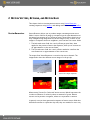
Stereoscopic images courtesy of Mr. Henry Chung, HKSC (http://www.stereoscopy.com/henry/). Images illustrating warping and morphing courtesy
of Ron Brinkmann (http://www.digitalcompositing.com). Images from “The Day After Tomorrow” ©2004 courtesy of and copyright by 20th Century
Fox. Images from "Stealth" courtesy of and copyright by Sony Pictures Inc. Images from "xXx" ©2002 courtesy of and copyright by Columbia
Pictures Industries. All rights reserved by their respective owners in the United States and/or other countries.
Thank you to Diogo Girondi for providing icons for Nuke user interface.
User Guide writing and layout design: Eija Närvänen, Tytti Pohjola, Joel Byrne, and Charles Quinn.
Proof reading: Joel Byrne, Charles Quinn, Gary Jones and Eija Närvänen
The Foundry
6th Floor
The Communications Building
Leicester Square
London
WC2H 7LT
UK
Rev: November 29, 2012
The Foundry
Nuke 7.0v1
Contents
PREFACE
About this User Guide. . . . . . . . . . . . . . . . . . . . . . . . . . . . . . . . . . . . . . . . . 19
Getting Help . . . . . . . . . . . . . . . . . . . . . . . . . . . . . . . . . . . . . . . . . . . . . . . . 19
Viewing Online Help . . . . . . . . . . . . . . . . . . . . . . . . . . . . . . . . . . . . . . 19
Contacting Customer Support. . . . . . . . . . . . . . . . . . . . . . . . . . . . . . . 20
NUKE
Organisation of the Sections . . . . . . . . . . . . . . . . . . . . . . . . . . . . . . . . . . . 21
REFORMATTING
ELEMENTS
Reformatting Images . . . . . . . . . . . . . . . . . . . . . . . . . . . . . . . . . . . . . . . . . 23
Using the Reformat Node . . . . . . . . . . . . . . . . . . . . . . . . . . . . . . . . . . 23
Cropping Elements . . . . . . . . . . . . . . . . . . . . . . . . . . . . . . . . . . . . . . . 28
Adjusting the Bounding Box . . . . . . . . . . . . . . . . . . . . . . . . . . . . . . . . . . . . 29
Resizing the Bounding Box . . . . . . . . . . . . . . . . . . . . . . . . . . . . . . . . . 29
Copying a Bounding Box from One Input to Another . . . . . . . . . . . . . 30
Adding a Black Outside Edge to the Bounding Box . . . . . . . . . . . . . . 32
CHANNELS
Quick Start . . . . . . . . . . . . . . . . . . . . . . . . . . . . . . . . . . . . . . . . . . . . . . . . . 33
Understanding Channels . . . . . . . . . . . . . . . . . . . . . . . . . . . . . . . . . . . . . . . 33
Understanding Channel Sets (Layers) . . . . . . . . . . . . . . . . . . . . . . . . . . . . . 34
Creating Channels and Channel Sets . . . . . . . . . . . . . . . . . . . . . . . . . . . . . 34
Calling Channels . . . . . . . . . . . . . . . . . . . . . . . . . . . . . . . . . . . . . . . . . . . . . 35
Viewing Channels in the Viewer . . . . . . . . . . . . . . . . . . . . . . . . . . . . . 37
Selecting Input Channels. . . . . . . . . . . . . . . . . . . . . . . . . . . . . . . . . . . 37
Selecting Masks . . . . . . . . . . . . . . . . . . . . . . . . . . . . . . . . . . . . . . . . . 38
Linking Channels Using the Link Menu . . . . . . . . . . . . . . . . . . . . . . . . . . . . 40
Tracing Channels. . . . . . . . . . . . . . . . . . . . . . . . . . . . . . . . . . . . . . . . . . . . . 40
Renaming Channels . . . . . . . . . . . . . . . . . . . . . . . . . . . . . . . . . . . . . . . . . . . 40
Removing Channels and Channel Sets . . . . . . . . . . . . . . . . . . . . . . . . . . . . 41
Swapping Channels . . . . . . . . . . . . . . . . . . . . . . . . . . . . . . . . . . . . . . . . . . . 41
Channels from Input 1 . . . . . . . . . . . . . . . . . . . . . . . . . . . . . . . . . . . . 42
Channels from Input 2 . . . . . . . . . . . . . . . . . . . . . . . . . . . . . . . . . . . . 42
Channel Outputs . . . . . . . . . . . . . . . . . . . . . . . . . . . . . . . . . . . . . . . . . 42
Assigning Constants . . . . . . . . . . . . . . . . . . . . . . . . . . . . . . . . . . . . . . 43
Creating Swap Channel Sets . . . . . . . . . . . . . . . . . . . . . . . . . . . . . . . . 43
Swapping channels . . . . . . . . . . . . . . . . . . . . . . . . . . . . . . . . . . . . . . . 44
MERGING IMAGES
Quick Start . . . . . . . . . . . . . . . . . . . . . . . . . . . . . . . . . . . . . . . . . . . . . . . . . 45
CONTENTS
Layering Images Together with the Merge Node . . . . . . . . . . . . . . . . . . . . 45
Merge Operations . . . . . . . . . . . . . . . . . . . . . . . . . . . . . . . . . . . . . . . . 47
Generating Contact Sheets . . . . . . . . . . . . . . . . . . . . . . . . . . . . . . . . . . . . . 58
Copying a Rectangle from one Image to Another. . . . . . . . . . . . . . . . . . . . 61
COLOR CORRECTION AND
COLOR SPACE
Making Tonal Adjustments . . . . . . . . . . . . . . . . . . . . . . . . . . . . . . . . . . . . . 65
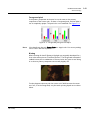
Using Histograms . . . . . . . . . . . . . . . . . . . . . . . . . . . . . . . . . . . . . . . . 65
Sampling White and Black Points . . . . . . . . . . . . . . . . . . . . . . . . . . . . 66
Making Basic Corrections . . . . . . . . . . . . . . . . . . . . . . . . . . . . . . . . . . 67
Using Sliders . . . . . . . . . . . . . . . . . . . . . . . . . . . . . . . . . . . . . . . . . . . . 68
Using Color Curves . . . . . . . . . . . . . . . . . . . . . . . . . . . . . . . . . . . . . . . 69
Making Hue, Saturation, and Value Adjustments . . . . . . . . . . . . . . . . . . . . 72
Correcting HSV . . . . . . . . . . . . . . . . . . . . . . . . . . . . . . . . . . . . . . . . . . 73
Correcting Hue . . . . . . . . . . . . . . . . . . . . . . . . . . . . . . . . . . . . . . . . . . 74
Correcting Saturation . . . . . . . . . . . . . . . . . . . . . . . . . . . . . . . . . . . . . 76
Masking Color Corrections . . . . . . . . . . . . . . . . . . . . . . . . . . . . . . . . . . . . . 77
Applying Grain. . . . . . . . . . . . . . . . . . . . . . . . . . . . . . . . . . . . . . . . . . . . . . . 78
Using Synthetic Grain . . . . . . . . . . . . . . . . . . . . . . . . . . . . . . . . . . . . . 78
Using Practical Grain . . . . . . . . . . . . . . . . . . . . . . . . . . . . . . . . . . . . . 79
Applying Mathematical Operations to Channels . . . . . . . . . . . . . . . . . . . . 82
Clamping Channel Values . . . . . . . . . . . . . . . . . . . . . . . . . . . . . . . . . . 82
Offsetting Channel Values . . . . . . . . . . . . . . . . . . . . . . . . . . . . . . . . . 83
Inverting Channel Values . . . . . . . . . . . . . . . . . . . . . . . . . . . . . . . . . . 83
Multiplying Channel Values. . . . . . . . . . . . . . . . . . . . . . . . . . . . . . . . . 84
Applying Expressions to Channel Values . . . . . . . . . . . . . . . . . . . . . . 85
Transforming the Color Space . . . . . . . . . . . . . . . . . . . . . . . . . . . . . . . . . . 86
Overriding the Default Cineon Conversion . . . . . . . . . . . . . . . . . . . . . 86
Making Other Colorspace Conversions . . . . . . . . . . . . . . . . . . . . . . . . 88
Changing the Viewer Color Space . . . . . . . . . . . . . . . . . . . . . . . . . . . . 90
KEYING WITH PRIMATTE
Connecting the Primatte Node . . . . . . . . . . . . . . . . . . . . . . . . . . . . . . . . . . 91
Primatte Basic Operation Tutorial . . . . . . . . . . . . . . . . . . . . . . . . . . . . . . . 92
Auto-Compute. . . . . . . . . . . . . . . . . . . . . . . . . . . . . . . . . . . . . . . . . . . 92
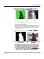
Smart Select BG Color . . . . . . . . . . . . . . . . . . . . . . . . . . . . . . . . . . . . . 93
Clean BG Noise . . . . . . . . . . . . . . . . . . . . . . . . . . . . . . . . . . . . . . . . . . 94
Clean FG Noise . . . . . . . . . . . . . . . . . . . . . . . . . . . . . . . . . . . . . . . . . . 95
Spill Removal - Method #1 . . . . . . . . . . . . . . . . . . . . . . . . . . . . . . . . . 97
Spill Removal - Method #2 . . . . . . . . . . . . . . . . . . . . . . . . . . . . . . . . . 98
Spill Removal - Method #3 . . . . . . . . . . . . . . . . . . . . . . . . . . . . . . . . . 99
Sampling Tools . . . . . . . . . . . . . . . . . . . . . . . . . . . . . . . . . . . . . . . . . . . . . . 99
The Spill Sampling Tools . . . . . . . . . . . . . . . . . . . . . . . . . . . . . . . . . . . 99
The Matte Sampling Tools . . . . . . . . . . . . . . . . . . . . . . . . . . . . . . . . 100
The Detail Sampling Tools. . . . . . . . . . . . . . . . . . . . . . . . . . . . . . . . .100
The Foundry
Nuke 7.0v1
5
CONTENTS
Replacing Spill. . . . . . . . . . . . . . . . . . . . . . . . . . . . . . . . . . . . . . . . . . . . . . 100
Primatte Controls . . . . . . . . . . . . . . . . . . . . . . . . . . . . . . . . . . . . . . . . . . . 102
Primatte Algorithms . . . . . . . . . . . . . . . . . . . . . . . . . . . . . . . . . . . . .102
Degrain Section. . . . . . . . . . . . . . . . . . . . . . . . . . . . . . . . . . . . . . . . . 107
Actions Section . . . . . . . . . . . . . . . . . . . . . . . . . . . . . . . . . . . . . . . . . 110
Adjust Lighting . . . . . . . . . . . . . . . . . . . . . . . . . . . . . . . . . . . . . . . . . 115
Hybrid Matte . . . . . . . . . . . . . . . . . . . . . . . . . . . . . . . . . . . . . . . . . . .116
Fine Tuning . . . . . . . . . . . . . . . . . . . . . . . . . . . . . . . . . . . . . . . . . . . . 117
Spill Process Section . . . . . . . . . . . . . . . . . . . . . . . . . . . . . . . . . . . . .118
Output Section . . . . . . . . . . . . . . . . . . . . . . . . . . . . . . . . . . . . . . . . . 119
The Primatte Algorithm. . . . . . . . . . . . . . . . . . . . . . . . . . . . . . . . . . . . . . . 122
Explanation of How Primatte Works. . . . . . . . . . . . . . . . . . . . . . . . .123
Explanation of How Primatte RT+ works . . . . . . . . . . . . . . . . . . . . .130
Explanation of How Primatte RT works . . . . . . . . . . . . . . . . . . . . . .131
Contact Details . . . . . . . . . . . . . . . . . . . . . . . . . . . . . . . . . . . . . . . . . . . . . 132
Main Office . . . . . . . . . . . . . . . . . . . . . . . . . . . . . . . . . . . . . . . . . . . . 132
Primatte Office . . . . . . . . . . . . . . . . . . . . . . . . . . . . . . . . . . . . . . . . .132
Proprietary Notices . . . . . . . . . . . . . . . . . . . . . . . . . . . . . . . . . . . . . . . . . 132
KEYING WITH KEYLIGHT
Quick Key . . . . . . . . . . . . . . . . . . . . . . . . . . . . . . . . . . . . . . . . . . . . . . . . . 133
Basic Keying . . . . . . . . . . . . . . . . . . . . . . . . . . . . . . . . . . . . . . . . . . . . . . . 134
Picking the Screen Color . . . . . . . . . . . . . . . . . . . . . . . . . . . . . . . . . . 134
Screen Matte. . . . . . . . . . . . . . . . . . . . . . . . . . . . . . . . . . . . . . . . . . . 135
Viewing the Key . . . . . . . . . . . . . . . . . . . . . . . . . . . . . . . . . . . . . . . . 135
Keying More . . . . . . . . . . . . . . . . . . . . . . . . . . . . . . . . . . . . . . . . . . . 136
Advanced Keying. . . . . . . . . . . . . . . . . . . . . . . . . . . . . . . . . . . . . . . . . . . . 136
Under the Hood. . . . . . . . . . . . . . . . . . . . . . . . . . . . . . . . . . . . . . . . . 137
View . . . . . . . . . . . . . . . . . . . . . . . . . . . . . . . . . . . . . . . . . . . . . . . . . 137
Screen Color . . . . . . . . . . . . . . . . . . . . . . . . . . . . . . . . . . . . . . . . . . . 139
Clip Black and White . . . . . . . . . . . . . . . . . . . . . . . . . . . . . . . . . . . . . 144
Screen Gain . . . . . . . . . . . . . . . . . . . . . . . . . . . . . . . . . . . . . . . . . . . . 145
Screen Balance . . . . . . . . . . . . . . . . . . . . . . . . . . . . . . . . . . . . . . . . . 146
PreBlur . . . . . . . . . . . . . . . . . . . . . . . . . . . . . . . . . . . . . . . . . . . . . . . 147
Tuning . . . . . . . . . . . . . . . . . . . . . . . . . . . . . . . . . . . . . . . . . . . . . . . . 147
Screen Processing. . . . . . . . . . . . . . . . . . . . . . . . . . . . . . . . . . . . . . . . . . . 147
Mattes. . . . . . . . . . . . . . . . . . . . . . . . . . . . . . . . . . . . . . . . . . . . . . . . 149
Inside and Outside Masks. . . . . . . . . . . . . . . . . . . . . . . . . . . . . . . . .150
Source Alpha . . . . . . . . . . . . . . . . . . . . . . . . . . . . . . . . . . . . . . . . . . . 151
Color Replacement . . . . . . . . . . . . . . . . . . . . . . . . . . . . . . . . . . . . . . 152
KEYING WITH ULTIMATTE
Ultimatte Quick Start . . . . . . . . . . . . . . . . . . . . . . . . . . . . . . . . . . . . . . . . 154
Connecting the Ultimatte Node . . . . . . . . . . . . . . . . . . . . . . . . . . . . . . . . 154
Sampling the Screen Color . . . . . . . . . . . . . . . . . . . . . . . . . . . . . . . . . . . . 155
The Foundry
Nuke 7.0v1
6
CONTENTS
Using Overlay Tools and Screen Correct . . . . . . . . . . . . . . . . . . . . . . . . . 156
Adjusting the Density of the Matte . . . . . . . . . . . . . . . . . . . . . . . . . . . . . 158
Adjusting Spill Controls . . . . . . . . . . . . . . . . . . . . . . . . . . . . . . . . . . . . . . 159
Retaining Shadows and Removing Noise . . . . . . . . . . . . . . . . . . . . . . . . . 160
Adjusting Color Controls. . . . . . . . . . . . . . . . . . . . . . . . . . . . . . . . . . . . . . 161
Adjusting Film Controls. . . . . . . . . . . . . . . . . . . . . . . . . . . . . . . . . . . . . . . 162
Choosing an Output Mode . . . . . . . . . . . . . . . . . . . . . . . . . . . . . . . . . . . . 162
USING ROTOPAINT
The Foundry
Roto or RotoPaint?. . . . . . . . . . . . . . . . . . . . . . . . . . . . . . . . . . . . . . . . . . 164
RotoPaint Quick Start. . . . . . . . . . . . . . . . . . . . . . . . . . . . . . . . . . . . . . . . 164
Connecting the RotoPaint Node . . . . . . . . . . . . . . . . . . . . . . . . . . . . . . . . 165
Working with the Toolbars . . . . . . . . . . . . . . . . . . . . . . . . . . . . . . . . . . . . 166
Working with the Stroke/Shape List . . . . . . . . . . . . . . . . . . . . . . . . . . . . . 166
Drawing Paint Strokes . . . . . . . . . . . . . . . . . . . . . . . . . . . . . . . . . . . . . . . 169
Using the Brush tool . . . . . . . . . . . . . . . . . . . . . . . . . . . . . . . . . . . . . 170
Using the Eraser Tool . . . . . . . . . . . . . . . . . . . . . . . . . . . . . . . . . . . .171
Using the Clone Tool. . . . . . . . . . . . . . . . . . . . . . . . . . . . . . . . . . . . .172
Using the Reveal Tool . . . . . . . . . . . . . . . . . . . . . . . . . . . . . . . . . . . .173
Using the Blur Tool . . . . . . . . . . . . . . . . . . . . . . . . . . . . . . . . . . . . . . 175
Using the Sharpen Tool. . . . . . . . . . . . . . . . . . . . . . . . . . . . . . . . . . . 175
Using the Smear Tool . . . . . . . . . . . . . . . . . . . . . . . . . . . . . . . . . . . . 176
Using the Dodge Tool . . . . . . . . . . . . . . . . . . . . . . . . . . . . . . . . . . . . . . . . 177
Using the Burn Tool . . . . . . . . . . . . . . . . . . . . . . . . . . . . . . . . . . . . .178
Drawing Shapes . . . . . . . . . . . . . . . . . . . . . . . . . . . . . . . . . . . . . . . . . . . . 178
Using the Bezier and Cusped Bezier Tools . . . . . . . . . . . . . . . . . . . .180
Using the B-Spline tool. . . . . . . . . . . . . . . . . . . . . . . . . . . . . . . . . . . 182
Using the Ellipse, Rectangle, and Cusped Rectangle Tools . . . . . . . 183
Setting Default RotoPaint Tools and Settings . . . . . . . . . . . . . . . . . . . . . 184
Selecting the Output Format and Channels . . . . . . . . . . . . . . . . . . . . . . . 187
Selecting Existing Strokes/Shapes for Editing . . . . . . . . . . . . . . . . . . . . . 188
Editing Existing Stroke/Shape Attributes . . . . . . . . . . . . . . . . . . . . . . . . . 191
Editing Attributes Common to Strokes and Shapes . . . . . . . . . . . . .191
Transforming Strokes/Shapes/Groups . . . . . . . . . . . . . . . . . . . . . . . 194
Adjusting Mask Controls. . . . . . . . . . . . . . . . . . . . . . . . . . . . . . . . . .196
Editing Shape-Specific Attributes. . . . . . . . . . . . . . . . . . . . . . . . . . .196
Editing Stroke-Specific Attributes . . . . . . . . . . . . . . . . . . . . . . . . . .198
Editing Clone or Reveal Attributes . . . . . . . . . . . . . . . . . . . . . . . . . .200
Editing Existing Stroke/Shape Timing. . . . . . . . . . . . . . . . . . . . . . . . . . . . 201
Editing Existing Stroke/Shape Stack Order . . . . . . . . . . . . . . . . . . . . . . . 202
Editing Existing Stroke/Shape Splines . . . . . . . . . . . . . . . . . . . . . . . . . . . 202
Animating Strokes/Shapes . . . . . . . . . . . . . . . . . . . . . . . . . . . . . . . . . . . . 207
Nuke 7.0v1
7
CONTENTS
Viewing Points in the Curve Editor and the Dope Sheet . . . . . . . . . . . . . 212
Copying, Pasting, and Cutting Stroke Positions . . . . . . . . . . . . . . . . . . . . 212
Copying, Pasting, and Cutting Point Positions . . . . . . . . . . . . . . . . . . . . . 214
Pasting Point Positions. . . . . . . . . . . . . . . . . . . . . . . . . . . . . . . . . . . 214
Cutting Point Positions . . . . . . . . . . . . . . . . . . . . . . . . . . . . . . . . . . .215
RotoPaint and Stereoscopic Projects . . . . . . . . . . . . . . . . . . . . . . . . . . . . 215
Selecting the View to Draw on . . . . . . . . . . . . . . . . . . . . . . . . . . . . .216
Selecting the View to Clone from . . . . . . . . . . . . . . . . . . . . . . . . . . .216
Reproducing Strokes/Shapes in Other Views . . . . . . . . . . . . . . . . . . 216
Editing Strokes/Shapes in One View Only . . . . . . . . . . . . . . . . . . . .217
Applying a Stereo Offset . . . . . . . . . . . . . . . . . . . . . . . . . . . . . . . . .218
Where Are the Bezier and Paint Nodes? . . . . . . . . . . . . . . . . . . . . . . . . . 218
TRACKING AND
STABILIZING
Quick Start . . . . . . . . . . . . . . . . . . . . . . . . . . . . . . . . . . . . . . . . . . . . . . . . 220
Connecting the Tracker Node . . . . . . . . . . . . . . . . . . . . . . . . . . . . . . . . . . 221
Adding Track Anchors. . . . . . . . . . . . . . . . . . . . . . . . . . . . . . . . . . . . . . . . 221
Positioning Track Anchors . . . . . . . . . . . . . . . . . . . . . . . . . . . . . . . .222
Tracking Preferences and Viewer Tools . . . . . . . . . . . . . . . . . . . . . . . . . . 223
Automatic vs. Keyframe Tracking . . . . . . . . . . . . . . . . . . . . . . . . . . . . . . . 224
Automatic Tracking. . . . . . . . . . . . . . . . . . . . . . . . . . . . . . . . . . . . . . . . . . 224
Calculating Auto-Tracks . . . . . . . . . . . . . . . . . . . . . . . . . . . . . . . . . .225
Troubleshooting Auto-Tracks . . . . . . . . . . . . . . . . . . . . . . . . . . . . . .226
Keyframe Tracking . . . . . . . . . . . . . . . . . . . . . . . . . . . . . . . . . . . . . . . . . . 228
Calculating Keyframe Tracks. . . . . . . . . . . . . . . . . . . . . . . . . . . . . . .229
Troubleshooting Keyframe Tracks . . . . . . . . . . . . . . . . . . . . . . . . . .230
Applying Tracking Data. . . . . . . . . . . . . . . . . . . . . . . . . . . . . . . . . . . . . . . 232
Applying Tracking Data Using Tracker’s Controls . . . . . . . . . . . . . . 232
Applying Tracking Data Using Linking Expressions . . . . . . . . . . . . . 235
Using the CornerPin2D Node . . . . . . . . . . . . . . . . . . . . . . . . . . . . . .237
TRANSFORMING
ELEMENTS
Transforming in 2D. . . . . . . . . . . . . . . . . . . . . . . . . . . . . . . . . . . . . . . . . . 240
Using the 2D Transformation Overlay . . . . . . . . . . . . . . . . . . . . . . . 240
Choosing a Filtering Algorithm . . . . . . . . . . . . . . . . . . . . . . . . . . . . . 241
How Your Nodes Concatenate . . . . . . . . . . . . . . . . . . . . . . . . . . . . . 245
Translating Elements . . . . . . . . . . . . . . . . . . . . . . . . . . . . . . . . . . . . 246
Rotating Elements. . . . . . . . . . . . . . . . . . . . . . . . . . . . . . . . . . . . . . . 248
Scaling Elements . . . . . . . . . . . . . . . . . . . . . . . . . . . . . . . . . . . . . . . . 248
Skewing Elements . . . . . . . . . . . . . . . . . . . . . . . . . . . . . . . . . . . . . . . 250
Applying Core Transformations in 2.5D . . . . . . . . . . . . . . . . . . . . . . . . . . 251
Adding a Card3D Node . . . . . . . . . . . . . . . . . . . . . . . . . . . . . . . . . . . 251
Specifying the Order of Operations . . . . . . . . . . . . . . . . . . . . . . . . . 251
Choosing a Filtering Algorithm . . . . . . . . . . . . . . . . . . . . . . . . . . . . .252
The Foundry
Nuke 7.0v1
8
CONTENTS
Using the 3D Transformation Handles . . . . . . . . . . . . . . . . . . . . . . .252
Translating Elements . . . . . . . . . . . . . . . . . . . . . . . . . . . . . . . . . . . .253
Rotating Elements. . . . . . . . . . . . . . . . . . . . . . . . . . . . . . . . . . . . . . . 253
Scaling Elements . . . . . . . . . . . . . . . . . . . . . . . . . . . . . . . . . . . . . . . . 254
Skewing Elements . . . . . . . . . . . . . . . . . . . . . . . . . . . . . . . . . . . . . . . 254
Adding Motion Blur. . . . . . . . . . . . . . . . . . . . . . . . . . . . . . . . . . . . . . . . . . 255
Replicating the Input Image Across the Output . . . . . . . . . . . . . . . . . . . . 259
WARPING AND
MORPHING IMAGES
Quick Start . . . . . . . . . . . . . . . . . . . . . . . . . . . . . . . . . . . . . . . . . . . . . . . . 261
Warping. . . . . . . . . . . . . . . . . . . . . . . . . . . . . . . . . . . . . . . . . . . . . . . . . . . 262
Warping Images Using the GridWarp Node . . . . . . . . . . . . . . . . . . .262
Warping an Image Using the SplineWarp Node . . . . . . . . . . . . . . . . 271
Morphing. . . . . . . . . . . . . . . . . . . . . . . . . . . . . . . . . . . . . . . . . . . . . . . . . . 280
Morphing One Image into Another Using the GridWarp Node . . . . . 281
Morphing One Image into Another Using the SplineWarp Node . . .283
Transforming and Animating Warps and Morphs. . . . . . . . . . . . . . . . . . . 288
Transforming Warps . . . . . . . . . . . . . . . . . . . . . . . . . . . . . . . . . . . . . 288
Animating Warps. . . . . . . . . . . . . . . . . . . . . . . . . . . . . . . . . . . . . . . .290
FILTERING AND SPATIAL
EFFECTS
Applying Convolves . . . . . . . . . . . . . . . . . . . . . . . . . . . . . . . . . . . . . . . . . . 292
Applying Blurs . . . . . . . . . . . . . . . . . . . . . . . . . . . . . . . . . . . . . . . . . . . . . . 295
Simulating Depth-of-Field Blurring. . . . . . . . . . . . . . . . . . . . . . . . . . 295
CREATING EFFECTS
Quick Start . . . . . . . . . . . . . . . . . . . . . . . . . . . . . . . . . . . . . . . . . . . . . . . . 309
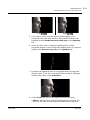
Background Reflections on Foreground Elements . . . . . . . . . . . . . . . . . . 309
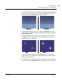
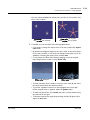
Creating Star Filter Effects on Image Highlights . . . . . . . . . . . . . . . . . . . 312
Creating Text Overlays . . . . . . . . . . . . . . . . . . . . . . . . . . . . . . . . . . . . . . . 315
Creating a Text Overlay . . . . . . . . . . . . . . . . . . . . . . . . . . . . . . . . . . 315
Repositioning and Transforming Text . . . . . . . . . . . . . . . . . . . . . . .319
Fonts . . . . . . . . . . . . . . . . . . . . . . . . . . . . . . . . . . . . . . . . . . . . . . . . . 320
Changing the Text Color . . . . . . . . . . . . . . . . . . . . . . . . . . . . . . . . . . 323
TEMPORAL OPERATIONS
Quick Start . . . . . . . . . . . . . . . . . . . . . . . . . . . . . . . . . . . . . . . . . . . . . . . . 325
Distorting Time . . . . . . . . . . . . . . . . . . . . . . . . . . . . . . . . . . . . . . . . . . . . . 326
Simple Retiming. . . . . . . . . . . . . . . . . . . . . . . . . . . . . . . . . . . . . . . . .326
Interpolation . . . . . . . . . . . . . . . . . . . . . . . . . . . . . . . . . . . . . . . . . . . 327
Frame-blending . . . . . . . . . . . . . . . . . . . . . . . . . . . . . . . . . . . . . . . . .328
OFlow Retiming . . . . . . . . . . . . . . . . . . . . . . . . . . . . . . . . . . . . . . . . . 329
OFlow Parameters. . . . . . . . . . . . . . . . . . . . . . . . . . . . . . . . . . . . . . . 330
Warping Clips . . . . . . . . . . . . . . . . . . . . . . . . . . . . . . . . . . . . . . . . . . 333
Global Frame Range and Speed. . . . . . . . . . . . . . . . . . . . . . . . . . . . . 335
Applying the TimeBlur Filter . . . . . . . . . . . . . . . . . . . . . . . . . . . . . . . . . . . 336
The Foundry
Nuke 7.0v1
9
CONTENTS
Editing Clips . . . . . . . . . . . . . . . . . . . . . . . . . . . . . . . . . . . . . . . . . . . . . . . 336
Slipping Clips. . . . . . . . . . . . . . . . . . . . . . . . . . . . . . . . . . . . . . . . . . . 336
Cutting Clips . . . . . . . . . . . . . . . . . . . . . . . . . . . . . . . . . . . . . . . . . . .339
Splicing Clips . . . . . . . . . . . . . . . . . . . . . . . . . . . . . . . . . . . . . . . . . . . 340
Freeze Framing Clips . . . . . . . . . . . . . . . . . . . . . . . . . . . . . . . . . . . . . 341
ANALYZING FRAME
SEQUENCES
Quick Start . . . . . . . . . . . . . . . . . . . . . . . . . . . . . . . . . . . . . . . . . . . . . . . . 343
Analysing and Matching Frame Sequences . . . . . . . . . . . . . . . . . . . . . . . . 343
Cropping Black Edges . . . . . . . . . . . . . . . . . . . . . . . . . . . . . . . . . . . . 344
Analyzing the Intensity of a Frame Sequence. . . . . . . . . . . . . . . . . . 345
Removing Flicker . . . . . . . . . . . . . . . . . . . . . . . . . . . . . . . . . . . . . . . . 346
To Analyze the Exposure Differences . . . . . . . . . . . . . . . . . . . . . . . . 347
Tracking the Brightest and Darkest Pixels . . . . . . . . . . . . . . . . . . . . 347
AUDIO IN NUKE
Quick Start . . . . . . . . . . . . . . . . . . . . . . . . . . . . . . . . . . . . . . . . . . . . . . . . 349
Creating an AudioRead . . . . . . . . . . . . . . . . . . . . . . . . . . . . . . . . . . . 349
Adjusting AudioRead controls . . . . . . . . . . . . . . . . . . . . . . . . . . . . .350
Creating a Keyframe Curve . . . . . . . . . . . . . . . . . . . . . . . . . . . . . . . . 350
Modifying the Audio curve in the Curve Editor and Dope Sheet . . .351
Flipbooking the Audio Track . . . . . . . . . . . . . . . . . . . . . . . . . . . . . . .351
3D COMPOSITING
Overview . . . . . . . . . . . . . . . . . . . . . . . . . . . . . . . . . . . . . . . . . . . . . . . . . . 353
Setting Up a Scene . . . . . . . . . . . . . . . . . . . . . . . . . . . . . . . . . . . . . . . . . . 354
The Scene Node . . . . . . . . . . . . . . . . . . . . . . . . . . . . . . . . . . . . . . . . 354
The ScanlineRender Node . . . . . . . . . . . . . . . . . . . . . . . . . . . . . . . . . 354
The Camera Node . . . . . . . . . . . . . . . . . . . . . . . . . . . . . . . . . . . . . . . 355
Using the 3D Viewer. . . . . . . . . . . . . . . . . . . . . . . . . . . . . . . . . . . . . . . . . 356
3D Scene Geometry. . . . . . . . . . . . . . . . . . . . . . . . . . . . . . . . . . . . . . . . . . 359
Working with Cards. . . . . . . . . . . . . . . . . . . . . . . . . . . . . . . . . . . . . .360
Working with Cubes . . . . . . . . . . . . . . . . . . . . . . . . . . . . . . . . . . . . . 363
Working with Spheres . . . . . . . . . . . . . . . . . . . . . . . . . . . . . . . . . . . . 364
Creating a Position Pass Using the DepthToPosition Node . . . . . . . 365
Creating a Dense Point Cloud Using the PositionToPoints Node. . . 367
Creating a Point Cloud Using the DepthToPoints Node . . . . . . . . . . 368
3D Selection Tools . . . . . . . . . . . . . . . . . . . . . . . . . . . . . . . . . . . . . . . . . . 369
Matching Position, Orientation and Size to 3D Selection . . . . . . . . 372
Parenting to Axis Objects . . . . . . . . . . . . . . . . . . . . . . . . . . . . . . . . . 372
Merging Objects . . . . . . . . . . . . . . . . . . . . . . . . . . . . . . . . . . . . . . . . . . . . 373
Object Material Properties . . . . . . . . . . . . . . . . . . . . . . . . . . . . . . . . . . . . 374
Projecting Textures onto Objects. . . . . . . . . . . . . . . . . . . . . . . . . . . . . . . 378
Projecting Textures with the UVProject Node . . . . . . . . . . . . . . . . . 378
Projecting Textures with the Project3D Node . . . . . . . . . . . . . . . . . 379
Importing UDIM Patches. . . . . . . . . . . . . . . . . . . . . . . . . . . . . . . . . . . . . . 380
The Foundry
Nuke 7.0v1
10
CONTENTS
Replacing Material Channels with a Constant Color. . . . . . . . . . . . . . . . . 383
Merging Shaders . . . . . . . . . . . . . . . . . . . . . . . . . . . . . . . . . . . . . . . . . . . . 384
Merging Two Shader Nodes . . . . . . . . . . . . . . . . . . . . . . . . . . . . . . . 384
Merging a Material with the Objects Behind . . . . . . . . . . . . . . . . . .385
Object Display Properties . . . . . . . . . . . . . . . . . . . . . . . . . . . . . . . . . . . . . 389
Transforming Objects . . . . . . . . . . . . . . . . . . . . . . . . . . . . . . . . . . . . . . . . 391
Using the Transform Handles . . . . . . . . . . . . . . . . . . . . . . . . . . . . . . 391
Transforming from the Node Properties Panel. . . . . . . . . . . . . . . . . 393
Transformations and the Pivot Point . . . . . . . . . . . . . . . . . . . . . . . . 394
Using the TransformGeo Node . . . . . . . . . . . . . . . . . . . . . . . . . . . . . 394
Modifying Object Shapes . . . . . . . . . . . . . . . . . . . . . . . . . . . . . . . . . . . . . 397
Modifying Objects Using Lookup Curves . . . . . . . . . . . . . . . . . . . . .397
Modifying Objects Using a Power Function . . . . . . . . . . . . . . . . . . .399
Modifying Objects Using an Image . . . . . . . . . . . . . . . . . . . . . . . . . . 400
Modifying Objects Using a Perlin Noise Function. . . . . . . . . . . . . . . 404
Modifying Objects Using a Distortion Function . . . . . . . . . . . . . . . . 405
Modifying Objects Using a Trilinear Interpolation . . . . . . . . . . . . . . 406
Lighting . . . . . . . . . . . . . . . . . . . . . . . . . . . . . . . . . . . . . . . . . . . . . . . . . . . 406
Direct Light . . . . . . . . . . . . . . . . . . . . . . . . . . . . . . . . . . . . . . . . . . . . 407
Point Light. . . . . . . . . . . . . . . . . . . . . . . . . . . . . . . . . . . . . . . . . . . . . 408
Spot Light . . . . . . . . . . . . . . . . . . . . . . . . . . . . . . . . . . . . . . . . . . . . . 408
Environment Light . . . . . . . . . . . . . . . . . . . . . . . . . . . . . . . . . . . . . . . 409
The Light Node . . . . . . . . . . . . . . . . . . . . . . . . . . . . . . . . . . . . . . . . . 411
Casting Shadows . . . . . . . . . . . . . . . . . . . . . . . . . . . . . . . . . . . . . . . . 412
Relighting a 2D Image Using 3D Lights . . . . . . . . . . . . . . . . . . . . . . 419
Manipulating Object Normals . . . . . . . . . . . . . . . . . . . . . . . . . . . . . . . . . . 421
Working with Cameras . . . . . . . . . . . . . . . . . . . . . . . . . . . . . . . . . . . . . . . 422
Projection Cameras . . . . . . . . . . . . . . . . . . . . . . . . . . . . . . . . . . . . . . . . . . 424
First a Little Math... . . . . . . . . . . . . . . . . . . . . . . . . . . . . . . . . . . . . . 424
Setting Up the Projection Camera Script . . . . . . . . . . . . . . . . . . . . . 425
Adding Motion Blur to the 3D Scene . . . . . . . . . . . . . . . . . . . . . . . . . . . . 427
Adding Motion Blur Using ScanlineRender . . . . . . . . . . . . . . . . . . . . 427
Adding Motion Blur Using VectorBlur. . . . . . . . . . . . . . . . . . . . . . . . 430
Importing Files or Objects from Other Applications. . . . . . . . . . . . . . . . . 434
Working with OBJ Objects. . . . . . . . . . . . . . . . . . . . . . . . . . . . . . . . . 435
Working with Alembic Files . . . . . . . . . . . . . . . . . . . . . . . . . . . . . . . . 436
Working with FBX Files . . . . . . . . . . . . . . . . . . . . . . . . . . . . . . . . . . . 438
Importing Cameras from Boujou . . . . . . . . . . . . . . . . . . . . . . . . . . . . 444
Applying Tracks to an Object . . . . . . . . . . . . . . . . . . . . . . . . . . . . . . 445
Exporting Geometry, Cameras, Lights, Axes, or Point Clouds . . . . . . . . . 446
Rendering a 3D Scene. . . . . . . . . . . . . . . . . . . . . . . . . . . . . . . . . . . . . . . . 447
Adjusting the Render Parameters . . . . . . . . . . . . . . . . . . . . . . . . . . . 447
The Foundry
Nuke 7.0v1
11
CONTENTS
DEEP COMPOSITING
Introduction . . . . . . . . . . . . . . . . . . . . . . . . . . . . . . . . . . . . . . . . . . . . . . . 451
Quick Start . . . . . . . . . . . . . . . . . . . . . . . . . . . . . . . . . . . . . . . . . . . . . . . . 452
Reading in Deep Footage . . . . . . . . . . . . . . . . . . . . . . . . . . . . . . . . . . . . . 452
Importing DTEX Files . . . . . . . . . . . . . . . . . . . . . . . . . . . . . . . . . . . . 452
Importing Scanline OpenEXR 2.0 Files . . . . . . . . . . . . . . . . . . . . . . . 453
Viewing Depth Information in the Deep Graph. . . . . . . . . . . . . . . . . . . . . 453
Merging Deep Images . . . . . . . . . . . . . . . . . . . . . . . . . . . . . . . . . . . . . . . . 454
Creating Holdouts. . . . . . . . . . . . . . . . . . . . . . . . . . . . . . . . . . . . . . . . . . . 455
Creating 2D and 3D Elements from Deep Images . . . . . . . . . . . . . . . . . . 456
Modifying Deep Data . . . . . . . . . . . . . . . . . . . . . . . . . . . . . . . . . . . . . . . . 457
Cropping, Reformatting and Transforming Deep Images . . . . . . . . . . . . . 459
Sampling Deep Images . . . . . . . . . . . . . . . . . . . . . . . . . . . . . . . . . . . . . . . 461
Creating Deep Data. . . . . . . . . . . . . . . . . . . . . . . . . . . . . . . . . . . . . . . . . . 461
Writing Deep Data . . . . . . . . . . . . . . . . . . . . . . . . . . . . . . . . . . . . . . . . . . 463
WORKING WITH
STEREOSCOPIC PROJECTS
Quick Start . . . . . . . . . . . . . . . . . . . . . . . . . . . . . . . . . . . . . . . . . . . . . . . . 465
Setting Up Views for the Script . . . . . . . . . . . . . . . . . . . . . . . . . . . . . . . . 466
Loading Multi-View Images . . . . . . . . . . . . . . . . . . . . . . . . . . . . . . . . . . . 468
Displaying Views in the Viewer . . . . . . . . . . . . . . . . . . . . . . . . . . . . . . . . 470
Selecting Which Views to Apply Changes To . . . . . . . . . . . . . . . . . . . . . . 472
Splitting Views Off . . . . . . . . . . . . . . . . . . . . . . . . . . . . . . . . . . . . . . 473
Selecting the View to Process When Using the RotoPaint Node . . . 475
Performing Different Actions on Different Views . . . . . . . . . . . . . . . . . . 475
Reproducing Changes Made to One View. . . . . . . . . . . . . . . . . . . . . . . . . 476
Reproducing X and Y Values. . . . . . . . . . . . . . . . . . . . . . . . . . . . . . . 477
Swapping Views . . . . . . . . . . . . . . . . . . . . . . . . . . . . . . . . . . . . . . . . . . . . 478
Converting Images into Anaglyph . . . . . . . . . . . . . . . . . . . . . . . . . . . . . . . 478
Changing Convergence . . . . . . . . . . . . . . . . . . . . . . . . . . . . . . . . . . . . . . . 480
Previewing and Rendering Stereoscopic Images . . . . . . . . . . . . . . . . . . . 485
Flipbooking Stereo Images within FrameCycler . . . . . . . . . . . . . . . . 485
Rendering Stereoscopic Images . . . . . . . . . . . . . . . . . . . . . . . . . . . . 485
PREVIEWS AND
RENDERING
Quick Start . . . . . . . . . . . . . . . . . . . . . . . . . . . . . . . . . . . . . . . . . . . . . . . . 487
Previewing Output . . . . . . . . . . . . . . . . . . . . . . . . . . . . . . . . . . . . . . . . . . 488
Previewing in a Nuke Viewer . . . . . . . . . . . . . . . . . . . . . . . . . . . . . . 488
Flipbooking Sequences . . . . . . . . . . . . . . . . . . . . . . . . . . . . . . . . . . . 488
Previewing on an External Broadcast Video Monitor. . . . . . . . . . . . 491
Rendering Output . . . . . . . . . . . . . . . . . . . . . . . . . . . . . . . . . . . . . . . . . . . 493
Render Resolution and Format . . . . . . . . . . . . . . . . . . . . . . . . . . . . . 493
Output (Write) Nodes . . . . . . . . . . . . . . . . . . . . . . . . . . . . . . . . . . . . 494
File Name Conventions for Rendered Images . . . . . . . . . . . . . . . . . . 498
The Foundry
Nuke 7.0v1
12
CONTENTS
Changing the Numbering of Rendered Frames . . . . . . . . . . . . . . . . . 499
Using a Write Node to Read in the Rendered Image . . . . . . . . . . . .501
Render Farms . . . . . . . . . . . . . . . . . . . . . . . . . . . . . . . . . . . . . . . . . . 502
EXPRESSIONS
Quick Start . . . . . . . . . . . . . . . . . . . . . . . . . . . . . . . . . . . . . . . . . . . . . . . . 503
Understanding Expression Syntax . . . . . . . . . . . . . . . . . . . . . . . . . . . . . . 503
Linking Expressions. . . . . . . . . . . . . . . . . . . . . . . . . . . . . . . . . . . . . . 503
Linking Channels and Formats Using Expressions . . . . . . . . . . . . . . . . . . 507
To Convert Expressions Between Scripting Languages . . . . . . . . . .507
Adding Mathematical Functions to Expressions. . . . . . . . . . . . . . . . . . . . 508
THE SCRIPT EDITOR AND
PYTHON
Quick Start . . . . . . . . . . . . . . . . . . . . . . . . . . . . . . . . . . . . . . . . . . . . . . . . 514
Using the Script Editor . . . . . . . . . . . . . . . . . . . . . . . . . . . . . . . . . . . . . . . 514
Automating Procedures . . . . . . . . . . . . . . . . . . . . . . . . . . . . . . . . . . . . . . 518
Getting Help . . . . . . . . . . . . . . . . . . . . . . . . . . . . . . . . . . . . . . . . . . . . . . . 519
More Documentation . . . . . . . . . . . . . . . . . . . . . . . . . . . . . . . . . . . . 519
Viewing More Examples . . . . . . . . . . . . . . . . . . . . . . . . . . . . . . . . . . 519
Using the Help Statement. . . . . . . . . . . . . . . . . . . . . . . . . . . . . . . . . 520
Python on the Web . . . . . . . . . . . . . . . . . . . . . . . . . . . . . . . . . . . . . . 520
SETTING INTERFACE
PREFERENCES
Displaying the Preferences Dialog . . . . . . . . . . . . . . . . . . . . . . . . . . . . . . 521
Changing Preferences . . . . . . . . . . . . . . . . . . . . . . . . . . . . . . . . . . . . . . . . 521
Saving Preferences . . . . . . . . . . . . . . . . . . . . . . . . . . . . . . . . . . . . . . . . . . 522
Resetting Preferences. . . . . . . . . . . . . . . . . . . . . . . . . . . . . . . . . . . . . . . . 522
The Available Preference Settings . . . . . . . . . . . . . . . . . . . . . . . . . . . . . . 522
Preferences Tab . . . . . . . . . . . . . . . . . . . . . . . . . . . . . . . . . . . . . . . . 523
Windows Tab. . . . . . . . . . . . . . . . . . . . . . . . . . . . . . . . . . . . . . . . . . . 526
Control Panels Tab . . . . . . . . . . . . . . . . . . . . . . . . . . . . . . . . . . . . . .527
Appearance Tab . . . . . . . . . . . . . . . . . . . . . . . . . . . . . . . . . . . . . . . . 529
Node Colors Tab . . . . . . . . . . . . . . . . . . . . . . . . . . . . . . . . . . . . . . . . 531
Node Graph Tab . . . . . . . . . . . . . . . . . . . . . . . . . . . . . . . . . . . . . . . . 532
Viewers Tab . . . . . . . . . . . . . . . . . . . . . . . . . . . . . . . . . . . . . . . . . . . 536
Script Editor Tab . . . . . . . . . . . . . . . . . . . . . . . . . . . . . . . . . . . . . . . . 541
CONFIGURING NUKE
What Is a Terminal and How Do I Use One?. . . . . . . . . . . . . . . . . . . . . . . 542
Command Line Operations . . . . . . . . . . . . . . . . . . . . . . . . . . . . . . . . . . . . 543
Environment Variables . . . . . . . . . . . . . . . . . . . . . . . . . . . . . . . . . . . . . . . 551
Setting Environment Variables . . . . . . . . . . . . . . . . . . . . . . . . . . . . . 551
Nuke Environment Variables. . . . . . . . . . . . . . . . . . . . . . . . . . . . . . .555
Loading Gizmos, NDK Plug-ins, and TCL scripts. . . . . . . . . . . . . . . . . . . . 556
Defining the Nuke Plug-in Path . . . . . . . . . . . . . . . . . . . . . . . . . . . . 557
Loading Python Scripts . . . . . . . . . . . . . . . . . . . . . . . . . . . . . . . . . . . . . . . 558
The Foundry
Nuke 7.0v1
13
CONTENTS
Loading OFX Plug-ins . . . . . . . . . . . . . . . . . . . . . . . . . . . . . . . . . . . . . . . . 558
Defining Common Favorite Directories . . . . . . . . . . . . . . . . . . . . . . . . . . . 559
Handling File Paths Cross Platform . . . . . . . . . . . . . . . . . . . . . . . . . . . . . 561
Setting Default Values for Controls . . . . . . . . . . . . . . . . . . . . . . . . . . . . . 562
Defining Custom Menus and Toolbars . . . . . . . . . . . . . . . . . . . . . . . . . . . 562
Defining Common Image Formats . . . . . . . . . . . . . . . . . . . . . . . . . . . . . . . 569
Gizmos, Custom Plug-ins, and Generic TCL Scripts . . . . . . . . . . . . . . . . . 569
Creating and Sourcing Gizmos . . . . . . . . . . . . . . . . . . . . . . . . . . . . . 570
Custom Plug-ins . . . . . . . . . . . . . . . . . . . . . . . . . . . . . . . . . . . . . . . . 582
Sourcing TCL Procedure . . . . . . . . . . . . . . . . . . . . . . . . . . . . . . . . . . 582
Template Scripts . . . . . . . . . . . . . . . . . . . . . . . . . . . . . . . . . . . . . . . . . . . . 583
Defining Common Preferences . . . . . . . . . . . . . . . . . . . . . . . . . . . . . . . . . 584
Altering a Script’s Lookup Tables (LUTs) . . . . . . . . . . . . . . . . . . . . . . . . . 585
Displaying, Adding, Editing, and Deleting LUTs . . . . . . . . . . . . . . . .586
Selecting the LUT to Use . . . . . . . . . . . . . . . . . . . . . . . . . . . . . . . . . 588
Default LUT settings . . . . . . . . . . . . . . . . . . . . . . . . . . . . . . . . . . . . . 589
Example Cases . . . . . . . . . . . . . . . . . . . . . . . . . . . . . . . . . . . . . . . . . 589
Using OCIO Config Files . . . . . . . . . . . . . . . . . . . . . . . . . . . . . . . . . .590
Creating Custom Viewer Processes . . . . . . . . . . . . . . . . . . . . . . . . . . . . . 591
Using a Gizmo as a Custom Viewer Process. . . . . . . . . . . . . . . . . . .592
Applying Custom Viewer Processes to Images . . . . . . . . . . . . . . . . . 596
NUKEX
NukeX Features . . . . . . . . . . . . . . . . . . . . . . . . . . . . . . . . . . . . . . . . . . . . 597
Installing NukeX . . . . . . . . . . . . . . . . . . . . . . . . . . . . . . . . . . . . . . . . . . . . 598
Licensing NukeX . . . . . . . . . . . . . . . . . . . . . . . . . . . . . . . . . . . . . . . . . . . . 599
Launching NukeX . . . . . . . . . . . . . . . . . . . . . . . . . . . . . . . . . . . . . . . . . . . 599
On Windows . . . . . . . . . . . . . . . . . . . . . . . . . . . . . . . . . . . . . . . . . . . 599
On Linux . . . . . . . . . . . . . . . . . . . . . . . . . . . . . . . . . . . . . . . . . . . . . . 599
On Mac OS X. . . . . . . . . . . . . . . . . . . . . . . . . . . . . . . . . . . . . . . . . . . 599
REMOVING NOISE WITH
DENOISE
Quick Start . . . . . . . . . . . . . . . . . . . . . . . . . . . . . . . . . . . . . . . . . . . . . . . . 600
Connecting Denoise . . . . . . . . . . . . . . . . . . . . . . . . . . . . . . . . . . . . . . . . . 601
Analysing and Removing Noise. . . . . . . . . . . . . . . . . . . . . . . . . . . . . . . . . 601
Reviewing the Results. . . . . . . . . . . . . . . . . . . . . . . . . . . . . . . . . . . . . . . . 603
Fine Tuning . . . . . . . . . . . . . . . . . . . . . . . . . . . . . . . . . . . . . . . . . . . . . . . . 604
MOTION VECTORS,
RETIMING, AND MOTION
BLUR
VectorGenerator . . . . . . . . . . . . . . . . . . . . . . . . . . . . . . . . . . . . . . . . . . . . 607
Quick Start . . . . . . . . . . . . . . . . . . . . . . . . . . . . . . . . . . . . . . . . . . . . . . . . 608
Connecting VectorGenerator . . . . . . . . . . . . . . . . . . . . . . . . . . . . . . . . . . 608
The Foundry
Nuke 7.0v1
14
CONTENTS
Viewing and Refining the Results . . . . . . . . . . . . . . . . . . . . . . . . . . . . . . . 609
Kronos. . . . . . . . . . . . . . . . . . . . . . . . . . . . . . . . . . . . . . . . . . . . . . . . . . . . 610
Quick Start . . . . . . . . . . . . . . . . . . . . . . . . . . . . . . . . . . . . . . . . . . . . 611
Connecting Kronos . . . . . . . . . . . . . . . . . . . . . . . . . . . . . . . . . . . . . . 611
Retiming the Sequence . . . . . . . . . . . . . . . . . . . . . . . . . . . . . . . . . . . 612
Adding Motion Blur . . . . . . . . . . . . . . . . . . . . . . . . . . . . . . . . . . . . . .613
Refining the Results . . . . . . . . . . . . . . . . . . . . . . . . . . . . . . . . . . . . . 614
MotionBlur . . . . . . . . . . . . . . . . . . . . . . . . . . . . . . . . . . . . . . . . . . . . . . . . 617
Quick Start . . . . . . . . . . . . . . . . . . . . . . . . . . . . . . . . . . . . . . . . . . . . 617
Connecting MotionBlur . . . . . . . . . . . . . . . . . . . . . . . . . . . . . . . . . . .618
Adjusting MotionBlur Controls . . . . . . . . . . . . . . . . . . . . . . . . . . . . .618
ADDING AND REMOVING
LENS DISTORTION
Quick Start . . . . . . . . . . . . . . . . . . . . . . . . . . . . . . . . . . . . . . . . . . . . . . . . 620
Calculating Lens Distortion Automatically . . . . . . . . . . . . . . . . . . . . . . . . 621
Image Analysis Parameters. . . . . . . . . . . . . . . . . . . . . . . . . . . . . . . . 621
Analyzing Distortion Using a Grid . . . . . . . . . . . . . . . . . . . . . . . . . . . . . . 622
Grid Analysis Parameters . . . . . . . . . . . . . . . . . . . . . . . . . . . . . . . . . 622
Analyzing Distortion Using Lines . . . . . . . . . . . . . . . . . . . . . . . . . . . . . . . 622
Line Analysis Parameters . . . . . . . . . . . . . . . . . . . . . . . . . . . . . . . . .623
Adjusting LensDistortion Parameters. . . . . . . . . . . . . . . . . . . . . . . . . . . . 623
Calculating the Distortion on One Image and Applying it to Another . . . 625
Applying Lens Distortion to a Card Node . . . . . . . . . . . . . . . . . . . . . . . . . 625
TRACKING WITH
PLANARTRACKER
Quick Start . . . . . . . . . . . . . . . . . . . . . . . . . . . . . . . . . . . . . . . . . . . . . . . . 627
Connecting the PlanarTracker Node . . . . . . . . . . . . . . . . . . . . . . . . . . . . . 628
Tracking a Plane . . . . . . . . . . . . . . . . . . . . . . . . . . . . . . . . . . . . . . . . . . . . 628
Reusing a Track Result . . . . . . . . . . . . . . . . . . . . . . . . . . . . . . . . . . .631
Placing an Image on the Planar Surface . . . . . . . . . . . . . . . . . . . . . .632
Adjusting Tracking Results . . . . . . . . . . . . . . . . . . . . . . . . . . . . . . . .635
CAMERA TRACKING
Quick Start . . . . . . . . . . . . . . . . . . . . . . . . . . . . . . . . . . . . . . . . . . . . . . . . 637
Connecting the CameraTracker Node . . . . . . . . . . . . . . . . . . . . . . . . . . . . 638
Tracking Features in a Sequence . . . . . . . . . . . . . . . . . . . . . . . . . . . . . . . 638
Seeding Tracks . . . . . . . . . . . . . . . . . . . . . . . . . . . . . . . . . . . . . . . . .638
Setting Tracking Parameters. . . . . . . . . . . . . . . . . . . . . . . . . . . . . . . 638
Masking Out Regions of the Image. . . . . . . . . . . . . . . . . . . . . . . . . . 640
Creating Manual Tracks . . . . . . . . . . . . . . . . . . . . . . . . . . . . . . . . . . 641
Setting the Camera Parameters . . . . . . . . . . . . . . . . . . . . . . . . . . . . . . . . 642
Adjusting the Camera Parameters . . . . . . . . . . . . . . . . . . . . . . . . . . 642
Accounting for Lens Distortion. . . . . . . . . . . . . . . . . . . . . . . . . . . . . . . . . 643
Solving the Camera Position . . . . . . . . . . . . . . . . . . . . . . . . . . . . . . . . . . . 644
Clearing Automatic Tracks . . . . . . . . . . . . . . . . . . . . . . . . . . . . . . . . 646
The Foundry
Nuke 7.0v1
15
CONTENTS
Adjusting the Solve . . . . . . . . . . . . . . . . . . . . . . . . . . . . . . . . . . . . . . . . . . 646
Viewing Tracks and Track Information . . . . . . . . . . . . . . . . . . . . . . . 646
Deleting Tracks . . . . . . . . . . . . . . . . . . . . . . . . . . . . . . . . . . . . . . . . . 647
Refining the Solve . . . . . . . . . . . . . . . . . . . . . . . . . . . . . . . . . . . . . . . 648
Transforming the Scene . . . . . . . . . . . . . . . . . . . . . . . . . . . . . . . . . . . . . . 651
Adjusting the Virtual Camera . . . . . . . . . . . . . . . . . . . . . . . . . . . . . . . . . . 651
Centering on Selected Tracks . . . . . . . . . . . . . . . . . . . . . . . . . . . . . . . . . . 652
Troubleshooting the Solve . . . . . . . . . . . . . . . . . . . . . . . . . . . . . . . . . . . . 652
Using the Point Cloud . . . . . . . . . . . . . . . . . . . . . . . . . . . . . . . . . . . . . . . . 652
Setting Points on Ground Origin or Different Axes . . . . . . . . . . . . . 653
Setting a Ground Plane . . . . . . . . . . . . . . . . . . . . . . . . . . . . . . . . . . . 653
Scaling a Scene . . . . . . . . . . . . . . . . . . . . . . . . . . . . . . . . . . . . . . . . . 654
Attaching Objects to the Footage . . . . . . . . . . . . . . . . . . . . . . . . . . 654
Copying Translate and Rotate Values . . . . . . . . . . . . . . . . . . . . . . . 655
Exporting a Point Cloud . . . . . . . . . . . . . . . . . . . . . . . . . . . . . . . . . . . . . . 655
Tracking Multiview Projects . . . . . . . . . . . . . . . . . . . . . . . . . . . . . . . . . . . 655
GENERATING DEPTH
MAPS
Quick Start . . . . . . . . . . . . . . . . . . . . . . . . . . . . . . . . . . . . . . . . . . . . . . . . 657
Connecting DepthGenerator . . . . . . . . . . . . . . . . . . . . . . . . . . . . . . . . . . . 658
Selecting What to Output . . . . . . . . . . . . . . . . . . . . . . . . . . . . . . . . . . . . . 659
Analyzing the Depth . . . . . . . . . . . . . . . . . . . . . . . . . . . . . . . . . . . . . . . . . 661
Refining the Results . . . . . . . . . . . . . . . . . . . . . . . . . . . . . . . . . . . . . . . . . 662
Using the Results . . . . . . . . . . . . . . . . . . . . . . . . . . . . . . . . . . . . . . . . . . . 665
CREATING DENSE POINT
CLOUDS AND 3D
MESHES
Quick Start . . . . . . . . . . . . . . . . . . . . . . . . . . . . . . . . . . . . . . . . . . . . . . . . 667
Connecting the PointCloud-Generator Node . . . . . . . . . . . . . . . . . . . . . . 668
Masking Out Regions of the Image. . . . . . . . . . . . . . . . . . . . . . . . . .668
Setting Keyframes in a Sequence . . . . . . . . . . . . . . . . . . . . . . . . . . . . . . . 669
Tracking a Dense Point Cloud. . . . . . . . . . . . . . . . . . . . . . . . . . . . . . . . . . 669
Filtering Your Point Cloud. . . . . . . . . . . . . . . . . . . . . . . . . . . . . . . . . . . . . 671
Removing Rejected Points. . . . . . . . . . . . . . . . . . . . . . . . . . . . . . . . .672
Grouping, Labeling, and Baking Points . . . . . . . . . . . . . . . . . . . . . . . . . . . 673
Creating a Mesh from a Point Cloud. . . . . . . . . . . . . . . . . . . . . . . . . . . . . 674
Adding Texture to a Mesh . . . . . . . . . . . . . . . . . . . . . . . . . . . . . . . . 675
Using the PoissonMesh Node . . . . . . . . . . . . . . . . . . . . . . . . . . . . . . . . . . 675
Adding Texture To The PoissonMesh . . . . . . . . . . . . . . . . . . . . . . . .676
CREATING 3D MODELS
FOR 2D SHOTS
Quick Start . . . . . . . . . . . . . . . . . . . . . . . . . . . . . . . . . . . . . . . . . . . . . . . . 679
Connecting the ModelBuilder Node . . . . . . . . . . . . . . . . . . . . . . . . . . . . . 679
Creating Shapes . . . . . . . . . . . . . . . . . . . . . . . . . . . . . . . . . . . . . . . . . . . . 680
Editing Shapes’ Display Characteristics . . . . . . . . . . . . . . . . . . . . . . . . . . 682
The Foundry
Nuke 7.0v1
16
CONTENTS
Positioning Shapes . . . . . . . . . . . . . . . . . . . . . . . . . . . . . . . . . . . . . . . . . . 684
Editing Shapes . . . . . . . . . . . . . . . . . . . . . . . . . . . . . . . . . . . . . . . . . . . . . 686
Editing Vertices. . . . . . . . . . . . . . . . . . . . . . . . . . . . . . . . . . . . . . . . . 687
Editing Edges . . . . . . . . . . . . . . . . . . . . . . . . . . . . . . . . . . . . . . . . . . 689
Editing Faces. . . . . . . . . . . . . . . . . . . . . . . . . . . . . . . . . . . . . . . . . . . 692
Editing Objects . . . . . . . . . . . . . . . . . . . . . . . . . . . . . . . . . . . . . . . . . 694
Using the Results . . . . . . . . . . . . . . . . . . . . . . . . . . . . . . . . . . . . . . . . . . . 695
Baking out the Selected Shapes . . . . . . . . . . . . . . . . . . . . . . . . . . . . 695
Projecting Textures on the Shapes. . . . . . . . . . . . . . . . . . . . . . . . . .696
USING
PROJECTIONSOLVER
Quick Start . . . . . . . . . . . . . . . . . . . . . . . . . . . . . . . . . . . . . . . . . . . . . . . . 698
Connecting the ProjectionSolver Node . . . . . . . . . . . . . . . . . . . . . . . . . . . 698
Matching 3D Geometry with 2D Footage . . . . . . . . . . . . . . . . . . . . . . . . . 699
Copying Values From a Tracker Node. . . . . . . . . . . . . . . . . . . . . . . . 699
Solving Your Camera . . . . . . . . . . . . . . . . . . . . . . . . . . . . . . . . . . . . . 700
Adjusting Solver and Lens Controls . . . . . . . . . . . . . . . . . . . . . . . . .700
Refining the Solve . . . . . . . . . . . . . . . . . . . . . . . . . . . . . . . . . . . . . . . . . . . 701
Creating Cards . . . . . . . . . . . . . . . . . . . . . . . . . . . . . . . . . . . . . . . . . . . . . 702
CREATING 3D PARTICLES
Quick Start . . . . . . . . . . . . . . . . . . . . . . . . . . . . . . . . . . . . . . . . . . . . . . . . 703
Connecting Particle Nodes . . . . . . . . . . . . . . . . . . . . . . . . . . . . . . . . . . . . 703
Creating Particles . . . . . . . . . . . . . . . . . . . . . . . . . . . . . . . . . . . . . . . . . . . 704
Emitting and Spawning Particles . . . . . . . . . . . . . . . . . . . . . . . . . . .705
Adjusting the Speed and Direction of the Particles . . . . . . . . . . . . .711
Modifying the Particles’ Movement . . . . . . . . . . . . . . . . . . . . . . . . . 713
Adjusting Controls Common to Several Particle Nodes . . . . . . . . . .716
Customising the Particle Stream. . . . . . . . . . . . . . . . . . . . . . . . . . . .718
Particle Expression Functions. . . . . . . . . . . . . . . . . . . . . . . . . . . . . . . . . . 721
RENDERING WITH
PRMANRENDER
Setting Up RenderMan Pro Server and PrmanRender . . . . . . . . . . . . . . . 724
Using The PrmanRender Node . . . . . . . . . . . . . . . . . . . . . . . . . . . . . . . . . 724
Adjusting Render Quality . . . . . . . . . . . . . . . . . . . . . . . . . . . . . . . . .725
Adjusting Shadows, Reflections, Refractions and Depth of Field. . .725
Adjusting Motion Blur Parameters . . . . . . . . . . . . . . . . . . . . . . . . . .726
Shader Parameters . . . . . . . . . . . . . . . . . . . . . . . . . . . . . . . . . . . . . . 727
RIB Parameters . . . . . . . . . . . . . . . . . . . . . . . . . . . . . . . . . . . . . . . . . 727
Using the ModifyRIB Node . . . . . . . . . . . . . . . . . . . . . . . . . . . . . . . . . . . . 728
Using the Reflection Node . . . . . . . . . . . . . . . . . . . . . . . . . . . . . . . . . . . . 729
Using the Refraction Node . . . . . . . . . . . . . . . . . . . . . . . . . . . . . . . . . . . . 729
APPENDICES
The Foundry
Nuke 7.0v1
17
CONTENTS
Organisation of the Section . . . . . . . . . . . . . . . . . . . . . . . . . . . . . . . . . . . 730
APPENDIX A: HOTKEYS
Hotkeys . . . . . . . . . . . . . . . . . . . . . . . . . . . . . . . . . . . . . . . . . . . . . . . . . . . 731
Conventions . . . . . . . . . . . . . . . . . . . . . . . . . . . . . . . . . . . . . . . . . . . . . . . 731
Node Graphs, Viewers, Curve Editors, Script Editors, and Properties Bins . .
732
Properties Panels . . . . . . . . . . . . . . . . . . . . . . . . . . . . . . . . . . . . . . . . . . . 732
Node Graph . . . . . . . . . . . . . . . . . . . . . . . . . . . . . . . . . . . . . . . . . . . . . . . . 733
Editing. . . . . . . . . . . . . . . . . . . . . . . . . . . . . . . . . . . . . . . . . . . . . . . . . . . . 735
Viewers . . . . . . . . . . . . . . . . . . . . . . . . . . . . . . . . . . . . . . . . . . . . . . . . . . . 736
3D Viewer . . . . . . . . . . . . . . . . . . . . . . . . . . . . . . . . . . . . . . . . . . . . . . . . . 739
RotoPaint Draw. . . . . . . . . . . . . . . . . . . . . . . . . . . . . . . . . . . . . . . . . . . . . 739
Curve Editor and Dope Sheet . . . . . . . . . . . . . . . . . . . . . . . . . . . . . . . . . . 741
Script Editor . . . . . . . . . . . . . . . . . . . . . . . . . . . . . . . . . . . . . . . . . . . . . . . 742
Toolbar . . . . . . . . . . . . . . . . . . . . . . . . . . . . . . . . . . . . . . . . . . . . . . . . . . . 742
Content Menus . . . . . . . . . . . . . . . . . . . . . . . . . . . . . . . . . . . . . . . . . . . . . 742
Color Picker. . . . . . . . . . . . . . . . . . . . . . . . . . . . . . . . . . . . . . . . . . . . . . . . 743
APPENDIX B: SUPPORTED
FILE FORMATS
Supported File Formats. . . . . . . . . . . . . . . . . . . . . . . . . . . . . . . . . . . . . . . 744
Supported File Formats. . . . . . . . . . . . . . . . . . . . . . . . . . . . . . . . . . . . . . . 744
APPENDIX C: THIRDPARTY SOFTWARE
Third-Party Libraries . . . . . . . . . . . . . . . . . . . . . . . . . . . . . . . . . . . . . . . . 748
Third-Party Library Versions . . . . . . . . . . . . . . . . . . . . . . . . . . . . . . 748
Third-Party Library Licenses. . . . . . . . . . . . . . . . . . . . . . . . . . . . . . . 749
Third-Party Contributions . . . . . . . . . . . . . . . . . . . . . . . . . . . . . . . . . . . . 772
APPENDIX D: END USER
LICENSE AGREEMENT
(EULA)
End User License Agreement (EULA). . . . . . . . . . . . . . . . . . . . . . . . . . . . . 773
The Foundry
Nuke 7.0v1
18
PREFACE
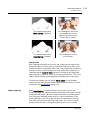
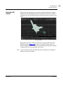
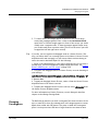
Nuke is an Academy Award® winning compositor. It has been used to create
extraordinary images on scores of feature films, including Avatar, District 9,
Australia, The Dark Knight, Quantum of Solace, The Curious Case of
Benjamin Button, Iron Man, Transformers, Pirates of the Caribbean: At
World’s End, and countless commercials and music videos.
About this User
Guide
This User Guide consists of the following sections:
1. Nuke, which describes key features of Nuke in more detail. You can dip
in and out of this section depending on what you’re interested in.
2. NukeX, which describes the features in NukeX. You can also learn about
the differences between Nuke and NukeX here.
3. Appendices, which include the available hotkeys, supported file formats,
a Shake to Nuke conversion course, and the end user license agreement.
If you are new to Nuke, we recommend that you start by familiarizing
yourself with the Getting Started Guide and working your way through the
Tutorials in it. The Getting Started Guide should give you a good base to
build on when creating your own scripts. For learning about specific
features in Nuke or NukeX, or when you’re looking for an answer to a
specific problem the Nuke User Guide is guide to turn to.
Throughout the User Guide, we assume you have a basic knowledge of
computer graphics and digital compositing theory, as well as proficiency
with the operating system for which Nuke is installed.
Note
For the most up-to-date information, please see the Nuke product page and
the latest Nuke user guide on our web site at www.thefoundry.co.uk.
Getting Help
Viewing Online Help
Nuke features several forms of online help:
• Most controls offer concise instructions in the form of tooltips. To
display the tool tips, move your mouse pointer over an interface control
or a node parameter.
PREFACE
Getting Help
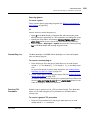
• Many properties panels include contextual descriptions of the node’s
parameters. To display these descriptions, click the ? icon.
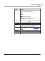
• Finally, you can click the Help menu to access the following:
• Key assignments - a list of hotkeys.
• Documentation - this User Guide, the Getting Started Guide, the Nuke
Reference Guide, the FurnaceCore User Guide, the Nuke Developer Kit
(NDK), and documentation for using FrameCycler, Python, TCL, and
expressions in Nuke.
• Release Notes - a list of new features, feature enhancements, known
issues and developer notes for the most recent Nuke releases.
• Training and tutorials - FX PHD's Compositor's Guide to Nuke training
videos, and a list of other training resources. You can also find grain
samples, and the files used with the tutorials in this user guide.
• Nukepedia - an online knowledge base maintained by experienced
Nuke users, containing downloads, tutorials, interviews and more.
• Mailing lists - information on Nuke-related e-mail lists.
• Plug-in Installer - download plug-ins for Nuke.
Contacting Customer
Support
The Foundry
Should questions arise that this manual or the online help system fails to
address, you can contact Customer Support directly via e-mail at
[email protected] or via telephone to our London office on +44
(0)20 7968 6828 or to our Los Angeles office on (310) 399 4555 during
office hours.
Nuke 7.0v1
20
NUKE
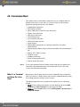
Each chapter in this section explains in detail a key feature of Nuke. You
can use the section to familiarize yourself with the features you are particularly interested in, or to get answers to specific problems that arise during
compositing.
For information on the features in NukeX, see NukeX on page 597.
Organisation of the
Sections
These are the topics covered by this section:
• Chapter 1, Reformatting Elements, describes how you can reformat
images through scaling, cropping, and pixel aspect adjustments. This
chapter also covers working with bounding boxes.
• Chapter 2, Channels, shows you how to manage image data using Nuke’s
unique 1023-channel workflow.
• Chapter 3, Merging Images, teaches you how to layer background and
foreground elements together, create contact sheets, and copy
rectangles from one image to another.
• Chapter 4, Color Correction and Color Space, explains a broad sampling
of Nuke’s many color correction tools.
• Chapter 5, Keying with Primatte, teaches you to use the blue/
greenscreen keyer Primatte in Nuke.
• Chapter 6, Keying with Keylight, teaches you to use the keyer tool
Keylight in Nuke.
• Chapter 7, Keying with Ultimatte, shows you to use the Ultimatte keyer
in Nuke.
• Chapter 8, Using RotoPaint, shows how to use Nuke’s RotoPaint node.
• Chapter 9, Tracking and Stabilizing, shows how to generate and edit 2D
tracking data for purposes of removing unwanted motion or applying it
to other elements.
• Chapter 10, Transforming Elements, covers the tools for changing the
size, location, and orientation of an image, including how to translate,
scale, rotate, and skew elements in 2D and 3D space. This chapter also
describes adding motion blur.
• Chapter 11, Warping and Morphing Images, teaches you to use the
GridWarp and SplineWarp nodes to warp and morph images.
• Chapter 12, Filtering and Spatial Effects, deals with applying filters, such
as convolves and blurs.
• Chapter 13, Creating Effects, describes how you can create effects, such
as star filter effects, on your images.
22
Organisation of the Sections
• Chapter 14, Temporal Operations, explains how to apply time-based
effects like clip retiming and motion blur. This chapter also explains how
to perform editorial tasks, such as trimming and slipping.
• Chapter 15, Analyzing Frame Sequences, explains how to use the
CurveTool node to analyze and match image sequences.
• Chapter 16, Audio in Nuke, covers using audio clips in Nuke.
• Chapter 17, 3D Compositing, teaches you how to create and manipulate
3D scenes composed of objects, materials, lights, and cameras.
• Chapter 18, Deep Compositing, goes through using the deep compositing
node set in Nuke.
• Chapter 19, Working with Stereoscopic Projects, describes how to
composite stereoscopic material in Nuke.
• Chapter 20, Previews and Rendering, teaches you how to write out image
sequences from scripts in order to preview results or create final
elements.
• Chapter 21, Expressions, explains how to apply expressions or scripting
commands to Nuke parameters.
• Chapter 22, The Script Editor and Python takes you through using Nuke’s
Script Editor for executing Python commands.
• Chapter 23, Setting Interface Preferences, discusses the available
preference settings that you can use to make behavior and display
adjustments to the interface.
• Chapter 24, Configuring Nuke, explains how to set up Nuke for multiple
artists working on the same project.
The Foundry
Nuke 7.0v1
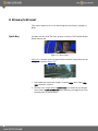
1 REFORMATTING ELEMENTS
This chapter teaches you how to reformat images through scaling, cropping,
and pixel aspect adjustments. You will also learn to adjust bounding boxes
to minimize processing and rendering times.
Reformatting
Images
This section discusses scaling operations with specific regard to
reformatting elements to match specific resolutions and pixel aspect ratios.
Nuke includes at least two nodes designed for reformatting elements:
Reformat, and Crop.
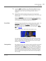
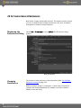
Using the Reformat
Node
You can use the Reformat node for three different purposes:
1. To generate image sequences that match a desired image format in
terms of both resolution and pixel aspect ratio (the width to height ratio
of the format’s individual pixels).
2. To create thumbnails (low resolution frames which you might post to the
web in order to storyboard a sequence). The node scales the frame until
it fits inside a rectangle whose dimensions you specify. It also sets pixel
aspect ratio to one (square).
3. To scale images. The scale factor is rounded slightly so that the output
image has an integer number of pixels in the direction you choose in the
Reformat node’s controls.
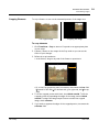
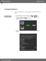
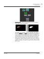
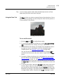
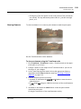
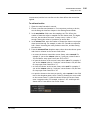
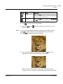
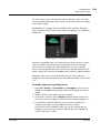
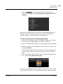
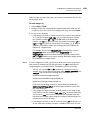
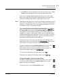
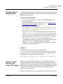
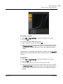
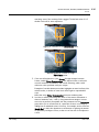
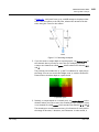
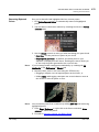
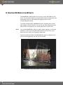
Converting images to a desired image format
When you read in elements, Nuke stores their format settings and makes
them available to the Reformat node. You can then apply one of the existing
formats to your images, or create, edit, and delete formats yourself.
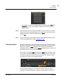
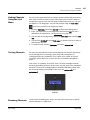
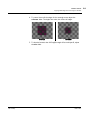
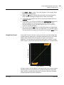
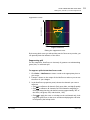
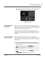
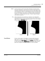
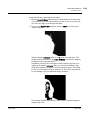
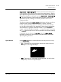
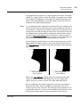
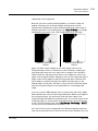
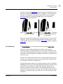
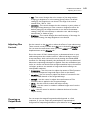
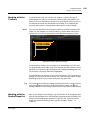
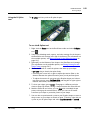
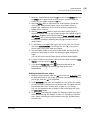
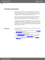
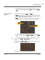
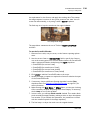
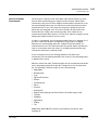
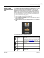
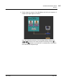
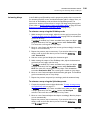
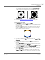
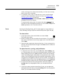
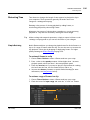
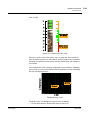
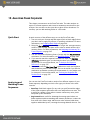
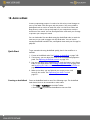
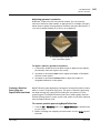
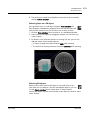
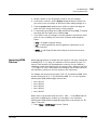
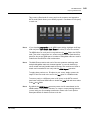
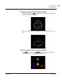
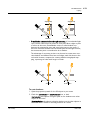
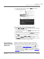
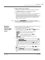
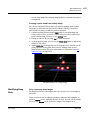
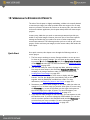
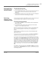
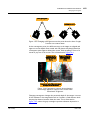
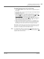
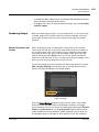
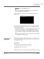
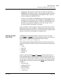
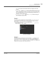
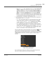
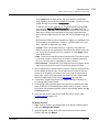
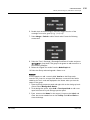
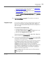
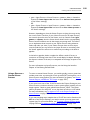
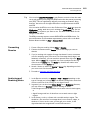
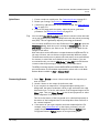
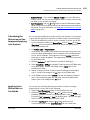
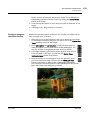
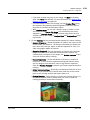
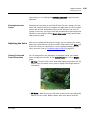
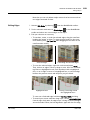
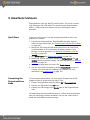
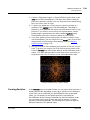
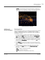
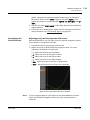
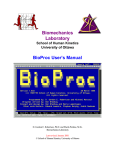
When creating a new format from scratch, you define the overall resolution,
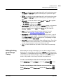
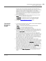
the cropped resolution (optional) and the pixel aspect ratio. As you define
these parameters, the Reformat operator graphically displays them for you
in the manner shown below.
full dimensions
pixel dimensions
crop dimensions—only inside
portion will display as image
REFORMATTING ELEMENTS
Reformatting Images
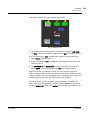
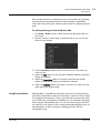
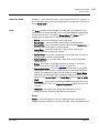
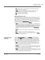
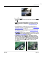
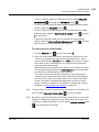
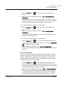
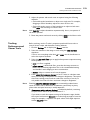
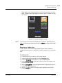
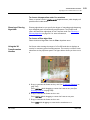
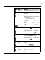
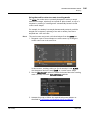
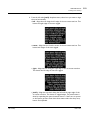
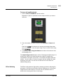
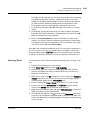
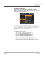
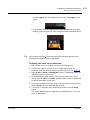
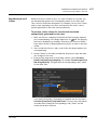
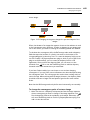
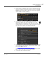
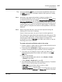
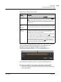
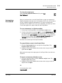
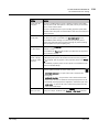
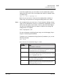
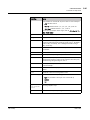
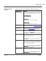
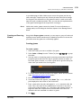
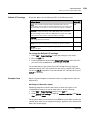
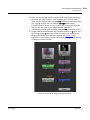
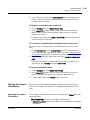
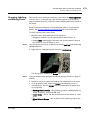
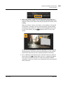
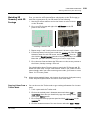
To create a new output format:
1. Click Transform > Reformat to insert a Reformat node at an appropriate place in your script (generally before a Write node).
2. Connect a Viewer to the output of the Reformat node so you can see the
effect of your changes.
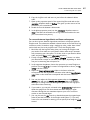
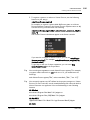
3. Select new from the output format dropdown menu. The New format
dialog appears.
4. Type a name for the new format in the name field.
5. In the file size fields, type the full output resolution (in pixels).
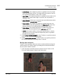
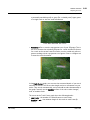
6. If you want to crop the full output resolution (for example, to create a
letter box):
• Check image area.
• Increment the x field to define the left boundary of the crop. (The display updates to show you the left boundary of the crop relative to the
full-size input.)
• Increment the y field to define the bottom boundary of the crop.
• Increment the r field to define the right boundary of the crop.
• Increment the t field to define the top boundary of the crop.
7. If the destination display device for the image sequence uses nonsquare
pixels, type the appropriate pixel aspect ratio in the pixel aspect field
(for example, if your destination is a digital video display, type 1.1).
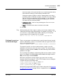
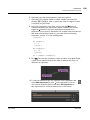
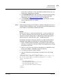
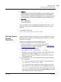
Tip
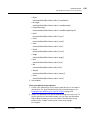
You can also add formats to Nuke via entries to the menu.py file:
1. Open the menu.py file (located in same directory as your Nuke
executable).
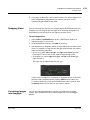
2. Add an entry similar to the following example:
nuke.addFormat ("720 486 0 0 720 486 0.9 NTSC_video")
where the numbers specify, respectively, the format’s full horizontal
resolution, full vertical resolution, left crop position, bottom crop position,
right crop position, top crop position, and pixel aspect ratio; and where the
final text string designates the format’s name.
3. Save and close the menu.py file. The next time you launch Nuke the
format is available for selection from the Project Settings dialog, Reformat
node properties panel, and elsewhere.
The Foundry
Nuke 7.0v1
24
REFORMATTING ELEMENTS
Reformatting Images
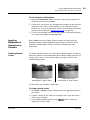
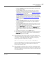
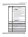
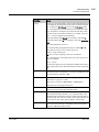
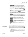
To edit a format:
1. Select the format you wish to edit from the output format dropdown
menu.
2. From the same dropdown menu, select edit. The Edit format dialog
appears.
3. Edit the name, file size, image area, and pixel aspect fields as
necessary.
4. Click OK to save the changes to the format.
To delete a format:
1. Select the format you wish to delete from the output format dropdown
menu.
2. From the same dropdown menu, select delete. The format is removed
from the menu.
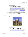
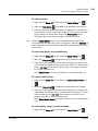
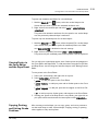
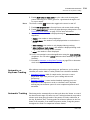
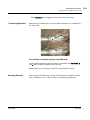
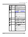
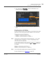
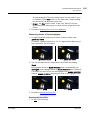
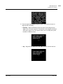
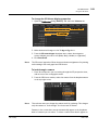
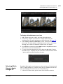
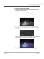
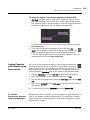
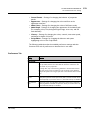
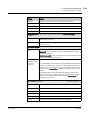
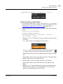
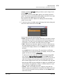
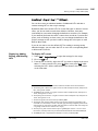
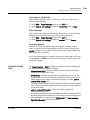
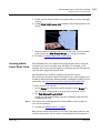
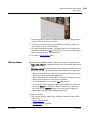
To apply a format:
1. If necessary, click Transform > Reformat to insert a Reformat node at
an appropriate place in your script (generally before a Write node).
2. Connect a Viewer to the output of the Reformat node so you can see the
effect of your changes.
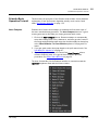
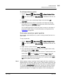
3. From the type dropdown menu, select to format.
4. Select the format you wish to apply from the output format dropdown
menu.
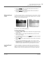
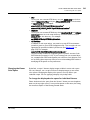
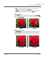
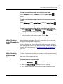
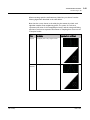
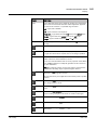
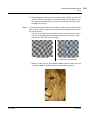
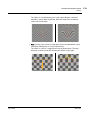
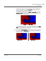
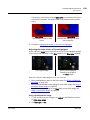
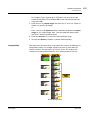
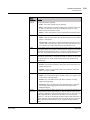
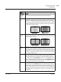
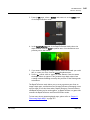
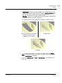
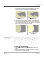
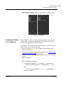
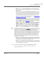
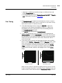
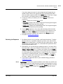
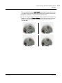
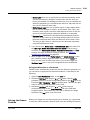
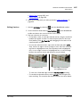
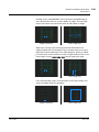
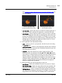
5. From the resize type field, choose the method by which you want to
preserve or override the original aspect ratio. Select:
• width to scale the original until its width matches the format’s width.
Height is then scaled in such a manner as to preserve the original
aspect ratio.
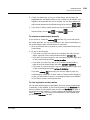
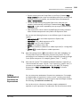
• height to scale the original until its height matches the format’s height.
Width is then scaled in such a manner as to preserve the original
aspect ratio.
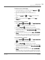
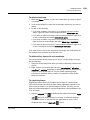
• fit to scale the original until its smallest side matches the format’s
smallest side. The original’s longer side is then scaled in such a manner
as to preserve original aspect ratio.
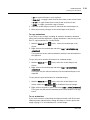
• fill to scale the original until its longest side matches the format’s longest side. The input’s shorter side is then scaled in such a manner as
to preserve original aspect ratio.
The Foundry
Nuke 7.0v1
25
REFORMATTING ELEMENTS
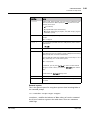
Reformatting Images
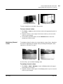
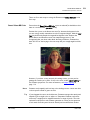
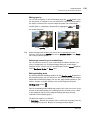
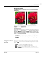
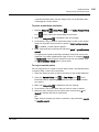
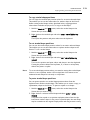
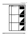
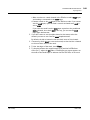
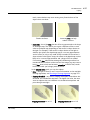
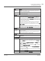
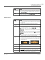
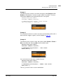
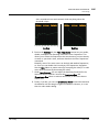
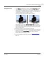
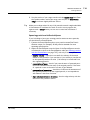
• distort to scale the original until all its sides match the lengths specified by the format. This option does not preserve the original aspect
ratio, so distortions may occur.
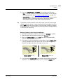
6. When cropping the output, check center to position the crop area at
the center of the frame.
7. Choose the appropriate filtering algorithm from the filter dropdown
menu (see Choosing a Filtering Algorithm on page 241).
8. When scaling an image with Key, Simon, and Rifmen filters, you may see
a haloing effect which is caused by pixel sharpening these filters employ.
If necessary, check clamp to correct this problem.
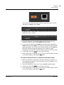
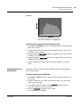
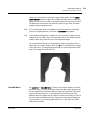
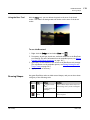
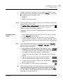
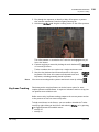
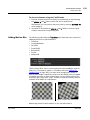
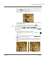
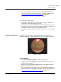
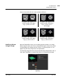
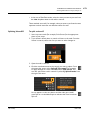
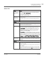
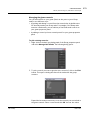
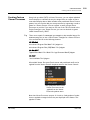
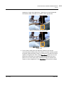
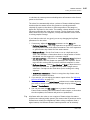
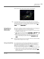
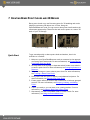
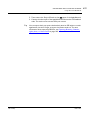
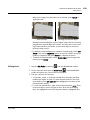
Creating thumbnails
1. Click Transform > Reformat to insert a Reformat node at an appropriate
place in your script (generally before a Write node).
2. Connect a Viewer to the output of the Reformat node so you can see the
effect of your changes.
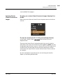
3. From the type dropdown menu, select to box.
4. In the width and height fields, type the output dimensions. The units are
pixels.
5. Use the resize type dropdown menu to choose the method by which
you preserve or override the original pixel aspect ratio. Select:
• width to scale the original until its width matches the value in the
width field. Height is then scaled in such a manner as to preserve the
original aspect ratio (this means that the output you specified in
height may not match the result).
• height to scale the original until its height matches the value in the
height field. Width is then scaled in such a manner as to preserve the
original aspect ratio (this means that the output you specified in width
may not match the result).
• fit to scale the original until its smallest side matches the corresponding value in width/height. The longer side is then scaled in such a manner as to preserve the original aspect ratio.
• fill to scale the original until its longest side matches the corresponding value in width/height. The smallest side is then scaled in such a
manner as to preserve the original aspect ratio.
• distort to scale the original until its sides match the values in the
width/height fields. This option does not preserve the original aspect
ratio, so distortions may occur.
6. Choose the appropriate filtering algorithm from the filter dropdown
menu (see Choosing a Filtering Algorithm on page 241).
The Foundry
Nuke 7.0v1
26
REFORMATTING ELEMENTS
Reformatting Images
7. When scaling an image with Key, Simon, and Rifmen filters, you may see
a haloing effect which is caused by pixel sharpening these filters employ.
If necessary, check clamp to correct this problem.
Scaling image sequences
1. Click Transform > Reformat to insert a Reformat node at an appropriate
place in your script (generally before a Write node).
2. Connect a Viewer to the output of the Reformat node so you can see the
effect of your changes.
3. From the type dropdown menu, select scale.
4. In the scale fields, enter scale factors for the width and the height. To
scale each direction separately using different scale factors, click the 2
button.
5. Use the resize type dropdown menu to choose the method by which
you preserve or override the original pixel aspect ratio. Select:
• width to scale the original so that it fills the output width. Height is
then scaled in such a manner as to preserve the original aspect ratio.
• height to scale the original so that it fills the output height. Width is
then scaled in such a manner as to preserve the original aspect ratio.
• fit to scale the original so that its smallest side fills the output width
or height. The longest side is then scaled in such a manner as to preserve the original aspect ratio.
• fill to scale the original so that its longest side fills the output width or
height. The smallest side is then scaled in such a manner as to preserve the original aspect ratio.
• distort to scale the original so that both sides fill the output dimensions. This option does not preserve the original aspect ratio, so distortions may occur.
6. Choose the appropriate filtering algorithm from the filter dropdown
menu (see Choosing a Filtering Algorithm on page 241).
7. When scaling an image with Key, Simon, and Rifmen filters, you may see
a haloing effect which is caused by pixel sharpening these filters employ.
If necessary, check clamp to correct this problem.
The Foundry
Nuke 7.0v1
27
REFORMATTING ELEMENTS
Reformatting Images
Cropping Elements
To crop a frame is to cut out the unwanted portions of the image area.
The original image.
Cropping the image.
To crop elements
1. Click Transform > Crop to insert a Crop node at an appropriate place
in your script.
2. Connect a Viewer to the output of the Crop node so you can see the
effect of your changes.
3. Define the crop boundaries:
• In the Viewer, drag on any side of the frame to reposition it.
• Or, in the Crop properties panel, increment or decrement the box field
(x stands for left side, y for bottom side, r for right side, and t for top
side).
4. To fill the cropped portion with black, check black outside. To fill the
cropped portion by expanding the edges of the image, uncheck black
outside. To adjust the image output format to match the cropped
image, check reformat.
5. If you wish to vignette the edges of the cropped portion, increment the
softness field.
The Foundry
Nuke 7.0v1
28
REFORMATTING ELEMENTS
Adjusting the Bounding Box
Adjusting the
Bounding Box
The bounding box defines the area of the frame that Nuke sees as having
valid image data. The larger the bounding box is, the longer it takes Nuke to
process and render the images. To minimize processing and rendering times,
you can crop the bounding box. Occasionally, the bounding box may also be
too small, in which case you need to expand it.
To adjust the bounding box, you can use the AdjBBox and CopyBBox nodes.
The AdjBBox node lets you both crop and expand the bounding box edges,
whereas with the CopyBBox node you can copy a bounding box from one
input to another. If needed, you can also add a black outside edge to the
bounding box using the BlackOutside node.
Resizing the Bounding
Box
The AdjBBox node lets you expand or crop the edges of the bounding box by
a specified number of pixels.
An expanded bounding box.
A cropped bounding box.
For example, if you have an image with lots of black (0,0,0,0), you can
adjust the bounding box to contain just the useful area so that Nuke won’t
waste time computing results where there is no change.
.
The Foundry
Nuke 7.0v1
29
REFORMATTING ELEMENTS
Adjusting the Bounding Box
To resize the bounding box
1. Select Transform > AdjustBBox to insert an AdjBBox node after the
image whose bounding box you want to resize.
2. Connect a Viewer to the AdjBBox node, so you can see the effect of your
changes.
3. In the AdjBBox controls, adjust the Add Pixels slider to increase or
decrease the size of the bounding box. By default, 25 pixels are added
to the edges of the bounding box.
Nuke expands or crops the edges of the bounding box. If the bounding
box is cropped, whatever is outside the bounding box area gets replicated towards the edges of the image.
Copying a Bounding
Box from One Input to
Another
The Foundry
Some Nuke operations, such as a merge, can cause an expansion of the
bounding box area because Nuke does not know that the extra area is going
to be black or another constant color. Often, you can fix this by copying the
bounding box from one of the inputs to the resulting image, thus cutting off
this extra area. For this, you can use the CopyBBox node.
Nuke 7.0v1
30
REFORMATTING ELEMENTS
Adjusting the Bounding Box
A bounding box from one input
copied on top of another.
To copy a bounding box
1. Select Merge > CopyBBox to insert a CopyBBox node after the node
whose bounding box you want to use.
2. Connect the image whose bounding box you want to copy to the
CopyBBox node’s input A, and the image onto which you want to copy
the bounding box to input B.
Nuke copies the bounding box from input A to input B. Whatever is outside the copied bounding box area in image B gets replicated towards
the edges of the image.
The Foundry
Nuke 7.0v1
31
REFORMATTING ELEMENTS
Adjusting the Bounding Box
Adding a Black Outside
Edge to the Bounding
Box
If you adjust a bounding box with the AdjBBox or CopyBBox node, you may
notice that whatever is outside the bounding box area gets replicated
towards the edges of the image. If necessary, you can remove these
replicated edge pixels and fill everything outside the bounding box area with
black. To do this, use the BlackOutside node.
A cropped bounding box with
replicated edges.
The effect of the BlackOutside
node.
To add a black outside edge to the bounding box
1. Select the image whose edges outside the bounding box you want to fill
with black.
2. Choose Transform > BlackOutside to add a BlackOutside node in an
appropriate place in your script.
Nuke fills everything outside the bounding box area with black.
The Foundry
Nuke 7.0v1
32
2 CHANNELS
Digital images generally consist of the four standard channels: red, green,
blue, and alpha. Nuke allows you to create or import additional channels as
masks, lighting passes, and other types of image data. A Nuke script can
include up to 1023 uniquely named channels per compositing script.
For example, you can combine multiple render passes from a 3D scene—an
image from the red, green, and blue channels, a depth mask (z-depth
channel), a shadow pass, a specular pass, lighting passes, and multiple
mattes all stored within one image sequence in your composite.
Quick Start
As a quick overview, here’s the use of channels in a nutshell:
1. Channels in Nuke are always a part of a channel set. You can create new
channels and channel sets using the new option in the channel selection
dropdown menus (such as output and mask) in a node’s properties
panel. For more information, see Creating Channels and Channel Sets on
page 34.
2. Using the channel selection controls you can choose which channels the
node is processing and outputting, or using as a mask when color
correcting for instance. For more information, see Calling Channels on
page 35 and Selecting Masks on page 38.
3. The channels can also be linked to other channel controls through the
Link menu. For more information, see Linking Channels Using the Link
Menu on page 40.
4. Using the Shuffle and ShuffleCopy nodes, you can rearrange your input
channels and apply the result in the output. For more information, see
Swapping Channels on page 41.
Understanding
Channels
Think of a channel as a container that contains image data. Once created or
read into your composite, the image data stored in a channel is available
downstream in the network until the value is replaced with something else
or the channel is removed. The channel may even be “empty”—depending on
where you reference it in the compositing network.
CHANNELS
Understanding Channel Sets (Layers)
Understanding
Channel Sets
(Layers)
All channels in a script must exist as part of channel set (also called a layer).
You’re probably familiar with the default channel set—rgba—which includes
the channels with pixel values of red, green, and blue, and also the alpha
channel for transparency.
All channels in a composite must belong to at least one channel set. Some
channels, like alpha, may be available in other sets, too. Channel names
always include the channel set name as a prefix, like this:
set_name.channel_name.
By default, every script has a channel set called rgba. When you first import
an image element, Nuke automatically assigns its channels to the rgba set—
that is, the image channels are named rgba.red, rgba.blue, rgba.green, and
rgba.alpha.
The rgba set allows for the standard four-channel workflow of most nodebased compositing systems. However, you’re not limited to these four
channels. You can create new channels and assign them to new channel sets
up to the limit of 1023 channels per script.
Creating Channels
and Channel Sets
It’s important to understand that many types of nodes allow you to direct
their output to a specific channel and parent channel set. You have the
option of processing these channels in each subsequent node, or leaving
them unchanged.
Many nodes feature an output or channels setting, which lets you direct
the output of the current node to a specific channel set and channel. You
can also use the output or channels dropdown menu to create new channel
sets and channels.
Some nodes do not include an output or channels setting in their
parameters. For these, you can connect other nodes, such as Channel Copy
or Shuffle, to create and manage channel output in the node tree.
To create a new channel set and/or channel
1. Open the properties panel for the node whose output creates the new
channel.
2. From the output or channels dropdown menu, select new.
3. Under Name, enter the name of the channel set, and under Channels
the new channel name.
The Foundry
Nuke 7.0v1
34
CHANNELS
Calling Channels
For example, as shown in the figure above, you would enter robot and
robotvisor to create a new channel (“robotvisor”) in the channel set
named “robot.”
Note
You can either use a new channel set name to create a new set, or enter a
channel set you’ve created previously. You can’t create new channels into
channel sets that are built into Nuke (such as mask).
4. Click OK.
Note
Calling Channels
You can also create new channels with the Shuffle and ShuffleCopy nodes.
These are explained later, under Swapping Channels.
By default, most nodes in Nuke attempt to process the current channels in
the rgba set and place the output in those same channels. However, many
nodes also contain an input dropdown menu which lets you select the
channels you want to process, and an output dropdown menu to choose the
channel(s) where the results should be stored.
Some nodes also contain mask controls and a mask input connector, which
let you select a channel for use as a matte to limit operations such as color
corrections. Using these mechanisms, you can point the output of almost
any node in the script to any available channel.
input channels
output channel
The script below attempts to clarify these concepts. Note the script
generates six channels (though it could just as well generate 1023). The
The Foundry
Nuke 7.0v1
35
CHANNELS
Calling Channels
steps below describe how each channel was created.
A
B
C
D
A six-channel script.
A. The script reads in the foreground, creating three channels (red, green,
and blue), which are by default assigned to the rgba set. Channel count: 3
B. A low contrast key (soft) is pulled and assigned to a new channel set
called mattes. Channel count: 4
C. A high contrast key (hard) is pulled and also assigned to the mattes set.
Channel count: 5
D. The mattes.hard and mattes.soft channels are mixed to form the final
matte (alpha), which is assigned to the rgba set. Channel count: 6
Suppose now that you wanted to perform a color correction using the
output of the Soft Matte node as a mask for the correction. There’s no need
to pipe the output from that Soft Matte node—it already exists in the data
stream along with the other five channels that were created.
You simply attach a color correction node (for example, the HueCorrect
node), then select the appropriate channel from the mask controls (in this
example, mattes.soft). (Again, the mattes portion of the name indicates the
The Foundry
Nuke 7.0v1
36
CHANNELS
Calling Channels
parent channel set.)
Selecting a channel to mask color
correction.
Viewing Channels in
the Viewer
You can view the individual red, green, blue, and alpha channels in the
Viewer using the R, G, B, and A keys on the keyboard. For more information,
see the Viewers section in the Using the Interface chapter of the Nuke
Getting Started Guide.
Selecting Input
Channels
A node’s channels field lets you select one or several channels for
processing.
To select a single input channel
1. Open the properties panel of the node into which you wish to feed a
channel.
2. From the channels field, select none.
3. From the right most channel field—the one which typically calls the
alpha channel—select the single channel you wish to process.
Single channel
To select multiple input channels
1. Open the properties panel of the node into which you wish to feed channels.
2. From the channels field, select the channel set containing the channels
you wish to process.
The set’s channels appear with check boxes.
The Foundry
Nuke 7.0v1
37
CHANNELS
Calling Channels
selected channel set
available channels
3. Uncheck those channels which you don’t wish to process. The node
processes all those you leave checked.
Selecting Masks
The mask controls in a node’s properties panel let you select a single
channel for use as a matte in a given process (typically, a color correction).
The given process thereafter is limited to the non-black areas of the
selected channel.
You can use one of the script’s existing channels as the matte, or attach a
mask to the node with a mask input connector.
You can find mask input connectors on color correction and filter nodes,
such as HueCorrect and Blur. At first, they appear as triangles on the right
side of the nodes, but when you drag them, they turn into arrows labeled
mask. You connect them the same way as any other connectors. If you
cannot see a mask input connector, open the node’s properties panel and
make sure mask is set to none.
Before dragging the mask
input connector.
When dragging the mask
input connector.
To select a channel for use as a matte from the mask input
1. Connect a mask to the node with its mask input connector.
The Foundry
Nuke 7.0v1
38
CHANNELS
Calling Channels
If you cannot see the mask input connector, open the node’s controls
and make sure mask is set to none.
By default, when a mask input is connected, the node uses the alpha
channel from it as a matte.
2. If you don’t want to use the alpha channel as the matte, select the
channel you want to use from the mask dropdown menu.
3. If you want the mask from the mask input copied into the predefined
mask.a channel, check inject. This way, you can use the last mask input
again downstream. You can also set a stream of nodes to use mask.a as
the mask, and then change the masking of all of them by simply
connecting a new mask into the mask input connector of the first node.
4. If necessary, check the invert box to reverse the mask.
5. If the overall effect of the node is too harsh, you can blend back in some
of the input image by adjusting the mix slider.
To select a channel for use as a matte from the main input
1. Make sure nothing is connected to the node’s mask input connector. If
you disconnect a mask input, the mask input connector disappears, as it
is no longer being used.
2. Select the channel you want to use from the mask dropdown menu.
3. If necessary, check the invert box to reverse the mask.
4. If the overall effect of the node is too harsh, you can blend back in some
of the input image by adjusting the mix slider.
The Foundry
Nuke 7.0v1
39
CHANNELS
Linking Channels Using the Link Menu
Linking Channels
Using the Link
Menu
You can create expression links to connect channel and channel set controls
with other controls in various nodes. Since these controls aren’t meant to
be animated, you can’t use the full range of Nuke expressions, nor can you
use Python or TCL languages. You can link controls using the Link menu
next to the control on the properties panel:
1. Click the Link menu and select Set link. An Expression dialog opens.
2. Enter your expression in the Expression field and click OK. For more
information on expressions, see Expressions on page 503.
3. You can edit an existing link by clicking the Link menu and selecting Edit
link.
4. You can also Ctrl/Cmd+drag the Link menu to another control to create a
link between the two.
5. To remove a link, click the Link menu and select Remove link.
Tracing Channels
You may have noticed that nodes visually indicate the channels which they
are processing (that is, treating in some way) and passing (that is,
conveying without any treatment). This is done via a system of colored
rectangles, which allows you to trace the flow of channels throughout a
script.
Look closer, for example, at the Over node. The wide rectangles indicate
channels which Nuke processes (in this case, the red, green, blue, and alpha
channels). The narrow rectangles indicate channels that Nuke passes onto
the next node without processing (in this case, the mattes.soft and
mattes.hard).
Visual confirmation of extra
channels.
Renaming Channels
The Foundry
In the course of building your script, you may find it necessary to replace
certain channels in a channel set.
Nuke 7.0v1
40
CHANNELS
Removing Channels and Channel Sets
To rename a channel
1. Open the properties panel for a node which has the channel selected on
the channels, input, or output dropdown menu.
2. Click on the dropdown menu where the channel is displayed and choose
rename.
The Rename Channel box appears.
3. Enter a new name for the channel and click OK.
Removing Channels
and Channel Sets
When you are done using a channel set or a channel within a set, you may
wish, for the sake of clarity, to remove it so that it is no longer passed to
downstream nodes. Note that leaving channels in the stream does not itself
cause them to be computed, only channels required are computed.
To remove a channel set or a channel within a set
1. Click Channel > Remove to insert a Remove node at the appropriate
point in your script.
2. In the Remove properties panel, select the channel set you wish to
remove from the channels fields.
3. If you don’t wish to remove the entire channel set, uncheck the boxes
corresponding to the channels which you still wish to be able to call
downstream.
4. Click OK to close the properties panel.
The channel set and/or the channels you removed are no longer displayed in node parameters downstream from the Remove node.
Note
Swapping Channels
The Foundry
Removing channel sets and or channels does not free up space for the
creation of new channels and sets. Once you create a channel it
permanently consumes one of the script’s 1023 available channel name
slots. You are free, however, to rename channels and/or assign them new
outputs.
Nuke features two main nodes for channel swapping: Shuffle and
ShuffleCopy. Shuffle lets you rearrange the channels from a single image (1
input) and then output the result to the next node in your compositing tree.
ShuffleCopy lets you rearrange channels from two images (2 inputs) and
Nuke 7.0v1
41
CHANNELS
Swapping Channels
output the result. Let’s take a look at the ShuffleCopy node first.
Channels from input 1
Channels from input 2
The channel set the
channels are output to
Matrix combination
specifies channels
to output
The ShuffleCopy matrix.
Channels from Input 1
The first group of channel boxes are the channels supplied by input 1 on the
node. As shown above, the foreground element’s default rgba set is
selected.
Channels from Input 2
The second group of channel boxes are the channels supplied by input 2 on
the node.
Channel Outputs
The combination of the boxes checked in the channel matrix create the list
of channels that are output to the channel set selected in the top dropdown
menu on the right.
This four channel stream acts as the second set of outputs from the node. It
allows you to output another four channels from the node, for a total of
eight channels of output to match the possible eight channels of input.
In this case, this second set of outputs has not been utilized.
Tip
The Foundry
While not required, it’s good practice to use the first set of outputs for
swapping channels in the current data stream and the second set of outputs
for creating new channels. This protects the default rgba set from
unintentional overwriting, and makes it easier for other artists to
understand the workings of your script.
Nuke 7.0v1
42
CHANNELS
Swapping Channels
The basic process then for swapping channels is to first select your
incoming channel sets from the 1 in and 2 in (or, in the case of the Shuffle
node, the in 1 and in 2) dropdown menus. Then, select your outgoing
channel sets from the dropdown menus on the right. Then make the actual
channel swaps by clicking on the resulting matrix.
For example, to take the simplest case, suppose, you wanted to copy red
channel of the rgba set into its alpha channel. You would click on the matrix
to create the following configuration.
Configuring the channel matrix.
You can see that the matrix makes use of the r channel (standing for red)
twice. It goes out once as the red channel, and another time as the alpha
channel.
Assigning Constants
The shuffle nodes also include parameters that let you assign white (1) or
black (0) constants to any incoming channel. So, for example, to reset the
alpha channel to a full-frame image, you would configure the matrix as
follows:
Assigning constants to channels.
Creating Swap Channel
Sets
The Foundry
Finally, note that if the channel set to which you wish to output channels
does not yet exist, you can create it using the new option on the dropdown
menus on the right. Once you select the new option, you follow the same
process for creating channel sets as is described in the Creating Channels
and Channel Sets on page 34.
Nuke 7.0v1
43
CHANNELS
Swapping Channels
Swapping channels
To swap channels, do the following:
1. Click Channel > Shuffle or ShuffleCopy to insert a Shuffle or ShuffleCopy node. Remember you use Shuffle when you only want to swap
channels in a single upstream node, and ShuffleCopy when you want to
swap channels in two separate nodes, like a foreground and background
branch.
2. Select the incoming channels from the In 1 and In 2 (optional) dropdown
menus. You can select up to eight channels in this manner.
3. Select the channel sets to which you wish to direct the incoming
channels from the dropdown menus on the right. You can select up to
eight channels in this manner.
4. If the outgoing channel set to which you wish to direct channels does
not yet exist, create it using the new option on the dropdown menus on
the right.
5. Click as necessary on the resulting matrix to swap channels.
Tip
The Foundry
If you just need to copy a channel from one data stream into another, use
Channel > Copy, instead of ShuffleCopy. Then, specify the channel to copy
and the destination channel for output.
Nuke 7.0v1
44
3 MERGING IMAGES
With Nuke, you can merge images in a wide variety of ways. In this chapter,
we teach you how to use the Merge, ContactSheet, and CopyRectangle
nodes. The Merge node is used for layering multiple images together. The
ContactSheet node lets you create a contact sheet that shows your frame
sequence(s) lined up next to each other in a matrix. The CopyRectangle
node can be used for copying a rectangular region from one image to
another.
Quick Start
1. When you merge images, you layer them together in various ways. To
get started, you need to create a Merge node (Merge > Merge).
2. The Merge node takes two default inputs, A and B, and any number of
optional numbered A inputs and layers them together. Connect your
images to these inputs. Layering Images Together with the Merge Node
on page 45.
3. Choose a merge operation in the operation dropdown in the properties
panel. For more information, see Merge Operations on page 47.
Layering Images
Together with the
Merge Node
The Merge node with its compositing algorithms allows you to control just
how your images are combined.
Note
When using most of the available merge algorithms, Nuke expects
premultiplied input images. However, with the matte operation you should
use unpremultiplied images.
To layer images with the Merge node
1. Select Merge > Merge (or press M on the Node Graph) to insert a
Merge node after the images you want to layer together.
2. Connect your images to the Merge node’s A and B inputs.
3. If necessary, you can connect multiple A images to the Merge node.
Once you have got the A and B inputs connected as instructed in step 2,
drag more connectors from the left side of the Merge node to the
images you want to use as additional A inputs.
Each input is merged in the order connected, for example A1, A2, A3, B.
MERGING IMAGES
Layering Images Together with the Merge Node
4. Connect a Viewer to the output of the Merge node so you can see the
effect of your merge operation.
5. In the Merge node’s controls, select how you want to layer the images
together from the operation dropdown menu. The default and the most
common operation is over, which layers input A over input B according
to the alpha of input A. For descriptions of all the available operations,
see Merge Operations below.
6. Using the A channels and B channels dropdown menus, select which
channels to use from the A and B inputs and which channels to use as
the A and B alpha. If you want to merge more channels than these and
output them into the same channels, select them from the also merge
dropdown menus and checkboxes.
7. From the output dropdown menu, select the channels you want to write
the merge of the A and B channels to. Channels named in the also
merge dropdown menu are written to the same output channels.
8. If necessary, you can also adjust the following controls:
• To select which input’s metadata to pass down the tree, use the metadata from dropdown menu. For more information on file metadata,
see “Working with File Metadata” in the Managing Scripts chapter of
the Getting Started Guide.
• To dissolve between the original input B image (at 0) and the full
Merge effect (at 1), adjust the mix slider. A small light gray square
appears on the node in the node graph to indicate that the full effect
is not used.
• If you want to mask the effect of the Merge operation, select the mask
channel from the mask dropdown menus. To invert the mask, check
invert. To blur the edges of the mask, check fringe.
Note that you should not use the alpha of the inputs for the mask. It
produces erroneous results (though the error is often hard to see); you
can achieve better results by turning on alpha masking.
• From the Set BBox to dropdown menu, select how you want to output
the bounding box. The default is union, which combines the two
bounding boxes. You can also choose intersection to set the bounding box to the area where the two bounding boxes overlap, A to use
the bounding box from input A, or B to use the bounding box from
input B.
• By default, Nuke assumes that images are in linear color space. However, if you want to convert colors to the default 8-bit color space
defined in the LUT tab of your project settings (usually, sRGB), check
Video colorspace. The conversion is done before the images are
composited together, and the results are converted back to linear
The Foundry
Nuke 7.0v1
46
MERGING IMAGES
Layering Images Together with the Merge Node
afterwards. Any other channels than the red, green, and blue are
merged without conversion.
Checking this option can be useful if you want to duplicate the results
you obtained from an application that uses the standard compositing
math but applies it to non-linear images (for example, Adobe® Photoshop®). In this case, you typically also need to make sure premultiplied is not checked in your Read node controls.
• By default, the same math is applied to the alpha channel as the other
channels. However, according to the PDF/SVG specification, many of
the merge operations (for example, overlay and hard-light) should set
the alpha to (a+b - ab). This way, the input images remain unchanged
in the areas where the other image has zero alpha. If you want to
enable this, check alpha masking.
Merge Operations
When layering images with the Merge node, you need to select a
compositing algorithm that determines how the pixel values from one input
are calculated with the pixel values from the other to create the new pixel
values that are output as the merged image.
The operation dropdown menu in the Merge node’s properties panel
houses a large number of different compositing algorithms, giving you great
flexibility when building your composite. The available algorithms are listed
in alphabetical order.
Tip
With many compositing algorithms available, it may sometimes be difficult
to find what you’re looking for in the operation dropdown menu. Luckily,
there’s a quick way of finding a particular operation. With the menu open,
you can type a letter to jump to the first operator that starts with that
letter. To move to the second operation that starts with the same letter,
press the letter again. For example, to select the soft-light operation, open
the menu and press S twice.
The following table describes each operation and its associated compositing
algorithm. There are example images to illustrate the effects, one that
combines the letters A and B to a merged image and another that has an
image of fire merged with the familiar checkerboard. You may want to spend
some time familiarizing yourself with each algorithm in order to be able to
determine which operation to use in each situation.
The Foundry
Nuke 7.0v1
47
MERGING IMAGES
Layering Images Together with the Merge Node
Operation Algorithm Description
The Foundry
atop
Ab+B(1a)
Shows the shape of image B,
with A covering B where the
images overlap.
average
(A+B)/2
The average of the two
images. The result is darker
than the original images.
colorburn
darken B Image B gets darker based on
towards the luminance of A.
A
Illustration
Example Uses
Nuke 7.0v1
48
MERGING IMAGES
Layering Images Together with the Merge Node
Operation Algorithm Description
colordodge
brighten
B
towards
A
Illustration
Example Uses
Image B gets brighter based
on the luminance of A.
conjoint- A+B(1-a/ Similar to the over operation,
over
b),
except that if a pixel is parA if a>b tially covered by both A and B,
conjoint-over assumes A completely hides B. For instance,
two polygons where A and B
share some edges but A completely overlaps B. Normal
over produces a slightly transparent seam here.
copy
The Foundry
A
Only shows image A.
This is useful if you
also set the mix or
mask controls so
that some of B can
still be seen.
Nuke 7.0v1
49
MERGING IMAGES
Layering Images Together with the Merge Node
Operation Algorithm Description
difference abs(A-B)
disjointover
How much the pixels differ.
Also available from Merge >
Merges > Absminus.
A+B(1-a)/ Similar to the over operation,
b,
except that if a pixel is partially covered by both a and b,
A+B if
disjoint-over assumes the two
a+b<1
objects do not overlap. For
instance, two polygons that
touch and share an edge. Normal over produces a slightly
transparent seam here.
Illustration
Example Uses
Useful for comparing two very similar
images.
This can be useful if
you want to merge
element a over element b, and element
a has element b
already held out. For
example, you may
have a CG character
whose hair, skin, and
clothing are rendered
separately so that
each object has the
other objects held
out of the render.
In this case, using
the over operation
would produce dark
lines around the
comped objects. This
is because over does
a hold-out of the
background image,
meaning the background is held out
twice.
The Foundry
Nuke 7.0v1
50
MERGING IMAGES
Layering Images Together with the Merge Node
Operation Algorithm Description
divide
A/B,
0 if A<0
and B<0
Divides the values but stops
two negative values from
becoming a positive number.
Illustration
Example Uses
This does not match
any photographic
operation, but can be
used to undo a multiply.
exclusion A+B-2AB A more photographic form of
difference.
from
The Foundry
B-A
Image A is subtracted from B.
Nuke 7.0v1
51
MERGING IMAGES
Layering Images Together with the Merge Node
Operation Algorithm Description
geometric 2AB/
(A+B)
Illustration
Example Uses
Another way of averaging two
images.
hard-light multiply if Image B is lit up by a very
A<0.5,
bright and sharp light in the
screen if shape of image A.
A>0.5
hypot
sqrt
Resembles the plus and screen
(A*A+B*B) operations. The result is not
as bright as plus, but brighter
than screen.
This is useful for
adding reflections, as
an alternative to
screen.
Hypot works with values
above 1.
The Foundry
Nuke 7.0v1
52
MERGING IMAGES
Layering Images Together with the Merge Node
Operation Algorithm Description
The Foundry
in
Ab
Only shows the areas of image
A that overlap with the alpha
of B. Also available from
Merge > Merges > In.
mask
Ba
This is the reverse of the in
operation. Only shows the
areas of image B that overlap
with the alpha of A.
matte
Aa+B(1a)
Premultiplied over. Use unpremultiplied images with this
operation. Also available from
Merge > Merges > Matte.
Illustration
Example Uses
Useful for combining
mattes.
Nuke 7.0v1
53
MERGING IMAGES
Layering Images Together with the Merge Node
Operation Algorithm Description
The Foundry
max
max (A,B) Takes the maximum values of
both images. Also available
from Merge > Merges > Max.
min
min (A,B) Takes the minimum values of
both images. Also available
from Merge > Merges > Min.
minus
A-B
Illustration
Example Uses
This is a good way to
combine mattes and
useful for bringing
aspects like bright
hair detail through.
Image B is subtracted from A.
Nuke 7.0v1
54
MERGING IMAGES
Layering Images Together with the Merge Node
Operation Algorithm Description
multiply
AB, A if
A<0 and
B<0
Multiplies the values but stops
two negative values from
becoming a positive number.
Also available from Merge >
Merges > Multiply.
Illustration
Example Uses
Used to composite
darker values from A
with the image of B dark gray smoke shot
against a white background, for example.
This is also useful for
adding a grain plate
to an image
regrained with
F_Regrain.
The Foundry
out
A(1-b)
Only shows the areas of image
A that do not overlap with the
alpha of B. Also available from
Merge > Merges > Out.
over
A+B(1-a) This is the default operation.
Layers image A over B according to the alpha of image A.
Useful for combining
mattes.
This is the most
commonly used operation. Used when
layering a foreground
element over a background plate.
Nuke 7.0v1
55
MERGING IMAGES
Layering Images Together with the Merge Node
Operation Algorithm Description
overlay
Illustration
Example Uses
multiply if Image A brightens image B.
B<0.5,
screen if
B>0.5
Figure
3.1:
The Foundry
plus
A+B
The sum of image A and B.
Also available from Merge >
Merges > Plus. Note that the
plus algorithm may result in
pixel values higher than 1.0.
Useful for compositing laser beams, but
you’re better off not
using this one for
combining mattes.
screen
A or B
≤1? A+BAB:
max(A,B)
If A or B is less than or equal
to 1 the screen else use the
maximum example, resembles
Plus. Also available from
Merge > Merges > Screen.
This is useful for
combining mattes
and also for adding
laser beams.
Nuke 7.0v1
56
MERGING IMAGES
Layering Images Together with the Merge Node
Operation Algorithm Description
soft-light
stencil
The Foundry
Illustration
Example Uses
Image B gets lit up. Not as
extreme as the hard-light
operation.
B(1-a)
This is the reverse of the out
operation. Only shows the
areas of image B that do not
overlap with the alpha of A.
Nuke 7.0v1
57
MERGING IMAGES
Generating Contact Sheets
Operation Algorithm Description
under
A(1-b)+B This is the reverse of the over
operation. Layers image B over
A according to the matte of
image B.
xor
A(1Shows both image A and B
b)+B(1-a) where the images do not overlap.
Illustration
Example Uses
Tip
If you have used older versions of Nuke, you may have seen Merge
operations called diagonal, nl_over, and nl_under. Diagonal has been
renamed and is now called hypot. To get the results of nl_over and nl_under,
you can check Video colorspace and use over and under.
Generating Contact
Sheets
In order to demonstrate, document or manage what you are doing for a
project, it can be useful to generate a contact sheet that shows your frame
sequence(s) lined up next to each other in a matrix. For this, you can use the
ContactSheet node. It generates a contact sheet from all its inputs or from
The Foundry
Nuke 7.0v1
58
MERGING IMAGES
Generating Contact Sheets
the frames of one input.
A contact sheet generated from
the frames of one image sequence.
To generate a contact sheet
1. Select Merge > ContactSheet to insert a ContactSheet node in your
script.
2. Connect the image(s) you want to include in your contact sheet to the
numbered input(s) of the ContactSheet node. If you want to include
several different image sequences in the contact sheet, use multiple
inputs. If you want the contact sheet to include the frames of just one
image sequence, use only one input.
3. Connect a Viewer to the ContactSheet node so you can see the effect of
your changes.
4. In the ContactSheet properties, define the Resolution (width and
height) of the entire contact sheet in pixels.
The Foundry
Nuke 7.0v1
59
MERGING IMAGES
Generating Contact Sheets
5. If you want to create a contact sheet from the frames of one input,
check Use frames instead of inputs. In the Frame Range field, define
the frame range you want to include in the contact sheet.
6. In the rows/columns field, specify into how many rows and columns
you want to arrange the input images or frames.
7. To adjust the size of the gaps between the images in the contact sheet,
increment or decrement the gap value.
The gap value set to 0.
The gap value set to 50.
8. From the Row Order and Column Order dropdown menus, choose how
you want to order the images or frames in the contact sheet:
The Foundry
Row order:TopBottom
Column Order: LeftRight
Row order:TopBottom
Column Order: RightLeft
Row order:TopBottom
Column Order: Snake
Row order:BottomTop
Column Order: LeftRight
Row order: BottomTop
Column Order: RightLeft
Row order:BottomTop
Column Order: Snake
Nuke 7.0v1
60
MERGING IMAGES
Copying a Rectangle from one Image to Another
Tip
Copying a
Rectangle from one
Image to Another
If you want to add any text, such as the frame number, on top of the images
in the contact sheet, insert a Text node between the input image(s) and the
ContactSheet node.
With the CopyRectangle node, you can copy a rectangle from one input on
top of another.
Input A.
Input B.
The output of CopyRectangle.
The CopyRectangle node can also be used to limit effects, such as color
corrections, to a small region of an image. To do so, you need to use the
same image in both input A and B and only perform the color correction on
one input.
The Foundry
Nuke 7.0v1
61
MERGING IMAGES
Copying a Rectangle from one Image to Another
A rectangle from input A color corrected
and copied on top of input B.
The original image.
Defining a rectangle with
CopyRectangle.
The color corrected rectangle
on top of the original image.
The Foundry
Nuke 7.0v1
62
MERGING IMAGES
Copying a Rectangle from one Image to Another
To copy a rectangle from one image to another
1. Select Merge > CopyRectangle to insert a CopyRectangle node after
the image that has a region you want to copy (input A) and the image
you want to copy the region to (input B). Create the following setup:
2. In the CopyRectangle controls, use the channels dropdown menu to
select the channels you want to copy from input A.
3. To define the rectangle you want to copy, resize and reposition the
CopyRectangle overlay in the Viewer. Drag the center of the overlay to
reposition, and the edges to resize. If you cannot see the overlay in the
Viewer, open the CopyRectangle properties panel and double-click on
the Viewer node in the Node Graph.
Repositioning the rectangle.
The Foundry
Resizing the rectangle.
Nuke 7.0v1
63
MERGING IMAGES
Copying a Rectangle from one Image to Another
4. To control how soft the edges of the rectangle seem, adjust the
softness slider. The higher the value, the softer the edges.
A low softness value.
A high softness value.
5. To dissolve between the full CopyRectangle effect and input B, adjust
the mix slider.
The Foundry
Nuke 7.0v1
64
4 COLOR CORRECTION AND COLOR SPACE
This chapter explains how to use Nuke’s color correction nodes to adjust
the appearance of the images in your composites. Specifically, you’ll learn
how to:
• Make tonal adjustments.
• Make basic contrast, gain, gamma, and offset adjustments.
• Make hue, saturation, and value adjustments.
• Apply masks to color corrections.
• Convert elements into nonnative color spaces.
• Apply grain.
These topics provide a good overview of Nuke’s color-correction nodes;
however not all options are covered here. Look to Nuke’s online help for
instructions on using the other nodes found under the Color icon in the
Toolbar.
Making Tonal
Adjustments
Defining tonal range (the blackpoint, whitepoint, and neutral value) is
typically the first step in color correcting a clip. Tonal range adjustments
often improve contrast, but more importantly, they set the stage for
subsequent color corrections by properly dividing the colorspace into
shadow, midtone, and highlight regions.
Before tonal adjustment.
After tonal adjustment.
Several of Nuke’s color correction effects offer tonal adjustment tools. Of
these, Grade and Histogram are probably the most intuitive to operate.
Using Histograms
The properties panel for the Histogram node includes a window that graphs
the number of pixels at each brightness level. This is a useful gauge to see
whether an image has a good distribution of shadows, midtones, and
COLOR CORRECTION AND COLOR SPACE
Making Tonal Adjustments
Pixel count
highlights.
Brightness
The histogram maps the distribution
of shadows, midtones, and highlights.
To define tonal range with the Histogram node
1. Click Color > Histogram to insert a Histogram node at the appropriate
place in your script.
2. Connect a Viewer to the output of the Histogram node so you can see
the effect of your changes.
3. Drag the leftmost input range slider till it roughly lines up with the initial
boundary of the histogram.
4. Drag the rightmost input range slider till it roughly lines up with the final
boundary of the histogram.
5. Drag the middle input range slider to define the midtone, or neutral,
value.
Sampling White and
Black Points
The Grade node lets you define white and black points by sampling pixels
from a Viewer frame.
To define tonal range with Grade
1. Click Color > Grade to insert a Grade node at the appropriate place in
your script.
2. Connect a Viewer to the output of the Grade node so you can see the
effect of your changes.
3. In the Grade properties panel, use the channels dropdown menu to
select the channels you wish to process.
4. Click the blackpoint parameter’s color swatch.
The eye dropper icon appears.
The Foundry
Nuke 7.0v1
66
COLOR CORRECTION AND COLOR SPACE
Making Tonal Adjustments
5. In the Viewer, press Ctrl/Cmd+Shift while clicking on the pixel you want
to define as the blackpoint (typically the darkest pixel).
6. Click the whitepoint parameter’s color swatch. The eye dropper icon
appears.
7. In the Viewer, press Ctrl/Cmd+Shift while clicking on the pixel you want
to define as the white point (typically the lightest pixel).
Making Basic
Corrections
The Foundry
Adjustments to contrast, gamma, gain, and offset often comprise the bulk
of the work in color correction. Some artists prefer to makes these
adjustments via sliders; others prefer curves (which represent the range of
color values in an image.) Nuke’s ColorCorrect and ColorLookup nodes offer
tools to suit either preference.
Original.
Contrast boost.
Original.
Gain boost.
Original.
Gamma boost.
Nuke 7.0v1
67
COLOR CORRECTION AND COLOR SPACE
Making Tonal Adjustments
Original.
Using Sliders
Offset boost.
The ColorCorrect node is particularly convenient for making quick
adjustments to contrast, gamma, gain, and offset. A single window houses
sliders for all these basic corrections and allows you to apply these to a
clip’s master (entire tonal range), shadows, midtones, or highlights.
To adjust contrast, gain, gamma or offset with the ColorCorrect
node
1. Click Color > ColorCorrect (or press C) to insert a ColorCorrect node at
the appropriate place in your script.
2. Connect a Viewer to the output of the ColorCorrect node so you can see
the effect of your changes.
3. In the ColorCorrect properties panel, use the channels dropdown menu
to select the channels you wish to process.
4. Drag the slider appropriate to the region you want to affect an
operation you want to apply.
For example, to brighten the images highlights, you would drag on the
highlights gain slider.
5. Remember too that you can use the color sliders to apply any of the
corrections on a per channel basis.
Adjusting black levels with the Toe node
Toe lifts the black level, in a similar way to gain controls, but with a rolloff
so that whites are mostly not affected.
The Foundry
Nuke 7.0v1
68
COLOR CORRECTION AND COLOR SPACE
Making Tonal Adjustments
1. Click Color > Toe to create a Toe node. Connect it to the image whose
black levels need adjusting.
2. Adjust the lift slider to change the black values to the specified gray
value, without affecting any original white values of the image.
3. If necessary, you can limit the effect to a particular channel with the
channels controls.
4. If you need to, you can pick a channel in the (un)premult by dropdown to
divide the image first with that channel and then multiply it again
afterward. Doing this can sometimes improve your color correction
results on anti-aliased egdes.
5. You can also use the mix control to dissolve between the original input
(value 0) and the full effect of the Toe node (value 1). If you only want to
use one channel for mixing, you can specify that using the mask control.
Using Color Curves
If you prefer to work with color curves, you can use the ColorLookup node
to make contrast, gamma, gain, and offset adjustments (and, in fact, many
others). Color curves refer to line graphs of a given color channel’s
brightness. The horizontal axis represents the channel’s original, or input,
values, and the vertical axis represents the channel’s new, or output values.
new brightness values
whitepoint
blackpoint
original brightness
As Figure shows, you can edit the ColorLookup node’s color curves to make
all of the types of corrections that are possible through the ColorCorrect
node—and you can generally make these corrections with more flexibility
and precision than is possible with sliders.
The Foundry
Nuke 7.0v1
69
COLOR CORRECTION AND COLOR SPACE
Making Tonal Adjustments
Corrections through
the ColorLookup node’s color
curves: Contrast boost.
Corrections through
the ColorLookup node’s color
curves: Gain boost.
Corrections through
the ColorLookup node’s color
curves: Gamma boost.
Corrections through
the ColorLookup node’s color
curves: Offset boost.
To make basic corrections with the ColorLookup node
1. Click Color > ColorLookup to insert a ColorLookup node at the appropriate place in your script.
2. Connect a Viewer to the output of the ColorLookup node so you can see
the effect of your changes.
3. In the ColorLookup properties panel, click red, green, blue, or alpha if
you want to limit the subsequent operations to a particular channel.
You can select multiple curves in order to edit one curve with reference
to another. Otherwise, select the master curve (which represents all
channels).
The Foundry
Nuke 7.0v1
70
COLOR CORRECTION AND COLOR SPACE
Making Tonal Adjustments
4. To speed up the color calculation, the ColorLookup node uses a
precomputed lookup table between 0 and the value specified in the
range field. You can adjust the range value, or uncheck the use
precomputed table box if necessary to tell ColorLookup to not use a
precomputed table.
5. In the Viewer, drag the cursor over the pixels you want to sample for
the correction. In the ColorLookup properties panel, press Ctrl+Alt
(Cmd+Alt on a Mac) while clicking on the curve to set points at the
places where the red, green, and blue lines intersect with the color
curve.
sampled pixel
values
Viewing values from a sampled color.
6. Edit the position of the points and adjust the tangent handles to adjust
the curve shape for the color correction.
As an alternative to steps 4 and 5, you can use the source control to
pick a source color for adding points. Then, use target to pick a destination color. Finally, do one of the following:
• Click Set RGB to add points on the red, green, and blue curves, mapping source to target.
• Click Set RGBA to add points on the red, green, blue, and alpha curves,
mapping source to target.
• Click Set A to add points on the alpha curve, mapping source to target.
You can use these controls to match shadow, midtone, and highlights on
two plates, for example. Set source to shadow rgb in one, target to
shadow rgb in the other, then press Set RGB. Same for midtone and
highlight areas.
The Foundry
Nuke 7.0v1
71
COLOR CORRECTION AND COLOR SPACE
Making Hue, Saturation, and Value Adjustments
Making Hue,
Saturation, and
Value Adjustments
For certain color correction tasks like spill suppression, you ideally want to
influence only a very narrow range of color values. For such tasks, it’s often
helpful to use effects that employ the Hue, Saturation, and Value (HSV)
color model. As its name indicates, the HSV color model breaks color into
three components:
• Hue, which refers to the color’s location on the traditional color wheel.
• Saturation, which refers to the extent to which the color has “soaked up”
its hue.
• Value, which refers to the brightness of the color.
Original.
Hue shift.
Original.
Saturation decrease.
Original.
Value decrease.
Nuke offers effects that allow you to correct the hue, saturation, and value
components individually or collectively.
The Foundry
Nuke 7.0v1
72
COLOR CORRECTION AND COLOR SPACE
Making Hue, Saturation, and Value Adjustments
Correcting HSV
Nuke’s HSVTool node lets you simultaneously adjust hue, saturation, and
value components from a single properties panel. It also features a color
replacement tool. The main strength of this node is the precision it offers in
limiting corrections to a narrow swath of colors.
Adjusting color within
a specific range of pixel
values.
Adjusting color within
a specific range of pixel
values.
For example, suppose you wanted to add a bit more punch to the waterfront
scene by diversifying the rooftop hues. To do so, you could limit the
correction to the rooftop’s ochre-colored hues by sampling a few pixels,
then shift their values. Because you limited the color range, the surrounding
image would be generally unaffected by the shift.
To make HSV corrections with the HSVTool node
1. Click Color > HSVTool to insert an HSVTool node at the appropriate
place in your script.
2. Connect a Viewer to the output of the HSVTool node so you can see the
effect of your changes.
3. Limit, as appropriate, the range of colors you want subsequent
corrections to influence:
• In the HSVTool properties panel, click the srccolor color swatch. Ctrl/
Cmd+click on the Viewer to sample a single color displayed, or Ctrl/
Cmd+Shift+drag to sample a range of colors. To sample a single color
from the node’s input while viewing its output, Ctrl/Cmd+Alt+click on
the Viewer. To sample a region from the input, Ctrl/
Cmd+Alt+Shift+drag on the Viewer.
• The Range sliders on Hue, Saturation, and Brightness clamp to the
sampled range.
• For any color component, drag on the Range sliders to expand the
color range as necessary.
The Foundry
Nuke 7.0v1
73
COLOR CORRECTION AND COLOR SPACE
Making Hue, Saturation, and Value Adjustments
• For any color component, drag on the Range Rolloff slider to fine tune
the color range. Doing so, adjusts the amount of falloff allowed past
the limits defined by the Range sliders.
4. Make the necessary HSV corrections:
• For hue corrections, drag on the Rotation slider to input color wheel
value between 0 and 360.
• For saturation corrections, drag on the Saturation Adjustment slider to
input values between -1 (completely desaturated to some shade of
gray) and 1 (completely saturated).
• For value corrections, drag on the Brightness Adjustment slider to
input values between -1 (black) and 1 (white).
You can also make color replacements using the srccolor and dstcolor
parameters: First sample the color you wish to replace with the srccolor
color swath, then sample the color which you wish to use as the
replacement with the dstcolor color swath. The color in dstcolor replaces
the color in srccolor throughout the image.
Also, keep in mind that the HSVTool node makes an excellent keyer. You can
use its Hue, Saturation, and Brightness range sliders to precisely select a
range of colors, then use the channel output dropdown at the bottom of the
dialog to output this selection as a matte channel. This dropdown lets you
specify which color components (hue, saturation, value, etc.) are added to
the matte.
Correcting Hue
The Foundry
Nuke’s HueCorrect node lets you make precision adjustments to the levels
of saturation in a range of hues. You do so via edits to a series of
Nuke 7.0v1
74
COLOR CORRECTION AND COLOR SPACE
Making Hue, Saturation, and Value Adjustments
new saturation
suppression curves.
range of hues
influenced
original saturation
Editing the suppression curve.
By choosing which curve you edit and how much of that curve you alter, you
can precisely limit the influence of the effect.
Suppressing spill
For the compositor, HueCorrect is obviously of greatest use in diminishing
green, blue, or redscreen spill.
To suppress spill with the HueCorrect node:
1. Click Color > HueCorrect to insert a node at the appropriate place in
your script.
2. Connect a Viewer to the output of the HueCorrect node so you can see
the effect of your changes.
3. In the HueCorrect properties panel, choose the channels you want to
influence:
• Click sat to influence all channels (red, green, blue, and alpha) equally.
• Click lum to influence all channels, but with luminance weighting in
effect (meaning that the red channel receives approximately 30% of
the effect; the green, 60%; and the blue, 10%).
• Click red to apply the curve as a lookup on the red channel only, looking up the pixel's hue on the curve and then multiplying the red value
in the pixel by the lookup result.
The Foundry
Nuke 7.0v1
75
COLOR CORRECTION AND COLOR SPACE
Making Hue, Saturation, and Value Adjustments
• Click green to apply the curve as a lookup on the green channel only,
looking up the pixel's hue on the curve and then multiplying the green
value in the pixel by the lookup result.
• Click blue to apply the curve as a lookup on the blue channel only,
looking up the pixel's hue on the curve and then multiplying the blue
value in the pixel by the lookup result.
• Click r_sup to apply a suppression function to reduce the level of the
red channel. While the red curve is used to directly multiply the red
channel by the curve value, the r_sup curve is used to control the
amount that the red channel is suppressed.
• Click g_sup to apply a suppression function to reduce the level of the
green channel. While the green curve is used to directly multiply the
green channel by the curve value, the g_sup curve is used to control
the amount that the green channel is suppressed.
• Click b_sup apply a suppression function to reduce the level of the blue
channel. While the blue curve is used to directly multiply the blue
channel by the curve value, the b_sup curve is used to control the
amount that the blue channel is suppressed.
Note that you can select multiple curves in order to edit one curve with
reference to another.
4. If necessary, drag the cursor over the Viewer to sample the image pixels
that are representative of the part of the image you want to correct.
Then, in the HueCorrect properties panel, press Ctrl+Alt (Cmd+Alt on a
Mac) while clicking on the curve to plot a particular pixel’s value on the
curve. This lets you see what portion of the curve you want to edit.
5. Edit the curve as necessary—typically this means dragging down on
control points in the hue region that you wish to suppress.
Correcting Saturation
For the times when you just want to correct the saturation component and
don’t require limiting the correction to any particular channel, you can use
Nuke’s Saturation node. Its controls are bare bones—basically, just a
saturation slider.
To make saturation corrections with the Saturation node
1. Click Color > Saturation to insert a Saturation node at the appropriate
place in your script.
2. Connect a Viewer to the output of the Saturation node so you can see
the effect of your changes.
3. Drag the saturation slider to make the necessary corrections.
The Foundry
Nuke 7.0v1
76
COLOR CORRECTION AND COLOR SPACE
Masking Color Corrections
Masking Color
Corrections
Virtually all the color-correction effects in Nuke include mask parameters
that lets you limit the correction to the non-black pixel values of a matte
image. For example, suppose you want to add a blue cast to the following
scene without affecting the buildings.
Original image
Color-corrected image
without mask
Mask image
Color-corrected image
limited by mask
Masking color-correction operations.
You could create a garbage mask that covers the river, then boost the red
channel’s gamma in the area of the frame that underlies the mask.
Typically, mask controls are located toward the bottom of the properties
panel. However, in the case of multi-purpose effects like HSVTool, there
may be multiple mask controls, so that you can limit each type of correction
with a different mask.
Selecting a mask channel.
The Foundry
Nuke 7.0v1
77
COLOR CORRECTION AND COLOR SPACE
Applying Grain
To mask a color correction
1. Open the node’s properties panel and locate the mask controls.
2. Select the channel you wish to use as the mask from the dropdown
menu.
3. If you check inject in the mask controls, the mask from the mask input
is copied into the predefined mask.a channel. This way, you can use the
last mask input again downstream. You can also set a stream of nodes
to use mask.a as the mask, and then change the masking of all of them
by simply connecting a new mask into the mask input connector of the
first node.
4. If necessary, check the invert box to reverse the mask.
5. To blur the edges of the mask, check fringe.
6. If the overall effect of the node is too harsh, you can blend back in some
of the input image by dragging on the mix slider.
7. If you want to output only the portion of the frame underlying the mask,
check the (un)premult by box.
Applying Grain
Grain matching—ensuring that all of the elements in a composite, including
those which were digitally generated, look like they were shot on the same
film stock—is often one of the final steps in achieving a convincing
integration of all of a composite’s elements. Nuke offers effects for
synthetically creating grain and for reading in practically-created grain
(grain derived from actual film stock).
An example of applying grain to an
image: Grainless image.
Using Synthetic Grain
The Foundry
An example of applying grain to an
image: Grained image.
Nuke offers several nodes for creating synthetic grain: Dither, Grain, and
ScannedGrain. Of these, Dither is the crudest—it basically just lets you
specify the amount of noise per channel.
Nuke 7.0v1
78
COLOR CORRECTION AND COLOR SPACE
Applying Grain
Grain includes presets for matching film stock and a means for controlling
the mix between the generated grain and the backplate. ScannedGrain
offers film stock presets, plus synthetic grain controls for applying practical
grain.
To add synthetic grain with the Grain node
1. Click Draw > Grain to insert a Grain node at the appropriate place in
your script.
2. Connect a Viewer to the output of the Grain node so you can see the
effect of your changes.
3. From the presets dropdown menu, choose one of the film stock you
want to match.
4. Adjust the Size sliders for the red, green, and blue channels to shrink or
enlarge the granules.
5. Adjust the Irregularity sliders to increase or decrease the random
quality of the grain, according to the different channels.
6. Adjust the Intensity sliders to increase or decrease the contrast of the
grain against the original image.
Using Practical Grain
The Foundry
Although Nuke’s ScannedGrain node offers controls for creating synthetic
grain (ones comparable to those just discussed), it’s main use is for reading
in and applying scanned grain—that is, grain derived from actual film stock.
If your facility has such sequences available, you can read them in and apply
them using the ScannedGrain node. You can also download grain files from
our website for this purpose. Both creating and downloading grain files are
described below, as well as using the resulting grain files with the
ScannedGrain node.
Nuke 7.0v1
79
COLOR CORRECTION AND COLOR SPACE
Applying Grain
To create film stock sequences
1.
2.
3.
4.
Film a gray card. Only about 50 frames are needed.
Scan the film in.
Select Image > Read to load the scanned image into Nuke.
Add a Blur node (Filter > Blur) after the image to blur the image until
you cannot see any grain. Then, blur the image a bit more.
5. Select Merge > Merge to insert a Merge node in your script. Connect
the A input of the Merge node into the original image, and the B input
into the Blur node. Then, open the Merge controls and select minus
from the operation dropdown menu. The blurred image is subtracted
from the original image.
The purpose of this and the previous step is to subtract any overall gray
level from the grain so that only the grain is left.
6. Select Color > Math > Add to insert an Add node after the minus node.
In the Add node controls, enter 0.5 in the value field. This adds a value
of 0.5 to all channels.
This step is necessary, because the ScannedGrain node subtracts 0.5
from the channels when it reads the grain file (the subtraction is needed
to store negative numbers in most file formats).
7. Select Image > Write to insert a Write node after the Add node. Render
the output. Any file format will do (for example, we have used the .rgb
extension in the grain files on our website).
To download film stock sequences
1. Select Help > Tutorials.
The Foundry
Nuke 7.0v1
80
COLOR CORRECTION AND COLOR SPACE
Applying Grain
2. Click on a grain sample to download it. The downloads are in
compressed tar format (tgz). The grain samples are .rgb files.
To add scanned grain with the ScannedGrain node
1. Click Draw > ScannedGrain to insert a ScannedGrain node at the
appropriate place in your script.
2. Connect a Viewer to the output of the ScannedGrain node so you can
see the effect of your changes.
3. Click the folder icon of the grain field and navigate to the appropriate
film stock sequence. Select Open.
4. If necessary, check the resize box to scale the grain sequence up or
down to match your working resolution.
5. In the min. width field, define a minimum width (in pixels) that images
have to have in order to receive grain.
6. Enter values into the red, green, and blue amount fields to increase or
decrease on a per-channel basis the density of granules. (This is
accomplished, crudely speaking, by boosting or reducing the gain of the
grain sequence.)
Now you’re ready to fine-tune the blending between the grain and
backplate.
The Foundry
Nuke 7.0v1
81
COLOR CORRECTION AND COLOR SPACE
Applying Mathematical Operations to Channels
To mix the grain and backplate
1. Drag on the saturation slider to increase or decrease the intensity of
the grain’s hue across all channels.
2. If necessary, you can also use the supplied curve editor to edit the grain
sequence’s color curves. In this manner, you can alter gain, gamma,
contrast, etc. on a per channel basis. (These curves function in the same
manner as those describe in Using Color Curves on page 69).
3. To set a low threshold, based on the input image, below which the grain
is not subtracted, adjust the low_clip slider.
Applying
Mathematical
Operations to
Channels
Nuke’s Color icon in the Toolbar houses a number of nodes which are
designed to apply common mathematical operations to channels. These
operations include clamps, offsets, inversions, multiplications, and
expressions.
Clamping Channel
Values
To clamp a channel’s values is to ensure that its blackest blacks and whitest
whites are visible on an intended display device. Nuke’s Clamp node lets you
assign “legal” values to colors that are either too light or dark for the
intended display device.
Clamping black and
white pixels to “legal” values.
Clamping black and
white pixels to “legal” values.
For this effect, you use Nuke’s Clamp node.
To clamp channel values
1. Click Color > Clamp to insert a Clamp node at the appropriate point in
your script.
2. Connect a Viewer to the output of the Clamp node so you can see the
effect of your changes.
3. In the Clamp properties panel, use the channels field to select the
channel you wish to clamp.
The Foundry
Nuke 7.0v1
82
COLOR CORRECTION AND COLOR SPACE
Applying Mathematical Operations to Channels
4. Drag the minimum slider to the legal value. (This has the effect of
causing black values to go gray.)
5. Drag the maximum slider to the legal value. (This has the effect of
causing white values to go gray.)
Offsetting Channel
Values
To offset a channel’s values is to add a fixed value to them, which, in effect
lightens the whole channel. You can also add a negative value to a channel,
in which case the channel gets darker.
Offsetting channel values.
Offsetting channel values.
For this effect, you use Nuke’s Add node.
To offset channel values
1. Click Color > Math > Add to insert a Add node at the appropriate point
in your script.
2. Connect a Viewer to the output of the Add node so you can see the
effect of your changes.
3. In the Add properties panel, use the channels field to select the channel
you wish to offset.
4. Use the value slider to input the value you wish to add to the channel’s
values.
5. If you are using premultiplied input images, you may want to check
(un)premult by and select rgba.alpha from the dropdown menu. This
simulates doing the addition before the premultiplication was done.
Inverting Channel
Values
The Foundry
To invert a channel is to subtract its values from one, which causes its
blacks to become white and its whites to become black. In the course of
building a script, you’ll have frequent need to invert mattes in particular.
Nuke 7.0v1
83
COLOR CORRECTION AND COLOR SPACE
Applying Mathematical Operations to Channels
Inverting channel values.
Inverting channel values.
To invert channels you use Nuke’s Invert node.
To invert channel values
1. Click Color > Invert to insert an Invert node at the appropriate point in
your script.
2. Connect a Viewer to the output of the Invert node so you can see the
effect of your changes.
3. In the Invert properties panel, use the channels field to select the
channel you wish to invert.
Multiplying Channel
Values
To multiply a channel’s values is to times them by a given factor, which has
the effect of lightening the channel while preserving the blackpoint. (This
operation is also knows as gain.)
Multiplying channel values.
Multiplying channel values.
For this effect, you use Nuke’s Multiply node.
To multiply channel values
1. Click Color > Math > Multiply to insert a Multiply node at the appropriate point in your script.
2. Connect a Viewer to the output of the Multiply node so you can see the
effect of your changes.
The Foundry
Nuke 7.0v1
84
COLOR CORRECTION AND COLOR SPACE
Applying Mathematical Operations to Channels
3. In the Multiply properties panel, use the channels field to select the
channel whose values you wish to multiply.
4. Use the value slider to input the factor by which to you want to times
the channel’s values.
Applying Expressions
to Channel Values
Up till now, the discussion has focused on how to apply simple
mathematical formulae—additions, subtractions, multiplications, etc.—to a
channel’s values. Nuke’s Expression node, however allows you to apply
complex formulae to a channel’s values. The actual syntax for expressions is
rather complex, and thus must be deferred to Chapter 21, "Expressions", on
page 503. For now, you can read about the basics of how to operate the
Expression node.
To apply expressions to channel values
1. Click Color > Math > Expression to insert an Expression node at the
appropriate point in your script.
2. Connect a Viewer to the output of the Expression node so you can see
the effect of your changes.
3. In the Expression properties panel, use the channel dropdown menus
and buttons to select the channel to which you wish to apply an
expression.
4. Type the actual expression in the = field next to the channel.
For example, to assign noise to the red channel, then boost the gain of
that result by 20 you would type (random*r)*20.
5. If necessary, you can apply different expressions to different sets of
channels by repeating the above steps for the other channel dropdown
menus and buttons.
6. If you need to use a long expression in several fields, you can use the
fields on top of the properties panel for assigning the expression
temporarily to a variable. Enter your variable on the left side of the =
The Foundry
Nuke 7.0v1
85
COLOR CORRECTION AND COLOR SPACE
Transforming the Color Space
sign, and the expression on the right. You can then use the variable to
represent the expression in the = fields next to the channels.
A checkerboard modified using an
Expression node.
Transforming the
Color Space
Whenever you read a clip into a script, it is automatically converted to
Nuke’s native color space, which is 32-bit per channel RGB, a linear format.
This conversion takes place even if the clip you read in is in the Kodak
Cineon format, which is a logarithmic format.
The reverse of this conversion, called a lin-to-log conversion, also
automatically takes place when you write the processed element back out of
the script—that is, Nuke automatically converts it back into a Cineon
element.
Overriding the Default
Cineon Conversion
Nuke uses the Kodak-recommended settings when making Cineon
conversions in either direction. It’s rare that you would want to override
these settings, but if it becomes necessary you can use Nuke’s Log2Lin or
PLogLin nodes.
To override the default Cineon conversions using Log2Lin
1. Double-click on the Read node of the Cineon element whose conversion
you wish to override.
2. In the Read properties panel, set the colorspace dropdown menu to
linear. This halts the automatic log-to-lin conversion.
3. Click Color > Log2Lin to insert a log2lin node directly after the Read
node.
4. In the Log2Lin properties panel, set the operation dropdown menu to
log2lin.
5. Set black, white, and gamma to the appropriate values.
The Foundry
Nuke 7.0v1
86
COLOR CORRECTION AND COLOR SPACE
Transforming the Color Space
6. Copy the Log2Lin node and insert it just before the element’s Write
node.
7. Open up the properties panel of the second Log2Lin node and set the
operation dropdown menu to lin2log. This gives you the reverse of the
conversion you created above.
8. Double click on the element’s Write node.
9. In the Write properties panel, set the colorspace dropdown menu to
linear. This halts the automatic lin-to-log conversion and lets the one
you create above have priority.
To convert between logarithmic and linear colorspaces
You can also convert between logarithmic and linear colorspaces with the
PLogLin node. This alternative method is better known as the Josh Pines log
conversion, and it’s based on using a single gray value, rather than a black
and a white one, like in the Log2Lin node. To use the PLogLin node:
1. Much like with the Log2Lin node, when you’re using the PLogLin node
you need to first make sure your Read or Write nodes aren’t automatically converting your colorspace. To do this, click on your Read or Write
node, and select linear in the colorspace dropdown.
2. Create a PLogLin node by clicking Color > PLogLin. Connect it to either
your Read node’s output or the Write node’s input, depending on which
one you’re converting the colorspace for.
3. In the operation dropdown, choose the operation you want PLogLin to
perform. Choose log to lin to convert from logarithmic to linear, and lin
to log to do the reverse.
4. Adjust the linear reference value slider to the linear value that
corresponds with the logarithmic reference value and the log reference
value slider to the value that corresponds with the linear reference
value.
5. You can also adjust the film response gamma value in the negative
gamma field, and use the density per code value field to tell PLogLin
what type of change occurs in the negative gamma for each log space
code value when converting.
6. If you need to, you can pick a channel in the (un)premult by dropdown to
divide the image first with that channel and then multiply it again
afterward. Doing this can sometimes improve your color correction
results on anti-aliased edges.
7. You can also use the mix control to dissolve between the original input
(value 0) and the full effect of the PLogLin node (value 1). If you only
want to use one channel for mixing, you can specify that using the mask
control.
The Foundry
Nuke 7.0v1
87
COLOR CORRECTION AND COLOR SPACE
Transforming the Color Space
To convert a 3D LUT from a Cineon to Log colorspace
For good visual fidelity when using 3D LUTs, it is recommended that a log
colorspace is used for 3D LUT generation. To convert a 3D LUT to a log
colorspace:
1. Create a CMSTestPattern node at a required density.
2. Connect this to a Colorspace node to convert Cineon In to Linear Out.
This is a reverse log conversion, and gives a higher density of samples in
the shadows of your grading curve, with reduced density in the
highlights.
3. Connect the Colorspace node to your grading nodes.
4. Connect the grading nodes to another Colorspace node to convert Linear
In to Cineon Out. This is the log conversion, and converts the grade
samples back to the normalized range (0-1) for 3D LUTs.
It is important to distribute the samples appropriately due to the low
resolution of 3D LUTs.
5. Connect a GenerateLUT node to the last Colorspace node.
Tip
Making Other
Colorspace
Conversions
To reproduce the grade, set a Vectorfield node to Cineon for both the
colorspace in and colorspace out controls.
You can also convert elements from Nuke’s native color space to other color
spaces more appropriate to a given process or intended display device. For
conversions such as this, use Nuke’s Colorspace node, which supports RGB,
HSV, YUV, CIE, and CMS formats (and various subformats).
To convert an element in Nuke’s native color space into another
colorspace
1. Click Color > Colorspace to insert a Colorspace node into the appropriate place in your script.
2. In the Colorspace properties panel, set the rightmost dropdown menu in
the out controls to the appropriate standard.
3. Set the dropdown menu in the middle of the out controls to the
appropriate standard.
4. Set the leftmost dropdown menu in the out controls to the color space
of your choice.
5. If you wish to reverse this conversion later in the script:
• Copy the Colorspace node and insert it at the appropriate point in your
script.
• Set the out controls to sRGB, D55, and RGB.
The Foundry
Nuke 7.0v1
88
COLOR CORRECTION AND COLOR SPACE
Transforming the Color Space
• Set the in controls to match the values you entered in steps 2, 3, and 4
above.
6. If you wish write out the element in the new color space:
• Double-click on the element’s Write node.
• In the Write properties panel, set the colorspace dropdown menu to
linear. This halts the automatic conversion and lets the one you create
above have priority.
Converting colorspaces with the OCIOColorSpace node:
Much like the ColorSpace node, you can use the OCIOColorSpace node for
converting an image sequence from one colorspace to another. Conversions
with the OCIOColorSpace node are based on the OpenColorIO library (for
more information, see http://sites.google.com/site/opencolorio/). Using
OCIOColorSpace is pretty simple:
1. Select Color > OCIO > OCIO ColorSpace and connect it to your image
sequence.
2. Select the channel or channel set you want the conversion to affect
using the channels controls.
3. In the in dropdown, select the colorspace of your input image.
4. In the out dropdown, select the colorspace you want to convert the
image to.
For more information on the OCIOColorSpace node, and other nodes based
on the OpenColorIO library, see the Color Nodes chapter in the Reference
Guide.
Note
Nuke is bundled with a precompiled version of the OpenColorIO library and a
suite of OCIO nodes. If you already have a prebuilt version of the OCIO
library on your system and your environment is not set up correctly for
Nuke, you may encounter problems. For OCIO to work correctly, Nuke
requires the compiled versions of PyOpenColorIO and libOpenColorIO to
match.
To override Nuke's pre-packaged version with your own custom version,
follow the steps below:
• Linux:
To use your own custom OCIO library, manually replace the nuke packaged versions of libOpenColorIO.so and PyOpenColorIO.so with your custom versions of these files. These can be found in the <NukeInstall> and
<NukeInstall>/plugins directories respectively.
The Foundry
Nuke 7.0v1
89
COLOR CORRECTION AND COLOR SPACE
Transforming the Color Space
• Mac:
To use your own custom OCIO library, set your NUKE_PATH to the location of PyOpenColorIO.so and your DYLD_LIBRARY_PATH to the location
of OpenColorIO.so. For example:
export NUKE_PATH="/myOCIOLibraryLocation/"
export DYLD_LIBRARY_PATH="/myOCIOLibraryLocation/"
• Windows:
To use your own custom OCIO library, both OpenColorIO.dll and PyOpenColorIO.pyd must be in the same directory. You then need to set your
NUKE_PATH to this directory. For example:
set NUKE_PATH=\myOCIOLibraryLocation\
• All Platforms:
In addition to the steps above, you need to set the OCIO environment
variable to point to your OCIO configuration file. This overrides the configuration file specified in Nuke’s preferences (see Viewers Tab on
page 536). For example:
export OCIO="/myOCIOConfigLocation/config.ocio"
The OCIO nodes in Nuke are compiled against a specific version of the
OCIO libraries (currently v1.0.0). If you’re using your own custom libraries, recompile the OCIO nodes against your versions of the libraries. Failure to follow these steps may result in errors when adding OCIO nodes or
modifying OCIO options in the preferences.
Changing the Viewer
Color Space
By default, a script’s Viewers display images in Nuke’s native color space.
You can, however, set a script’s Viewers to display images in non-native
color spaces. Changing the display color space in no way affects your
rendered output. You are applying a display-only lookup table.
To change the displayed color space for individual Viewers
Select the desired color space from the Viewer’s Viewer process dropdown
menu on the top right corner. For more information on this menu, the Using
the Interface chapter of the Getting Started Guide
The Foundry
Nuke 7.0v1
90
5 KEYING WITH PRIMATTE
This section explains how to use the blue/green screen keyer, Primatte, in
Nuke.
Connecting the
Primatte Node
1. Start up Nuke and create a Primatte node (Keyer > Primatte).
2. Connect a foreground image to the Primatte node’s fg input and a
background image to the bg input.
3. Add a Viewer node so you can see the result.
4. When you select the Primatte node, the Primatte properties panel
displays.
KEYING WITH PRIMATTE
Primatte Basic Operation Tutorial
Primatte Basic
Operation Tutorial
This describes the operation of the Primatte node in Nuke. A more detailed
explanation of how the Primatte algorithm actually works can be found
under The Primatte Algorithm on page 122.
Auto-Compute
Primatte has a feature that attempts to eliminate the first three steps of
the more standard keying procedure. The Auto-Compute button is a good
starting point and it may make your keying operation much easier.
1. Click on the Auto-Compute button. Primatte attempts to automatically
sense the backing screen color, eliminate it, and even get rid of some of
the foreground and background noise that would normally be cleaned up
in the Clean BG Noise and Clean FG Noise phases of keying with Primatte.
2. If you get good results then jump ahead to the spill removal tools. See
Spill Removal - Method #1 on page 97.
3. If you don't get the results you wanted from Auto-Compute, please
continue from this point on to get the basic Primatte operation
procedures. See Smart Select BG Color on page 93.
The basic functionality for the Primatte interface is centered around the
operation dropdown menu and the Viewer window.
The Foundry
Nuke 7.0v1
92
KEYING WITH PRIMATTE
Primatte Basic Operation Tutorial
There are four main steps to using the Primatte and Select BG Color is the
first step.
Smart Select BG Color
Ensure that the Smart Select BG Color action is selected (it should be at this
time as it is the default operation mode).
Position the cursor in the bluescreen area (or whatever background color
you are using), usually somewhere near the foreground object. Hold the Ctrl/
Cmd key down and sample the targeted background color. Release the
mouse button and Primatte starts the compositing process. If the
foreground shot was done under ideal shooting conditions, Primatte has
done 90-95% of the keying in this one step and your image might look like
this.
However, if you have a very unevenly lit backing screen, you may not be
getting the results you’re after. If this is the case, enable adjust lighting on
the Primatte properties. For more information, see adjust lighting on
page 114.
The Foundry
Note
Primatte works equally well with any color backing screen. It does not have
to be a specific shade of green or blue.
Tip
If you dragged the cursor in the blue area, Primatte averages the multi-pixel
sample to get a single color to adjust to. Sometimes Primatte works best
when only a single pixel is sampled instead of a range of pixels. The color
selected at this point in the Primatte operation is critical to the operation
of the node from this point forward. Should you have difficulties further
Nuke 7.0v1
93
KEYING WITH PRIMATTE
Primatte Basic Operation Tutorial
along in the tutorial after selecting a range of blue shades, try the Smart
Select BG Color operation again with a single dark blue pixel or single light
blue pixel. You can also switch to the alpha channel view and click around in
the bluescreen area and see the different results you get when the initial
sample is made in different areas.
Tip
If you would rather make a rectangular selection and not use the default
'snail trail' sampling method, you can do a Ctrl+Shift+drag sample.
Tip
If the foreground image has a shadow in it that you want to keep it in the
composite, do not select any of the dark blue pixels in the shadow and the
shadow comes along with the rest of the foreground image.
The second and third steps in using Primatte require viewing the matte or
alpha view in the Viewer window. Press the A key on the keyboard to change
to the alpha view. The image displayed changes to a black and white matte
view of the image that looks like this.
Clean BG Noise
The Foundry
Set operation to Clean BG Noise. If there are any white regions in the dark,
bluescreen area, it is noise (or shades of blue that did not get picked up on
the first sample) and should be removed. Sample through these white noise
regions and release the pen or mouse button to process the data and
eliminate the noise. Repeat this procedure as often as necessary to clear all
the noise from the background areas. Sometimes increasing the brightness
of your monitor or the screen gamma allows you to see noise that would
otherwise be invisible.
Nuke 7.0v1
94
KEYING WITH PRIMATTE
Primatte Basic Operation Tutorial
Note
You do not need to remove every single white pixel to get good results.
Most pixels displayed as a dark color close to black in a key image become
transparent and virtually allow the background to be the final output in that
area. Consequently, there is no need to eliminate all noise in the bluescreen
portions of the image. In particular, if an attempt is made to meticulously
remove noise around the foreground object, a smooth composite image is
often difficult to generate.
Tip
When clearing noise from around loose, flying hair or any background/
foreground transitional area, be careful not to select any of areas near the
edge of the hair. Leave a little noise around the hair as this can be cleaned
up later using the Fine Tuning sliders.
Before background noise
removal.
Clean FG Noise
The Foundry
After background noise
removal.
If there are dark regions in the middle of the mostly white foreground
object, that is, if the key is not 100% in some portion of the targeted
foreground, choose Clean FG Noise from the operation dropdown menu. Use
the same techniques as for Clean BG Noise, but this time sample the dark
pixels in the foreground area until that area is as white as possible.
Nuke 7.0v1
95
KEYING WITH PRIMATTE
Primatte Basic Operation Tutorial
Before foreground noise
removal.
Tip
After foreground noise
removal.
After sampling the backing screen color and finding that the edges of the
foreground object look very good, you sometimes find that an area of the
foreground object is transparent. This is due to the foreground containing a
color that is close to the backing screen color. When this transparency is
removed using the Clean FG Noise operation, the edge of the foreground
object picks up a fringe that is close to the backing screen color and it is
very hard to remove without sacrificing quality somewhere else on the
image. To tackle this problem, you can enable hybrid render. For more
information, see hybrid render on page 115.
These were the steps necessary to create a clean matte or key view of the
image. With this key, the foreground can be composited onto any
background image. However, if there is spill on the foreground object from
light that was reflected off the background, a final operation is necessary to
remove that background spill get a more natural looking composite.
For the fourth step in the Primatte operation, return the RGB view to the
Viewer window by clicking again on the A keyboard key. This turns off the
alpha channel viewing mode; the Viewer window again displays the RGB
view with the background image (if you connected one to the Primatte
node).
The sample image below has gone through the first three steps and has
examples of spill. Notice the blue fringe to her hair and a blue tint on her
The Foundry
Nuke 7.0v1
96
KEYING WITH PRIMATTE
Primatte Basic Operation Tutorial
right cheek, arm and chest.
Figure 5.1: Blue spill visible.
Spill Removal - Method
#1
There are three ways in Primatte to remove the spill color. The quickest
method is to select Spill Sponge from the operation dropdown menu and
then sample the spill areas away. By just positioning the cursor over a
bluish pixel and sampling it, the blue disappears from the selected color
region and is replaced by a more natural color. Additional spill removal
should be done using the Fine Tuning tools or by using the Spill(-) operation.
Both are explained further on in this chapter.
Note
All spill removal/replacement operations in Primatte can be modified using
the Spill Process replace with tools. Spill can be replaced with either the
complement of the background color, a solid color you’ve selected, or by
colors brought from a defocused background. Depending on the spill
conditions, one of these options should provide the results you are looking
for. See the information in Replacing Spill on page 100 for more details.
Note
Primatte's spill removal tools work on color regions. In the image in
Figure 5.1, samples should be made on the light flesh tones, the dark flesh
tones, the light blonde hair, the dark blonde hair, and the red blouse color
regions. One sample in each color region removes spill from all similar colors
in the foreground image.
If the spilled color has not been totally removed using the Spill Sponge or
the result of the Spill Sponge resulted in artifacts or false coloring, the
Spill(-) tool should be used instead for a more subtle and sophisticated
The Foundry
Nuke 7.0v1
97
KEYING WITH PRIMATTE
Primatte Basic Operation Tutorial
removal of the spilled background color. This is discussed in Spill (-) on
page 112.
Spill Removal - Method
#2
1. Select the Fine Tuning Sliders in the operation dropdown menu. This
activates the Fine Tuning sliders.
2. In the Viewer, zoom into an area that has some blue edges or spill.
3. Using the cursor, sample a color region that has some spill in it. When
you let up on the pen or mouse button, Primatte registers the color
selected (or an average of multiple pixels) in the current color swatch.
4. For most images, the L-poly (spill) slider is all that is required to remove
any remaining blue spill. Move the slider to the right to remove spill
color from the sampled pixels. Move it to the left to move the selected
pixels toward the color in the original foreground image.
When using the L-poly (spill) slider, spill color replacement is replaced
based on the setting of the Spill Process replacement with control. For
more information on these tools, see the section of this chapter on
Replacing Spill on page 100.
Tip
It is better to make several small adjustments to the blue spill areas than a
single major one.
5. You can use the other two sliders in the same way for different key
adjustments. The S-poly (detail) slider controls the matte softness for
the color which is closest to the background color. For example, you can
recover lost smoke in the foreground by selecting the Fine Tuning
Sliders action, sampling the area of the image where the smoke just
starts to disappear and moving the S-poly (detail) slider to the left. The
M-poly (trans) slider controls the matte softness for the color which is
closest to the foreground color. For example, if you have thick and
opaque smoke in the foreground, you can make it semi-transparent by
moving the Transparency slider to the right after selecting the pixels in
the Fine Tuning Sliders mode.
Tip
The Foundry
If the foreground image changed color dramatically during the fine tuning
process, you can recover the original color by selecting an area of the offcolor foreground image and moving the L-poly (spill) slider slightly to the
left. This may introduce spill back into that color region. Again, use the Fine
Nuke 7.0v1
98
KEYING WITH PRIMATTE
Sampling Tools
Tuning Sliders option to suppress the spill, but make smaller adjustments
this time.
Spill Removal - Method
#3
Note
If these final spill suppression operations have changed the final
compositing results, you may have to return to earlier operations to clean
up the matte. If the composite view looks good, it is a good idea to go back
and take a final look at the alpha channel view. Sometimes in the Primatte
operation, a 100% foreground area (all white) becomes slightly transparent
(gray). You can clean those transparent areas up by using the Matte Sponge
tool.
1. Select the Matte Sponge tool in the operation dropdown menu.
2. Click on the transparent pixels and they become 100% foreground. All of
the spill-suppression information remains intact.
The Matte(+) operation also works to solve this problem. For more
information, see Sampling Tools on page 99.
Sampling Tools
Primatte’s spill, matte, and detail sampling tools allow you to make fine
adjustments to balance between these aspects of your composite. You can
find these tools in the operation dropdown menu in the Primatte properties
panel.
The Spill Sampling
Tools
Using the Spill(+) and Spill(-) modes, you can gradually remove or recover
the spill intensity on the foreground object by sampling the referenced color
region repeatedly. The difference to the Spill Sponge tool is that Spill
Sponge removes the spill component in a single action at one level and does
not allow sampling the same pixel a second time. Even though just a small
amount of spill needs to be removed, the Spill Sponge removes a preset
amount without allowing any finer adjustment. To use the Spill(+) and
Spill(-) tools:
1. Choose the Spill(-) sampling tool from the operation dropdown menu.
2. In the Viewer, zoom into an area that has some blue edges.
3. Click on a pixel with some spill on it.
The Foundry
Nuke 7.0v1
99
KEYING WITH PRIMATTE
Replacing Spill
4. Repeated clicking incrementally removes the spill. Continue this
operation until you reach a desired result.
5. To add spill, select the Spill(+) tool and repeat steps from 2 to 4.
The Matte Sampling
Tools
The Matte(+) and Matte(-) modes are used to thicken or attenuate the
matte information. If you want a thinner shadow on a foreground object,
you can use the Matte(-) mode as many times as you like to make it more
transparent. On the other hand, you can use the Matte(+) mode to make the
matte thicker in that color region.
The Detail Sampling
Tools
The Detail(+) and Detail(-) modes are a refined version of Clean BG Noise
and Restore Detail. For example, when you see some dilute noise in the
backing area but don't want to remove it completely because it affects some
fine detail in a different area, try using Detail(-). It attenuates the noise
gradually as multiple samples are made on the pixel. You should stop the
sampling when important fine details start to disappear.
Replacing Spill
The proper processing of spill on foreground objects is one of the many
useful features of Primatte. You can move between four modes to see how
they affect the image clip you are working with. Under Spill Process, in the
replace with dropdown menu, you can select the following options:
• no suppression - In this mode, no suppression is applied.
• complement - This is the default spill replacement mode. This mode
maintains fine foreground detail and delivers the best quality results. If
foreground spill is not a major problem, this mode is the one that should
be used. The complement mode is sensitive to foreground spill. If the
The Foundry
Nuke 7.0v1
100
KEYING WITH PRIMATTE
Replacing Spill
spill intensity on the foreground image is rather significant, this mode
may often introduce serious noise in the resulting composite.
The complement mode maintains fine detail.
Serious noise in the composite.
• solid color - In the solid color mode, the spill component is replaced by a
palette color that you can pick. While the complement mode uses only
the backing color complement to remove small amounts of spill in the
original foreground, the solid color mode tries to assuage the noise using
the user-defined palette color. Changing the palette color for the solid
replacement, you can apply good spill replacement that matches the
composite background. Its strength is that it works fine with even
serious blue spill conditions.
On the negative side, when using the solid color mode, fine detail on the
foreground edge tends to be lost. The single palette color sometimes
cannot make a good color tone if the background image has some high
contrast color areas.
Smooth spill processing with solid color replacement.
• defocused background - The defocused background mode uses a
defocused copy of the background image to determine the spill
replacement colors instead of a solid palette color or just the
complement color. This mode can result in good color tone on the
foreground object even with a high contrast background. As in the
example below, spill can even be removed from frosted glass using this
feature and still retain the translucency.
The Foundry
Nuke 7.0v1
101
KEYING WITH PRIMATTE
Primatte Controls
On the negative side, the defocused background mode sometimes results
in the fine edge detail of the foreground objects getting lost. Another
problem could occur if you wanted to later change the size of the foreground image against the background. Since the background/foreground
alignment would change, the applied color tone from the defocused
image might not match the new alignment.
Blue suppression of a frosted glass object.
Primatte Controls
On the Primatte properties panel, you can further adjust several controls.
Primatte Algorithms
In the Initialize section, you can choose which algorithm Primatte uses to
calculate your keying result:
The Foundry
Nuke 7.0v1
102
KEYING WITH PRIMATTE
Primatte Controls
•
•
•
•
•
•
Figure 5.2: Primatte algorithm dropdown menu
Primatte - The Primatte algorithm delivers the best results and supports
both the solid color and the complement color spill suppression methods.
It is the algorithm that uses three multi-faceted polyhedrons (as
described further down in the this chapter) to separate the 3D RGB
colorspace. It is also the default algorithm mode and, because it is
computationally intensive, it may take longer to render.
Primatte RT - is the simplest algorithm and therefore, the fastest. It uses
only a single planar surface to separate the 3D RGB colorspace (as
described further down in this chapter) and, as a result, does not have
the ability to separate out the foreground from the backing screen as
carefully as the above Primatte algorithm. Other disadvantages of the
Primatte RT algorithm is that it does not work well with less saturated
backing screen colors and it does not support the complement color spill
suppression method.
Primatte RT+ - this is in between the above two options. It uses a six
planar surface color separation algorithm (as described further down in
this document) and delivers results in between the other two in both
quality and performance. Other disadvantages of the Primatte RT+
algorithm is that it does not work well with less saturated backing screen
colors and it does not support the complement color spill suppression
method.
Reset - Clicking this resets all of the Primatte properties to their initial
values.
Auto-Compute - This can be used as the first step in the Primatte
operation. Its purpose is to try and do the first three steps of the
Primatte operation for you. It tries to automatically detect the backing
screen color, remove it, and do some clean-up on the foreground and
background noise. If the clip was shot with an evenly lit, well-saturated
backing screen, the Auto- Compute button leaves you with an image that
may only need some spill removal to complete your keying operation.
viewer - This opens a Primatte Viewer that displays a graphical
representation of the Primatte algorithms and allows you to see what is
happening as the various Primatte tools are used. It is a passive feature
that has no adjustment capabilities, but it may prove useful in evaluating
an image as you operate on it. See Primatte Viewer tools on page 105.
When you select viewer, you are presented with a window that may look
similar to one of these images (depending on which Primatte algorithm you
The Foundry
Nuke 7.0v1
103
KEYING WITH PRIMATTE
Primatte Controls
have selected).
Primatte algorithm.
Primatte RT+ algorithm.
The Foundry
Nuke 7.0v1
104
KEYING WITH PRIMATTE
Primatte Controls
Primatte RT algorithm.
The different algorithms are described in more detail in a later section of
this chapter (see The Primatte Algorithm on page 122). Here is a
description of the tools and features of the Primatte Viewer:
Primatte Viewer tools
To navigate within the Primatte Viewer, you can:
• drag to rotate the polyhedrons,
• Shift+drag to zoom in and out of the the polyhedrons, and
• Ctrl/Cmd+drag to pan the polyhedrons.
At the top of the Primatte Viewer window, there are also three areas that
you can click on:
• Clicking and dragging on the blue center area allows you to move the
window around on the screen.
• Clicking and dragging on the triangular white region in the upper right
corner allows you to scale the Primatte Viewer window.
• Clicking on the square white region in the upper left of the window
displays a dropdown menu that looks like this:
The Foundry
Nuke 7.0v1
105
KEYING WITH PRIMATTE
Primatte Controls
Note
A selected feature has a solid yellow square next to it. An unselected
feature has a hollow yellow square next to it.
• Minimize - This feature, when selected, makes the Primatte Viewer
window disappear. Only the blue title bar at the top of the window
remains.
• Large Surface - This feature, when selected, displays the large Primatte
polyhedron in the Viewer window.
• Middle Surface - This feature, when selected, displays the medium
Primatte polyhedron in the Viewer window.
• Small Surface - This feature, when selected, displays the small Primatte
polyhedron in the Viewer window.
• Opaque - This feature, when selected, makes the selected polyhedrons
opaque. De-selecting it makes them semi-transparent.
• Samples - This feature, when selected, allows you to sample color
regions on the image window using the 3D Sample operation mode and
see where those regions are in relation to the polyhedron and the
algorithm. The colors are displayed as a spray of pixels in the color
selected. This button only allows you to see or hide the sampled colors.
Note
The 3D Sample mode must be selected in the operation dropdown menu for
this feature to work.
• Clear BG - This feature changes the background color of the Primatte
Viewer window from black (when unselected) to transparent (when
selected).
The Foundry
Nuke 7.0v1
106
KEYING WITH PRIMATTE
Primatte Controls
• Sliced - This feature, when selected, slices open the large and medium
polyhedrons so that the inner polygons can be seen. When unselected,
the largest polyhedron selected becomes a completely closed polyhedron
and you might not be able see the inner polyhedrons (unless the Opaque
feature is deselected).
• Wireframe - This feature, when selected, changes the polyhedrons from
shaded-surface objects to wireframe objects.
• Quad view - This feature, when selected, displays the different
polyhedrons in different parts of the Primatte Viewer:
• The upper left corner of the Viewer shows the medium polyhedron.
• The upper right corner of the Viewer shows the small polyhedron.
• The lower left corner of the Viewer shows the large polyhedron as a
wireframe object.
• The lower right corner of the Viewer shows the large polyhedron.
Degrain Section
Degrain tools
The Degrain tools are used when a foreground image is highly compromised
by film grain. As a result of the grain, when backing screen noise is
completely removed, the edges of the foreground object often become harsh
and jagged leading to a poor key. These tools were created to, hopefully,
help when a compositing artist is faced with a grainy image.
Degrain type
The Degrain type dropdown menu gives you a range of grain removal from
none to large. If the foreground image has a large amount of film grain
induced pixel noise, you may lose a good edge to the foreground object
when trying to clean all the grain noise with the Clean BG Noise operation
mode. These tools allow you to clean up the grain noise without affecting
the quality of the key. A short tutorial explaining when and how to use
these tools is at the end of this section. Choose:
• none - When none is selected, you get the color of the exact pixel
sampled. This is the default mode.
• small - When small is selected, you get the average color of a small
region of the area around the sampled pixel. This should be used when
the grain is very dense.
• medium - When medium is selected, you get the average color of a
medium-sized region of the area around the sampled pixel. This should
be used when the grain is less dense.
The Foundry
Nuke 7.0v1
107
KEYING WITH PRIMATTE
Primatte Controls
• large - When large is selected, you get the average color of a larger
region of the area around the sampled pixel. This should be used when
the grain is very loose.
• tolerance slider - Adjusting the tolerance slider should increase the
effect of the Clean BG Noise tool without changing the edge of the
foreground object.
Degrain Tools Tutorial
If you have a noisy image as in the example below...
...you will find that the matte is also noisy:
You can use the Clean BG Noise operation to remove the noisy pixels, but
this can also modify the edge of the foreground object in a negative manner.
Using the Degrain tools in the following way may help you clean up the
The Foundry
Nuke 7.0v1
108
KEYING WITH PRIMATTE
Primatte Controls
image and still get a good edge on the matte:
1. Use the Clean BG Noise operation just a small amount to remove some
of the white noise in the alpha channel view but do use it so much that
you affect the edge of the foreground object.
2. Then set the Degrain type dropdown menu to small as a first step to
reduce the grain:
With the degrain tolerance slider set at 0, move it around some. This
should increase the affect of the Clean BG Noise tool without changing
the edge of the foreground object.
Sometimes, this may not be enough to totally remove the grain, so by
adjusting the degrain tolerance slider, you can tell the Primatte algorithm what brightness of pixels you think represents grain. You should
try not to use too high of a value; otherwise, it affects the overall matte.
For an example of an over-adjusted image, see below.
The Primatte degrain algorithm uses a defocused foreground image to
compute the noise.
The Foundry
Nuke 7.0v1
109
KEYING WITH PRIMATTE
Primatte Controls
Note
The small, medium and large settings for the degrain tools all produce
defocused foregrounds that have larger or smaller blurs respectively.
Note
It is important to make sure that the crop settings are correctly applied;
otherwise, when the defocus image is generated, if there is garbage on the
edges of the images, then that garbage is blurred into the defocused
foreground.
As a review:
1. Select the Select BG Color operation mode and click on a backing screen
color.
2. Select the Clean BG Noise operation mode and use it sparingly so that it
has minimum affect to the edge of the foreground object.
3. If there is still grain in the backing screen area, then use the Degrain
type functionality starting at the small setting to reduce the grain.
4. If the grain is still present, then try increasing the tolerance slider a
little - not too much.
5. If grain is still a problem, then try changing the type to medium or large
and also changing the grain tolerance until the desired effect is
achieved.
Note
Actions Section
The grain functionality does not always remove grain perfectly, but is
sometimes useful to minimize its effects.
In the operations dropdown menu, you can select from the following
options:
Smart Select BG Color
This operational mode gets the sampled backing screen color, analyzes the
original foreground image, and determines the foreground areas using the
Primatte foreground detection routine. Then, using the newly determined
foreground areas, performs a Clean FG Noise operation internally and
determines a more desirable shape for the middle and outer polyhedrons,
before finally rendering the composite using the generated polyhedrons.
For keying operations, this is the first step and should be followed by the
steps described immediately below.
The Foundry
Nuke 7.0v1
110
KEYING WITH PRIMATTE
Primatte Controls
Clean BG Noise
When you select this operational mode, you sample pixels in the Viewer
known to be 100% background. White noisy areas in the 100% background
region become black. This is usually the second step in using Primatte.
Clean FG Noise
When you select this operational mode, you sample pixels on the image
window known to be 100% foreground. The color of the sampled pixels is
registered by Primatte to be the same color as in the original foreground
image. This makes dark gray areas in the 100% foreground region white.
This is usually the third step in using Primatte.
Matte Sponge
When this operational mode is selected, the color sampled in the Viewer
becomes 100% foreground. However, if the sampled color is already keyed
out and removed, it leaves the current suppressed color. It only affects the
key or matte information. This tool is usually used to quickly remove stray
transparent pixels that have appeared during the chromakeying procedure.
It is a quick and easy way to make final adjustments to a composite.
Make FG Trans.
When this mode is selected, the opaque foreground color region sampled in
the Viewer becomes slightly translucent. This operation is useful for the
subtle tuning of foreground objects which are otherwise 100% covered with
smoke or clouds. It can only be used one time on a particular color. For a
more flexible way to thin out a color region and be able to make multiple
samples, you should use the Matte (-) tool. It expands the medium
polyhedron slightly.
Restore Detail
With this mode selected, the completely transparent background region
sampled in the Viewer becomes translucent. This operation is useful for
restoring lost hair details, thin wisps of smoke and the like. It shrinks the
small polyhedron slightly.
Spill Sponge
When you select this operational mode, the background color component in
the sampled pixels (or spill) within the image window is keyed out and
The Foundry
Nuke 7.0v1
111
KEYING WITH PRIMATTE
Primatte Controls
removed for the color region selected. This operation can only be used once
on a particular color and the amount of spill suppression applied is not
adjustable. It is the fastest way to remove spill from a composite image. For
more accurate spill suppression, a Fine Tuning or Spill (+) operation should
follow or be used instead. This can usually be the fourth (and final) step in
using Primatte unless additional adjustments are necessary.
Spill (-)
When this operational mode is selected, color spill is removed from the
sampled pixel color (and all colors like it) in the amount of one Primatte
increment. If spill color remains, another click using this tool removes more
of the color spill. Continue using this tool until all color spill has been
removed from the sampled color region. This tool expands the Primatte
large polyhedron in the color region sampled.
Spill (+)
When this operational mode is selected, color spill is returned to the
sampled pixel color (and all colors like it) in the amount of one Primatte
increment. This tool can be used to move the sampled color more in the
direction of the color in the original foreground image. It can be used to
nullify a Spill (-) step. This tool dents the Primatte large polyhedron in the
color region sampled.
Matte (-)
When this operational mode is selected, the matte is made more translucent
for the sampled pixel color (and all colors like it) in the amount of one
Primatte increment. If the matte is still too opaque, another click using this
operational mode tool makes the sampled color region even more
translucent. This can be used to thin out smoke or make a shadow thinner
to match shadows in the background imagery. This tool expands the
Primatte medium polyhedron in the color region sampled.
Matte (+)
When this operational mode is selected, the matte is made more opaque for
the sampled pixel color (and all colors like it) in the amount of one Primatte
increment. If the matte is still too translucent or thin, another click using
this operational mode tool makes the sampled color region even more
opaque. This can be used to thicken smoke or make a shadow darker to
match shadows in the background imagery. It can only make these
The Foundry
Nuke 7.0v1
112
KEYING WITH PRIMATTE
Primatte Controls
adjustments to the density of the color region on the original foreground
image. It can be used to nullify a Matte (-) step. This tool dents the Primatte
medium polyhedron in the color region sampled.
Detail (-)
When this operational mode is selected, foreground detail becomes more
visible for the sampled pixel color (and all colors like it) in the amount of one
Primatte increment. If detail is still missing, another click using this
operational mode tool makes detail more visible. This can be used to restore
lost smoke or wisps of hair. Sample where the smoke or hair just disappears
and it returns to visibility. This is for restoring color regions that were
moved into the 100% background region. It may start to bring in
background noise if shooting conditions were not ideal on the foreground
image. This tool dents the Primatte small polyhedron in the color region
sampled.
Detail (+)
When this operational mode is selected, foreground detail becomes less
visible for the sampled pixel color (and all colors like it) in the amount of one
Primatte increment. If there is still too much detail, another click using this
operational mode tool makes more of it disappear. This can be used to
remove smoke or wisps of hair from the composite. Sample where detail is
visible and it disappears. This is for moving color regions into the 100%
background region. It can be used to nullify a Detail (-) step. This tool
expands the Primatte small polyhedron in the color region sampled.
Fine Tuning Sliders
If the spilled color has not been totally removed at this point, use the Fine
Tuning Sliders for more subtle removal of spilled background color. For more
information, refer to the section on Fine Tuning below.
3D Sample
When this operational mode is selected and viewer is enabled in the
Primatte properties, the sampled colors are displayed as a spray of white
pixels in the Primatte Viewer. This allows you to see where the selected
backing screen colors reside within the 3D RGB colorspace.
The Foundry
Nuke 7.0v1
113
KEYING WITH PRIMATTE
Primatte Controls
Simple Select BG Color
Although using the Smart Select BG Color operation is preferred, the Simple
Select BG Color operation may still be useful in some cases. This operation
uses the older method of taking the sampled backing screen color,
projecting a line in the opposite direction on the hue wheel and generating
artificial pixels that may represent the FG object. Then, using the artificially
generated foreground pixels, it performs a Clean FG Noise operation
internally and creates the shape of the middle and outer polyhedrons,
before finally rendering the composite using the generated polyhedron.
Current Color Chip
This shows the current color selected (or registered) by the Fine Tuning
operational mode.
adjust lighting
This enables Primatte’s light adjusting feature, which, based on the
currently selected BG color, generates a clean, evenly lit backing screen to
use in the keying operation. This can improve the results if you have a very
unevenly lit backing screen. For more information, see Adjust Lighting
below.
An uneven backing screen.
The Foundry
Nuke 7.0v1
114
KEYING WITH PRIMATTE
Primatte Controls
The resulting matte when
adjust lighting is disabled.
The resulting key. Areas near
the sampled color on the
right look good, but on the
left the hair is chunky.
The resulting matte when
adjust lighting is enabled.
The resulting key is clean
on both sides.
hybrid render
After sampling the backing screen color and finding that the edges of the
foreground object look very good, you sometimes find that an area of the
foreground object is transparent. This is due to the foreground containing a
color that is close to the backing screen color. When this transparency is
removed using the Clean FG Noise operation, the edge of the foreground
object picks up a fringe that is close to the backing screen color. This is very
hard to remove without sacrificing quality somewhere else on the image.
To tackle this problem, you can enable hybrid render to have Primatte
create two keys internally and combine them for the best results. For more
information, see Hybrid Matte on page 116.
Adjust Lighting
The Foundry
When adjust lighting is enabled, Primatte first creates a grid on the
foreground image and samples the grid to determine which squares contain
foreground information and which contain some shade of the background
color. Using the remaining shades of blue, it uses extrapolations of the
existing backing screen colors, and then uses this technique to fill in the
area previously covered by the foreground object. This results in a clean
backing screen that has no foreground object (to see this, you can set
Nuke 7.0v1
115
KEYING WITH PRIMATTE
Primatte Controls
output mode to adjust lighting BG). Primatte uses this clean backing screen
as the reference data to process the original foreground image to generate
light-adjusted foreground that has a much more even shade of blue with the
foreground object (this is displayed if you set output mode to adjust lighting
FG). This allows Primatte to perform the keying operation using the lightadjusted foreground, resulting in a clean key around all areas on the
foreground object.
The default settings under Adjust Lighting should detect all the areas of the
grid that contain foreground pixels and deliver a smooth, artificially
created, optimized backing screen for the keying. Should it fail to do this,
you can adjust the settings of the algorithm by moving the threshold slider.
This determines if a grid pixel should be treated as a pure background
sample, a simulated background sample, or a foreground sample. Increasing
the threshold value brings more of the foreground into the adjusted lighting.
If necessary, you can also set the grid size used in the adjust lighting
algorithm. Increasing this value increases the grid resolution used in the
adjusted lighting calculation.
Hybrid Matte
When hybrid render mode is enabled, Primatte internally creates two keys
from the same image:
• core - This matte has the transparency removed, but suffers from the
bad edges on the foreground object.
• edge - This matte has a clean edge on the foreground, but suffers from
transparency within the foreground object.
The Foundry
Nuke 7.0v1
116
KEYING WITH PRIMATTE
Primatte Controls
The core matte with the bad edges is then blurred and eroded before it is
composited over the edge matte that has the transparency, resulting in a
composite with the best of both options.
The controls under Hybrid Matte allow you to adjust the operations
performed on the core matte:
• erode - Adjust the amount of erosion performed on the core matte. To
view the results, set output mode to hybrid core and view the alpha
channel.
• blur radius - Adjust the blur radius used when blurring the core matte. To
view the results, set output mode to hybrid edge and view the alpha
channel.
Fine Tuning
Fine Tuning sliders
When this operational mode is selected, the color of the sampled pixel
within the Viewer window is registered as a reference color for fine tuning.
It is displayed in the current color chip in the Actions section. To perform
the tuning operation, sample a color region on the image, select a Fine
Tuning slider and move the slider to achieve the desired effect. See the Fine
Tuning Sliders tool descriptions further on in this section for more details
on slider selection.
Spill or L-poly slider (Spill Removal)
When in the Fine Tuning operation mode, this Spill slider can be used to
remove spill from the registered color region. After choosing the Fine
Tuning Actions mode and registering a color region, this slider can be moved
to remove spill from the registered color region. The more to the right the
slider moves, the more spill is removed. The more to the left the slider
moves, the closer the color component of the selected region is to the color
in the original foreground image. If moving the slider all the way to the right
does not remove all the spill, re-sample the color region and again move the
slider to the right. These slider operations are additive. This result achieved
by moving the slider to the right can also be achieved by clicking on the
The Foundry
Nuke 7.0v1
117
KEYING WITH PRIMATTE
Primatte Controls
color region using the Spill(-) operational mode. This slider bulges the
Primatte large polyhedron near the registered color region.
Transparency or M-poly slider (Adjust Transparency)
When in the Fine Tuning operation mode, this Transparency slider can be
used to make the matte more translucent in the registered color region.
After choosing the Fine Tuning operation mode and selected a color region,
moving this slider to the right makes the registered color region more
transparent. Moving the slider to the left makes the matte more opaque. If
moving the slider all the way to the right does not make the color region
translucent enough, re-sample the color region and again move the slider to
the right. These slider operations are additive. This result achieved by
moving the slider to the right can also be achieved by clicking on the color
region using the Matte(-) operational mode. This slider bulges the Primatte
medium polyhedron near the registered color region.
Detail or S-poly slider (Add/Restore Lost Detail)
When in the Fine Tuning operation mode, this Detail slider can be used to
restore lost detail. After choosing the Fine Tuning operation mode and
selected a color region, moving this slider to the right makes the registered
color region more visible. Moving the slider to the left makes the color
region less visible. If moving the slider all the way to the right does not
make the color region visible enough, re-sample the color region and again
move the slider to the left. These slider operations are additive. This result
achieved by moving the slider to the left can also be achieved by clicking on
the color region using the Detail(-) operational mode. This shrinks the small
polyhedron (which contains all the blue or green background colors) and
releases pixels that were close to the background color. The S-poly slider in
the Fine Tuning mode is useful for restoring pixels that were lost because
they were so similar to the background color. This slider dents the Primatte
small polyhedron near the registered color region.
Spill Process Section
Complement/Solid/Defocus Spill Replacement
This allows you to choose between the three methods of spill replacement:
• no suppression - No spill suppression is applied.
• complement - Replaces the spill color with the complement of the
backing screen color.
• solid color - Replaces the spill color with a solid color of your choice.
• defocused background - Replaces the spill color with colors from a
defocused version of the background image.
The Foundry
Nuke 7.0v1
118
KEYING WITH PRIMATTE
Primatte Controls
Replace color slider
When solid color is selected, this sets the color to use to replace the spill.
Defocus slider
When defocused background is selected, this area allows you to adjust the
amount of defocus applied to the background buffer image.
Output Section
Output mode
These are the formats for the output of the node:
• composite - outputs the composite result of the Primatte node, along
with the calculated matte.
• premultiplied - outputs the premultiplied result of the Primatte node,
along with the calculated matte.
This can be useful if you want to do your compositing using a Merge
node (with operation set to over) rather than Primatte. This allows you to
color correct, transform, and otherwise process your image before compositing it over the background. Note, however, that Primatte works
within the sRGB colorspace, whereas Nuke works within a linear colorspace. This means you need to add a Colorspace node after both Primatte and your original background image to convert their colorspaces
to sRGB, then do your color corrections or transforms, merge the images
together, and, finally, use another Colorspace node to convert the result
back to linear.
The Foundry
Nuke 7.0v1
119
KEYING WITH PRIMATTE
Primatte Controls
• unpremultiplied - outputs the unpremultiplied result of the Primatte
node, along with the calculated matte.
This can be useful if you want to do your compositing using a Merge
node (with operation set to matte) rather than Primatte. This allows you
to color correct, transform, and otherwise process your image before
compositing it over the background. Note, however, that Primatte works
within the sRGB colorspace, whereas Nuke works within a linear colorspace. This means you need to add a Colorspace node after both Primatte and your original background image to convert their colorspaces
to sRGB, then do your color corrections or transforms, merge the images
together, and, finally, use another Colorspace node to convert the result
back to linear.
The Foundry
Nuke 7.0v1
120
KEYING WITH PRIMATTE
Primatte Controls
• not premultiplied - outputs the unpremultiplied original foreground
(rather than the result of the Primatte node), along with the calculated
matte.
• adjust lighting FG - outputs the light-adjusted foreground that the
adjust lighting mode creates (this has a more even shade of the backing
color with the foreground object). If adjust lighting is disabled, this
option simply displays the un-optimized, original foreground image. For
more information, see adjust lighting on page 114.
• adjust lighting BG - outputs the optimized artificial backing screen that
the adjust lighting mode creates (a clean backing screen that has no
foreground object). For more information, see adjust lighting on
page 114.
The Foundry
Nuke 7.0v1
121
KEYING WITH PRIMATTE
The Primatte Algorithm
• hybrid core - outputs the internally generated core matte, used when
hybrid render is enabled. For more information, see hybrid render on
page 115.
• hybrid edge - outputs the internally generated edge matte, used when
hybrid render is enabled. For more information, see hybrid render on
page 115.
The Primatte
Algorithm
The Foundry
There are three Primatte algorithms. Here is a chart that shows the main
differences between them.
Nuke 7.0v1
122
KEYING WITH PRIMATTE
The Primatte Algorithm
For a description of the Primatte algorithm, see Explanation of How
Primatte Works below.
For a description of the Primatte RT+ algorithm, go to Explanation of How
Primatte RT+ works on page 130.
For a description of the Primatte RT algorithm see Explanation of How
Primatte RT works on page 131.
Explanation of How
Primatte Works
The Primatte chromakey algorithm is a sophisticated method of color space
segmentation that can be easily explained to help a user achieve maximum
effectiveness with the tool. Basically, Primatte segments all the colors in the
foreground image into one of four separate categories. The result is a spill
suppressed foreground image and a matte which is used to apply the
modified foreground to a suitable background.
Primatte works in 3D RGB color space. Here is a visual representation of the
Primatte algorithm after an image has been processed.
The Foundry
Nuke 7.0v1
123
KEYING WITH PRIMATTE
The Primatte Algorithm
By operating the Primatte interface, you essentially create three concentric,
multi-faceted polyhedrons. These can be pictured as three globes (or
polyhedrons or polys), one within the other, which share a common center
point. The creation of these polyhedrons separates all possible foreground
colors into one of four regions; inside the small polyhedron (1), between the
small and medium polyhedrons (2), between the medium and the large
polyhedrons (3) and outside the large polyhedron (4).
The four regions created are described as follows:
Region 1 (inside the small polyhedron) - This region contains all of the
foreground image colors that are considered 100% background. These are
the green or blue or whatever colors that were used as the backing color of
the foreground image.
Region 2 (between the small and medium polyhedrons) - This region
contains all the foreground colors that are at the edges of the foreground
object(s), in glass, glass reflections, shadows, sheets of water and other
transparent and semi-transparent color regions. These color regions also
The Foundry
Nuke 7.0v1
124
KEYING WITH PRIMATTE
The Primatte Algorithm
have spill suppression applied to them to remove color spill from the
backing screen.
Region 3 (between the medium and large polyhedrons) - This region
contains all the foreground image colors that are 100% foreground but
have spill suppression applied to them to remove color spill from the
backing screen. Otherwise they are 100% solid foreground colors.
Region 4 (outside the large polyhedron) - This region contains all the 100%
foreground image colors that are not modified from the original foreground
image. There is no spill suppression applied to these colors.
In the first step in using Primatte (Smart Select BG Color), you are asked to
indicate the backing color on the original foreground image. The sample
should usually be taken from a medium shaded area near the foreground
object. By medium shaded area, it is meant that if green is the backing color
and the green area of the foreground image has many shades of green
ranging from very pale green to almost black, a shade of green in-between
these extreme ranges should be chosen. If you’re not getting good results
using this sample, you should reset Primatte and take another sample using
a slightly darker or lighter shade of green. The first sample of Primatte
often determines the final result as the center point of all three polyhedrons
is created based on this first sample.
The Foundry
Nuke 7.0v1
125
KEYING WITH PRIMATTE
The Primatte Algorithm
A single pixel may be selected or a range of pixels (snail trail or rectangular
sample). If a range of pixels is taken, the sample is averaged to get a single
color sample. This single pixel or averaged color sample then becomes the
center of the small polyhedron. A few other shades around that color are
included in the original small polyhedron.
Note
It is recommended that a single pixel be selected as the first sample as you
then have some idea where the center point of the polyhedrons is located. If
a box sample or a long snail trail sample is made, you can only guess at the
average color that ends up being the center point. You can get an idea how
this sample affects the algorithm by resetting the Primatte node, viewing
the alpha channel, and clicking around on the green or blue screen area
while in the Smart Select BG Color operation mode. You can immediately see
the results of the initial settings of the polyhedrons in this way.
The second step in using Primatte is to clean up the backing color area by
adding additional shades of green or blue to the small poly. This second
step (Clean BG Noise) is usually executed while viewing the black and white
alpha channel.
Before background
noise removal.
After background
noise removal.
While in the Clean Bg Noise sampling mode, you sample the white milky
regions as shown in the left-hand image above. As you sample these
regions, they turn to black as shown in the right-hand image above.
What is happening in the Primatte algorithm is that these new shades of
green (the white milky areas) are added to the small poly where all the
shades of green or blue are moved. The advantage of this technique is that
the polyhedron distorts to enclose only the shades of green that are in the
backing screen. Other shades of green around these colors are left
The Foundry
Nuke 7.0v1
126
KEYING WITH PRIMATTE
The Primatte Algorithm
undisturbed in the foreground.
Now that you have created a small polyhedron, you need to shape the
medium and large polys. A default medium and large poly are both
automatically created and are then modified based on the next couple of
Primatte operations. The third Primatte step (Clean FG Noise) is to sample
and eliminate gray areas in the 100% foreground area of the image.
Before foreground noise
removal.
After foreground noise
removal.
Again, you make several samples on the dark, grayish areas on the
foreground object until it is solid white in color. Primatte is shaping the
large polyhedron with each color region that is sampled. Care should be
taken in both this and the previous steps to not sample too close to the
edges of the foreground object. Getting too close to the foreground object's
edges results in hard edges around the foreground object. Primatte uses
these samples to modify and shape the medium and large polys to the
desired shape. At this point, the matte or key has been created and would
allow the foreground objects to be composited into a new background
image.
If you now view the RGB channels, there is usually color spill on the edges
(and sometimes the center) of the foreground objects. When on the edges of
the foreground object, this spill comes from where the edges of the
foreground object blended into the backing color. If it is on the center of the
foreground object, it usually results from reflected color from the backing
screen. The next Primatte step, either Spill Sponge, Fine Tuning or Spill(-),
can now be used to eliminate this spill color.
Let's take a look at what is happening in the Primatte algorithm while this
next step is performed. Here is what the various tools in Primatte do to the
The Foundry
Nuke 7.0v1
127
KEYING WITH PRIMATTE
The Primatte Algorithm
Polyhedrons when they are used:
As you can see above, the Spill Sponge bulges the large polyhedron in the
color region specified. A color region is specified by clicking on the image in
a particular area with spill present. For example, if you click on some spill on
the cheek of a foreground person, Primatte goes to the section of the large
polyhedron closest to that particular flesh tone and bulges the polyhedron
there. As a result, the flesh tones move from outside the large poly to inbetween the medium and large polys. This is Region 3 and, if you remember,
is 100% foreground with spill suppression. As a result of the suppression,
the spill is removed from that cheek color and all other shades of that color
on the foreground. You would then continue to sample areas of the image
where spill exists and each sample would remove spill from another color
region.
When all spill has been removed, you should have a final composite. As a
last step, you should view the alpha channel and make sure that gray,
transparent areas have not appeared in the foreground area. If there are
any, you should select the Matte Sponge operation mode and sample those
gray pixels until they have all turned white again.
The Matte Sponge and Spill Sponge tools bulge or dent the polyhedrons a
pre-selected amount. If the desired results are not achieved or the results
The Foundry
Nuke 7.0v1
128
KEYING WITH PRIMATTE
The Primatte Algorithm
are too extreme for the image, a manual method can be applied. You should
choose the Fine Tuning sliders, select a color region of interest and then
move the appropriate slider to get the desired results.
For example, to remove spill, select a region of the composite image with
spill on it. Move the spill or large poly slider to the right a little bit, the large
poly bulges and the spill should disappear. Move it a little more, if
necessary. Moving this slider to the right removes spill (moves the colors
from outside the large poly to between the medium and large polyhedrons)
and moving it to the left, dents the large poly and moves that color region
to outside the large poly.
If you sample a foreground object shadow and then move the M-poly (trans)
slider to the right, the shadow becomes more transparent. This is useful for
matching composited shadows to shadows on the plate photography. It can
also be used to make clouds or smoke more transparent.
If some foreground detail disappears during the composite, you can select
where the detail should be and then move the S-poly (detail) slider to the
left. This dents the small poly in that color region and releases the detail
pixels from the small poly into the visible region between the small and
medium polyhedrons.
The Spill Sponge and Matte Sponge tools are shortcut tools that
automatically move the sliders a pre-selected amount as a timesaving step
for you. Other shortcut tools include the Make FG Trans. tool and the
Restore Detail tool.
The Foundry
Nuke 7.0v1
129
KEYING WITH PRIMATTE
The Primatte Algorithm
These shortcut tools are one-step operations where you click on a color
region of interest and Primatte performs a pre-calculated operation.
Hopefully, most operations using Primatte would only require these tools,
but the manual operation of the sliders is always an option.
The Spill(-) tool bulges the large poly a small amount incrementally in the
color region that is clicked on and the Spill(+) tool dents it a small amount
with each click. The Matte(-) and Matte(+) tools do the same to the medium
poly and the Detail(-) and Detail(+) do it to the small poly.
Explanation of How
Primatte RT+ works
The Foundry
The Primatte RT+ algorithm differs from the Primatte algorithm in that it
has a six surface color separator instead of the 128-faceted polyhedrons.
This makes the Primatte RT+ algorithm much simpler and, therefore, faster
to calculate. The results and performance of Primatte RT+ falls in between
the Primatte and Primatte RT options. Where the Primatte RT+ algorithm
might not work well is with less saturated backing screen colors and it also
does not support the complement color spill suppression method (which is
the spill suppression method that delivers the best detail). For a well-lit and
photographed image or clip, this algorithm produces good results and
render quickly.
Nuke 7.0v1
130
KEYING WITH PRIMATTE
The Primatte Algorithm
Here is what a visual representation of the Primatte RT algorithm looks like
after an image has been processed:
Explanation of How
Primatte RT works
Primatte RT is the simplest algorithm and, therefore, the fastest. It uses
only a single planar surface to separate the 3D RGB colorspace and, as a
result, does not have the ability to separate out the foreground from the
backing screen as carefully as the above Primatte algorithm. Like the
Primatte RT+ algorithm, Primatte RT might not work well with less saturated
backing screen colors and it too does not support the complement color
spill suppression method (which is the spill suppression method that
delivers the best detail). For a well-lit and photographed image or clip, this
algorithm produces good results and render very quickly.
Here is what a visual representation of the Primatte RT algorithm looks like
after an image has been processed:
The Foundry
Nuke 7.0v1
131
KEYING WITH PRIMATTE
Contact Details
Contact Details
Main Office
Photron USA, Inc., 9520 Padgett Street, Suite 110, San Diego, CA 92126,
USA
Primatte Office
Photron USA, Inc., 3113 Woodleigh Lane, Cameron Park, CA 95682. Phone:
1-530-677-9980, FAX: 1-530-677-9981, Cell: 1-530-613-3212, E-mail:
[email protected], Website: http://primatte.com
Proprietary
Notices
Primatte is distributed and licensed by Photron USA, Inc., San Diego, CA,
USA. Primatte was developed by IMAGICA Corp., Tokyo, Japan. Primatte is a
trademark of IMAGICA Co IMAGICA Digix Inc., Tokyo, Japan.
The Foundry
Nuke 7.0v1
132
6 KEYING WITH KEYLIGHT
This section explains how to use the blue/green screen keyer, Keylight, in
Nuke.
Quick Key
Consider this shot from The Saint, pictures courtesy of CFC and Paramount
British Pictures Ltd.
Figure 6.1: Blue screen.
Figure 6.1 is the blue screen foreground that should be composited over the
background shown in Figure 6.2.
Figure 6.2: Background.
1. Start Nuke and read in both images. From the Keyer menu, apply Keylight and attach a Viewer.
2. Click the color swatch next to Screen Color to activate the eye dropper.
In the Viewer, Ctrl/Cmd+Shift+Alt+click and drag a rectangular area over
the blue pixels as shown below.
KEYING WITH KEYLIGHT
Basic Keying
Picking the screen color also sets the Screen Balance.
That’s it. In many cases, this is all you need to do to perform a key, since
selecting the screen color creates a screen matte and despills the foreground.
3. Switch output from Final Result to Composite to see the foreground
keyed over the background. The final composite is shown below.
Picking the screen color may be enough for a lot of keys, but there are many
more tools within Nuke that can be used to tackle more complicated shots.
These are described later in this chapter.
Basic Keying
The following section describes the parameters you need to do basic keying.
This gives you enough to tackle most simple keys. A discussion of advanced
parameters to fine tune keys and tackle complex keys can be found on
page 136.
Picking the Screen
Color
The screen color is probably the most important parameter and you should
always pick the screen color before doing anything else. It should be set to
the color of the green or blue curtain behind the foreground object. Pick the
screen color directly from the image by Ctrl/Cmd+Shift+Alt dragging a
rectangle over the blue pixels. The average value of the pixels selected is
used.
The Foundry
Nuke 7.0v1
134
KEYING WITH KEYLIGHT
Basic Keying
Tip
If you press Alt when sampling a color, Nuke always samples the source
image regardless of what you’re looking at. This means that you can pick
the blue screen color even if you are viewing the matte, status, or
composite.
Tip
Picking different shades of blue from the screen color can give quite
different results. It’s worth picking from different parts of the screen to get
the best result.
Picking the Screen Color creates the screen matte used to composite the
foreground over the background. It also sets the Screen Balance (if this has
not already been set manually) and despills the foreground.
Screen Matte
Setting the screen color pulls a key, or in other words, creates a matte - the
Screen Matte. Setting the screen color also despills the foreground,
although you can also use the Despill Bias to remove more spill. In some
cases this is enough to get a decent key. For more information on Screen
Color see page 134.
The image below shows a well-lit blue screen behind an actor.
You should note that repeatedly picking colors does not add to previous
selections and key more of the image with each click. To key more of the
image, try picking different shades of blue then use the screen strength
parameter. See Keying More on page 136.
Viewing the Key
The Foundry
After picking the screen color, you have created a matte (the screen matte)
and despilled the foreground. The result can be displayed in a number of
different ways using the View control. You can output the final composite
of the foreground over the background as an rgba, or you can output the
premultiplied or unpremultiplied foreground for compositing elsewhere in
the tree. The screen matte and the status view are the other two options
which are useful in fine-tuning the key rather than as an output image in
their own right.
Nuke 7.0v1
135
KEYING WITH KEYLIGHT
Advanced Keying
The Status is one of the options in the View dropdown menu and shows an
exaggerated view of the key so that you can make a more informed decision
when tuning the key. The image on the right shows the Status display after
the screen color has been picked from the image on the left.
Green screen.
Status.
Three colors are displayed:
• Black pixels show areas that are pure background in the final composite.
• White pixels show areas that are pure foreground.
• Gray pixels are a blend of foreground and background pixels in the final
composite. You need gray pixels around the edge of the foreground to
get a good key at the foreground edge. Pixels that are a blend between
the foreground and background are shown in just one shade of gray. This
is done to highlight potential problems with the key. These gray pixels
may represent a foreground/background blend of 50/50 or 99/1. No
distinction is made as to this ratio.
You may occasionally see other colors in the Status view and these are
covered under Status on page 137.
Keying More
To improve the key by firming up the foreground so the background doesn’t
show through, you should adjust the Clip White parameter. To key more of
the foreground so that the background is clearer, you should use the Clip
Black parameter. Look at the Screen Matte and the Composite while you’re
doing this. Don’t overdo either of these or the edges between foreground
and background become hard.
Advanced Keying
The following section describes how Keylight works under the hood as well
as the parameters you need to fine tune keys and get the most out of
Keylight. Basic parameters covered in the previous chapter may also be
covered here in more detail.
The Foundry
Nuke 7.0v1
136
KEYING WITH KEYLIGHT
Advanced Keying
Under the Hood
Keylight is a ’color difference keyer’, which means that for it to figure out a
key, it compares every pixel in the image against a single color, known here
as the Screen Color.
View
The View parameter allows Keylight to render the final composite of the
foreground over the background, or the foreground RGBA for compositing
further down the tree. Two options, Screen Matte and Status, are for
viewing the key rather than an output. The options are:
• Source - shows the blue/green screen foreground.
• Source Alpha - shows the alpha channel on the foreground input.
• Screen Matte - this is the matte created from picking the Screen Color. It
does not include any inside or outside masks.
• Inside Mask - shows the inside input. This is used to firm up the
foreground matte to stop print through.
• Outside Mask - shows the outside input. The outside mask is used as a
garbage mask to reveal the background.
• Combined Matte - the screen matte, inside mask, and outside masks
added together.
• Status - this renders an exaggerated view of the key so that minor
problems are shown clearly. See “Status” on page 137.
• Intermediate Result - use this option on shots that can only be keyed
using several different keys on different parts of the image (multipass
keying). This renders the original source image with the Screen Matte
generated in this Keylight node. In Keylight nodes down the tree, you
should set the Source Alpha in the Inside Mask folder to Add To Inside
Mask.
• Final Result - this creates a premultiplied RGBA foreground that can be
composited later. There’s an Unpremultiply Result toggle you can use if
you wish.
• Composite - this renders the foreground composited over the
background using all mattes, spill and color corrections.
Status
Status is one of the options in the View dropdown menu and shows an
exaggerated view of the key so that you can make a more informed decision
The Foundry
Nuke 7.0v1
137
KEYING WITH KEYLIGHT
Advanced Keying
when fine tuning the composite. Figure 6.4 shows the Status after the
screen color has been picked from the image shown in Figure 6.3.
Figure 6.3: Green screen.
Figure 6.4: Status.
Three colors are displayed:
• Black pixels represent pure background in the final composite.
• White pixels are pure foreground.
• Gray pixels are a blend of the foreground and background pixels. The
gray is just one color to highlight any areas that are not pure foreground
or background. Gray pixels do not mean the key is poor - the final
composite may be fine.
You may occasionally see other colors in the Status view. Figure 6.5 shows
black, white, gray, and green pixels.
Figure 6.5: Status showing processing Figure 6.6: Composite showing Screen
of the alpha channel.
Replace Color.
• Green pixels are a warning. They show you the parts of the alpha that
have changed through processing the alpha channel (clipped, softened,
or eroded). These areas have had the correct amount of spill removed,
but the alpha has subsequently changed and the composite may no
longer look right. This can be corrected using the Screen Replace Color to
put back color in these areas. Figure 6.6 is an extreme example to
The Foundry
Nuke 7.0v1
138
KEYING WITH KEYLIGHT
Advanced Keying
illustrate the point. The Screen Replace Color has been set to pure red
and you can see that this mirrors the green pixels in the Status view.
Similarly, you may see blue pixels in the Status.
Figure 6.7: Status showing how
the inside matte affects the
foreground.
Figure 6.8: Composite showing
the inside replace color.
• Blue pixels represent processed pixels in the Inside Mask that affect the
despill of the foreground. The Inside Replace Color is used to modify
these pixels. Another extreme example is shown in Figure 6.8. The Inside
Replace Color is set to pure yellow and the Inside Replace is Hard Color.
• You may also see dark red pixels in the Status. Red pixels indicate areas
where an outside mask has been used to reduce the transparency of the
image.
Screen Color
The screen color represents the color of the pure blue (or green) screen. The
first thing you should do when pulling a key is pick the Screen Color.
Note
If you press Alt when sampling a color, Nuke always samples the source
image regardless of what you’re looking at. This means that you can pick
the blue screen color even if you are viewing the matte, status or
composite.
Picking the Screen Color creates the screen matte used to composite the
foreground over the background. It also sets the Screen Balance and
despills the foreground.
The Screen Color is a single color. It has a primary component, blue or
green, and that has a saturation. Once the screen color has been picked,
Keylight analyzes all the pixels in the image and compares the saturation of
the primary component in each of these pixels with the corresponding
saturation of the screen color. Keylight uses this comparison to do two
The Foundry
Nuke 7.0v1
139
KEYING WITH KEYLIGHT
Advanced Keying
things.
1. It calculates the transparency of that pixel and puts it in the alpha channel.
2. It removes the screen color from the pixel, a process known as
despilling.
Tip
It’s worth sampling a selection of screen (blue or green) colors and viewing
the result. Picking different colors gives different results.
Background Pixel
If the saturation of the pixel in the image is as strong or greater than the
screen color, then it’ll be a pixel from the blue screen background, and that
pixel is set to completely transparent and black. See Figure 6.9.
Figure 6.9: Blue screen pixel set alpha to zero.
Edge Pixel
If the saturation of the pixel is less than the screen color, then it’ll be the
edge of the foreground object, and we subtract some of the screen color
from the pixel (despilling) and set the image to semi-opaque. See
Figure 6.10.
Figure 6.10: Edge pixel gives partial alpha.
The Foundry
Nuke 7.0v1
140
KEYING WITH KEYLIGHT
Advanced Keying
Foreground pixel
If the primary component in the pixel is not the same as the primary
component of the screen color, we have a foreground pixel, and the alpha is
set to completely opaque. The pixel color is not modified. See Figure 6.11.
Figure 6.11: Foreground pixel gives full alpha.
Note
You should note that the Screen Color is a single color. You are not picking
lots of colors that are keyed out.
Biasing
What’s biasing all about? Biasing in Keylight was originally developed for a
shot in the motion picture "Executive Decision". The foreground consisted of
reddish browns, but a combination of factors led to the 'green screen' being
lit so that its primary component was actually slightly red.
So what happens when we pick the screen color? Well because the screen
was 'red', as is the foreground, our pilot ends up being keyed out as shown
below.
The Foundry
Nuke 7.0v1
141
KEYING WITH KEYLIGHT
Advanced Keying
Not a great result, I’m sure you’ll agree, and much pressure was applied to
the lowly programmers to get around the problem.
A work around to this is to manually color correct the image so that the
background is properly green, pull the key from this corrected image, then
'un-correct' the result of that so that the foreground colors match the
original. A corrected image would look something like the one shown below.
The green screen is now strongly green and distinct from the foreground
colors. Notice also the red cast on the pilots mask has been removed and
turned into a neutral gray.
This is effectively how the Keylight developers got around the problem.
They introduced the concept of a 'bias' color, which is a color cast that is
removed from the source image and screen color, then a key is pulled from
this modified image, then the color cast is put back. In essence, this
automates the work around described above, however, it is done in a way
that does not slow Keylight down at all.
For our Executive Decision shot, an appropriate color is the red cast on the
pilot's mask in the source footage. Setting our bias to this now gives us the
far better result as shown below.
The Foundry
Nuke 7.0v1
142
KEYING WITH KEYLIGHT
Advanced Keying
The bias colors in everyday use
It also turns out that the bias color is actually useful for situations without
strong casts, typically where there is some color spill around the edge of
keys. By setting the biases to the main color that occurs near the edge of
the foreground (typically flesh tones or hair tones), you allow Keylight to
better discriminate between foreground and background.
Picking a bias color
To pick a bias color, click the color swatch next to Alpha Bias to activate an
eye dropper and Ctrl/Cmd+Shift+Alt+drag a box over the image foreground.
The average color under the box is used for the bias you have chosen.
Note
If you press Alt when sampling a color, Nuke always samples the source
image regardless of what you’re looking at. For instance, you may be looking
at the blue screen keyed over the background but you are picking colors
from the Source image.
Why are there two bias colors?
Remember that Keylight does two things, calculates a transparency and
removes the screen color from the foreground. By default, one bias color,
the 'Alpha Bias, is used for both operations. This works fine in most
situations, for example, the Executive Decision shot above.
However, sometimes you can pick a bias that gives a great alpha, but
performs a poor despill, and another bias that gives a great despill, but a
poor alpha. Consider the blue screen from the TV series Merlin, courtesy of
CFC Framestore shown below in Figure 6.12.
We pick the strong blue of the background without choosing an alpha bias,
and end up with the lovely alpha shown in Figure 6.13, but the despill
resulting from this key is poor as shown in Figure 6.14.
The Foundry
Nuke 7.0v1
143
KEYING WITH KEYLIGHT
Advanced Keying
Figure 6.12: Merlin blue screen.
Figure 6.13: Nice Alpha.
We can pick an alpha bias to get a better despill, but this destroys our nice
alpha. The way around this is to turn off the Use Alpha Bias for Despill,
which gives you a separate bias factor to use solely for despill calculations.
If you then pick the Despill Bias to be something from Miranda Richardson's
hair or skin tone, you keep the nice alpha, and get a good despill as well
(Figure 6.15).
Figure 6.14: Poor despill.
Clip Black and White
The Foundry
Figure 6.15: Final Key, Using Separate
Despill and Alpha Biases.
The clip levels are adjusted using two parameters - Clip Black and Clip
White. Any alpha value at or below Clip Black is set to zero and any alpha
value at or above Clip White is set to 1. Figure 6.16 shows the original
alpha of an image and Figure 6.17 shows the result of clipping it.
Nuke 7.0v1
144
KEYING WITH KEYLIGHT
Advanced Keying
Figure 6.16: Clip Black = 0.
Figure 6.17: Clip Black = 0.5.
Notice how the gray areas in the black background have been reduced and
that the gray edges have hardened up considerably. When compositing, the
Clip Black control can be used to improve the background image if parts of
the foreground are showing through. The Clip White control, on the other
hand, can be used to firm up the center of the matte, making it less
transparent to the background.
Note
Screen Gain
If you choose to use Clip Black and Clip White, you need to be really careful
that you don't destroy the edges on your foreground. It is possible to use
Clip Rollback to compensate for this.
The screen gain controls how much of the screen color is removed to make
the screen matte. Increasing this value keys more. Figure 6.18 shows the
Status after picking the Screen Color.
Figure 6.18: Status after picking
the Screen Color.
Figure 6.19: Status showing
the increase in Screen Gain.
You can clearly see that parts of the background are gray where they should
be black. When composited, you may see faint pixels from the foreground
where you should be seeing pure background. Increasing the screen gain
The Foundry
Nuke 7.0v1
145
KEYING WITH KEYLIGHT
Advanced Keying
fixes this, as shown in Figure 6.19, but increasing it too much destroys your
good work. Like many keying parameters it’s a balance - not too much, not
too little. Increasing the screen gain too much leads to the background
showing through the foreground and edge detail can be destroyed.
Figure 6.21 shows this quite well.
Figure 6.20: Screen Gain = 1.05 giving Figure 6.21: Screen Gain = 1.50 giving
a good Screen Matte.
background show-through and over
eroded edges.
Note the steering wheel is black when it should be white. If you look at the
composite, you can see the background showing through here. Also, some
of the fine hair detail on the actor, visible in Figure 6.20, has been eroded in
Figure 6.21.
Screen Balance
The Screen Balance is set automatically after picking the Screen Color.
Saturation is measured by comparing the intensity of the primary
component against a weighted average of the two other components. This
is where the Screen Balance control comes in. A balance of 1 means that the
saturation is measured against the smallest of the other two components in
the screen color.
A balance of 0 means that the saturation is measured against the larger of
the other two components. A balance of 0.5 measures the saturation from
the average of the other two components.
The appropriate balance point for each image sequence you key is different
depending on the colors in that image. Generally speaking, blue screens tend
to work best with a balance of around 0.95 and green screens with a
balance of around 0.5. These values are selected automatically the first
time you pick the screen color. If the key is not working too well with these
settings, try setting the balance to about 0.05, 0.5 and 0.95 and see what
works best.
The Foundry
Nuke 7.0v1
146
KEYING WITH KEYLIGHT
Screen Processing
PreBlur
Some shots can be improved by softening the foreground image that is used
to generate the key. The original image is then used in the composite and
color corrections. The Screen PreBlur parameter is used to do this. DV
footage or grainy shots may benefit from subtle use of this control.
Tuning
Keylight creates the screen matte after the screen color has been picked.
You can make fine adjustments to this matte using the Gain controls.
Increasing the gain controls makes the screen matte more transparent by
increasing the amount of screen color showing through the matte. This
tends to tint the edges the opposite of the screen color (for blue screens,
edges become yellow). Decreasing the gain makes the main matte more
opaque by reducing the amount of screen color showing through the matte.
The matte can be adjusted independently in the shadows, midtones, and
highlights, giving more control than the clipping levels.
The level of the midtones can be adjusted too. For example, if you are
working on a dark shot you may want to set the midtone level to a dark gray
to make the gain controls differentiate between tones that would otherwise
all be considered shadows.
Screen Processing
Once you have picked the screen color and got the screen matte, you may
wish to process this matte using the parameters in the Screen Matte group.
The matte can be adjusted using clipping levels; it can be eroded or grown,
despotted, and softened.
Two stage keying
Consider this example. Having applied Keylight and picked the screen color,
you have good edges to your matte but the background is showing through
the foreground. You could fix this by tweaking the Clip White, but in doing
so it ruins your edges. One way round this is a two stage key (another way
is using Clip Rollback). In the first key, you process the screen matte using
the clipping levels to give a harsh black and white matte, then soften and
erode it. Switch View to Intermediate Result to output the original green
screen with the eroded matte as an RGBA. Then, use this as the input to
another Keylight node. In this second node, pick the screen color to give
good edges but with transparent foreground. Don’t process this matte,
instead use the input alpha channel to fix the transparent foreground. Just
set Source Alpha in the Inside Mask folder to Add To Inside Mask.
The Foundry
Nuke 7.0v1
147
KEYING WITH KEYLIGHT
Screen Processing
Clip Rollback
Pulling a screen matte (Figure 6.22) typically produces lots of transparency
(gray) in the matte at the edges. This is good since this is what you need to
key hair well. You may also get transparency in the foreground as shown in
Figure 6.23. This is bad as your subject appear slightly see-through, and
this should be corrected.
Figure 6.22: Screen matte
highlighting the close up view
as shown in Figure 6.23.
Figure 6.23: Close up screen
matte showing unwanted (gray)
transparency in the (white)
foreground.
You can do this by connecting a matte into the third (InM) input, or you can
use the Clip White parameter to turn these gray pixels white. This cleans up
the foreground (Figure 6.24) but it also destroys the edge detail you want
to keep. This is where Clip Rollback comes in. This is used to put back the
edges to restore the detail that was lost. A rather exaggerated clip rollback
is shown in Figure 6.25 to illustrate the point.
Figure 6.24: Clip White has been used Figure 6.25: Clip Rollback has been
to remove the unwanted gray pixels in used to restore the unwanted erosion
the white matte.
of the edge.
Dilate
This control should not normally be used as eroding the edges can produce
a very poor key. However, the Screen Dilate parameter allows you to grow
The Foundry
Nuke 7.0v1
148
KEYING WITH KEYLIGHT
Screen Processing
(if greater than zero) or shrink (if less than zero) the alpha in the Screen
Matte. These controls are sub-pixel accurate.
Figure 6.26: Screen Matte.
Figure 6.27: Eroded Matte.
Softness
Occasionally, it is useful to be able to blur the matte. Use Screen Softness
for this. The most common example would be to pull a very harsh matte that
you would use as an inside matte further down the tree. For this, you’d
soften and erode the screen matte.
Despot
This controls how much to simplify the matte. It coagulates similar regions
so that, for example, black specks in the white matte can be absorbed by
the surrounding white areas. Increasing the Screen Despot Black removes
isolated spots of black in the white matte. Increasing Screen Despot White
removes isolated spots of white in the background up to that size.
Eroded matte.
Mattes
The Foundry
Despot.
There are 4 mattes in Keylight.
1. Screen Matte
2. Inside Mask
3. Outside Mask
4. Alpha (Composite Alpha)
Nuke 7.0v1
149
KEYING WITH KEYLIGHT
Screen Processing
The Screen Matte is generated by the Keylight algorithm after the screen
color has been picked. It can be processed (clipped, eroded, etc) by the
screen matte processing tools.
The Inside Mask is the hold out matte. It is used to confirm areas that are
definitely foreground. If your subject has blue eyes and is being shot in
front of a blue screen, this mask can be used to put back the eyes. This
mask is taken from the InM input to Keylight. The embedded alpha channel
of the foreground input can be added to this mask using the Source Alpha
parameter in the Inside Mask folder.
The Outside Mask is the garbage mask and is used to remove unwanted
objects (lighting rigs, etc) from the foreground. The mask is taken from the
OutM input to Keylight. The luminance or the alpha of this input is set using
the OutM Component parameter.
The matte used to blend the foreground and background in the final
composite is the alpha displayed in the alpha channel of the composite. This
matte is the combination of the screen matte, inside matte, and outside
matte.
Inside and Outside
Masks
If you can’t adequately improve the screen matte using the clip levels, you
can create a matte in Nuke round the pixels you definitely want to be
foreground or background and use this as a mask input. The inside mask
makes the foreground less transparent and the outside mask is used to
clean up the background that might have bits of the foreground showing
through. It is sometimes referred to as the hold out mask.
The outside mask (garbage mask) is often used to clean up screens that are
not a constant color or have lighting rigs in shot by forcing the alpha
transparent.
The Foundry
Nuke 7.0v1
150
KEYING WITH KEYLIGHT
Screen Processing
The inside mask can be used to keep elements in the foreground that you
don't want to lose (an actor’s blue eyes in front of a blue screen). These
masks should normally be softened externally to blend into the screen
matte.
The below image shows the Bezier spline drawn around the lighting rig on
the left side of the screen.
Connect the mask to the OutM input of Keylight and switch the parameter
OutM Component to Alpha. The outside mask forces that part of the image
to be in the background, thus keying out the rig.
Source Alpha
The Foundry
This parameter determines what to do with any embedded alpha in the
original source image. You need this if you are doing multiple keys on
different parts of the image with the View output set to Intermediate
Result.
Nuke 7.0v1
151
KEYING WITH KEYLIGHT
Screen Processing
• Ignore - this does not add any embedded alpha to the screen matte.
• Add To Inside Mask - the embedded alpha is added to the inside mask.
You should select this when multipass keying with Output View set to
Intermediate Result.
• Normal - the embedded alpha is used to composite the image.
Color Replacement
Remember that Keylight does two things - it removes the screen color to
despill the image and generates an alpha (Screen Matte) to composite the
foreground over the background layer.
If you then process the Screen Matte, for example, by eroding the alpha or
changing the clip levels, Keylight would be removing the wrong amount of
screen color from the pixels whose transparency has now changed. The
Screen Replace instructs Keylight how to deal with such pixels. The Status
displays which pixels use a replace method. Those pixels that use a replace
method because the alpha processing tools modified the transparency are
green, whilst those pixels whose transparency was modified by the inside
matte are blue. See the Status View on page 137.
There are four options to the replace method. These are:
1. None - the despilled image is left untouched if the alpha is modified.
2. Source - the image has a corresponding amount of the original pixel
(screen color and all) reintroduced/removed if the alpha is changed.
3. Hard Color - the despilled image has a corresponding amount of the
Screen Replace Color added for any increase in alpha.
4. Soft Color - the despilled image has a corresponding amount of the
Screen Replace Color added for any increase in alpha, however, it
attempts to modulate the luminance of the resulting pixel so that it
matches the original pixel. This gives a more subtle result than the Hard
Color option.
Inside mask
If the changes to the screen matte are due to an inside mask, the Inside
Replace and Inside Replace Color parameters can be used to modify the
color in these areas just like the Screen Replace parameters described
above.
Edges
Built-in crop tools are included to quickly remove parts of the foreground at
the edges of the image. It can also be useful in tidying up a matte at the
The Foundry
Nuke 7.0v1
152
KEYING WITH KEYLIGHT
Screen Processing
edges where luminance changes in the blue screen are proving difficult to
key out.
With X Method and Y Method set to Color and Edge Color, set to pure blue
(for a blue screen), set the Left to crop out the lefthand side of the image
revealing the background. Figure 6.28 and Figure 6.29 show the changes to
the Combined Matte with cropping.
Figure 6.28: Left = 0.
Figure 6.29: Left = 0.35.
InM component
The component (luminance or alpha channel) of the inside mask input that is
used in the calculations.
OutM component
The component (luminance or alpha channel) of the outside mask. This mask
is used as a garbage mask to reveal the background through the foreground
as shown in Figure 6.31.
Figure 6.30: Outside Mask.
The Foundry
Figure 6.31: Revealing the
background.
Nuke 7.0v1
153
7 KEYING WITH ULTIMATTE
This section explains how to use the blue/green screen keyer, Ultimatte, in
Nuke.
Ultimatte Quick
Start
To get you started swiftly with using Ultimatte, here’s a rough overview of
the workflow:
1. Sample the screen (backing) color. For more information, see Sampling
the Screen Color on page 155.
2. Refine the overlay using the overlay tools and, if needed, adjust the
controls on the Ultimatte tab. For more information, see Using Overlay
Tools and Screen Correct on page 156.
3. Next refine the matte density using the matte tools and, if needed,
adjust the controls on the Density tab. For more information, see
Adjusting the Density of the Matte on page 158.
4. If necessary, activate Shadow processing, and use Shadow tool and, if
needed, adjust the controls on the Shadow tab. For more information,
see Retaining Shadows and Removing Noise on page 160.
5. If necessary, improve Spill Suppression using spill tools and, if needed,
adjust the controls on the Spill tab. For more information, see Adjusting
Spill Controls on page 159.
6. If necessary, adjust the Cleanup controls, but in general you’ll get better
results by using Screen Correct and Matte Density controls. For more
information, see Retaining Shadows and Removing Noise on page 160.
7. If necessary, you can adjust the controls on the Color tab to match your
blacks, whites and gammas between the foreground and the
background. For more information, see Adjusting Color Controls on
page 161.
8. If necessary, activate film processing and adjust its settings on the Film
tab. For more information, see Adjusting Film Controls on page 162.
Connecting the
Ultimatte Node
Start up Nuke, create an Ultimatte node by clicking Keyer > Ultimatte and
connect a foreground and a background image (and any additional inputs
you want) to it. Add a Nuke Viewer node so you can see the result.
KEYING WITH ULTIMATTE
Sampling the Screen Color
To use the Ultimatte inputs
In Ultimatte, you have a number of inputs you can use to connect images
and mattes that you need to key your footage. Connect the following inputs
to your images and/or mattes as necessary:
• foreground (fg) - Connect your foreground image to this input.
• background (bg) - Connect your background image to this input.
• clean plate (cp) - Connect your clean plate to this input. For more
information on clean plates, see Using Overlay Tools and Screen Correct
on page 156.
• garbage matte (gm) - Connect your garbage matte to this input. A
garbage matte is often used to clean up screens that are not a constant
color or have lighting rigs in shot by forcing the alpha transparent.
• holdout matte (hm) - Connect your holdout matte to this input. A holdout
matte is used when foreground objects are the same color or very close
to the backing color. The holdout matte is used to let Ultimatte know
that the pixels in the holdout matte region should be considered 100%
opaque. Note that, unlike the other inputs, this input is hidden and
appears as a small triangle on the left hand side of the node.
Sampling the
Screen Color
The first step when keying with Ultimatte is to sample the screen color, or
tell Ultimatte what color your blue or green screen is. Do the following:
1. When you’ve connected the Ultimatte node, the foreground image is displayed in the Viewer.
2. Click Screen in the Ultimatte toolbar above the Viewer, and select the
screen color by holding down Alt+Ctrl/Cmd and clicking in the Viewer.
You should choose an area on the green screen near important subject
detail that is not obscured in any way. The image is rendered and a composite is displayed. If further adjustments are needed, use the controls
described below.
Adjusting the controls on Ultimatte tab
After you’ve sampled your screen color, you can start adjusting your result.
With the controls on the Ultimatte tab you can choose different sets of
controls you want to enable on other properties panel tabs. There’s also an
enable checkbox on each tab that you can use to activate the controls on
that tab and the corresponding tools in the Viewer.
• Film - check this to reduce the effects of cyan undercutting on the Film
tab.
• screen correct - check this to use the controls on Screen Correct tab.
• shadow - check this to use the controls on the Shadow tab.
The Foundry
Nuke 7.0v1
155
KEYING WITH ULTIMATTE
Using Overlay Tools and Screen Correct
• spill suppression - check this to use the controls on the Spill tab.
• cleanup - check this to use the controls on the Cleanup tab.
• color conformance - check this to use the controls on the Color tab.
Using Overlay
Tools and Screen
Correct
Screen Correct compensates for anomalies in the backing area such as
uneven lighting, smudges, seams, variation in the backing color, green set
pieces, and unwanted shadows cast by set pieces, boom arms, etc. This
technique assumes that an exact copy of the problematic green screen
element with the subject matter omitted, usually called a Clean Plate, is
supplied.
Although this technique gives great results by differentiating between
foreground elements and backing flaws, you often haven’t got the necessary
reference materials. In that case, you can create a synthetic Clean Plate
with Ultimatte.
To achieve the best results, use a reference Clean Plate as an input to
Ultimatte in addition to allowing Ultimatte to generate a synthetic plate. In
this way, the reference plate allows for the best shadow separation, while
the synthetic plate is used to reduce artifacts such as film grain or video
noise (which is rarely accurately reproduced when the clean plate is shot
during the time of principal photography). Switch the view to screen by
clicking the overlay dropdown menu and selecting screen.
With screen correct selected, use the add overlay tool to scrub on areas
that represent the green screen, including shadows. Usually, it’s best to
press Alt+Ctrl/Cmd while scrubbing, so that you are picking the color in the
input image at that pixel, instead of the color of the processed image.
The overlay is used in the final process to fully eliminate these areas from
the final composite. Continue in this manner until the foreground subject
and its shadows are surrounded with an overlay. Make sure the overlay
does not cover any foreground detail that is to be retained. If the overlay
does cover foreground subject matter, then use the remove overlay tool to
scrub on those areas that should not be covered by the overlay. Repeat
these two processes until the overlay covers the green screen areas and no
subject matter. View the composite in the Viewer to see the screencorrected composite with anomalies in the backing area removed. To learn
which controls were automatically set by Ultimatte, click the Screen Correct
tab and note the position of the controls.
The Foundry
Nuke 7.0v1
156
KEYING WITH ULTIMATTE
Using Overlay Tools and Screen Correct
Note
When scrubbing on the image using add overlay, the RGB value of the points
chosen are accumulated in a keep list and remove overlay points are
accumulated in a drop list. If both lists have equivalent values, a conflict
may occur, resulting in no visible change in the overlay. If a conflict occurs,
try using Undo (Ctrl/Cmd+X) which flushes the last set of points added to
the appropriate list. If that doesn’t help, you can also press the Reset
button on the Screen Correct tab to clear the lists and start over.
Under some circumstances, it may be difficult to completely cover the
screen area with the overlay. This does not mean that the screen cannot be
removed in that area, but that other controls may need to be adjusted to
help reduce anomalies in those areas that were not covered by the overlay.
It may be advantageous to resample the screen using the Screen tool above
the Viewer in the area where covering the screen with the overlay is
unsuccessful, but be careful about selecting in shadow areas if the final
composite requires the retention of shadows.
Additionally, it may be difficult in some circumstances to remove the overlay
from very dark areas of foreground detail that may be close to values in
dark or shadow areas of the screen. If the overlay does include some dark
foreground areas, these areas may be recovered by enabling the Shadows
controls.
Note
Since Ultimatte produces a synthetic clean plate using an interpolation
process, it is important to exclude non-video areas of the image, such as
the black blanking lines that may appear in video or the black areas in
letterbox images. You can use other nodes, such as Crop, to exclude these
areas from the overlay and final composites. Otherwise the synthetic clean
plate may contain black (or other colors) which can result in an inaccurate
clean plate being generated.
Adjusting overlay controls
You can choose your overlay view, color and output mode in the properties
panel, on the Ultimatte tab.
• overlay - The overlay control is used to show the calculated overlay on
the Viewer and it’s helpful for debugging purposes. It helps tune the
screen correct controls and also the add/remove overlay tools. In this
way you can see immediately if something is wrong and needs to be
adjusted. In the overlay dropdown menu, change
• off - to not view the overlay.
• screen - to view the subject in clear, and the preliminary matte area
blended with the overlay color.
The Foundry
Nuke 7.0v1
157
KEYING WITH ULTIMATTE
Adjusting the Density of the Matte
• subject - show the subject blended with overlay color, and the preliminary matte area in clear.
• show image as monochrome - check this to make the input image appear
in greyscale so that the overlay areas can be more easily distinguished.
• overlay color - use this to change the color of the overlay. You can
adjust the alpha channel to modify the opacity of the overlay.
Adjusting the screen correct controls
• screen tolerance - This is used to adjust the color range or tolerance to
be included or excluded from the screen overlay.
• shrink - Use this control to shrink the screen overlay.
• darks(reds smaller) - Use this control to include or exclude dark areas
from the screen overlay in those areas where the blue value (when using
green screen) is greater than the red value in the original foreground
image.
• darks(reds larger) - Use this control to include or exclude dark areas
from the screen overlay in those areas where the red value is greater
than the blue value (when using green screen) in the original foreground
image.
• brights(reds smaller) - Use this control to include or exclude bright areas
from the screen overlay in those areas where the blue value (when using
green screen) is greater than the red value in the original foreground
image.
• brights(reds larger) - Use this control to include or exclude bright areas
from the screen overlay in those areas where the red value is greater
than the blue value (when using green screen) in the original foreground
image.
• orphans - Use this to include or exclude neighboring "rogue" pixels from
the screen overlay.
Adjusting the
Density of the
Matte
The Foundry
The controls on the Density tab are used to adjust the density or opacity of
the foreground objects. The density of a foreground object is determined by
its matte (alpha) value. A completely opaque object's matte is white, a
completely transparent object's matte is black, and a partially transparent
object's matte is gray. Use the add matte dropper to scrub on areas in the
matte that appear gray, but should be white (fully opaque) in the matte.
These areas are described as "print-through", meaning that the opacity of
the subject is too low in this area and the background is visible through the
foreground in this area. Be careful not to select those objects that should
have a gray matte value such as fine hair, smoke or partially transparent
objects, as they become opaque. To learn which controls were automatically
Nuke 7.0v1
158
KEYING WITH ULTIMATTE
Adjusting Spill Controls
set by Ultimatte, click the Density tab in the properties panel and note the
position of the controls.
Note
If there are sections of the matte which should be opaque but are exhibiting
gray values that don’t look like typical transparency, then there is a chance
that there is a remainder of overlay in this area. If overlay exists on subject
matter, return the Overlay dropdown menu to Screen and use the remove
overlay tool to scrub on that area. Check on show image as monochrome on
the Ultimatte tab to aid in determining the extent of the overlay.
Adjusting Density controls
Use these controls to adjust the density of your matte:
• brights - Use this control to adjust density in bright foreground objects.
Advancing this control too far can cause hard, dark edges around
foreground subjects.
• darks - Use this control to adjust density in black glossy or dark
foreground objects.
• edge kernel - Use this control to adjust number of pixels to use as a
kernel to reduce dark edges that may exist in transition areas due to an
over-dense matte. Advancing this control too far, may cause too much
print-through at the edges.
• warm - Use this control to adjust density in warm colors (flesh tones).
Note that reducing this control too much can cause print-through in
reddish foreground objects.
• cool - Use this control to adjust density in cool colors. Note that
reducing this control too much can cause print-through in bluish
foreground objects.
Adjusting Spill
Controls
The Foundry
Ultimatte automatically suppresses spill from the backing onto foreground
subject matter. The spill controls are used to suppress excessive spill or to
retain color similar to spill that has been over-suppressed. To adjust the
spill controls, check the spill suppression box on the Ultimatte tab and click
Spill tab:
• cool - Use this control to adjust the amount of spill in cool colored
foreground objects. Used to reproduce blue, green or cyan colors that
changed through the spill suppression algorithms.
• warm - Use this control to adjust the amount of spill in warm colored
foreground objects. Used to reproduce pink, purple and magenta colors
for bluescreen, or yellow and orange colors for green screen that
changed through the spill suppression algorithms.
Nuke 7.0v1
159
KEYING WITH ULTIMATTE
Retaining Shadows and Removing Noise
• midtones - Use this control to adjust the amount of spill in midrange
foreground objects.
• brights - Use this control to adjust the amount of spill on bright
foreground objects.
• darks - Use this control to adjust the amount of spill on dark foreground
objects.
• ambience - Use this control to choose a color to subtly influence the
foreground objects in areas that may have contained spill.
• strength - Use this control to adjust the intensity of the chosen
ambience color.
• background veiling - This control is used to override the automatic
suppression of the backing color. Ultimatte uses the selected backing
color to suppress the backing to black. An indication that the automatic
settings did not suppress enough backing is "veiling" or a colorized haze
in some background areas. An indication that the automatic settings
suppressed too much backing is darkened or mis-colored foreground
edges and transparencies. In most cases this control should be left at
the default setting.
Retaining Shadows
and Removing
Noise
Use the hold shadow dropper (only available when screen correct and
shadow are enabled) to scrub on the shadows that you’d like to preserve.
These shadows may best be seen in the foreground image.
If unwanted shadows remain, then use the remove noise dropper to reduce
or eliminate those shadows. If the area that you scrub does not reside
under the overlay, then erasing adjusts the appropriate Cleanup controls to
reduce anomalies in the screen area. This might result in losing some fine
detail. Repeat using these two tools until the shadows you want are
retained and any shadows or noise you don’t want to keep are removed.
The density, sharpness, and tint of the shadow may be altered by manually
adjusting the controls in Shadow controls. To learn which controls were
automatically set by Ultimatte, click the Shadow and/or Cleanup tab in the
properties panel and note the position of the controls.
Adjusting Shadows controls
Check the shadow box on the Ultimatte tab and adjust the following
controls:
• high - Decrease this to reduce or eliminate unwanted shadows (which
must be lighter than those shadows that are to be retained). All
preserved shadows are lighter.
The Foundry
Nuke 7.0v1
160
KEYING WITH ULTIMATTE
Adjusting Color Controls
• low - Increase this to restore the density of the darkest part of the
shadows that are to be retained.
• density - Use this to change the density of the shadows that are
retained to better match shadows in the background scene.
• blur - Use this to blur the shadows.
• tint - Use this to tint the shadows.
Adjusting Cleanup controls
The following controls are used to adjust the black and gray areas of the
matte channel. This dramatically affects the nature of foreground objects'
edges, the opacity of transparent objects, and the noise in the foreground
image. Use these controls sparingly as they might result in the loss of
foreground detail. Using Screen Correction for dealing with imperfections in
the screen is a good alternative for using Cleanup.
• cleanup - Use this control to reduce imperfections or small amounts of
noise in the backing. Note that adjusting this control too far results in a
"cut and paste" look with a hard, unnatural edge. Background noise (as
well as some foreground detail) is reduced. An alternative method for
dealing with green screen imperfections is to use the Screen correct
controls.
• shrink - Use this control to choke or reduce the size of the cleaned-up
matte.
• blur - Use this control to soften the cleaned-up matte.
• recover - Use this control to set a threshold below which the Cleanup
control does not have influence.
Adjusting Color
Controls
The Foundry
Check the color conformance box on the Ultimatte tab, and set these
controls on the Color tab. A good keying result requires matched blacks,
whites, and gammas between the foreground and background elements.
With color conformance you can select blacks, whites, and gammas and can
automatically match the foreground to the background (or vice versa).
• darks - You can use this control to influence the darkest parts of the
image. This is a global control that affects the entire image, but the
greatest effect is seen in the darkest areas.
• midtones - You can use this control to influence the mid-range parts of
the image. This is a global control that affects the entire image, but the
greatest effect is seen in the mid-range areas.
• brights - You can use this control to influence the brightest parts of the
image. This is a global control that affects the entire image, but you can
see the greatest effect in the brightest areas.
Nuke 7.0v1
161
KEYING WITH ULTIMATTE
Adjusting Film Controls
• hue - This control changes the color contents of the image without
changing its brightness or color intensity (purity) values. At default
setting (0), the image hue is not altered. The range of the control
extends from -300 to +300.
• saturation - This control changes the color intensity or purity values of
the image without altering its color contents or brightness values. At
default setting (0), the image saturation is not altered. At minimum
setting (-200), the color intensity is reduced to zero and the image is
monochrome, or shades of gray.
• brightness - This control changes the overall intensity of the image. At
the default setting, the image brightness is not altered.
Adjusting Film
Controls
Use the controls on the Film tab to reduce the effects of cyan undercutting.
These controls are only available when Film box is checked on Ultimatte tab.
You can view the results better when you select subject in the overlay
dropdown menu on the Ultimatte tab.
Due to the nature of film’s emulsion layers, a phenomenon know as cyan
undercutting exists that reveals itself as a smeared red edge in areas of
sharp transitions, which can best be seen by viewing the individual RGB
channels of a film image. Normally, this phenomenon is not a problem until
bluescreen compositing techniques are applied. Since the red emulsion layer
tracks at a slower rate than the blue and green emulsion layers, the artificial
red edge it produces are retained as foreground detail resulting in an
unacceptable composite.
• transparency - Use this control to adjust the amount of Film Correction
in partially transparent foreground objects (such as hair detail).
• correction - Use this control to adjust the amount of correction in the
individual RGB channels of the foreground image.
• strength - Use this control to adjust the overall amount of Film
Correction that is applied to the foreground image.
• shrink - Use this control to shrink the subject overlay.
• brights - Use this control to include or eliminate bright areas from the
subject overlay.
• darks - Use this control to include or eliminate dark areas from the
subject overlay.
Choosing an
Output Mode
The Foundry
You can output the merged foreground and background as a final
composite, or you can output the premultiplied or unpremultiplied
foreground for compositing elsewhere in your node tree. In the output mode
Nuke 7.0v1
162
KEYING WITH ULTIMATTE
Choosing an Output Mode
dropdown menu, choose:
• composite - to output a merged layer of the background input with the
extracted subject.
• premultiplied - to output the extracted subject premultiplied by the
final matte.
• unpremultiplied - to output the extracted subject and final matte
unpremultiplied.
The Foundry
Nuke 7.0v1
163
8 USING ROTOPAINT
Nuke features a vector-based RotoPaint node for help with tasks like
rotoscoping, rig removal, garbage matting, and dustbusting. You can draw
Bezier and B-Spline shapes with individual and layer group attributes,
including per-point and global feather, motion blur, blending modes and
individual or hierarchical 2D transformations. This chapter gives full
instructions on its usage.
Roto or RotoPaint?
There are two similar nodes in Nuke for rotoscoping, Roto and RotoPaint.
The main difference between these two is that you can only create and edit
Bezier and B-spline shapes with Roto, while RotoPaint allows you to draw
paint strokes too with various brushes. So the Roto node is an optimal
choice if you’re doing rotoscoping only, whereas RotoPaint gives you a
broader scale of tools to use.
All tools and controls in the Roto node work the same way as they do in
RotoPaint, so you can learn about using them in the RotoPaint instructions
in this chapter. For instance, see:
• Working with the Toolbars on page 166 for information about the
toolbars in Roto.
• Working with the Stroke/Shape List on page 166 for information about
the shape list in the Roto properties panel.
• Drawing Shapes on page 178 for information about using the Bezier and
B-Spline Tools.
• Selecting Existing Strokes/Shapes for Editing on page 188 for
information about selecting shapes.
• Editing Shape-Specific Attributes on page 196 for information about
editing Bezier and B-Spline attributes.
• Editing Existing Stroke/Shape Timing on page 201 for information about
changing the timing of your shape.
• Animating Strokes/Shapes on page 207 for information about editing
your shapes.
RotoPaint Quick
Start
To get you started swiftly with using RotoPaint, here’s a rough overview of
the workflow:
1. Connect the RotoPaint node to a Viewer and possible backgrounds. For
more information, see Connecting the RotoPaint Node on page 165.
USING ROTOPAINT
Connecting the RotoPaint Node
2. Select a stroke or a shape tool from the RotoPaint toolbar on the left
side of the Viewer. For more information, see Drawing Paint Strokes on
page 169 or Drawing Shapes on page 178.
3. Use the RotoPaint tool settings on the top of the Viewer to adjust the
stroke/shape you’re about to draw. For more information, see Working
with the Toolbars on page 166.
4. Draw one or more strokes/shapes in the Viewer window. For more
information, see for example Using the Brush tool on page 170 or Using
the Bezier and Cusped Bezier Tools on page 180.
5. Select an existing stroke/shape using the Select tools or the stroke/
shape list. For more information, see Selecting Existing Strokes/Shapes
for Editing on page 188.
6. Use the control panel controls to adjust your existing stroke/shape. For
more information, see Editing Existing Stroke/Shape Attributes on
page 191.
In addition you can:
• Adjust the splines of your stroke/shape. For more information, see
Editing Existing Stroke/Shape Splines on page 202.
• Animate your strokes/shapes. For more information, see Animating
Strokes/Shapes on page 207
• Use RotoPaint in stereoscopic projects. For more information, see
RotoPaint and Stereoscopic Projects on page 215.
• Set your favorite RotoPaint tool as your default tool. For more
information, see Setting Default RotoPaint Tools and Settings on
page 184.
Connecting the
RotoPaint Node
The RotoPaint node accepts one primary input. Even if you have no inputs,
you can still use RotoPaint and in that case, you can use the format control
to choose your output format (by default, the format control is hidden, but
you can display it by clicking on the black triangle above color).
To connect the RotoPaint node
1. Click Draw > RotoPaint to add a new RotoPaint node. You can also press
P on the Node Graph. To create a Roto node, you can press O on the
Node Graph.
2. Drag the bg input to the node that you want to apply RotoPaint to.
3. Connect any additional background elements you wish to use. If you plan
to reveal pixels from a background element, drag the bg1 input from the
left side of the node to the node whose output you wish to use.
The Foundry
Nuke 7.0v1
165
USING ROTOPAINT
Working with the Toolbars
Working with the
Toolbars
Note
In the RotoPaint node, you can use two toolbars to define the type of
stroke/shape you want to start drawing. These toolbars are placed in the
Viewer. The vertical RotoPaint toolbar is for selecting the tool you want to
use and the horizontal one, RotoPaint tool settings, is for adjusting the
currently selected tool’s settings before drawing new strokes/shapes.
You can’t use RotoPaint tool settings to adjust an already existing stroke/
shape. For any changes you want to make to a stroke/shape after you’ve
created one, you can use the controls in the RotoPaint properties panel.
RotoPaint tool settings
RotoPaint toolbar
RotoPaint toolbar and tool settings.
In the RotoPaint toolbar, you can select your stroke/shape tool. The tools
are grouped under the toolbar icons. You can click any tool to make it active
and view a tool group by right-clicking (or left-clicking and holding) the icon.
The tool that is currently selected is highlighted.
In the RotoPaint tool settings on the top of the Viewer, you can define the
settings for the tool that you’ve chosen. The controls in this toolbar change
depending on which tool you have selected at any given time.
Tip
Working with the
Stroke/Shape List
The Foundry
You can hide the toolbars by clicking the hide button next to them. You can
also press [ (square bracket) to hide the RotoPaint toolbar and { (curly
bracket) to hide the tool settings (and the entire top toolbar of the Viewer).
After you’ve drawn strokes/shapes, you can edit their order and group them
with the Stroke/Shape list in the RotoPaint properties panel. By default, the
newest stroke/shape/group appears on top of the list, and your strokes/
shapes are named according to their type (for example, "Bezier1" or
"Smear2").
Nuke 7.0v1
166
USING ROTOPAINT
Working with the Stroke/Shape List
Using the list, you can also select strokes/shapes/groups and edit them
with the various controls in the properties panel. Some controls can be
applied to groups, some can’t. Some controls also can only be applied to
strokes or shapes (these are grouped under the Stroke and Shape control
tabs respectively). If a control can’t be applied to a group, it is grayed out if
you have a group selected in the stroke/shape list.
The stroke/shape list provides an overview of existing parameters, showing,
for example, whether the item is locked, set invisible, or whether it has
motion blur applied to it. Some controls can also be edited directly in the
overview by clicking on their icon.
To use the stroke/shape list
You can edit the stroke/shape list in many ways, and use it to adjust
strokes/shapes and how they’re displayed in the Viewer.
• You can reorder the columns in the stroke/shape list by dragging and
dropping them.
• You can create groups for sets of strokes/shapes in the stroke/shape list
by clicking the Add button
below the list. This creates a subfolder,
named “Layer1” by default, and you can drag and drop strokes/shapes to
this folder to group them. After strokes/shapes have been grouped, you
can edit them as a group and they move together if you change their
place in the Viewer. Every group also has its own transformation overlay,
which you can use to move the group.
• You can remove a stroke/shape or a group by clicking the Remove button
under the stroke/shape list.
• If you want to rename any of the strokes, shapes, or groups, double-click
on the name while the item is selected, and give your item a new name.
The name has to be unique, so you can’t give two items the same name.
• You can also cut, copy, and paste strokes and shapes by right-clicking on
them in the control panel and using the copy > curve, cut > curve, and
paste > spline options in the menu that appears.
For information on copying, cutting and pasting shapes and points, see
Copying, Pasting, and Cutting Stroke Positions on page 212; or for animated shapes and points, see Animating Strokes/Shapes on page 207.
Alternatively, to copy, cut, or paste shape and point attributes only, see
Editing Existing Stroke/Shape Splines on page 202.
Note
The Foundry
You cannot use Cmd/Ctrl+C or Cmd/Ctrl+V in the control panel to copy and
paste shapes. You must use the right-click menu.
Nuke 7.0v1
167
USING ROTOPAINT
Working with the Stroke/Shape List
• You can duplicate strokes/shapes by right-clicking on them and selecting
duplicate. A new stroke/shape is created with the same spline,
animation, and attributes as the one you selected.
• You can hide a stroke, shape, or group by clicking the Visible icon
in the stroke/shape list. You can still edit an invisible stroke/shape and
view its position in the Viewer.
• You can lock strokes/shapes to prevent them from being edited. To lock
an item in the stroke/shape list, click the Lock column in the list. A lock
icon
appears next to the Visible icon.
• You can choose the color in which you want the outline of your stroke/
shape to appear in the Viewer. Click the Overlay column
and
choose your overlay color. To be able to see the splines for all paint
strokes in the Viewer, you need to activate one of the Select tools in the
in the tool settings.
RotoPaint toolbar and click
• You can change the color of your stroke/shape in the stroke/shape list
by clicking the Color column
and using the color picker to choose
the color.
• You can invert a shape using the Invert column
. With your shape
selected, click in the Invert column to toggle between inverted and
uninverted modes.
• You can choose a blending mode for your stroke/shape using the
Blending column
. With your shape selected, click the Blending
column and choose the mode you want to apply.
• You can apply motion blur to your shape using the Motion blur column
. With your shape selected, click the Motion blur column to toggle
the motion blur effect.
• You can specify the frame range of certain strokes and shapes by
navigating to the stroke/shape list of the RotoPaint node, and rightclicking all under the Life column. Select frame range from the pop-up
menu, and specify the frame range desired in the Set frame range dialog.
By default, new shapes and strokes are set to all on creation.
Tip
The Foundry
To undo and redo any changes you’ve made with the RotoPaint node, use
the Undo and Redo buttons on top of the properties panel. Undo uses a
Nuke 7.0v1
168
USING ROTOPAINT
Drawing Paint Strokes
cache memory of your changes, so at any time you can undo and redo all the
changes you’ve made since you last opened your project.
Drawing Paint
Strokes
Any given RotoPaint node can hold many paint strokes and shapes. You can
apply paint strokes using any of the following tools (see also Drawing
Shapes on page 178).
Icon
Tip
Tool
Hotkey
Function
Brush
N (toggles between
Brush and Eraser)
Applies colors atop the current plate, or
blends colors with the current plate. You can
also clone from surrounding frames.
Eraser
N
Removes pixels from existing strokes and
brings background back.
Clone
C (toggles between
clone and Reveal)
Applies pixels from one region of the current
plate to another region of the current plate.
Reveal
C
Applies pixels from a source plate to a destination plate in the corresponding place.
Blur
X (toggles between
Blur, Sharpen and
Smear)
Blurs the image in the area of the brush
stroke.
Sharpen X
Sharpens the image in the area of the brush
stroke.
Smear
X
Smears the area of the smear brush stroke,
stretching the selected pixels over their surrounding area.
Dodge
D (toggles between
Dodge and Burn)
Brightens the background color on the area of
the brush stroke to reflect the brush stroke.
Using this tool on black produces no change.
No part of the stroke area is darkened.
Burn
D
Darkens the background color on the area of
the brush stroke to reflect the brush stroke.
No part of the stroke area is lightened.
You can choose to have your RotoPaint always open with a particular tool
selected. If you want to open it with the Brush tool selected, for example,
do the following:
1. Create a file called menu.py in your plug-in path directory if one doesn’t
already exist. For more information on plug-in path directories, see Loading
Gizmos, NDK Plug-ins, and TCL scripts on page 556.
The Foundry
Nuke 7.0v1
169
USING ROTOPAINT
Drawing Paint Strokes
2. To select the Brush tool as your default tool, save the following in your
menu.py:
nuke.knobDefault('RotoPaint.toolbox','brush')
3. Restart Nuke.
For more information on default tools, see Setting Default RotoPaint Tools
and Settings on page 184.
Tip
If you are using a tablet, you can tie a new stroke’s opacity, size, or
hardness to pen pressure by clicking the corresponding pressure alters
checkbox in the RotoPaint tool settings. You can also later change which
attribute the pressure alters for an existing stroke on the Stroke tab of the
properties panel.
Separate Select tools in the RotoPaint toolbar let you select strokes/shapes
once they’ve been drawn and after that you can make changes to them
using the properties panel controls (see Selecting Existing Strokes/Shapes
for Editing on page 188, and Editing Existing Stroke/Shape Attributes on
page 191).
This section discusses the general steps for using each of these tools, and
gives an overview on editing their attributes and timing.
Using the Brush tool
The Brush tool lets you apply colored or blended strokes to the current
plate.
Painting with the Brush tool.
To use the Brush tool
1. Click the Brush tool
in the RotoPaint toolbar.
2. Set color, opacity, brush type, brush size, and brush hardness in the
RotoPaint tool settings at the top of the Viewer. (For information on the
available options, see Editing Existing Stroke/Shape Attributes on
The Foundry
Nuke 7.0v1
170
USING ROTOPAINT
Drawing Paint Strokes
page 191.) You can also change the size of the brush using Shift+drag
directly in the Viewer as shortcut.
3. Optionally, set the lifetime of the stroke in the RotoPaint tool settings.
(For information on the available options, see Editing Existing Stroke/
Shape Timing on page 201.)
4. Apply strokes as necessary.
Tip
If you need to draw a completely straight line with the brush tool, try this:
Draw a freehand stroke, activate the Select All tool, enable show paint
in the tool settings, and marquee select and delete
stroke splines mode
all but the first and last point on the stroke.
Using the Eraser Tool
The Eraser tool lets you remove pixels from existing paint strokes.
To use the Eraser tool
1. Set opacity, brush type, brush size, and brush hardness in the RotoPaint
tool settings at the top of the Viewer. (For information on the available
options, see Selecting Existing Strokes/Shapes for Editing on page 188.)
2. Optionally, set the lifetime of the stroke in the RotoPaint tool settings.
(For information on the available options, see Editing Existing Stroke/
Shape Attributes on page 191.)
3. Right-click the Brush tool in the RotoPaint toolbar and select the Eraser
tool
.
4. Apply strokes as necessary. You can also erase multiple strokes, if you
have drawn more than one.
Unwanted paint strokes.
The Foundry
Using the Eraser tool to
remove the unwanted paint
strokes.
Nuke 7.0v1
171
USING ROTOPAINT
Drawing Paint Strokes
Tip
Using the Clone Tool
If you’re using a graphics tablet, Nuke automatically switches to Eraser
mode when you use the erase end of the pen.
The Clone tool lets you remove unwanted features from the plate or from a
different input by painting over them with pixels offset from the pointer or
a transformation of the pointer.
Painting with the Clone tool.
To use the Clone tool
1. Click the Clone tool
in the RotoPaint toolbar.
2. To view all the settings for the Clone tool, enable show clone settings
in the RotoPaint tool settings at the top of the Viewer.
3. In the RotoPaint tool settings, set the paint source dropdown menu to
the input you want to clone pixels from. (For information on the
available options, see Selecting a source image on page 198.)
You can also use the transform controls in the clone settings
to
transform the clone source and reset it back to original with the reset
button.
4. Set opacity, lifetime, brush type, size, and hardness for your stroke in
the tool settings. (For more information, see Editing Existing Stroke/
Shape Attributes on page 191 and Editing Existing Stroke/Shape Timing
on page 201.) If you’ve got more than one view set up, you can check
the single view box to only clone in one view, or uncheck it to clone in all
of them.
5. To set the clone offset, hold down Ctrl/Cmd and left-click at the source
location, drag to where you want to paint, and release. Alternatively,
you can enter the offset numerically using the translate controls in the
RotoPaint tool settings. If you’d like the offset amount to be rounded to
an integer (whole number of pixels), check round. Rounding to a pixel
The Foundry
Nuke 7.0v1
172
USING ROTOPAINT
Drawing Paint Strokes
can be useful if you don’t want to soften the image by partially blending
pixels together.
6. Start painting. The pointer overlay depicts the source of the offset as a
crosshair within a circle and the destination as a circle (the diameter of
which represents the breadth of the stroke).
You can use / (forward slash) and * (asterisk) on the numeric keypad to
zoom your clone source in and out, and 0 (zero) and . (decimal point) to
rotate it right and left. You can also use the number keys on the numeric
keypad to nudge the clone source.
7. To reset the clone offset, you can use Ctrl/Cmd+drag to adjust the
offset you set before, or Ctrl/Cmd+Shift+drag to start a new offset from
the brush pointer’s location.
Tip
If you’re cloning from the current plate (foreground), you’re also cloning all
the strokes/shapes you’ve previously drawn. If you want to clone from the
original background or a different picture, you need to set the paint source
dropdown menu to pull from that input.
Tip
To clone pixels from another frame of the input clip, you can use time offset
slider to define which frame you want to clone from. See Editing Clone or
Reveal Attributes on page 200.
Using the Reveal Tool
The Reveal tool lets you pull pixels from background elements onto the
current plate. The Reveal tool requires at least two inputs (see Connecting
the RotoPaint Node on page 165); otherwise, your strokes draw in white.
You can also view which input you are using as the source for your strokes
in the Source column in the stroke/shape list.
The current plate.
The Foundry
The source input.
Nuke 7.0v1
173
USING ROTOPAINT
Drawing Paint Strokes
Painting with the Reveal tool.
To use the Reveal tool
1. Right-click the Clone tool in the RotoPaint toolbar and select the Reveal
tool
.
2. In the RotoPaint tool settings at the top of the Viewer, set the paint
source dropdown menu to the input you want to pull pixels from. (For
information on the available options, see Selecting a source image on
page 198.)
3. Set opacity, brush size, and brush hardness in the RotoPaint tool
settings. (For information on the available options, see Editing Existing
Stroke/Shape Attributes on page 191.)
4. Optionally, set the lifetime of the stroke in the RotoPaint tool settings.
(For information on the available options, see Editing Existing Stroke/
Shape Timing on page 201.)
5. You can also reveal pixels from another frame of the input clip by using
the time offset slider to define which frame you want to reveal from. See
Editing Clone or Reveal Attributes on page 200.
6. If you want, you can view your revealing source image in a Viewer
overlay. To do this, check the onion box in the RotoPaint tool settings
and enter an onion skin value to adjust the opacity of the overlay. This
can help you better see what you are revealing from the source image.
You can also toggle the hotkey T to enable or disable onion skin.
7. Start painting.
Onion skin disabled.
The Foundry
Onion skin enabled.
Nuke 7.0v1
174
USING ROTOPAINT
Drawing Paint Strokes
Using the Blur Tool
The Blur tool lets you blur parts of the plate.
Painting with the Blur tool.
To use the Blur tool
1. Click the Blur tool
in the RotoPaint toolbar.
2. Set opacity, brush type, brush size, and brush hardness in the RotoPaint
tool settings. (For information on the available options, see Editing
Existing Stroke/Shape Attributes on page 191.)
3. Optionally, set the lifetime of the stroke in the RotoPaint tool settings.
(For information on the available options, see Editing Existing Stroke/
Shape Timing on page 201.)
4. Apply strokes by clicking on the part of image you want to blur.
Tip
Using the Sharpen
Tool
You can use the effect control in the RotoPaint tool settings to adjust the
strength of the tool you’re using. With the Blur tool, it controls the amount
of blur.
With the Sharpen tool, you can sharpen the image within the area of the
brush stroke.
Painting with the Sharpen tool.
The Foundry
Nuke 7.0v1
175
USING ROTOPAINT
Drawing Paint Strokes
To use the Sharpen tool
1. Right-click the Blur tool
and select Sharpen tool.
2. Set opacity, brush type, brush size, and brush hardness in the RotoPaint
tool settings at the top of the Viewer. (For information on the available
options, see Editing Existing Stroke/Shape Attributes on page 191.)
3. Optionally, set the lifetime of the stroke in the RotoPaint tool settings.
(For information on the available options, see Editing Existing Stroke/
Shape Timing on page 201.)
4. Apply strokes by clicking on the part of image you want to sharpen.
Tip
Using the Smear Tool
You can use the effect control in the RotoPaint tool settings to adjust the
strength of the tool you’re using. With the Sharpen tool, it controls how
much the image is sharpened.
With the Smear tool, you can smear or stretch pixels over the surrounding
pixels.
Painting with the Smear tool.
To use the Smear tool
1. Right-click the Blur tool and select Smear tool
.
2. Set opacity, brush type, brush size, and brush hardness in the RotoPaint
tool settings at the top of the Viewer. (For information on the available
options, see Editing Existing Stroke/Shape Attributes on page 191.)
The Foundry
Nuke 7.0v1
176
USING ROTOPAINT
Using the Dodge Tool
3. Optionally, set the lifetime of the stroke in the RotoPaint tool settings.
(For information on the available options, see Editing Existing Stroke/
Shape Timing on page 201.)
4. Apply strokes by clicking and dragging on the part of image you want to
smear.
Using the Dodge
Tool
With the Dodge tool, you can lighten the pixels in the area of the brush
stroke. This makes the background color brighter on the area of the brush
stroke to reflect the brush stroke.
Painting with the Dodge tool.
To use the Dodge tool
1. Click the Dodge tool
.
2. Set opacity, brush type, brush size, and brush hardness in the RotoPaint
tool settings at the top of the Viewer. (For information on the available
options, see Editing Existing Stroke/Shape Attributes on page 191.)
3. Optionally, set the lifetime of the stroke in the RotoPaint tool settings.
(For information on the available options, see Editing Existing Stroke/
Shape Timing on page 201.)
4. Apply strokes as necessary.
The Foundry
Nuke 7.0v1
177
USING ROTOPAINT
Drawing Shapes
Using the Burn Tool
With the Burn tool, you can darken the pixels in the area of the brush
stroke. This makes the background color darker on the area of the brush
stroke.
Painting with the Burn tool.
To use the Burn tool
1. Right-click the Dodge tool and select Burn tool
.
2. Set opacity, brush type, brush size, and brush hardness in the RotoPaint
tool settings. (For more information on the available options, see Editing
Existing Stroke/Shape Attributes on page 191.)
3. Optionally, set the lifetime of the stroke in the RotoPaint tool settings.
(For information on the available options, see Editing Existing Stroke/
Shape Timing on page 201.)
4. Apply strokes as necessary.
Drawing Shapes
Any given RotoPaint node can hold several shapes, and you can draw them
using any of the following tools.
Icon
The Foundry
Tool
Hotkey
Function
Bezier
V (toggles between
Applies a Bezier shape. Bezier shapes are
Bezier,
defined using control points and tangents.
B-spline, Ellipse, and
Rectangle)
Cusped
Bezier
V
Applies a Bezier shape with sharp corners
and no tangents.
Nuke 7.0v1
178
USING ROTOPAINT
Drawing Shapes
Icon
Tool
Hotkey
Function
B-Spline
V
Applies a B-spline shape. Unlike Bezier
shapes, B-splines are created by only using
control points. The position of the points in
relation to each other determines what kind
of splines the shape consists of.
Ellipse
V
Applies an ellipse-shaped Bezier shape.
Rectangle
V
Applies a rectangle-shaped Bezier shape.
Cusped
Rectangle
V
Applies a rectangle-shaped Bezier shape
with sharp corners and no tangents. You
can see the difference between rectangles
and cusped rectangles if you move at least
one of the control points.
Separate Select tools in the RotoPaint toolbar let you make changes to a
stroke/shape once it’s been drawn (see Selecting Existing Strokes/Shapes
for Editing on page 188).
Tip
You can choose to have your RotoPaint always open with a particular tool
selected. If you want to open it with the Bezier tool selected, for example,
do the following:
1. Create a file called menu.py in your plug-in path directory if one doesn’t
already exist. For more information on plug-in path directories, see Loading
Gizmos, NDK Plug-ins, and TCL scripts on page 556.
2. To select Bezier as your default tool, save the following in your menu.py:
nuke.knobDefault('RotoPaint.toolbox','bezier')
3. Restart Nuke.
For more information on default tools, see Setting Default RotoPaint Tools
and Settings on page 184.
Tip
The Foundry
If you begin drawing shapes and then decide you want to planar track these
with the PlanarTracker node, you can do that easily by right-clicking on the
shape in the stroke/shape list and selecting planar-track. This creates a
new planar tracking layer for the shape and attaches the shape to it. For
more information about PlanarTracker, see Tracking with PlanarTracker on
page 627.
Nuke 7.0v1
179
USING ROTOPAINT
Drawing Shapes
Using the Bezier and
Cusped Bezier Tools
The Bezier and Cusped Bezier tools let you draw Bezier shapes. Cusped
Beziers are Bezier shapes with sharp corners and no tangents.
Drawing a Bezier shape.
To use the Bezier or Cusped Bezier tools
1. Do one of the following:
• Click the Bezier tool
in the RotoPaint toolbar.
• Right-click the Bezier tool in the RotoPaint toolbar and select the
Cusped Bezier tool
.
2. Select color, blending mode, opacity, and other settings for the shape in
the RotoPaint tool settings at the top of the Viewer. (For information on
the available options, see Editing Existing Stroke/Shape Attributes on
page 191.)
3. Optionally, set the lifetime of the shape in the RotoPaint tool settings.
(For information on the available options, see Editing Existing Stroke/
Shape Timing on page 201.)
4. Draw a shape in the Viewer by clicking to create the outlines that make
up your shape.
5. If you’re using the Bezier tool, you can click+drag while drawing to
create a point and adjust its tangent handles. With the tangent handles,
you can adjust the spline of your shape.
• You can move individual handles to adjust their length, keeping the
angle consistent.
• Press Shift while moving the tangent handles to move both handles at
the same time, keeping the angle consistent.
• Press Ctrl/Cmd to temporarily break the angle.
6. You can also use other shortcuts to adjust your shape while drawing:
The Foundry
Nuke 7.0v1
180
USING ROTOPAINT
Drawing Shapes
• Shift+click to create a sharp exit point on the previous point (this has
no effect when using the Cusped Bezier tool, as all the points are
sharp anyway).
Curved exit point.
Sharp exit point.
• Ctrl/Cmd+click to sketch your shape freely.
7. To close your shape, press Return or click the first point of your shape.
Changing to a different tool also closes a shape. By default, closing a
shape activates the Select tool.
If you’re using the Bezier tool and close your shape by clicking its first
point, you can also drag the point to create tangent handles for adjusting it.
8. With the Select tool active, you can Shift+click on multiple shape points
to bring up the transform box, which you can use to further transform
your shape or particular points in your shape.
9. You can also cusp and smooth a point in your Bezier shape to create a
sharp corner on your shape or smooth it again. To do this, right-click on
a point in your Bezier shape and select cusp/de-smooth or smooth.
Tip
The Foundry
You can also apply animation from a Tracker node to a point in your Bezier
shape. From the Tracker node, Ctrl/Cmd+drag the transformation
information into the Viewer, on the point you want to animate. See also
Creating linking expressions on page 236 for creating links between the
Tracker node and RotoPaint controls.
Nuke 7.0v1
181
USING ROTOPAINT
Drawing Shapes
Using the B-Spline
tool
The B-spline tool lets you draw B-spline shapes.
Drawing a B-spline shape.
To use the B-Spline tool
1. Right-click the Bezier tool in the RotoPaint toolbar and select B-Spline
tool
.
2. Select color, blending mode, opacity, and other settings for the shape in
the RotoPaint tool settings at the top of the Viewer. (For information on
the available options, see Editing Existing Stroke/Shape Attributes on
page 191.)
3. Optionally, set the lifetime of the shape in the RotoPaint tool settings.
(For information on the available options, see Editing Existing Stroke/
Shape Timing on page 201.)
4. Click in the Viewer to create the splines that make up your shape.
• Ctrl/Cmd+drag to sketch the spline freely.
• Click+drag the cursor left or right to adjust the tension (that is, the
distance between the spline line and a point) on the previous point.
• To adjust the tension of any point in the B-spline shape you’re drawing, select a point, press Ctrl/Cmd+Shift, and drag left or right: right to
increase the tension, left to decrease it.
5. To close your shape, press Return. Changing to a different tool also
closes a shape. By default, closing a shape activates the Select All tool.
6. With the Select All tool active, you can Shift+click on multiple shape
points to bring up the transform box, which you can use to further
transform your shape or particular points in your shape.
7. You can also cusp and smooth a point in your B-spline shape to create a
sharp corner on your shape or smooth it again. To do this, right-click on
a point in your B-spline shape and select cusp/de-smooth or smooth.
The Foundry
Nuke 7.0v1
182
USING ROTOPAINT
Drawing Shapes
Tip
Using the Ellipse,
Rectangle, and Cusped
Rectangle Tools
You can convert your B-spline shape into a Bezier shape after creating it.
Select the B-spline shape using the Select All tool, right-click on it and
select convert bspline to bezier. You can now edit your shape in the same
way as other Bezier shapes.
The Ellipse, Rectangle, and Cusped Rectangle tools let you draw an ellipseor rectangle-shaped Bezier shape. Rectangles and cusped rectangles look
exactly the same initially, but if you move one or more of the control points,
you can see that cusped rectangles always have sharp corners and no
tangents.
After creation, ellipses, rectangles, and cusped rectangles can be edited like
normal Bezier shapes.
Drawing ellipses and rectangles.
To use the Ellipse, Rectangle, and Cusped Rectangle tools
1. Right-click the Bezier tool in the RotoPaint toolbar and select the Ellipse
tool
, Rectangle tool
, or Cusped Rectangle tool
.
2. Select color, blending mode, opacity, and other settings for the shape in
the RotoPaint tool settings at the top of the Viewer. (For information on
the available options, see Editing Existing Stroke/Shape Attributes on
page 191.)
3. Optionally, set the lifetime of the shape in the RotoPaint tool settings.
(For information on the available options, see Editing Existing Stroke/
Shape Timing on page 201.)
4. Click+drag across the Viewer to draw an ellipse or a rectangle shape.
If you want to create a perfect circle with the Ellipse tool or a square
with the Rectangle tool, hold down Shift while drawing your shape.
If you want to draw a shape from the center out, press Ctrl/Cmd+Shift
as you’re dragging.
The Foundry
Nuke 7.0v1
183
USING ROTOPAINT
Setting Default RotoPaint Tools and Settings
Setting Default
RotoPaint Tools
and Settings
You can choose to have your RotoPaint always open with a particular tool
selected, or open a particular tool with the settings you want.
To set a tool as your default tool:
1. Create a file called menu.py in your plug-in path directory if one doesn’t
already exist. For more information on plug-in path directories, see
Loading Gizmos, NDK Plug-ins, and TCL scripts on page 556.
2. Select your default tool from the following list and add the Python line in
your menu.py:
• Select All
nuke.knobDefault('RotoPaint.toolbox','selectAll')
• Select Splines
nuke.knobDefault('RotoPaint.toolbox','selectCurves')
• Select Points
nuke.knobDefault('RotoPaint.toolbox','selectPoints')
• Select Feather Points
nuke.knobDefault('RotoPaint.toolbox','selectFeatherPoints')
• Add Points
nuke.knobDefault('RotoPaint.toolbox','addPoints')
• Remove Points
nuke.knobDefault('RotoPaint.toolbox','removePoints')
• Cusp Points
nuke.knobDefault('RotoPaint.toolbox','cuspPoints')
• Smooth Points
nuke.knobDefault('RotoPaint.toolbox','curvePoints')
• Remove Feather
nuke.knobDefault('RotoPaint.toolbox','removeFeather')
• Open/Close Curve
nuke.knobDefault('RotoPaint.toolbox','closeCurve')
• Bezier
nuke.knobDefault('RotoPaint.toolbox','createBezier')
• Cusped Bezier
nuke.knobDefault('RotoPaint.toolbox','createBezierCusped')
• B-Spline
nuke.knobDefault('RotoPaint.toolbox','createBSpline')
The Foundry
Nuke 7.0v1
184
USING ROTOPAINT
Setting Default RotoPaint Tools and Settings
• Ellipse
nuke.knobDefault('RotoPaint.toolbox','createEllipse')
• Rectangle
nuke.knobDefault('RotoPaint.toolbox','createRectangle')
• Cusped Rectangle
nuke.knobDefault('RotoPaint.toolbox','createRectangleCusped')
• Brush
nuke.knobDefault('RotoPaint.toolbox','brush')
• Eraser
nuke.knobDefault('RotoPaint.toolbox','eraser')
• Clone
nuke.knobDefault('RotoPaint.toolbox','clone')
• Reveal
nuke.knobDefault('RotoPaint.toolbox','reveal')
• Dodge
nuke.knobDefault('RotoPaint.toolbox','dodge')
• Burn
nuke.knobDefault('RotoPaint.toolbox','burn')
• Blur
nuke.knobDefault('RotoPaint.toolbox','blur')
• Sharpen
nuke.knobDefault('RotoPaint.toolbox','sharpen')
• Smear
nuke.knobDefault('RotoPaint.toolbox','smear')
3. Restart Nuke.
To set your default tool properties:
1. Create a file called init.py in your plug-in path directory if one doesn’t
already exist. For more information on plug-in path directories, see
Loading Gizmos, NDK Plug-ins, and TCL scripts on page 556.
2. Define your RotoPaint tool and the default setting you want to set. To
get the specific tool and setting names, you can copy your RotoPaint
node in Nuke and paste it into a text editor. The lines with curved
brackets after "toolbox" indicate your current tool settings.
For example:
The Foundry
Nuke 7.0v1
185
USING ROTOPAINT
Setting Default RotoPaint Tools and Settings
• to set the brush size for paint to 30, and for clone to 280, add this
Python line in your init.py:
nuke.knobDefault("RotoPaint.toolbox", '''clone {
{ brush bs 30 }
{ clone bs 280 }
}''')
OR
• to set the brush hardness for paint to 1.0 by default, add this Python
line:
nuke.knobDefault("RotoPaint.toolbox", '''brush {
{ brush h 1 }
}''')
• to set the source transform round on clone to on by default, add this
Python line:
nuke.knobDefault("RotoPaint.toolbox", '''clone {
{ clone str 1 }
}''')
3. Restart Nuke.
Note
As you can see from the above examples, the different RotoPaint tools have
their own default tool settings. If you attempt to set a default but don’t
specify for which tool, the default gets ignored as soon as you switch to a
different tool. For example,
nuke.knobDefault('RotoPaint.toolbar_brush_hardness','1.0') sets brush
hardness to 1.0 initially, but as soon as you activate a different tool, you
get the default for that tool.
Note
You cannot set up multiple defaults through RotoPaint.toolbox. For
example, if you run the following three commands, the default is only set for
the last one (sharpen):
nuke.knobDefault("RotoPaint.toolbox", '''clone {{ clone ltt 0}}''')
nuke.knobDefault("RotoPaint.toolbox", '''blur {{ blur ltt 0}}''')
nuke.knobDefault("RotoPaint.toolbox", '''sharpen {{ sharpen ltt 0}}''')
To set the defaults for clone and blur as well, you should instead use this:
nuke.knobDefault("RotoPaint.toolbox", '''clone {
{ brush ltt 0 }
The Foundry
Nuke 7.0v1
186
USING ROTOPAINT
Selecting the Output Format and Channels
{ clone ltt 0}
}''')
Selecting the
Output Format and
Channels
Tip
In the RotoPaint properties panel, you can select one output channel or
many to indicate the channels where the results of your changes should be
stored.
1. From the output field, select the channel set containing the channels
you want to use. By default, rgba is selected, and the red, green, blue,
and alpha channels are checked on the right.
2. Uncheck any channels that you don’t want to process. The node
processes all those you leave checked. For more information on
selecting channels, see Calling Channels on page 35.
3. If you want to, you can use the output mask dropdown menu to select a
channel where RotoPaint outputs a mask for what it rendered. By
default, the channel is none, but if you choose a channel in the menu,
the output mask box is automatically checked.
The mask can be useful, for example, if you need to apply grain to the
areas you've painted, but you don’t want to double up the grain in other
areas.
By default, the output mask control is hidden, but you can display it by
clicking on the black triangle above color.
4. If necessary, choose your premultiply value.
Premultiply multiplies the chosen input channels with a mask representing the paint strokes and shapes. For example, where there are no paint
strokes or shapes (the paint matte is black or empty) the input channels
are set to black, and where the paint strokes or shapes are opaque (the
paint matte is white or full) the input channels keep their full value.
Note that selecting rgba premultiplies the alpha against itself (a*a). If
you don’t want this to happen, set premultiply to rgb instead.
You can use the Link Menu
to link the channel controls with other
controls. For more information, see Linking Channels Using the Link Menu on
page 40.
5. From the clip to dropdown menu, select how you want to restrict the
output image:
• no clip - Do not restrict the output image.
• bbox - Restrict the output image to the incoming bounding box.
• format - Restrict the output image to the incoming format area (the
default).
The Foundry
Nuke 7.0v1
187
USING ROTOPAINT
Selecting Existing Strokes/Shapes for Editing
• union bbox+format - Restrict the output image to a combination of the
bounding box and the incoming format area.
• intersect bbox+format - Restrict the output image to an intersection
of the bounding box and incoming format area.
You can also check the Replace box if you want to clear the channels to
black before drawing into them. You might find Replace useful, for
instance, if you’re creating a mask in the alpha channel, but the incoming
image already has an alpha channel which you want to throw away.
6. If you haven’t connected an input to RotoPaint, choose your format
value. This is the format which the node should output in the absence of
any available input format. If an input is connected, this control has no
effect.
By default, the format control is hidden, but you can display it by clicking on the black triangle above color.
Selecting Existing
Strokes/Shapes for
Editing
If you’ve already drawn a stroke/shape but wish to make changes to it, you
can select it or certain parts of it with the RotoPaint selection tools. You
can also toggle between all of them in the RotoPaint toolbar using the
shortcut Q.
When you click on a point in a stroke/shape, the point changes color to
indicate whether it’s in focus (green by default) and whether it has an
expression set (red by default). You can change the default colors on the
Viewers tab in the Preferences.
You can also use the controls in the RotoPaint tool settings to display and
hide information such as points, point numbers, splines, and transform
handles. See To adjust display properties for selected shapes/strokes
below.
To adjust display properties for selected shapes/strokes
Whenever you have a Select tool active, the RotoPaint tool settings allow
you to control what information is displayed for the visible shapes/strokes
and points in the Viewer:
• To view or hide the numbers for visible shape/stroke points, toggle the
label points button
. Feather points are marked with a bracketed
number corresponding their shape point, so for example, if a shape point
is marked with the number 2, its feather point is marked with [2].
• To view or hide the splines in visible shapes, toggle the hide splines
button
The Foundry
.
Nuke 7.0v1
188
USING ROTOPAINT
Selecting Existing Strokes/Shapes for Editing
• To view or hide the splines in visible paint strokes, enable show paint
stroke splines
and toggle the hide splines button
.
• To view or hide the points (and their tangent handles) in visible shapes/
strokes, toggle the hide points button
.
• To view or hide the transform handle jack or transform box for visible
shapes/strokes, toggle the hide transform handles button
(or press
T on the Viewer).
• To hide the transform handle jack or transform box when moving a
selection, click the hide transform handles on move button
make it easier to correctly position your selection.
. This may
To select an entire stroke/shape
1. Click the Select All tool
, or press the hotkey Q.
2. Select the stroke/shape you wish to edit either by clicking on it in the
Viewer or by clicking on its name in the stroke/shape list. To select
several strokes/shapes, Ctrl/Cmd+click or Shift+click (to select a range)
their names in the stroke/shape list. You can have both splines and
points selected simultaneously.
When selecting strokes/shapes in the Viewer, you can invert your selection by right-clicking and selecting invert selection. All strokes/shapes
you didn’t have selected before are now selected.
If you want to move the selected stroke/shape, drag a selection box
around the entire shape until a box forms around the shape. Pulling on
the cross at the center of the shape allows you to move it around the
Viewer. A keyframe is automatically added when you move a stroke/
shape, if autokey is enabled. For information on autokey and creating
keyframes, see Animating Strokes/Shapes on page 207.
Tip
To select points in a paint stroke and view your selection in the Viewer, you
have to enable show paint stroke splines
Tip
The Foundry
in the tool settings.
By default, if you have selected a stroke/shape in the Viewer or the stroke/
shape list, clicking on an empty area in the Viewer does not deselect it. If
you’d like to change this behavior, you can disable constant selection mode
in the RotoPaint tool settings.
Nuke 7.0v1
189
USING ROTOPAINT
Selecting Existing Strokes/Shapes for Editing
To select a spline
1. Right-click the Select All tool and select the Select Splines tool
2. Make sure hide splines
.
is disabled in the RotoPaint tool settings.
3. Select the spline you wish to edit either by clicking on it in the Viewer or
by clicking on its name in the stroke/shape list. You can also click-anddrag a selection box around the shape with Select Splines active.
Selecting a spline only selects the spline, not points within it.
Tip
Using the Select Splines tool, you can also duplicate the stroke/shape
you’ve selected. Just right-click on one of the points, and select duplicate. A
new stroke/shape is created with the same spline and attributes as the one
you selected.
To select only points on a stroke/shape
1. Right-click the Select All tool and select the Select Points tool
2. Make sure hide points
.
is disabled in the RotoPaint tool settings.
3. Select the stroke/shape you wish to edit by clicking on its name in the
stroke/shape list and then select a point in the Viewer. To select several
points, Ctrl/Cmd+click on them in the Viewer or use marquee selection
to create a transform box.
Using Select Points tool restricts selection to one stroke/shape only.
To select feather points
1. Right-click the Select All tool and select the Select Feather Points tool
.
2. Make sure hide points
is disabled in the RotoPaint tool settings.
3. Select the stroke/shape you want to edit by clicking on its name in the
stroke/shape list and then select a feather point in the Viewer. To select
several feather points, Ctrl/Cmd+click on them in the Viewer or use
marquee selection to create a transform box.
Using Select Feather Points tool restricts selection to one stroke/shape
only.
To select points using a transform handle
1. Right-click the Select All tool and select the Select Points tool
The Foundry
.
Nuke 7.0v1
190
USING ROTOPAINT
Editing Existing Stroke/Shape Attributes
2. Make sure hide transform handles
is disabled in the RotoPaint tool
settings.
3. Select points in a stroke/shape with Shift+click or by clicking and
dragging across the points you want to select. A transform box appears.
4. You can also use shortcut T to toggle viewing the transform handle.
Editing Existing
Stroke/Shape
Attributes
After selecting a stroke/shape using the stroke/shape list or one of the
Select tools, you can edit and animate its attributes in the properties panel.
For more information on selecting strokes/shapes, see Selecting Existing
Strokes/Shapes for Editing on page 188 and Working with the Stroke/Shape
List on page 166.
If you want to edit the attributes of a stroke/shape prior to drawing one,
you should do that in the RotoPaint tool settings in the Viewer. (See
Working with the Toolbars on page 166.)
Editing Attributes
Common to Strokes
and Shapes
Many controls in the RotoPaint properties panel apply to both strokes and
shapes. These controls are grouped under the RotoPaint tab.
Editing color
When drawing a stroke/shape, you can set the RGBA color values of the
stroke/shape using the color controls on the RotoPaint tab of the RotoPaint
properties panel (for more information on the color controls, see the Using
the Interface chapter in the Getting Started Guide). You can also adjust
color directly in the stroke/shape list using the control
in the color
column.
Color set to white (the default).
The Foundry
Color set to green.
Nuke 7.0v1
191
USING ROTOPAINT
Editing Existing Stroke/Shape Attributes
Editing opacity
You can set the opacity of the stroke/shape using the opacity slider. If you
set the opacity of a shape to zero, the outline for it won’t be drawn unless
the shape is selected. You can also temporarily make the stroke/shape
invisible (that is, completely transparent) by toggling the visible box
in
the stroke/shape list.
A low opacity value.
Tip
A high opacity value.
When drawing brush strokes, you can tie their transparency to pen
pressure. Just check the opacity box next to pressure alters on the Stroke
tab of the properties panel.
Selecting a source for your stroke/shape
You can choose a source for your stroke/shape and define whether it’s a
color, a background, or a foreground image. With your stroke/shape
selected, choose a source for your stroke/shape from the source dropdown
on the RotoPaint, Stroke, or Shape tabs.
Editing blending mode
By choosing different blending modes from the blending mode dropdown in
the properties panel, you can choose how the colors in your strokes/shapes
blend with the underlying image. You can also apply blending modes to your
strokes, shapes, or groups directly in the stroke/shape list using the
blending mode column
.
Each of the blending modes blends the primary color, that is the color of the
current stroke/shape/group you’re editing with the secondary color, which
is the combined color of your background image and any previously
rendered strokes/shapes/groups.
The different modes are as follows:
• Color burn - Darkens the primary color to reflect the secondary color by
increasing the contrast. No part of the image becomes lighter.
The Foundry
Nuke 7.0v1
192
USING ROTOPAINT
Editing Existing Stroke/Shape Attributes
• Color dodge - Brightens the primary color to reflect the secondary color
by decreasing the contrast. No part of the image is darkened.
• Difference - Subtracts either the secondary color from the primary color
or vice versa, depending on which is brighter. Blending with white inverts
the primary color, while blending with black produces no change. Similar
colors return black pixels. Difference is a useful mode when working with
mattes.
• Exclusion - Creates a result similar to the Difference mode but lower in
contrast. Like with Difference, blending with white inverts the primary
color. Blending with black produces no change.
• From - Subtracts the primary color from the secondary color.
• Hard Light - Lightens highlights and darkens shadows. If the secondary
color is lighter than 50% gray, the result lightens as if it were screened.
If the secondary color is darker than 50% gray, the result is darkened as
if it were multiplied.
• Max - Selects the lighter of the two colors as the resulting color. Only
areas darker than the secondary color are replaced, while areas lighter
than the secondary color do not change.
• Min - Selects the darker of the two colors as the resulting color. Any
parts that are lighter than the secondary color are substituted. Any parts
of the image that are darker than the secondary color don’t change.
• Minus - Subtracts the secondary color from the primary color.
• Multiply - Multiplies the primary color by the secondary color. The result
is always darker. Blending with black gives black, and with white returns
the color unchanged.
• Over - This mode is the default. The colors of the two images do not
interact in any way, and Nuke displays the full value of the colors in the
primary image.
• Overlay - Depending on the primary color, multiplies or screens the
colors. The secondary color brightens the primary color while preserving
highlights and shadows.
• Plus - The sum of the two colors. Increases brightness to lighten the
primary color and reflect the secondary color. Plus is similar to the
Screen blending mode, but produces a more extreme result.
• Screen - This is a soft Plus making everything brighter but ramping off
the whites. Light colors have more of an effect than dark colors. The
result is always a lighter color. Blending with black leaves the pixel
unchanged, blending with white always returns white. The result is
similar to projecting multiple slides on top of each other.
• Soft Light - Depending on the primary color, darkens or lightens the
colors. Less extreme than the Hard Light mode.
The Foundry
Nuke 7.0v1
193
USING ROTOPAINT
Editing Existing Stroke/Shape Attributes
Tip
Note that changing the stack order of your primary and secondary colors
might have an impact on your result. For example, if you have two Bezier
shapes overlapping each other with a blending mode active, the result
depends on which shape is on top of the other. You can change the stack
order of strokes/shapes in the stroke/shape list.
Transforming Strokes/
Shapes/Groups
To apply spatial transformations to your strokes, shapes, or groups, you
can use the controls under the Transform tab. Select a stroke/shape/group
from the stroke/shape list and adjust:
• translate - to move the stroke/shape on x and y axis.
• rotate - to spin a stroke/shape around the pivot point. Use center (or
Ctrl/Cmd+drag the transform jack) to position the pivot point.
• scale - to resize a spline. Use center (or Ctrl/Cmd+drag the transform
jack) to position the pivot point.
• skew X - to skew the spline of your stroke/shape along the X axis from
the pivot point. Use center (or Ctrl/Cmd+drag the transform jack) to
position the pivot point.
• skew Y - to skew the spline of your stroke/shape along the Y axis from
the pivot point. Use center (or Ctrl/Cmd+drag the transform jack) to
position the pivot point.
• skew order - to set the order in which skew X and skew Y are applied:
• XY - Skew X is applied before skew Y.
• YX - Skew Y is applied before skew X.
• center x, y - to set the center for rotation and scaling, adjust the values
in center x, y.
• extra matrix - enter values you want to get concatenated with the
transformation controls above. For more information on concatenating,
see How Your Nodes Concatenate on page 245.
Note
While you can drag the matrix to another node’s matrix to easily use the
values elsewhere, you shouldn’t try, for example, to drag a 4 by 4 matrix on
a 3 by 3 matrix, as doing that might have unexpected results.
Alternatively, you can also use the transform handle (shortcut T) in the
Viewer to transform elements. To transform an entire stroke/shape, you
need to use the transform handle jack, and to transform points in a stroke/
shape, you should use the transform box.
The transform handle appears as a transform jack only when the Transform
tab is active, when any of the other tabs in the RotoPaint properties panel
are active, the transform handle appears as a box.
The Foundry
Nuke 7.0v1
194
USING ROTOPAINT
Editing Existing Stroke/Shape Attributes
To transform a stroke/shape using a transform handle jack:
1. Click one of the Select tools
in the RotoPaint toolbar, with the
Transform tab active.
2. Make sure hide transform handles
is disabled in the RotoPaint tool
settings.
3. Select a stroke/shape by clicking it in the Viewer or by selecting it in the
stroke/shape list. A transform handle jack appears.
4. Use the jack to rotate, scale or skew your stroke/shape.
To transform points using a transform box:
1. Click the Select All
, Select Points
, or Select Feather Points
tool in the RotoPaint toolbar, with the RotoPaint tab active.
2. Make sure hide transform handles
is disabled in the RotoPaint tool
settings.
3. Select points in a stroke/shape with Shift+click or by clicking and
dragging across the points you want to select. A transform box appears.
4. Use the box to rotate, scale or skew your stroke/shape, or points.
5. To corner pin using the transform box, press Ctrl/Cmd+Shift and drag
the transform box points to move them.
Tip
Note
If you’d like to hide the transform box when moving a selection, enable hide
transform handles on move
in the RotoPaint tool settings. This may
make it easier to correctly position your selection.
Transforming points changes the actual point position, while transforming
an entire stroke/shape/group changes transformation applied to the point
positions.
To transform onion skin source
When cloning or revealing, you can use the onion skin control on the
RotoPaint tool settings to view and transform your source input on top of
your foreground. You can also use onion skinning if you’re drawing a stroke/
shape with a separate input as the source. To adjust onion skin:
1. With your stroke/shape tool selected, check the onion box in the RotoPaint tool settings.
The Foundry
Nuke 7.0v1
195
USING ROTOPAINT
Editing Existing Stroke/Shape Attributes
2. Adjust the opacity of the onion skin and transform your source by using
the onion skin transform overlay in the Viewer.
Use this handle to
adjust the opacity
of your onion skin.
Onion skin transform handle.
Adjusting Mask
Controls
By default, mask is set to none, but if you want to use a mask, do the
following:
1. Check the mask checkbox on the RotoPaint tab. By default, the mask
control is hidden, but you can display it by clicking on the black triangle
above color.
2. Select a channel to use as a mask from the dropdown menu.
3. If you are using the mask input and want the mask copied into the
predefined mask.a channel, check inject. This way, you can use the mask
input again downstream.
4. If necessary, check invert to reverse the mask and/or fringe to blur the
edges of the mask.
5. If you find that the overall effect of the RotoPaint node is too harsh,
you can also blend some of the original input image back in by adjusting
the mix slider.
Editing Shape-Specific
Attributes
The RotoPaint properties panel includes a set of controls that you mainly
need when you're editing the attributes of a shape. You can find these on
the Shape tab in the properties panel.
Adding and removing feather
To soften the edges of a shape, do the following:
The Foundry
Nuke 7.0v1
196
USING ROTOPAINT
Editing Existing Stroke/Shape Attributes
1. With your shape selected, check the on box next to the feather slider on
the Shape tab to apply feather to your shape. If you don’t want any
feather on your shape, uncheck the on box.
2. Use the feather slider to add outward or inward feather around the
whole shape. With positive feather values, your feather effect is
outward and, respectively, if your feather values are negative, the
feather effect is inward.
3. Use the feather falloff slider to adjust the falloff profile. Falloff is
measured in pixels. You can also change the type of the falloff using the
falloff type dropdown menu. Choose between linear, smooth0, smooth1
and smooth. Each of these produces a different rate of falloff that may
be helpful for example in matching the soft edge to motion blurred
image content.
4. To add feather to a single point, right-click on the point in the Viewer
and select increase feather. The shortcut for this is E. If you press it
several times, every press adds more feather.
5. Use the feather handle on the point to add feather into the point. By
default, the point angle is locked, and moving the point unlocks the
angle.
You can also select several feather points and move them together.
6. To remove feather from a point, right-click on the point and select reset
feather or use the shortcut Shift+E.
7. If you disable feather link mode
(enabled by default) in the
RotoPaint tool settings, the feather and shape points move
independently.
Adding motion blur to a shape
1. With your shape selected, check the on box next to the motionblur field
to apply motion blur to your shape. If you don’t want any motion blur on
your shape, leave the on box unchecked.
2. In the motionblur field, enter the sampling rate. This affects the number
of times the input is sampled over the shutter time. The higher the rate,
the smoother the result. In many cases, a value of 1.0 is enough.
You can also add motion blur to shapes in the stroke/shape list using
the Motionblur column.
3. In the shutter field, enter the number of frames the shutter stays open
when motion blurring. For example, a value of 0.5 would correspond to
half a frame. Increasing the value produces more blur, and decreasing
the value less.
The Foundry
Nuke 7.0v1
197
USING ROTOPAINT
Editing Existing Stroke/Shape Attributes
4. Adjust the shutter offset using the shutter offset dropdown menu. The
different options control when the shutter opens and closes in relation
to the current frame value. Select:
• centered - to center the shutter around the current frame. For example, if you set the shutter value to 1 and your current frame is 30, the
shutter stays open from frame 29.5 to 30.5.
• start - to open the shutter at the current frame. For example, if you
set the shutter value to 1 and your current frame is 30, the shutter
stays open from frame 30 to 31.
• end - to close the shutter at the current frame. For example, if you set
the shutter value to 1 and your current frame is 30, the shutter stays
open from frame 29 to 30.
• custom - to open the shutter at the time you specify. In the field next
to the dropdown menu, enter a value (in frames) you want to add to
the current frame. To open the shutter before the current frame, enter
a negative value. For example, a value of - 0.5 would open the shutter
half a frame before the current frame.
Editing StrokeSpecific Attributes
The RotoPaint properties panel includes a set of controls that you mainly
need when you're editing the attributes of a paint stroke. You can find most
of these under the Stroke tab in the properties panel.
Selecting a source image
Both on the Stroke and RotoPaint tabs, you can set the source control to a
specific color or the input you want to pull pixels from for Clone and Reveal
brushes. Choose:
• color - to use a specific color in your stroke/shape.
• foreground - to pull pixels from the RotoPaint’s bg input, including any
strokes/shapes drawn on it. This input is mainly used with cloning.
• background - to pull pixels from the bg input, not including any strokes/
shapes drawn on it.
• background 1, background 2 or background 3 - to pull pixels from the
bg1, bg2, or bg3 input.
Editing brush type
On the Stroke tab, you can choose the type of brush you want to use for the
stroke. From the brush type dropdown, select:
• paint - to use a normal paint brush.
• smear - to use a smear brush on the plate.
The Foundry
Nuke 7.0v1
198
USING ROTOPAINT
Editing Existing Stroke/Shape Attributes
• blur - to blur your plate with the brush stroke. You can adjust the
strength of the blur effect using the effect slider.
• sharpen - to sharpen your plate with the brush stroke. You can adjust
the strength of the sharpening effect using the effect slider.
Editing brush size
On the Stroke tab, you can set the size of the stroke using the brush size
slider. You can also tie a stroke’s size to pen pressure by checking the size
box next to pressure alters.
A low brush size value.
A higher brush size value.
Editing brush spacing
The brush spacing slider adjusts the distance between paint brush dabs. A
higher setting increases the space between dabs, creating a dotted line
effect when painting. A lower setting decreases the distance and creates a
solid brush stroke.
A low brush spacing value.
The Foundry
A higher brush spacing value.
Nuke 7.0v1
199
USING ROTOPAINT
Editing Existing Stroke/Shape Attributes
Editing brush hardness
On the Stroke tab, you can set the hardness of the stroke using the brush
hardness slider.
A low brush hardness value.
A higher brush hardness value.
You can also tie a stroke’s hardness to pen pressure by checking the
hardness box next to pressure alters.
Adjusting write on
When you are animating a stroke or a part of it over a range of frames, you
can use the write on sliders under the Stroke tab in the properties panel to
adjust the order in which the dabs on the stroke appear over these frames.
For more information on animating parameters, see the Using the Interface
chapter of the Getting Started Guide.
• write on start - slide to choose where along the stroke length the paint
begins. 0 is the start of the stroke, 1 is the end.
• write on end - slide to choose where along the stroke length the paint
ends.
Editing Clone or Reveal
Attributes
The Foundry
When you are using the Clone or Reveal tool, you can adjust the controls
under the Clone tab to transform the input that's being cloned or revealed.
Adjust:
• translate - to move the source image on x and y axis.
• rotate - to spin the source image around a pivot point.
• scale - to resize the source image by adding or removing pixels. Use
center (or Ctrl/Cmd+drag the transform jack) to position the pivot point.
Nuke 7.0v1
200
USING ROTOPAINT
Editing Existing Stroke/Shape Timing
• skew X - to skew the source image along the X axis from the pivot point.
Use center (or Ctrl/Cmd+drag the transform jack) to position the pivot
point.
• skew Y - to skew the source image along the Y axis from the pivot point.
Use center (or Ctrl/Cmd+drag the transform jack) to position the pivot
point.
• skew order - to set the order in which skew X and skew Y are applied:
• XY - Skew X is applied before skew Y.
• YX - Skew Y is applied before skew X.
• round to pixel - check this to round the translate amount to the nearest
whole integer pixel. This can help you avoid softening when using
filtering. If source is set to color on the Stroke tab, this control is
disabled.
• filter - to choose the appropriate filtering algorithm. For more
information, see Choosing a Filtering Algorithm on page 241.
• black outside - When rotating or translating the clone source, a part of
the image area may get cropped. To fill the cropped portion with black,
check black outside. To fill the cropped portion by expanding the edges
of the image, uncheck black outside.
• time offset - to clone or reveal pixels from a different frame. Time offset
is either relative to the current frame (-1 is the frame previous to the
current one) or absolute (1 is the first frame in the clip).
• view - to choose which view you want to clone from in a stereoscopic
project.
Editing Existing
Stroke/Shape
Timing
When editing an existing stroke/shape, you can edit the range of frames
during which a stroke/shape is visible on the Lifetime tab of the properties.
The lifetime of a stroke/shape/group is also visible in the Life column in the
stroke/shape list. By default, a shape is visible on all frames, whereas a
stroke is only visible on one frame, the frame it was painted on.
To make a stroke/shape visible for all frames (the default):
Under lifetime type, select all frames or press the all frames
button.
To make a stroke/shape visible from the current to the last frame:
Under lifetime type, select frame to end or press the frame to end
button.
The Foundry
Nuke 7.0v1
201
USING ROTOPAINT
Editing Existing Stroke/Shape Stack Order
To make a stroke/shape visible only on the current frame:
Under lifetime type, select single frame or press the single frame
button.
To make a stroke/shape visible from the first frame to the current
frame:
Under lifetime type, select start to frame or press the start to frame
button.
To make a stroke/shape visible during a specified range of frames:
1. Under lifetime type, select frame range or press the frame range button.
A dialog box prompts for the frame range
.
2. Enter the start and end frames for the range during which you want the
stroke to appear, separated by a hyphen (-). Click OK.
Editing Existing
Stroke/Shape Stack
Order
When editing strokes/shapes after you’ve drawn them, you can edit their
foreground to background drawing order.
Editing Existing
Stroke/Shape
Splines
To edit a stroke/shape’s position, you first need to select the stroke/shape
in the Viewer or the stroke/shape list. You can then modify the points that
make up the stroke/shape’s position.
In the stroke/shape list, you can drag and drop strokes/shapes to change
their drawing order, and to group them under folders. For more information
on using the stroke/shape list, see Working with the Stroke/Shape List on
page 166.
To add a point to a stroke/shape
1. Select the Add Points tool
2. Make sure hide points
from the RotoPaint toolbar.
is disabled in the tool settings.
3. In the Viewer, click on the selected stroke/shape to add a new point.
The Foundry
Nuke 7.0v1
202
USING ROTOPAINT
Editing Existing Stroke/Shape Splines
To move a point
1. With the Select All tool
or Select Points tool
active, select the
stroke/shape in the Viewer or the stroke/shape list.
2. Make sure hide points
is disabled in the tool settings.
3. In the Viewer, drag the points you want to move to a new location.
4. You can also nudge a point using the arrows on your numeric keypad.
Nudging a point moves it by one pixel to the direction you choose.
Tip
If you find it difficult to select a single point, you might want to increase the
2D/3D handle size or the handle pick size in the Nuke Preferences dialog
(Preferences > Viewers > Interaction).
To move several points together
1. With the Select All tool
or Select Points tool
active, select the
stroke/shape in the Viewer or the stroke/shape list.
2. Make sure hide points
is disabled in the tool settings.
3. In the Viewer, drag a marquee around the points (or an entire stroke/
shape) that you want to move. If hide transform handles
a transform box appears.
4. Adjust the transform box as necessary.
Note
is disabled,
Moving a shape with Select All active moves the selected points or feather
points to the new location. Scrubbing the timeline shows the shape move
across the Viewer between keyframes. However, moving a shape with Select
Feather Points active moves only the feather points to the new location,
displaying the feather falloff of the selected points.
To delete a point
1. Right-click on the Add Points tool and select Remove Points tool
.
2. Select the stroke/shape in the Viewer or the stroke/shape list.
3. Make sure hide points
is disabled in the tool settings.
4. In the Viewer, click the point that you want to delete.
OR
In the Viewer, right-click on the point that you want to delete and select
delete.
The Foundry
Nuke 7.0v1
203
USING ROTOPAINT
Editing Existing Stroke/Shape Splines
To delete an entire stroke/shape
1. In the stroke/shape list, or in the Viewer with the Select All tool
,
click on the stroke/shape you want to delete.
2. Below the stroke/shape list, click on the minus button (-),
OR
1. Activate the Select All tool
. In the Viewer, click on the stroke/
shape.
2. Right-click on the shape and select delete or press the Delete/
Backspace key.
To copy stroke/shape attributes
1. With the Select All
tool
, Select Points
, or the Select Feather Points
active, select the stroke/shape in the Viewer.
2. Make sure hide points
is disabled in the tool settings.
3. In the Viewer, drag a marquee around the points (or an entire stroke/
shape) that you want to copy. If hide transform handles
is disabled,
a transform box appears.
4. Right-click inside the transform box and select copy > curve (attribute
values).
The attribute values of the stroke/shape, including position and shape,
are copied to the clipboard. Values only apply to a specific keyframe.
To cut stroke/shape attributes
1. With the Select All
, Select Points
, or the Select Feather Points
tool active, select the stroke/shape in the Viewer.
2. Make sure hide points
is disabled in the tool settings.
3. In the Viewer, drag a marquee around the points or click on the stroke/
shape for the points that you want to cut. If hide transform handles
is disabled, a transform box appears.
4. Right-click inside the transform box and select cut > curve (attribute
values).
The attribute values of the stroke/shape, including position and shape,
are cut from the Viewer and placed in the clipboard. Values only apply to
The Foundry
Nuke 7.0v1
204
USING ROTOPAINT
Editing Existing Stroke/Shape Splines
a specific keyframe. Note, that the shape of the cut stroke/shape does
not disappear from the Viewer.
To paste stroke/shape attributes
1. With the Select All
tool
, Select Points
, or the Select Feather Points
active, select the stroke/shape in the Viewer.
2. Make sure hide points
is disabled in the tool settings.
3. In the Viewer, drag a marquee around the points or click on the stroke/
shape for the points that you want to paste. If hide transform handles
is disabled, a transform box appears.
4. Right-click inside the transform box and select paste > spline (attribute
values).
This pastes the copied stroke/shape attribute values that were on the
clipboard. If you have copied another type of curve, for example, (values)
or (animations), then all options except for that one are disabled. Copy
the curve (attribute values) again to paste them.
To cusp or smooth points
You can cusp points on a shape to create sharp corners, and smooth points
to replace sharp corners with curved lines.
1. Select the shape you want to edit in the Viewer or the stroke/shape list.
2. Select the Smooth Points tool
or Cusp Points tool
in the
RotoPaint toolbar, depending on whether you want to cusp or smooth
your points.
3. Make sure hide points
is disabled in the tool settings.
4. In the Viewer, click on the point that you want to cusp or smooth.
5. With your point selected, you can also use the shortcut keys Z and
Shift+Z to smooth and cusp it respectively.
OR
Right-click on the point you want to smooth or cusp, and select smooth
or cusp/de-smooth.
The Foundry
Nuke 7.0v1
205
USING ROTOPAINT
Editing Existing Stroke/Shape Splines
To add expressions to points
1. With the Select All
, Select Points
tool active, make sure hide points
, or Select Feather Points
is disabled in the tool set-
tings.
2. Select a point in your stroke/shape. Right-click and select add
expression.
3. Enter your expression values to the fields in the Expression dialog.
Alternatively, you can Ctrl/Cmd+drag expression values from another
node to the point in your stroke/shape.
You can add expressions to edit your point’s location or the shape of
the point’s feather effect. For more information on Expressions see
Expressions on page 503.
To link other controls to a point’s position
You can copy a point link (that is, a point’s x and y position) and use it in
other nodes.
To copy a point link:
1. With the Select All
, Select Points
tool active, make sure hide points
, or Select Feather Points
is disabled in the tool set-
tings.
2. Right-click on a point and select copy > point link.
3. Go to the field you want to use the link in, for example another node,
right-click and select Copy > Paste.
For example, you can copy a point link, click on a Transform node’s animation menu
next to translate, and choose Copy > Paste. An
expression arrow appears between the RotoPaint node and the Transform node, and when you move the point, the Transform node’s translate values update with your changes.
Note
The Foundry
When copying, cutting, or pasting from the right-click menu, numbers are
displayed next to the curve, spline, or point. These numbers represent how
many of each you have selected and thus, how many are copied or pasted.
For example, 2 point (values) denotes that 2 points are selected. Pasting
two points into a shape with many more points replaces the lowest two
points in the shape, or the highest two splines in the stroke/shape list.
Nuke 7.0v1
206
USING ROTOPAINT
Animating Strokes/Shapes
Animating Strokes/
Shapes
Note
All strokes/shapes that appear on more than one frame can be animated. By
default, the autokey
option in the RotoPaint tool settings is on, which
means your changes to a stroke/shape automatically creates keyframes and
animates your stroke/shape. You can also access all the curves and shapes
in the Curve Editor and Dope Sheet.
Frame by frame updates in Nuke’s interface can be expensive, and realtime
playback can suffer as a result.
The optimize Viewer during playback button in the Viewer tools stops
updates elsewhere on the interface during RAM cache playback,
helping to optimize the playback framerate.
See Using the Viewer Controls in the Nuke Getting Started Guide for more
information.
To animate a stroke/shape using autokey
1. Draw a stroke/shape that appears on more than one frame. By default,
2.
3.
4.
5.
Tip
option in the RotoPaint tool settings is selected and a
the autokey
keyframe is automatically created in the first frame your stroke/shape
appears.
Move to a new frame.
With one of the Select tools, select the points or the stroke/shape you
want to animate.
Adjust the points in your stroke/shape position or change the stroke/
shape’s attributes as necessary. A new keyframe is automatically set.
The frame marker on the timeline turns blue to indicate the selected
stroke/shape is animated.
Repeat steps 2, 3 and 4 for all the frames you want to set as key
frames.
Note that if you are translating an entire stroke/shape using the Transform
tab, RotoPaint also draws a track of the stroke/shape’s animated position.
You can, for example, use the track in another node (such as Tracker or
CameraTracker) by Cmd/Ctrl+dragging the values from the translate
animation button to an appropriate field in another node.
To view spline keyframes for a stroke/shape
You can use the spline key controls on the RotoPaint tab to view whether
there are keyframes set for the spline of your stroke/shape. Do the
following:
1. Select a stroke/shape on the stroke/shape list.
The Foundry
Nuke 7.0v1
207
USING ROTOPAINT
Animating Strokes/Shapes
2. If there are spline keys set on your stroke/shape, the key boxes are
highlighted blue and display where you are currently on the timeline with
regard to the keyframes that are set already. You can move backwards
and forwards between the keyframes using the arrow keys
.
3. If you want to add or remove spline keys for the stroke/shape in a
selected frame, use the Add
and Delete
buttons.
To animate strokes/shapes manually
If you choose to switch the autokey
function off, you can still create
key frames manually. You can set key frames to the entire stroke/shape, or
the stroke/shape’s spline, transformation or attributes.
1. Move to the frame where you want to create a keyframe and select your
stroke/shape.
2. Do one of the following:
• If you want to create a key that is set to animate the entire stroke/
shape, right-click on the stroke/shape and select set key > all.
• If you want to create a key that is set to animate a position, right-click
on the stroke/shape and select set key > spline.
• If you want to create a key that is set to animate transformation,
right-click on the stroke/shape and select set key > transform.
• If you want to create a key that is set to animate attributes, right-click
on the stroke/shape and select set key > attributes.
If you have autokey
turned off, you can only adjust a point in a
stroke/shape at a keyframe. In other words, in order to make changes to
a point, you either have to move to an existing keyframe on the timeline,
or you need to create a new keyframe first.
To view keyframes on the timeline
You can view different types of keyframes you’ve set, either automatically
or manually, on the timeline. If you’ve set keyframes on the RotoPaint tab,
these are visible on the timeline when you have the RotoPaint tab open in
the properties panel. Similarly, if you’ve created transformation keyframes
on the Transform tab, you can see those keyframes on the timeline when
you have the Transform tab open.
The Foundry
Nuke 7.0v1
208
USING ROTOPAINT
Animating Strokes/Shapes
To delete a keyframe
1. Using the Viewer timeline, scrub to the frame where you want to delete
a keyframe.
2. In the stroke/shape list, select the stroke/shape whose key you want to
delete.
3. Do one of the following:
• If you want to delete a key that is set to animate the entire stroke/
shape, right-click on the stroke/shape and select delete key > all.
• If you want to delete a key that is set to animate a position, right-click
on the stroke/shape and select delete key > spline.
• If you want to delete a key that is set to animate a transformation,
right-click on the stroke/shape and select delete key > transform.
• If you want to delete a key that is set to animate attributes, right-click
on the stroke/shape and select delete key > attributes.
If no other keys are set for the selected stroke/shape, the frame marker on
the timeline turns from blue to the default color.
To delete all key frames for a stroke/shape
You can also delete all key frames you’ve set for a stroke/shape at one go.
Do the following:
1. Select the stroke/shape from which you want to delete key frames in the
Viewer.
2. Right-click on the stroke/shape and select no animation > all, spline,
transform or attribute depending on whether you want to delete all key
frames for that stroke/shape or only key frames animating shape,
transform or attributes. All key frames are removed from the stroke/
shape you selected.
To ripple keyframes
Rippling keyframes allows you to adjust the position of a stroke/shape
point on one frame and have that same relative adjustment applied to the
point across all frames or a specified range of frames. This way, you can
make non-animated changes to a stroke/shape which is being animated over
a set of frames.
1. Activate Select All tool
in the RotoPaint toolbar and click the ripple
edit
button in the RotoPaint tool settings. A red border displays
around the Viewer to indicate that the ripple mode is active. In the
dropdown menu next to ripple edit
The Foundry
, select:
Nuke 7.0v1
209
USING ROTOPAINT
Animating Strokes/Shapes
• all - to ripple all frames in your sequence.
• from start - to ripple frames from the first frame to the current frame.
• to end - to ripple frames from current frame to the last frame.
• range - to ripple a particular range of frames.
2. Select the stroke/shape you want to edit from the stroke/shape list.
3. Make the necessary changes to the stroke/shape in the Viewer.
To copy animations
If you want to copy a shape, including all animation attributes, animated
points, and associated keyframes, copying animations is the best way to do
this. To copy animations for a stroke/shape:
1. With the Select All tool
active, select the stroke/shape in the
Viewer.
2. Right-click on the stroke/shape and select copy > curve (spline-key
animations).
This copies the current selected animation and key frame information to
the clipboard.
To copy only curve attribute information for animated shapes:
1. With the Select All tool
active, select the stroke/shape in the
Viewer.
2. Right-click on the stroke/shape and select copy > curve (attribute
animations).
This copies only the selected attributes for the animated shape to the
clipboard.
To copy only the point information for animated shapes:
1. With the Select All tool
active, select the stroke/shape in the
Viewer. Make sure hide points
is disabled in the tool settings.
2. Right-click on the point or points and select copy > points (animations).
This copies only the selected animated points and keyframes to the clipboard.
To cut animations
If you want to move a stroke/shape and replace another with all the same
animated points and keyframes, cutting the shape is a better option than
simply copying it. To cut animations for a stroke/shape:
The Foundry
Nuke 7.0v1
210
USING ROTOPAINT
Animating Strokes/Shapes
1. With the Select All tool
active, select the stroke/shape in the
Viewer.
2. Right-click on the stroke/shape and select cut > curve (spline-key
animations).
The shape is cut from the Viewer and placed in the clipboard. The transform box still appears on the Viewer and allows you to amend the shape,
until you click on another shape or elsewhere in the Viewer.
To cut only animation attributes for a stroke/shape:
1. With the Select All tool
active, select the stroke/shape in the
Viewer.
2. Right-click on the stroke/shape and select cut > curve (attribute
animations).
This cuts the animation attributes for the selected stroke/shape and
placed it them in the clipboard.
To cut only the animated points for strokes/shapes:
1. With the Select All tool
active, select the animated point(s) of a
stroke/shape in the Viewer that you want to cut. Make sure hide points
is disabled in the tool settings.
2. Right-click on the point(s) and select cut > point (animation).
This cuts only the animated points and keyframes and places them in the
keyboard.
To paste animations
If you want to paste copied or cut animated shape information, consider
whether the shape you are pasting over has values that need to be saved.
Pasting animated points, spline-keys, and attributes over another shape
destroys all points and keyframes of the second shape in order to replace it.
To paste animations for a stroke/shape:
1. With the Select All tool
active, select the stroke/shape in the
Viewer that you want to paste the animated shape over. If there are not
the same number of points on the shape as on the copied shape, pasting
the animated shape may not paste as expected.
2. Right-click on the stroke/shape and select paste > spline (animations).
This pastes the animation and keyframe information for the copied or
cut stroke/shape over the previously selected shape. This shape may
need to be moved away from the copied shape, in order to see both.
The Foundry
Nuke 7.0v1
211
USING ROTOPAINT
Viewing Points in the Curve Editor and the Dope Sheet
To paste only animation attributes for a stroke/shape:
1. With the Select All tool
active, select the stroke/shape in the
Viewer that you want to paste the animated attributes over.
2. Right-click on the stroke/shape and select paste > spline (attribute
animations).
This pastes the animation attributes for the copied or cut stroke/shape
over the previously selected shape’s attributes.
To paste only the animated points for strokes/shapes:
1. With the Select All tool
active, select the point(s) of a stroke/shape
in the Viewer that you want to paste the animated points over. Make
sure hide points
is disabled in the tool settings.
2. Right-click on the point(s) and select paste > point (animation).
This pastes only the animated points and keyframes from the clipboard.
Viewing Points in
the Curve Editor
and the Dope Sheet
You can edit your stroke/shape points, their feather points and tangents in
the Curve Editor and Dope Sheet. To read more about using the Curve Editor
and Dope Sheet, see the Using the Interface chapter in the Getting Started
Guide.
To view points in the Curve Editor:
1. Select your stroke/shape, and right-click on a point.
2. Select curve editor... and choose:
• points - to add your point to the Curve Editor
• points+feathers - to add your point and its feather point to the Curve
Editor
• points+tangents - to add your point and its tangent to the Curve Editor
• all - to add your point, feather point, and tangent to the Curve Editor.
3. Viewing your points in the Dope Sheet is very similar, just right-click on
your point and choose between the same options under dope sheet....
Copying, Pasting,
and Cutting Stroke
Positions
The Foundry
After creating a stroke/shape, you can copy, paste, and cut its position to
use the same shape in other strokes/shapes. Copying, cutting, or pasting
values applies to only one keyframe.
Nuke 7.0v1
212
USING ROTOPAINT
Copying, Pasting, and Cutting Stroke Positions
To copy stroke/shape positions
You can copy the stroke/shape position values for an entire selected shape.
This enables you to use the same values for another shape in the Viewer.
Unlike cutting stroke/shape values, described below, copying position
values does not delete any keys set. To copy a stroke/shape:
1. With the Select All tool
active, select the stroke/shape in the
Viewer that you want to copy.
2. Right-click on the stroke/shape and select copy > curve (spline-key
values).
This copies the position and point values into the clipboard.
To cut stroke/shape positions
You can cut the stroke/shape position values for an entire selected shape.
This enables you to use the same values to replace another shape in the
Viewer. To cut a stroke/shape:
1. With the Select All tool
active, select the stroke/shape in the
Viewer that you want to copy.
2. Right-click on the stroke/shape and select cut > curve (spline-key
values).
This cuts the position and point values and places it into the clipboard.
Cutting the position deletes the keyframe, or, if there is no keyframe,
deletes the points or spline.
Note
To cut stroke/shape position values, you must be cutting the stroke/shape
when it is on a keyframe, unless it has no keyframe. You cannot cut an
animated stroke/shape not currently on a keyframe.
To paste stroke/shape positions
You can paste copied or cut stroke/shape position values from the
clipboard onto another stroke/shape. This enables you to create a copy, or
replacement, shape in the Viewer. To paste a copied or cut shape:
1. With the Select All tool
active, select the stroke/shape in the
Viewer that you want to copy.
2. Right-click on a selected stroke/shape and select paste > spline
(values).
This pastes the copied or cut position and point values from the clipboard onto another shape. In the case of copied shapes, the new shape
may be created over the original. Simply select and drag to move it away
The Foundry
Nuke 7.0v1
213
USING ROTOPAINT
Copying, Pasting, and Cutting Point Positions
from the original shape. Spline key values must have the same number of
points between the copied or cut stroke/shape and the stroke/shape
you are replacing.
Copying, Pasting,
and Cutting Point
Positions
Note
You can copy point position values in a stroke/shape you have selected.
This enables you to use the same values for another point in a stroke/
shape. Unlike cutting point values, described below, copying position values
does not delete any keys set.
When copying, cutting, or pasting from the right-click menu, numbers are
displayed next to the curve, spline, or point. These numbers represent how
many of each you have selected and thus, how many are copied or pasted.
For example, 2 point (values) denotes that 2 points are selected. Pasting
two points into a shape with many more points replaces the lowest two
points in the shape, or the highest two splines in the stroke/shape list.
To copy point values
1. In the Viewer, scrub to the frame that contains the stroke/shape whose
point position you want to copy.
2. Activate the Select Points tool
3. Make sure hide points
.
is disabled in the tool settings.
4. Right-click on the point a stroke/shape and select copy > point (values).
Nuke copies the positions of the selected point to the clipboard. Any
keys set to animate these positions are not affected.
Pasting Point
Positions
You can paste any position you’ve copied/cut from another point to a
selected point in a stroke/shape. If you have autokey turned on, this also
sets a keyframe at the current frame to animate this point. The attributes of
the strokes or any keys set to animate the attributes are not affected.
To paste point values
1. In the Viewer, scrub to the frame that contains the stroke/shape to
which you want to paste the positions on the clipboard.
2. Activate the Select Points tool
3. Make sure hide points
.
is disabled in the tool settings.
4. Right-click on the point and select paste > point (values).
The Foundry
Nuke 7.0v1
214
USING ROTOPAINT
RotoPaint and Stereoscopic Projects
Nuke pastes the positions (but not any attributes) on the clipboard to
the selected point and, if you have autokey turned on, sets the current
frame as a keyframe.
Note
Cutting Point
Positions
If you have copied more than one point into the clipboard but have only
selected one point to paste into, paste > point (values) only displays one
point and may not look as you expect. To paste both points, ensure that you
have two point selected (or however many is needed for your sample).
You can cut the position values of a point in a stroke/shape. Cut also copies
the positions at the current frame to the clipboard. The point attributes or
any keys set to animate the attributes are not affected.
To cut point values
1. In the Viewer, scrub to the frame that contains the stroke/shape whose
point position you want to cut.
2. Activate the Select Points tool
3. Make sure hide points
.
is disabled in the tool settings.
4. Right-click on the point and select cut > point (values).
Nuke deletes any keys set to animate the positions of the selected
point, and copies the position to the clipboard. Cutting the position
deletes the keyframe, or, if there is no keyframe, deletes the points or
spline.
Note
RotoPaint and
Stereoscopic
Projects
To cut stroke/shape point values, you must be cutting the stroke/shape
when it is on a keyframe, unless it has no keyframe. You cannot cut an
animated stroke/shape not currently on a keyframe.
If you need to use RotoPaint in a multi-view or stereoscopic project, you
may want to draw your strokes/shapes or apply your edits to one view only
(for example, the left view but not the right), or create a stroke/shape in
one view and have it automatically generated for the other in the correct
position.
For more information on multi-view or stereoscopic projects in Nuke, see
Working with Stereoscopic Projects on page 465.
The Foundry
Nuke 7.0v1
215
USING ROTOPAINT
RotoPaint and Stereoscopic Projects
Selecting the View to
Draw on
When you are using the RotoPaint node to draw a new stroke/shape in a
stereoscopic or multi-view project, you can toggle the single view checkbox
in the RotoPaint tool settings to draw your stroke/shape on one view only
or multiple views. For existing strokes/shapes/groups, you can use the view
control to select the view the stroke/shape is visible. If you’re working on a
stereoscopic project, the view you’re using for a particular stroke, shape, or
group is also visible on the View column in the stroke/shape list.
Selecting the View to
Clone from
When cloning, you can select the view to use as the clone source. Go to the
Clone tab and set the view dropdown menu to the view you want to clone
from. To use the view currently displayed in the Viewer, select current.
Reproducing Strokes/
Shapes in Other Views
To create a stroke/shape on one view and have it automatically generated
for the other:
1. Make sure there is a disparity field upstream from the image sequence
you want to paint on. If the image sequence is an .exr file, the disparity
field can be included in its channels. Otherwise, you can use a ShuffleCopy node or Ocula’s O_DisparityGenerator plug-in to add it in the data
stream.
2. In the RotoPaint properties, check all the views in the view dropdown
menu. Display the view you want to paint on in the Viewer.
3. Draw a stroke/shape in the Viewer.
4. Select the stroke/shape in the stroke/shape list in the RotoPaint node
properties.
5. Right-click the stroke/shape and select either:
• Correlate points - to use the disparity at each point of the stroke/
shape and translate each point to the corresponding position in the
other view.
• Correlate average - to take the disparity at each point, calculate the
average disparity of the stroke/shape and then translate it to the corresponding position in the other view.
The Correlate dialog displays.
6. In the Correlate dialog, select which view to correlate from in the from
dropdown. Similarly, choose which view you want to correlate to in the
to dropdown. For example, if your stroke/shape was in the correct
position in the left view but not the right, you’d select from: left and to:
right.
This adds the disparity vectors in the map to the current values, creating the corresponding stroke/shape for the other view.
The Foundry
Nuke 7.0v1
216
USING ROTOPAINT
RotoPaint and Stereoscopic Projects
If you have The Foundry’s Ocula plug-ins installed, you can also check
the Use Ocula? box. This way, extra refinements are made when creating
the corresponding stroke/shape, and the results may be more accurate.
With Ocula installed, you can also use the block size and search size
controls on the Correlate dialog.
7. In the Viewer, switch between the two views to compare the original and
the correlated strokes/shapes.
8. If you want to adjust the stroke/shape further, you need to adjust both
views independently. Adjustments you make to one view are not
automatically generated for the other.
Editing Strokes/
Shapes in One View
Only
Splitting a view off allows you to edit the stroke/shape data in that view
only, without affecting any other views that exist in your project settings.
To edit stroke/shape points
1. Display the view you want to edit in the Viewer.
2. Right-click on a spline or point and select split off [view], for example
[split off left].
Any changes you now make to the stroke/shape points are only applied
to the view you chose to split off and are displaying in the Viewer.
Views that have not been split off can still be edited together. For
example, if you have views called left, middle, and right, and choose to
split off the left view, any changes to the middle view are also applied to
the right view and vice versa.
3. To unsplit a view, right-click on a spline or point again and select unsplit
[view].
The view is unsplit, and all changes you made after splitting it off are
lost.
Note
To see splines for paint strokes in the Viewer, you need to activate show
paint stroke splines
Tip
in the RotoPaint tool settings.
You can also split shapes off by right-clicking on them in the stroke/shape
list and selecting Split off [view], for example Split off left.
To edit stroke/shape attributes
1. Display the view you want to edit in the Viewer.
2. In the RotoPaint controls, click the Views menu button
next to the
control you want to edit and select Split off [view name]. For example,
The Foundry
Nuke 7.0v1
217
USING ROTOPAINT
Where Are the Bezier and Paint Nodes?
to edit opacity in a view called left, select Split off left from the Views
dropdown menu next to opacity.
Any changes you now make to opacity are only applied to the view you
chose to split off and are displaying in the Viewer.
Views that have not been split off can still be edited together. For
example, if you have views called left, middle, and right, and choose to
split off the left view, any changes to the middle view are also applied to
the right view and vice versa.
You can also click on the small arrow on the left side of the control to
see the values for each view.
3. To unsplit a view, click the Views menu button
and select Unsplit
[view]. For example, to unsplit a view called left, you’d select Unsplit
left.
The view is unsplit, and all changes you made after splitting it off are
lost.
Applying a Stereo
Offset
The stereo offset control in the RotoPaint properties allows you to move
the selected stroke/shape on the x and y axes. This is an extra transform
that is applied after all other transforms. Typically, you would position the
stroke/shape correctly in the hero view, then split stereo offset, and drag
the stroke/shape to its correct location in any other views. Note that you
can also press Shift while dragging to constrain the movement to the x or y
axis only.
Stereo offset can be useful, for example, if you have a stroke/shape that is
correctly positioned in one view and you want to move it to its correct
location in another view, but can’t use the translate control on the
Transform tab because that’s being driven by Tracker data.
Where Are the
Bezier and Paint
Nodes?
The Foundry
The pre-6.0 Bezier and Paint nodes have been deprecated in favor of the
RotoPaint node. With RotoPaint you have the ability to add more strokes
and shapes, group them, and so on. However, Bezier and Paint are still in
the application for backwards-compatibility with old scripts. Should you find
the need (or just feel nostalgic), you can create the Paint and Bezier nodes
in a couple of easy ways:
• Press X on the Node Graph, make sure TCL is checked in the dialog that
opens, enter Paint or Bezier in the Command field, and click OK. Your
node appears in the Node Graph.
Nuke 7.0v1
218
USING ROTOPAINT
Where Are the Bezier and Paint Nodes?
• You can add a Paint or a Bezier node to your Toolbar menu with a
statement in your menu.py file like the following:
• For Bezier:
tb = nuke.toolbar("Nodes")
tb.addCommand("Draw/Bezier",
"nuke.createNode(\"Bezier\")", icon="Bezier.png")
• For Paint:
tb = nuke.toolbar("Nodes")
tb.addCommand("Draw/Paint",
"nuke.createNode(\"Paint\")", icon="Paint.png")
The Foundry
Nuke 7.0v1
219
9 TRACKING AND STABILIZING
Nuke’s 2D Tracker allows you to extract animation data from the position,
rotation, and size of a pattern. You can then apply the data directly to
transform or matchmove another element. Or you can invert the data values
and apply them to the original element to stabilize the image.
Before you track, it’s important to playback the image several times. This
will help you identify the best features for the process, as well as any
problems with motion blur, occlusions, or features moving out of frame.
For some images, you may need to apply filters or color-correction to boost
the visibility of features before you attempt to track them. Because of the
procedural nature of Nuke, you can disable these extra nodes after you get
a successful track, or simply reconnect the Tracker node at the appropriate
place to apply the transform.
Quick Start
In case you want to jump straight in and find your own way, here’s a basic
tracking workflow:
1. Connect a Tracker node to the image you want to track. See Connecting
the Tracker Node on page 221.
2. Place the required number of track anchors on features in the image.
See Adding Track Anchors on page 221.
3. Use Automatic Tracking on page 224 for simple tracks or, for greater
accuracy or difficult tracks, use Keyframe Tracking on page 228.
4. Apply your tracking data depending on requirements. See Applying
Tracking Data on page 232.
TRACKING AND STABILIZING
Connecting the Tracker Node
Connecting the
Tracker Node
1. Read in and select the clip you want to track.
2. Click Transform > Tracker.
3. Click Image > Viewer to insert a Viewer node and connect it to the
Tracker node.
Adding Track
Anchors
You can add as many track anchors as required, depending on which
transformational components you wish to track.
1. Enable the fast-add button and click in the Viewer to add tracking
anchors, or click add track on the Tracker tab in the properties
panel to create the required number of anchors.
Note
Holding Shift and clicking in the Viewer also enables fast-add mode.
New anchors always appear in the center of the current Viewer. You’ll
also notice an anchor zoom window in the top left of the Viewer. This
allows you to accurately position tracking anchors without zooming the
entire Viewer.
The Foundry
Nuke 7.0v1
221
TRACKING AND STABILIZING
Adding Track Anchors
2. Temporarily disable tracks using the checkbox on the left of the panel or
remove tracks by selecting them in the Tracks list and clicking delete
tracks.
Positioning Track
Anchors
Each track anchor consists of a pattern and search area:
• Pattern - the target pixels tracked across multiple frames. This pattern
should be as distinct as possible from the surrounding frame and remain
visible throughout the majority of the sequence.
• Search - the area of the current frame in which the pattern is likely to be
found in the next frame. Large search areas can affect performance.
Search
area
Pattern
area
1. Drag the crosshair in the center of the anchor over the pattern to be
tracked or manually adjust the track_x and track_y fields in the Tracks
list.
In the example, the corner of a building is directly under the crosshair.
Note
You can enable Settings > snap to markers to assist you when placing
anchors.
Whether you select blobs or corners, a guide displays in the Viewer as you
drag the anchor, highlighting likely patterns.
Release the mouse to snap the anchor to the marker.
The Foundry
Nuke 7.0v1
222
TRACKING AND STABILIZING
Tracking Preferences and Viewer Tools
2. Adjust the pattern and search areas as required using the following
methods:
• Click and drag the boundaries to adjust on a single axis. For example,
dragging a vertical boundary adjusts the area on the x axis.
• Click and drag the corners of the boundaries to adjust on both axes.
Hold Shift, click and drag to scale the area.
Note
Hold Cmd/Ctrl to adjust boundaries asymmetrically, that is, irrespective of
the anchor position.
3. Reset the pattern and search areas by clicking
Tracking
Preferences and
Viewer Tools
Note
in the Viewer tools.
Before tracking, use the Tracker’s properties panel and Viewer tools to
control Viewer output and determine tracking behavior.
1. Click the Settings tab to display the General controls.
2. Select the channels in the image to track using the track channels
dropdown.
If this is set to anything other than all or none, use the checkboxes to
select the required channels.
3. Select the pre-track filter type to apply before pattern comparison using
the dropdown:
• none—no filter is applied.
• adjust contrast—the default filter, stretches the image contrast to
better suit the tracking algorithm. This is the recommended setting
and shouldn’t need changing in most circumstances.
• median—helps to remove noise from the pattern.
4. Check adjust for luminance changes to force Tracker to calculate some
extra pre-filtering to compensate for changes in brightness. This option
slows the tracking process and can reduce the accuracy of tracks, so
only enable this control if there are known changes in brightness.
Enabling adjust for luminance changes can occasionally produce better
tracks on shots with no differences in luminance, particularly on jittery
shots where sub-pixel accuracy is vitally important.
5. Clamp super-white, sub-zero footage is enabled by default, restricting
the pixel values within the pattern between 0-1.
If you want to track the sequence using its full dynamic range, disable
this control and increase max_error to a value large enough to cover the
range. For example, a sequence with pixel values of 40 might require a
similar max_error value.
The Foundry
Nuke 7.0v1
223
TRACKING AND STABILIZING
Automatic vs. Keyframe Tracking
6. Enable show error on track paths to color code tracks showing their
pattern matching error values, green for a good match through to red
for a poor match.
Note
The Viewer toolbar
button also toggles this control on and off.
7. Enable hide progress bar to free up Viewer real-estate while tracking.
8. Enable snap to markers to assist you when placing tracking anchors. See
Positioning Track Anchors on page 222 for more information.
9. Set when the zoom window is displayed using the show zoom window
dropdown:
• always—the window is always displayed.
• on track move—the window is only displayed when a track anchor is
moved.
• when tracking—the window is only displayed during tracking.
• when tracking or track change—the window is displayed during tracking and when a tracking anchor is moved.
• never—the window is never displayed.
10. Set the zoom widget’s size and magnification using the zoom size/mag.
dropdowns. You can select custom and enter values manually for greater
flexibility.
11. Proceed to Automatic vs. Keyframe Tracking on page 224 to determine
which tracking method suits your needs.
Automatic vs.
Keyframe Tracking
After placing track anchors and setting your preferences, you’re ready to
calculate your tracks. Nuke’s Tracker provides two calculation methods:
• Automatic Tracking—ideal for simple tracks, there are no extra
preparation steps once you’ve set your tracking anchors and
preferences.
• Keyframe Tracking—a more involved method, requiring you to set
keyframes on the sequence in order to calculate tracks. Keyframe
tracking may be the better option for more complicated patterns and
movement.
Automatic Tracking
Calculating tracks automatically uses the tools above the Viewer to control
the direction and range of frames to track. Tracking backwards can produce
a better track than going forwards if the pattern is clearly visible later in
the clip. By default, Auto-Tracking grabs the reference pattern on the first
frame of the sequence, from within the pattern anchor, using this pattern
throughout the track for comparison between frames.
The Foundry
Nuke 7.0v1
224
TRACKING AND STABILIZING
Automatic Tracking
To help avoid clutter in the Viewer, you can enable or disable the Tracker
overlay by right-clicking in the Viewer and selecting Overlay, or by pressing
O to toggle between the available states:
• overlay off
• overlay on
• overlay on, no animation path
Note
Frame by frame updates in Nuke’s interface can be expensive, and realtime
playback can suffer as a result.
The optimize Viewer during playback button in the Viewer tools stops
updates elsewhere on the interface during RAM cache playback,
helping to optimize the playback framerate.
See Using the Viewer Controls in the Nuke Getting Started Guide for more
information.
Calculating AutoTracks
1. In the Tracker properties panel, select each track you wish to calculate
or click select all to use all tracks.
2. For each track, select the type of movement the track is intended to
output: translation, rotation, or scaling. For example, tracking a feature
across the sequence and toward the camera may involve translation and
scale.
Note
These controls deal with output from tracking data using the Transform
controls and are not the same as the Settings > warp type control, which
deals with pattern recognition.
3. Using the tool bar above the Viewer, click either the frame
backward (X) or forward (C) buttons to move to the previous
or next frame. Move through a few frames in this manner to ensure that
all enabled track anchors are “sticking” to their patterns.
If a particular track anchor doesn’t stick, experiment with a different
position.
4. Once all track anchors stick, click the track backward (Z) or
track forward (V) buttons to analyze the whole sequence.
5. To track only a certain frame range, use the range buttons to
enter the required frames.
6. Click stop (Esc), to cease tracking in either direction.
Tip
The Foundry
When calculating multiple tracks simultaneously, you may find that some
tracks stick accurately to the pattern, while others require resetting and
reanalysis. When you’re happy with a given track, deselect it in the Tracks
list. This protects it from recalculation, and lets you experiment with better
placement for the wayward tracks.
Nuke 7.0v1
225
TRACKING AND STABILIZING
Automatic Tracking
See Troubleshooting Auto-Tracks on page 226 for help with troublesome tracks.
Troubleshooting
Auto-Tracks
No matter how sophisticated tracking becomes, some sequences are
inevitably going to cause problems. There are a number of pre-tracking
checks you can perform to assist Auto-Tracking:
• Play through the sequence before placing your tracking anchors
• Look for features that are consistent throughout the majority of the
sequence
• Avoid occluded features where possible—see Dealing with occlusions.
You can also adjust the way patterns are tracked and how often they are
re-sampled, or grabbed, using the Settings tab and Auto-Tracking controls:
1. Try adjusting the max iterations, epsilon, and max_error controls to
improve the track accuracy:
• max iterations - the maximum number of iterations before the tracking
algorithm stops searching for features.
• epsilon/resolution - the error level at which Tracker is assumed to
have found the feature—no further search for a better match is performed. Higher values may result in a faster but less accurate track.
• max_error - the error level at which Tracker stops searching for features.
2. In the Auto-Tracking submenu, enable predict track to use the animation
path to predict where the pattern may appear in the next frame.
Note
If the track fails when prediction is enabled, click the Clear Forward
button, or re-tracking follows the same erroneous path.
3. Set the type of movement Tracker should expect in the pattern using the
warp type dropdown:
• Translate
• Translate/Rotate
• Translate/Scale
• Translate/Rotate/Scale
• Affine
Translation only is the easiest to calculate, but can lose the pattern if it
rotates or scales. Affine can be used to attempt to preserve straight
lines and relative distances, compensating for sheering.
4. Try adjusting the pattern grabbing behavior, when or how often a new
pattern should be grabbed from the sequence:
The Foundry
Nuke 7.0v1
226
TRACKING AND STABILIZING
Automatic Tracking
• on first frame—the comparison pattern is grabbed on the first frame
from with the pattern anchor. You might select this option if the feature translates but doesn’t rotate, scale, or sheer.
• every frame—the comparison pattern is grabbed at every frame in the
sequence. This option takes longer to process, but can produce a
smoother track.
• every n frames—allows you to set the frame interval between pattern
grabs using the every n frames control.
• if error above—the comparison pattern is grabbed when the error
value is greater than that specified by the when error > control. Setting this control to a low value grabs the pattern more often.
• if error below—the comparison pattern is grabbed when the error
value is less than that specified by the when error < control.
• custom—this option enables all the pattern grab behavior controls,
allowing you to fine-tune when the comparison pattern in grabbed
through out the sequence.
5. Enable when tracking is stopped to cause Tracker to re-grab the pattern
at the current frame when tracking stops.
6. Enable when tracker is moved to cause Tracker to re-grab the pattern at
the current frame when a tracking anchor is moved.
Dealing with occlusions
Tracker’s offset capability allows you track an obscured feature using the
relative position of another feature, providing that the distance between
the two points remains constant.
1. Track the pattern normally until the occlusion causes Tracker to fail.
The zoom window helps to identify the failure point.
The Foundry
Nuke 7.0v1
227
TRACKING AND STABILIZING
Keyframe Tracking
2. Play though the sequence to identify a likely offset point—a pattern
that remains equidistant from the original pattern grab.
3. Hold down Ctrl/Cmd and drag the tracking anchor to the offset position.
The offset amount is recorded in the Tracks list and highlighted in yellow in the Viewer.
4. Continue tracking as normal by clicking the track backward (Z)
or forward (V) button.
Tracker combines the two tracks into a single continuous track.
5. Use the clear backward and forward buttons to clear poor
keyframes. Click clear all to remove all selected tracks and
keyframes, excluding manually placed keyframes.
Note
Keyframe Tracking
You can reset tracking anchor pattern and search areas by clicking
.
Calculating tracks using keyframes can be the better option for more
complex patterns and movement. It requires a little more work to set up, but
can produce more reliable tracks.
Unlike auto-tracks, keyframe tracking compares the current pattern anchor
to the patterns of the two nearest keyframes.
To help avoid clutter in the Viewer, you can enable or disable the Tracker
overlay by right-clicking in the Viewer and selecting Overlay, or by pressing
O to toggle between the available states:
• overlay off
• overlay on
The Foundry
Nuke 7.0v1
228
TRACKING AND STABILIZING
Keyframe Tracking
• overlay on, no animation path
Note
Frame by frame updates in Nuke’s interface can be expensive, and realtime
playback can suffer as a result.
The optimize Viewer during playback button in the Viewer tools stops
updates elsewhere on the interface during RAM cache playback,
helping to optimize the playback framerate.
See Using the Viewer Controls in the Nuke Getting Started Guide for more
information.
Calculating Keyframe
Tracks
1. In the Tracker properties panel, select each track you wish to calculate
in the Tracks list or click select all.
2. For each track, select the type of movement the track is intended to
output: translation, rotation, or scaling. For example, tracking a feature
across the sequence and toward the camera may involve translation and
scale.
3. Scrub through the sequence a few frames and adjust the position of the
tracking anchor by dragging the anchor to the location of the pattern.
You can use the zoom window to fine-tune your positioning. Continue
on through the sequence as required.
At each frame, a new keyframe window is added to the right of the zoom
window. The keyframe closest to the current playhead frame is highlighted in orange.
It’s a good idea to place more keyframes around areas of complexity or
greater movement and fewer on straight forward translation. Generally
speaking, a greater number of keyframes produces a better track, but at
the expense of processing time.
4. When you’re satisfied with your keyframes, make sure all your tracks are
selected in the Tracks list and then click
to track all keyframes.
The Foundry
Nuke 7.0v1
229
TRACKING AND STABILIZING
Keyframe Tracking
Tip
When calculating multiple tracks simultaneously, you may find that some
tracks stick accurately to the pattern, while others require resetting and
reanalysis. When you’re happy with a given track, deselect it in the Tracks
list. This protects it from recalculation, and lets you experiment with better
placement for the wayward tracks.
5. You can also force the selected tracks to recalculate between the two
in the Viewer toolbar.
nearest keyframes by clicking
See Troubleshooting Keyframe Tracks on page 230 for help with troublesome tracks.
Troubleshooting
Keyframe Tracks
Again, even with preset keyframes, some sequences are inevitably going to
cause problems. There are a number of pre-tracking checks you can perform
to assist Auto-Tracking:
• Play through the sequence before placing your tracking anchors,
• Look for features that are consistent throughout the majority of the
sequence,
• Avoid occluded features where possible—see Dealing with occlusions.
Keyframe tracking won’t generally stop when a problem is encountered.
Tracker attempts to continue using the next keyframe as a reference, which
is why placing a lot of keyframes around problem areas is recommended.
1. First, turn on the color-coded error indicator by clicking the traffic
light Viewer tool.
Each keyframe is colored on a sliding scale from green (good match) to
red (poor match).
The Foundry
Nuke 7.0v1
230
TRACKING AND STABILIZING
Keyframe Tracking
2.
3.
4.
5.
Bear in mind that a red keyframe doesn’t necessarily mean that the
tracking result is poor, only that Tracker couldn’t reliably match the pattern from one keyframe to the next.
Move the tracking anchor to the first of the poor frames, just about the
center of the image in the example.
Tracker defaults to adding and deleting keyframes automatically when
certain conditions are met, but you can toggle these features on and off
in the Properties Tracker > Settings tab Keyframe Tracking controls:
• re-track when keyframe is moved—disable this control if you plan to
manually position multiple keyframes before re-tracking.
• re-track on creation of a new keyframe—disable this control when
placing multiple new keyframes, such as when the track encounters
problem areas.
• create new key when track is moved—you could disable this control if
you wanted to use the zoom window to examine the sequence more
closely without triggering a re-track.
• auto-tracks delete keyframes—when this control is enabled, custom
keyframes are deleted during automatic re-tracking.
Using the zoom window, drag the anchor to the correct location of the
grabbed pattern.
Tracker attempts to recalculate the track by including your correction.
Advance the playhead to the next poor keyframe and repeat until the
track is complete.
Dealing with occlusions
Tracker’s offset capability also applies to keyframe tracking, allowing you to
track an obscured feature using the relative position of another feature,
providing that the distance between the two points remains constant.
1. Place keyframes normally until you reach the occlusion.
2. Play though the sequence to identify a likely offset point—a pattern
that remains equidistant from the last keyframe.
3. Hold down Ctrl/Cmd and drag the tracking anchor to the offset position.
The Foundry
Nuke 7.0v1
231
TRACKING AND STABILIZING
Applying Tracking Data
The offset amount is recorded in the Tracks list and highlighted in yellow in the Viewer.
4. Continue tracking as normal by clicking the track backward (Z)
or forward (V) button.
Tracker combines the two tracks into a single continuous track.
5. Use the clear backward and forward buttons to clear poor
keyframes. Click clear all to remove all selected tracks and
keyframes, excluding manually placed keyframes.
Note
You can reset tracking anchor pattern and search areas by clicking
.
Applying Tracking
Data
You can apply your tracking data to the input image using either the Tracker
node’s controls, linking expressions, or other Nuke nodes.
Applying Tracking
Data Using Tracker’s
Controls
The simplest way to apply tracking data to the input image or other nodes is
to use the controls of the Tracker node itself. Here, we look at using these
controls to stabilize, matchmove, and remove or apply jitter.
Stabilizing elements
The Tracker node’s controls let you remove motion, such as unwanted
camera shake, from the node’s input clip. You can use a single track to
stabilize horizontal and vertical motion across the 2D plane, or two or more
tracks to eliminate rotation and scale.
1. Create the track(s) you want to use for stabilizing the footage:
• If you’re using a single track, ensure T is selected in the Tracks list, so
that Tracker only calculates translation.
The Foundry
Nuke 7.0v1
232
TRACKING AND STABILIZING
Applying Tracking Data
On the Transform tab, select transform > stabilize 1-pt to lock the Filter to Keys. This filter produces the best results when using a single
track.
• If you’re using more than one track in the Tracks list, select the transformations that you want Tracker to calculate when stabilizing the
image, Translation, Rotation, and/or Scale.
On the Transform tab, select transform > stabilize.
2. Set the reference frame if you don’t want to use the first frame as the
transform control frame.
3. Use the smooth controls to average frames together to smooth the
transforms applied.
For example, if you’re stabilizing using more than one track, you might
average frames together for translation and rotation by entering the
number of frames in the t and r fields.
4. Select the required filter. See Choosing a Filtering Algorithm for more
information.
Nuke stabilizes the footage, locking its elements to the same position
within the composite.
Note
You can export the transform information to a linked or baked Transform
node by selecting the required type from the Export dropdown and clicking
create.
Matchmoving elements
You can use the Tracker node’s controls to apply the tracked motion to
another image, that is, to matchmove an image.
1. Use a Tracker node to track the feature you intend to match. In the
example shown in Figure 9.1, the actor’s face.
2. Copy the Tracker node and paste it after the footage you want to
matchmove.
3. In the second Tracker node’s controls, go to the Transform tab.
4. From the transform dropdown menu, choose match-move.
5. Set the reference frame if you don’t want to use the first frame as the
transform control frame.
6. Use the smooth controls to average frames together to smooth the
transforms applied.
For example, if you’re using more than one track, you might average
frames together for translation and rotation by entering the number of
frames in the t and r fields.
7. Select the required filter. See Choosing a Filtering Algorithm for more
information.
The Foundry
Nuke 7.0v1
233
TRACKING AND STABILIZING
Applying Tracking Data
Nuke applies the tracked movement to the footage you want to matchmove. A simple script might appear as follows, where Tracker2 is a copy
of Tracker1:
Figure 9.1: A simple matchmove script.
Note
You can export the transform information to a linked or baked Transform
node by selecting the required type from the Export dropdown and clicking
create.
Removing or adding jitter
Tracker can be used to remove high frequency jitter from a sequence,
exaggerate existing jitter, or add jitter to another sequence for a consistent
look.
To remove jitter:
1. Create the tracks you want to use for jitter removal.
2. In the Tracker node’s controls, go to the Transform tab.
3. From the transform dropdown menu, choose remove jitter.
4. Set the reference frame if you don’t want to use the first frame as the
transform control frame.
5. Use the jitter period to average together frames, adjusting the jitter to
achieve the required stability.
6. Use the smooth controls to average frames together to smooth the
transforms applied.
The Foundry
Nuke 7.0v1
234
TRACKING AND STABILIZING
Applying Tracking Data
For example, if you’re removing jitter using more than one track, you
might average frames together for translation and rotation by entering
the number of frames in the t and r fields.
7. Select the required filter. See Choosing a Filtering Algorithm for more
information.
8. Nuke removes jitter from the footage, locking its elements to the same
position within the composite.
To exaggerate or add jitter:
1. Create the tracks you want to use for the required jitter operation.
2. In the Tracker node’s controls, go to the Transform tab.
3. From the transform dropdown menu, choose add jitter.
4. Set the reference frame if you don’t want to use the first frame as the
transform control frame.
5. Use the jitter period to average together frames, adjusting the jitter to
achieve the required instability.
6. Use the smooth controls to average frames together to smooth the
transforms applied.
For example, if you’re adding jitter using more than one track, you might
average frames together for translation and rotation by entering the
number of frames in the t and r fields.
7. Select the required filter. See Choosing a Filtering Algorithm for more
information.
Nuke exaggerates the tracked jitter in the footage.
Note
Applying Tracking
Data Using Linking
Expressions
If you want to transfer jitter to another sequence, copy the Tracker node
and paste it after the footage to which you want to add jitter, then follow
steps 3-7 above.
Nuke’s CornerPin2D and Stabilize2D nodes are specifically designed to
receive tracking data by linking expressions, but you can apply tracking data
in this manner to virtually any Nuke node. For example, you might animate a
Bezier or a B-spline shape with tracking data by entering linking
expressions into the RotoPaint node’s transformation parameters. You can
also apply tracking data to individual points.
This section explains the basic procedure for applying tracking data to any
node via linking expressions.
The Foundry
Nuke 7.0v1
235
TRACKING AND STABILIZING
Applying Tracking Data
Creating linking expressions
The Tracker node’s Tracker panel displays data related to the position of
each track anchor over time (tracks’ x and y fields). This is the data that
you most typically apply to other nodes.
To drag and drop tracking data:
1. Display both the Tracker parameters and the parameters to which you
wish to apply the tracking data (the destination control—for example, a
RotoPaint node’s translate control).
2. Select the required track from the Tracks list. Only one track can be
linked per control.
3. Ctrl+drag (Cmd+drag on a Mac) from the source control animation
button to the destination control animation button.
When you release, the destination control will turn blue, indicating an
expression has been applied. In this case, the drag and drop action has
created a linking expression resembling the following example:
Tracker1.tracks.1.track_x
Tip
You can also apply tracking (or other transform) data to individual
RotoPaint, SplineWarp, or GridWarp points (this is sometimes called per
vertex tracking). To do so, Ctrl/Cmd+drag and drop the track’s animation
button on a RotoPaint, SplineWarp or GridWarp point in the Viewer.
You can add other components to this linking expression as necessary. For
example, you might add a spatial offset to the linking expression by
subtracting out the initial frame’s tracking values, in which case the final
expression would resemble the following:
Tracker1.tracks.1.track_x-Tracker1.tracks.1.track_x(1)
See Chapter 21: "Expressions" on page 503 for more information. Once you
enter the linking expression, the destination parameter turns blue.
To link animated parameters with a Tracker node
You can also link controls with the Tracker node if you use the Link to
option in the Animation menu. For example, to link the translate control of
the Roto node with a Tracker node, do the following:
1. Create the Tracker node you want to link to.
2. Go to Tracker’s Transform tab and enable live-link transform.
This control enables Tracker to update dynamically as the expression
link changes.
The Foundry
Nuke 7.0v1
236
TRACKING AND STABILIZING
Applying Tracking Data
3. On the Transform tab of the Roto node’s properties panel, click on the
translate animation menu.
4. Select Link to > Tracker linking dialog.
5. Select the Tracker node you want to use in the tracker node dropdown
and in the link to dropdown, select whether you want to link to the
position of the track, the translate values of the track, or treat the
translate value as an offset.
6. Select which tracks you want to use by checking the track boxes. The
Expression field updates with the appropriate expression syntax. If you
select more than one track, the tracks are averaged, for example:
(Tracker1.tracks.1.track_x + Tracker1.tracks.2.track_x)/2
7. Then click OK, and your linking is done.
Your Bezier shape’s translate value now changes when the Tracker value
is changed.
Using the CornerPin2D
Node
The CornerPin2D node is designed to map the four corners of an image
sequence to positions derived from tracking data. In practice, this node lets
you replace any four-cornered feature with another image sequence. For
example, suppose you needed to replace the monitor image in the fastpanning shot shown below.
Feature to
replace
Fast-panning shot requires four corner tracking.
First, use the Tracker to calculate four separate tracks, one for each corner
of the feature.
Generating the four tracks.
Next, attach a CornerPin2D node to the image sequence you want to use as
The Foundry
Nuke 7.0v1
237
TRACKING AND STABILIZING
Applying Tracking Data
the replacement for the feature, and apply the tracking data. This remaps
the image sequence’s corners to the correct positions over time. You can
create the node manually, or by using Tracker’s Export dropdown.
The final step is to layer the result over the original element.
The composited image.
The steps below summarize the use of Tracker’s Export CornerPin2D
workflow.
To use the CornerPin2D node:
1. Generate four tracks, one per corner, on the feature requiring replacement.
2. Use the current frame or reference frame field to specify the frame to
use as the starting point. You can also decide whether the CornerPin2D
node is expression linked or baked using the Export dropdown:
• CornerPin2D (use current frame)
• CornerPin2D (use transform ref frame)
• CornerPin2D (use current frame, baked)
• CornerPin2D (use transform ref frame, baked)
3. Click create to add the CornerPin2D node to the script.
4. Attach the image or sequence to replace the feature tracked to the input
of the CornerPin2D node.
5. If necessary, choose a different filtering algorithm from the filter
dropdown menu. See Choosing a Filtering Algorithm on page 241) for
more information.
6. When filtering with Keys, Simon, or Rifmen filters, you may see a haloing
effect caused by the pixel sharpening these filters employ. If necessary,
check clamp to correct this problem.
7. In most cases, you will keep black outside checked. This renders black
pixels outside the image boundary, making it easier to layer the element
over another. (If you uncheck this parameter, the outside area is filled
with the outermost pixels of the image sequence.)
8. The final step is to layer the result over the original element.
The Foundry
Nuke 7.0v1
238
TRACKING AND STABILIZING
Applying Tracking Data
A simple script might appear as follows:
The Foundry
Nuke 7.0v1
239
10 TRANSFORMING ELEMENTS
This chapter explains how to perform a range of 2D and 2.5D spatial
transformations. You learn how to apply geometric transformations
(including translations, rotations, scales, and skews) to elements, and how
to add motion blur using the nodes in the Transform menu.
Note that this chapter discusses how to manually apply transformations.
Chapter 9, Tracking and Stabilizing discusses how to use Nuke’s tracker to
automatically generate and apply transformations.
Transforming in 2D
This section describes how to apply 2D transformations including
translations, rotations, scales, and skews to elements using a number of
Nuke nodes.
Using the 2D
Transformation
Overlay
Several of the nodes discussed in this section display a Viewer overlay for
executing spatial transformations. This overlay is often a faster alternative
to the properties panel. The figure below shows you how to use Nuke 2D
transformation overlay.
A
B
E
D
C
F
Transformation Overlay.
A. Drag to skew the frame (see Skewing Elements on page 250).
B. Drag to scale the frame uniformly—simultaneously on x and y (see
Scaling Elements on page 254).
C. Drag to translate the frame (see Translating Elements on page 253).
TRANSFORMING ELEMENTS
Transforming in 2D
Shift+drag to constrain the translation to x or y.
Ctrl/Cmd+drag to reposition the pivot point (the point that acts as the
center to transformation operations).
D. Drag to scale the frame on x.
E. Drag to rotate the frame around the pivot point (see Rotating Elements
on page 253). The transform overlay snaps to typical values. To prevent
the snapping, press Shift while dragging.
F. Drag to scale the frame on y.
Choosing a Filtering
Algorithm
Spatial transformations involve remapping pixels from their original
positions to new positions. The question arises as to what values to assign
remapped pixels. In the simplest case, they retain their original values, but
this can create problems with image quality, particularly in high contrast
areas of the frame. For example, the figure below shows a close up of a
high-contrast feature that has been rotated clockwise by 45 degrees. The
remapped pixels have retained their original values, but the result is a highly
aliased, or jagged, edge:
The solution is to apply a more sophisticated filtering algorithm to
determine the values of remapped pixels—one that takes into account, in
some fashion, the values of neighboring pixels.
For example, applying Nuke’s cubic algorithm to the above rotation, results
in a softer, less jagged edge:
The Foundry
Nuke 7.0v1
241
TRANSFORMING ELEMENTS
Transforming in 2D
When executing spatial transformations, Nuke lets you choose from the
filtering algorithms described in the table below.
Note that the curves shown in the table plot the manner by which each
algorithm samples from neighboring pixels. The center of each curve
represents the value of the remapped pixel itself, and the rising and falling
portions of each curve represent the amount of sampling that occurs across
a five pixel radius.
The Foundry
Filter
Description
Impulse
Remapped pixels carry original values.
Cubic
(default)
Remapped pixels receive some smoothing.
Sampling Curve and Output
Nuke 7.0v1
242
TRANSFORMING ELEMENTS
Transforming in 2D
The Foundry
Filter
Description
Keys
Remapped pixels receive some smoothing,
plus minor sharpening (as shown by the
negative -y portions of the curve).
Simon
Remapped pixels receive some smoothing,
plus medium sharpening (as shown by the
negative -y portions of the curve).
Rifman
Remapped pixels receive some smoothing,
plus significant sharpening (as shown by
the negative -y portions of the curve).
Sampling Curve and Output
Nuke 7.0v1
243
TRANSFORMING ELEMENTS
Transforming in 2D
The Foundry
Filter
Description
Mitchell
Remapped pixels receive some smoothing,
plus blurring to hide pixelation.
Parzen
Remapped pixels receive the greatest
smoothing of all filters.
Notch
Remapped pixels receive flat smoothing
(which tends to hide moire patterns).
Sampling Curve and Output
Nuke 7.0v1
244
TRANSFORMING ELEMENTS
Transforming in 2D
How Your Nodes
Concatenate
Concatenation is behavior that some Nuke nodes perform when you have
several nodes transforming your image one after another. When nodes
concatenate, they pass on these adjacent transformation operations to the
last transforming node in the row and the last node then performs all the
transformations at once. This improves the picture quality because the
pixels only get remapped once. As a rule of thumb, the only nodes that
concatenate are usually other transform nodes. Color nodes do not
concatenate because Nuke works in a 32-bit float, which is enough to avoid
banding and visible round-off errors in color.
In order to concatenate, the concatenating nodes have to be adjacent. So, if
you have a node that doesn’t concatenate (a Crop node for example)
between two concatenating nodes (for example Transform nodes), no
concatenation occurs. The nodes also need to perform similar operations in
order to concatenate with each other, for example transform nodes only
concatenate with other transform nodes.
If you’re using more than one filtering method in the nodes that
concatenate, the last filtering method in the series of concatenating nodes
is applied on the result.
Please be aware that some Transform nodes do not concatenate and should
not be interspersed with those that do. Though this is not an exhaustive
list, the following Transform nodes are non-concatenating:
• AdjustBBox
• BlackOutside
• Crop
• SphericalTransform
• IDistort
• LensDistortion
• Mirror
• Position
• PointsTo3D
• PlanarTracker (though the PlanarTracker CornerPin exports will)
• TVIScale
• GridWarp
• SplineWarp
• STMap
• Tile
Additionally, MotionBlur2D receives concatenation, but doesn’t pass
anything on.
The Foundry
Nuke 7.0v1
245
TRANSFORMING ELEMENTS
Transforming in 2D
Translating Elements
To translate an element is to slide it on x or y.
You can use the Transform, TransformMasked, or Position nodes to
translate elements.
Using the Transform node
The Transform and TransformMasked nodes let you not only translate
elements, but also rotate, scale, and skew them from a single properties
panel.
TransformMasked is identical to Transform except that it offers controls for
assigning a mask to protect certain areas of the frame from translations.
For the sake of brevity, this chapter only discusses the use of Transform,
but keep in mind you can use TransformMasked any time you need to
process a transformation through a mask. The mask controls work in the
same fashion as those described in Masking Color Corrections on page 77.
To translate an element using the Transform node:
1. Click Transform > Transform to insert a Transform node at the appropriate place in your script.
2. Connect a Viewer to the output of the Transform node so you can see
the effect of your changes.
3. In the Transform properties panel, increment or decrement the translate
x and y fields to slide the element along either axis.
Or drag on the center of the transformation overlay.
The Foundry
Nuke 7.0v1
246
TRANSFORMING ELEMENTS
Transforming in 2D
Using the Position node
The Position node gives you just bare-bones parameters for translating an
element.
To translate an element using the Position node:
1. Click Transform > Position to insert a Position node at the appropriate place in your script.
2. Connect a Viewer to the output of the Position node so you can see the
effect of your changes.
3. In the Position properties panel, increment or decrement the translate x
and y fields to slide the element along either axis.
The Foundry
Nuke 7.0v1
247
TRANSFORMING ELEMENTS
Transforming in 2D
Rotating Elements
To rotate an element is to spin it around the pivot point.
Use the Transform node to rotate elements.
To rotate an element using the Transform node
1. Click Transform > Transform to insert a Transform node at the appropriate place in your script.
2. Connect a Viewer to the output of the Transform node so you can see
the effect of your changes.
3. In the Transform properties panel, choose the appropriate filtering
algorithm from the filter dropdown menu (see Choosing a Filtering
Algorithm on page 241).
4. Position the pivot point as necessary:
• Increment or decrement the center x and y fields to move the axis in
either direction.
• Or press Ctrl (Cmd on a Mac) while dragging on the center of the
transformation overlay.
5. Increment or decrement the rotate field.
Or drag on the horizontal bar of the transformation overlay.
Scaling Elements
The Foundry
To scale an element is to resize it by adding (upsampling) or removing
(downsampling) pixels.
Nuke 7.0v1
248
TRANSFORMING ELEMENTS
Transforming in 2D
Nuke offers several nodes for scaling elements. Transform is designed
primarily for scaling the background plate up or down in a composite. The
scaling functions for transform are described below.
Reformat is designed for writing out elements with specific resolutions and
pixel aspect ratios. Adding Motion Blur on page 255 describes the use of
this node.
To scale an element using the Transform node
1. Click Transform > Transform to insert a Transform node at the appropriate place in your script.
2. Connect a Viewer to the output of the Transform node so you can see
the effect of your changes.
3. In the Transform properties panel, choose the appropriate filtering
algorithm from the filter dropdown menu (see Choosing a Filtering
Algorithm on page 241).
4. Position the pivot point as necessary:
• Increment or decrement the center x and y fields to move the axis in
either direction.
• Or press Ctrl (Cmd on a Mac) while dragging on the center of the
transformation overlay.
5. To scale the frame uniformly (on both x and y):
• Increment or decrement the Transform node’s scale field.
• Or drag the circle-portion of the transformation overlay.
6. To scale the frame asymmetrically (on x or y):
• Click scale parameter’s channel chooser to reveal the x and y
fields, then increment or decrement each individually.
The Foundry
Nuke 7.0v1
249
TRANSFORMING ELEMENTS
Transforming in 2D
• Or drag any of the four points on the circle-portion of the transformation overlay. The top and bottom points scale on y; the left and right
points, on x.
Skewing Elements
To skew an element is to rotate its pixel columns around the pivot point.
Use the Transform node to skew elements.
To skew an element using the Transform node
1. Click Transform > Transform to insert a Transform node at the appropriate place in your script.
2. Connect a Viewer to the output of the Transform node so you can see
the effect of your changes.
3. In the Transform properties panel, choose the appropriate filtering
algorithm from the filter dropdown menu (see Choosing a Filtering
Algorithm on page 241).
4. Position the pivot point as necessary:
• Increment or decrement the center x and y fields to move the axis in
either direction.
• Or Ctrl+drag (Cmd+drag on a Mac) on the center of the transformation
overlay.
5. Increment or decrement the skew field to rotate the pixel columns
around the pivot point.
Or drag the vertical bar of the transformation overlay.
The Foundry
Nuke 7.0v1
250
TRANSFORMING ELEMENTS
Applying Core Transformations in 2.5D
To invert a transform effect
You can invert the effect you’ve created with the Transform node by
checking the invert box in the Transform properties panel. This uses the
inverse values of your translate, rotate, scale and skew values. When the
box is checked, a small transform handle appears next to the standard
transform handle in the Viewer.
Applying Core
Transformations in
2.5D
Nuke’s Card3D node lets you apply the same geometric transformations
possible with the Transform node, but gives you an additional axis of
operation, z.
Just to be clear, the Card3D node’s transformations are not truly 3D, but
rather what is sometimes called “2.5D”—meaning that you can move an
element back on the z axis, but doing so does not convey the sense that it is
behind or in front of another element. 2.5D transformations are useful for
tasks like “cheating” the perspective of an element or “faking” a camera
zoom.
Remember, however, that Nuke doesn’t limit you to 2.5 dimensions. If you
need true 3D capabilities, you can construct a 3D scene. See Chapter 17,
"3D Compositing", on page 353.
Adding a Card3D Node
To add a Card3D node
1. Click Transform > Card3D to insert a Card3D node at the appropriate
place in your script.
2. Connect a Viewer to the output of the Card3D node so you can see the
effect of your changes.
Specifying the Order
of Operations
The order by which Nuke executes operations can affect the outcome. The
Card3D node lets you choose the order by which Nuke executes scales,
rotations, and translations, as well as the order by which it executes
rotation on individual axes.
To choose the operation order for scales, rotations, and
translations
In the Card3D properties panel, select an option from the transform order
dropdown menu, which displays all possible combinations (S signifies scale,
R, rotation; and T, translation).
The Foundry
Nuke 7.0v1
251
TRANSFORMING ELEMENTS
Applying Core Transformations in 2.5D
To choose the operation order for rotations
Select an option from the rotation order dropdown menu, which displays all
possible axial combinations.
Choosing a Filtering
Algorithm
Filtering algorithms let you specify the degree of smoothing and sharpening
that remapped pixels receive during transformation. The Card3D node
offers the same filter algorithms as the Transform node. See Choosing a
Filtering Algorithm on page 241 for more information.
To choose a filter algorithm
Select the desired algorithm from the filter dropdown menu.
Using the 3D
Transformation
Handles
You’ll note when viewing the output of a Card3D node that it displays an
overlay for executing spatial transformations. This overlay is often a faster
alternative to the properties panel. The figure below shows you how to use
it.
A
C
B
A. Drag to translate the frame on the y axis (see Translating Elements on
page 246).
Press Ctrl/Cmd while dragging to rotate the frame on any axis (see
Rotating Elements on page 248).
B. Drag to translate the frame on the z axis.
Press Ctrl/Cmd while dragging to rotate the frame on any axis.
C. Drag to translate the frame on the x axis.
Press Shift while dragging to constrain the translation to x.
The Foundry
Nuke 7.0v1
252
TRANSFORMING ELEMENTS
Applying Core Transformations in 2.5D
Press Ctrl/Cmd while dragging to rotate the frame on any axis.
Translating Elements
When using the Card3D node, you can translate elements on z in addition to
the other axes.
To translate an element using the Card3D node
In the Card3D properties panel, increment or decrement the translate x, y,
and z fields to slide the element along any axis.
Alternatively, you can drag on any axis on transformation overlay.
Rotating Elements
The Foundry
When using the Card3D node, you can rotate elements around the x and y
axes, in addition to the z. This is useful for cheating the perspective.
Nuke 7.0v1
253
TRANSFORMING ELEMENTS
Applying Core Transformations in 2.5D
To rotate elements using the Card3D node
1. Position the pivot point as necessary by incrementing or decrementing
the pivot x, y, and z fields to move the axis in any direction.
Alternatively, you can position the pivot point by pressing Ctrl/Cmd+Alt
while dragging.
2. Increment or decrement the rotate x, y, and z fields to spin the element
around the pivot point.
Alternatively, you can press Ctrl/Cmd while dragging on any axis on the
transformation overlay.
Scaling Elements
To scale an element using the Card3D node
1. Position the pivot point as necessary by incrementing or decrementing
the pivot x, y, and z fields to move the axis in any direction.
Alternatively, you can position the pivot point by pressing Ctrl/Cmd+Alt
while dragging.
2. To scale the frame simultaneously on x, y, and z, increment or
decrement the uniform scale field.
3. To scale the frame asymmetrically, increment or decrement the scale x,
y, and z fields.
Skewing Elements
The Foundry
Whereas the Transform node lets you rotate pixel columns only around the
z axis, Card3D permits you to so around all three axes.
Nuke 7.0v1
254
TRANSFORMING ELEMENTS
Adding Motion Blur
To skew an element using the Card3D node
1. Position the pivot point as necessary by incrementing or decrementing
the pivot x, y, and z fields to move the axis in any direction.
Alternatively, you can position the pivot point by pressing Ctrl/Cmd+Alt
while dragging.
2. Increment or decrement the skew x, y, and z fields to rotate the pixel
columns around the corresponding axes.
Adding Motion Blur
The following nodes under the Transform menu have their own controls for
adding motion blur to transformations:
• Transform
• TransformMasked
• Card (3D)
• CornerPin2D
• Reconcile3D
• Tracker
• Stabilize2D.
These controls allow you to create motion blur without adding a separate
node for it. The output is similar to a TimeBlur node (see Applying the
TimeBlur Filter on page 336), but rather than averaging the results of
several whole images computed at steps over the shutter period, a number
of samples are taken at many random times over the shutter period. This
effectively gives many more "steps" and thus a smoother-looking result for
a smaller total number of computations.
Before rotation and motion blur.
After rotation and motion blur.
When using several of these nodes in a row, the motion blur is
The Foundry
Nuke 7.0v1
255
TRANSFORMING ELEMENTS
Adding Motion Blur
concatenated, and the last transform in the chain defines the motion blur
applied.
To add motion blur
1. Open the transform node’s controls.
2. Create a transform and animate it. For instructions on how to do this,
see the Using the Interface chapter in the Getting Started Guide.
3. In the motionblur field, enter the sampling rate. This affects the
number of times the input is sampled over the shutter time. The higher
the rate, the smoother the result. In many cases, a value of 1.0 is
enough. Setting the value to 0 produces no motion blur.
4. In the shutter field, enter the number of frames the shutter stays open
when motion blurring. For example, a value of 0.5 would correspond to
half a frame. Increasing the value produces more blur, and decreasing
the value less.
5. From the shutteroffset dropdown menu, select when the shutter opens
and closes in relation to the current frame value:
• to center the shutter around the current frame, select centerd. For
example, if you set the shutter value to 1 and your current frame is
30, the shutter stays open from frame 29.5 to 30.5.
• to open the shutter at the current frame, select start. For example, if
you set the shutter value to 1 and your current frame is 30, the shutter stays open from frame 30 to 31.
• to close the shutter at the current frame, select end. For example, if
you set the shutter value to 1 and your current frame is 30, the shutter stays open from frame 29 to 30.
• to open the shutter at the time you specify, select custom. In the field
next to the dropdown menu, enter a value (in frames) you want to add
to the current frame. To open the shutter before the current frame,
enter a negative value. For example, a value of -0.5 would open the
shutter half a frame before the current frame.
The Foundry
Nuke 7.0v1
256
TRANSFORMING ELEMENTS
Adding Motion Blur
To add motion blur to an image rendered in a third-party
application
Another way to add motion blur to your image is to use the VectorBlur
node. VectorBlur takes each of your image’s pixels and blurs them in a
straight line, using the u and v channels to determine the blur direction.
VectorBlur expects the values from your input plates to be pixel space
screen units, in other words one unit should be equal to one pixel. Nuke
uses this information to calculate the distance that one pixel travels
between two frames. So, in order to get a working motion blur result, you
should make sure Nuke is getting correct values to work with. You might
have files using varying values, particularly if you’ve used a third party
application to create your input files. The following is an example of
creating motion blur with the VectorBlur node using files written from a
third party application.
To create motion blur with the VectorBlur node:
1. Read in your footage and motion blur files, for example an .exr file with
a spinning donut and a .sgi file with motion blur vectors that are normalized to have values between 0 and 1.
2. Using the ShuffleCopy node, select which channels VectorBlur should
read from your motion vector file (node input 1) and color image file
(node input 2). In this case, you would use the motion vector file’s red
and green channels as the motion u and v channels, and its alpha
channel as the alpha channel. Meanwhile, the image file would output
the red, green and blue channels for the main color image. With this
setup, your ShuffleCopy node controls would look like this:
The Foundry
Nuke 7.0v1
257
TRANSFORMING ELEMENTS
Adding Motion Blur
3. Connect the VectorBlur node to the ShuffleCopy node. You also need to
tell VectorBlur which motion vector channels to use, so change the uv
channels control to motion.
4. If your motion vectors have been normalized to be between 0 and 1, you
can set the u and v values in the add control to -0.5 to offset the
motion blur center. This is usually necessary for any motion vectors
stored in an integer file format like 16 bit TIFF or TARGA. Vectors that
go to negative x or y directions use half the numbers in the range and
vectors that go positive use the other half.
5. With the multiply and offset controls, you can further adjust the amount
of motion blur you want to produce. The offset value allows you to
correct for normalization of your vector values, and the multiply value
controls the magnitude of them.
6. If the vectors have been premultiplied with the alpha channel, their value
is not accurate in places where the alpha is not 1.0. You’ll want to check
the alpha checkbox to use the input image’s alpha channel to help
VectorBlur to deal with motion vectors that have been premultiplied by
this alpha channel.
Alpha disabled.
Alpha enabled.
7. Getting a good, even motion blur result largely depends on choosing the
right calculation method. In the method dropdown, choose:
• backward - backward method is effective and fast but may not be
accurate if you don't have motion vector values at all pixels throughout the whole frame
• forward - the forward method is slower, but it gives you a more accurate result, especially in cases where the vectors don't cover the whole
frame. In this case we know the motion vectors are not continuous, so
choosing forward is a good option.
The Foundry
Nuke 7.0v1
258
TRANSFORMING ELEMENTS
Replicating the Input Image Across the Output
Replicating the
Input Image Across
the Output
The Tile node produces an output image that contains scaled-down, tiled
copies of the input image. The output image is the same format as the
input.
Before the Tile node.
After the Tile node.
To use the Tile node
1. Select the image you want to replicate and choose Transform > Tile.
A Tile node is inserted in the Node Graph.
2. Attach a Viewer to the Tile node.
3. In the Tile node properties, use the rows field to define how many times
the image is replicated vertically. Note that the value can be fractional.
The original input image.
The output of the Tile node
with rows set to 4 and
columns set to 5.
If you want to flip adjacent tiles vertically to form mirror images, check
mirror.
The output of the Tile node
without mirroring.
The same image with
vertical mirroring.
4. In the columns field, enter the number of times you want to replicate
the image horizontally. Note that the value can be fractional.
The Foundry
Nuke 7.0v1
259
TRANSFORMING ELEMENTS
Replicating the Input Image Across the Output
If you want to flip adjacent tiles horizontally to form mirror images,
check mirror.
The output of the Tile node
without mirroring.
The same image with
horizontal mirroring.
5. From the filter menu, choose an appropriate filtering algorithm. For
more information, see Choosing a Filtering Algorithm on page 241.
The Foundry
Nuke 7.0v1
260
11 WARPING AND MORPHING IMAGES
Nuke’s GridWarp and SplineWarp nodes allow you to distort elements in an
image and morph one image into another. There are other types of warp
available in Nuke, but in this chapter, we focus on the GridWarp and
SplineWarp nodes.
Quick Start
To get you quickly into warping and morphing, here are the warpers in a
nutshell:
1. For both warping and morphing you can use either GridWarp node
(Transform > GridWarp) or the SplineWarp (Transform > SplineWarp).
Working with the GridWarp is sometimes slightly faster, whereas the
SplineWarp node allows for more fine adjustment. With both nodes, you
first connect your source image to the src or A input and, if morphing,
the destination image to the dst or B input. GridWarp also allows you to
connect an additional background image to the bg input.
2. Depending on which node you’re using, you can then go on to set your
source and destination points, and tweak them until you’re happy with
your results. For more information, see Warping Images Using the
GridWarp Node on page 262 and Warping an Image Using the
SplineWarp Node on page 271.
3. If you’re looking to morph an image into another, you can do this with
both warper nodes as well. For more information, see Morphing One
Image into Another Using the GridWarp Node on page 281 and
Morphing One Image into Another Using the SplineWarp Node on
page 283.
4. If you are warping or morphing moving images, rather than stills, have a
look at Transforming and Animating Warps and Morphs.
WARPING AND MORPHING IMAGES
Warping
Warping refers to manipulating an image so that elements in the image are
Warping
distorted. Unlike many of the transformations described under Transforming
Elements on page 240, warps are transformations that only affect some of
the pixels in an image rather than all of them. For example, you might make
an animal’s eyes bigger or a person’s smile wider without affecting the rest
of their features.
This is not to say that the pixels around the area you are moving do not
move with the area. They do, because accommodating the change this way
often produces more realistic results. However, the distortion lessens the
further you get from the moved pixels. You also have some control over
which pixels are moved and which are not, and can isolate the warp to a
small area. Still, in an ideal situation, the subject you are going to warp is a
subject you can key out or rotoscope to isolate it from its background
before you create the warp. This way, you can be sure that the background
stays intact.
In addition to performing creative manipulations on the shapes of the
subjects in your images, you can also use warping to simulate different
types of film or video lenses or to remove unwanted lens distortions.
Below, we discuss how to warp images, first using the GridWarp node and
then the SplineWarp node. Finally, we also teach you to animate the warps.
Again, we start with the GridWarp node and then show you how to do the
same with the SplineWarp node.
Note
Frame by frame updates in Nuke’s interface can be expensive, and realtime
playback can suffer as a result.
The optimize Viewer during playback button in the Viewer tools stops
updates elsewhere on the interface during RAM cache playback,
helping to optimize the playback framerate.
See Using the Viewer Controls in the Nuke Getting Started Guide for more
information.
Warping Images Using
the GridWarp Node
The Foundry
The GridWarp node allows you to warp images by transferring image
information from one Bezier grid onto another. When using this node, you
first position the source grid, which defines where to warp from. Next, you
position the destination grid, which defines where to warp the image to.
This grid can be a duplicate of the source grid, or you can define it
separately. When you manipulate the destination grid, the corresponding
warp is applied to the source image.
Nuke 7.0v1
262
WARPING AND MORPHING IMAGES
Warping
The GridWarp node also includes controls for animating the warp and
selecting the level of filtering used to remove any artifacts the warp may
have caused.
To warp an image using the GridWarp node
1. Select Transform > GridWarp to insert a GridWarp node after the
image you want to warp.
2. Connect the src input and a Viewer to the image.
3. When the GridWarp properties panel is open, by default the destination
grid overlay appears in the Viewer. You can show or hide the source and
destination grids using the
and
buttons in the Viewer toolbar or
the visible checkbox in the GridWarp tab. Use the destination grid to
define the warp areas.
Note
The Foundry
GridWarp automatically attempts to resize the grids to the image size as
long as you have not modified any of the control points.
Nuke 7.0v1
263
WARPING AND MORPHING IMAGES
Warping
If the grids are not the same size as the input image, click the Resize to
image buttons under both Source Grid and Destination Grid.
4. Use the Viewer tools to control the following aspects of the grids:
Note
You can use the copy and paste buttons
in the grid controls to copy
control point keyframes between the source and destination grids.
Control
What it does
output
Controls the output displayed in the Viewer:
• source - the source image and source grid.
• source warped - the source image and destination grid.
• destination - the destination image and destination grid.
• destination warped - the destination image and source grid.
• morph - the morphed image, controlled by the warp and mix parameters, and both grids.
When enabled, the grids shown in the Viewer depends on the output setting. For example, if output is set to source warped, only the destination
grid appears in the Viewer.
When enabled, the source grid is displayed in the Viewer. This control
can be overridden by the
button.
When enabled, the destination grid is displayed in the Viewer. This control can be overridden by the
button.
When enabled, changes to points in a grid are automatically keyed. You
can disable this and set your keyframes manually, which is particularly
useful if you intend to use the Curve Editor. See Animating Warps on
page 290.
The Foundry
Nuke 7.0v1
264
WARPING AND MORPHING IMAGES
Warping
Control
What it does
ripple
Rippling keyframes allows you to adjust the position of a stroke/shape
point on one frame and have that same relative adjustment applied to
the point across all frames or a specified range of frames.
• off - ripple edit is disabled.
• all - ripple all frames in the sequence.
• from start - ripple frames from the first frame to the current frame.
• to end - ripple frames from current frame to the last frame.
• range - ripple all frames within the from and to fields.
label points
When enabled, points selected on the grid are labelled x,y measured from
the origin.
When enabled, the transform handle overlays all selected points.
When enabled, a low resolution preview displays when points are moved
on a grid. Once the render is complete, the low-res image is updated.
divisions
Enter the number of divisions required in the field to modify the grid. The
number of divisions must be between 3 and 20.
You can also click and hold the slider to overlay a preview of the subdivisions. GridWarp attempts to modify the grid based on the current control point distribution.
Note: When using the preview, accuracy may suffer at lower divisions
and additional smoothing may be required at higher divisions.
Click to enable Edit mode. Select individual points, multiple points using
shift-click, or marquee groups of points.
Edit mode also allows you to adjust the curve between points to produce
distortion.
Click to enable Insert mode. Click on a horizontal line to add a vertical
line to the grid and vice-versa.
Click to enable Delete mode. Click on a grid line to remove it from the
Viewer.
Click to enable Draw Boundary mode. The cursor changes to a crosshair
and you can drag a marquee in the Viewer to create a custom grid.
Click to subdivide the grid columns across the currently selected area.
Click to subdivide the grid rows across the currently selected area.
Click to subdivide the grid columns and rows across the currently
selected area.
The Foundry
Nuke 7.0v1
265
WARPING AND MORPHING IMAGES
Warping
5. Modify the grid around the area you want to warp. Usually, you want the
grid to conform to the subject of the source image. For example, if you
are warping an animal’s eyes, you need to create grid lines that follow
the edges of the eyes.
Note
If you have both grids visible when you move a point, and the same point for
both grids are on top of each other, both points are moved and you won’t
see any distortion.
You can use the grid lines to isolate the areas you do not want to warp.
You do this by adding grid lines between the area you intend to warp
and the area you don’t want to change.
An unlimited warp.
The same warp limited to
a small area with grid lines.
When you select a point, four tangent handles appear around it. You can
use these handles to modify the curves connecting the points.
The Foundry
Nuke 7.0v1
266
WARPING AND MORPHING IMAGES
Warping
To move several points together, draw a marquee around them and use
the transformation overlay that appears.
You can also use the Draw Boundary tool in the Viewer to quickly set a
user defined grid. Click Draw Boundary and draw a marquee over the
required area of the image.
The Draw Boundary marquee.
Note
The Foundry
The resulting user-defined grid.
You can also use the Curve Editor to edit curves by right-clicking a control
point and selecting Curve Editor > points, tangents, or both.
Nuke 7.0v1
267
WARPING AND MORPHING IMAGES
Warping
The curves appear in the Dope Sheet as long as the GridWarp Properties
panel is open.
6. In the areas where you want to warp the image, drag the points on the
grid to a new position. When you click on a point, the point changes
color to indicate whether it’s in focus (green by default) and whether it
has an expression set (red by default). You can change the default colors
on the Viewers tab in the Preferences.
The pixels in these areas are moved in the direction you moved the
points. Pixels in the nearby areas are also moved to accommodate the
change, but the distortion lessens the further you get from the repositioned points. If you don’t want a nearby area distorted, add more grid
lines between the area and the points you want to move before you drag
the points to a new location.
Tip
You can nudge selected control points by a single pixel using the numeric
pad 4 and 6 to nudge left and right, or 8 and 2 to nudge up and down.
Holding down Shift and using the numeric pad moves the selected points by
10 pixels, for example, Shift+6 moves the selected points 10 pixels to the
right.
The Foundry
Nuke 7.0v1
268
WARPING AND MORPHING IMAGES
Warping
7. To better see what the warped image looks like, press O on the Viewer
to toggle the overlay off.
To compare the original and warped images, press D on the GridWarp
node to disable and enable it. If you see changes in the areas you don’t
want to warp, go back to modifying the grid.
8. If necessary, animate the grid to match any movement in the source
image. For more information on how to do this, see Animating Warps on
page 290.
9. You can adjust the controls described in the following table to enhance
your results.
Control
What it does
GridWarp Tab
channel
Sets the channels affected by the distortion.
mask
Connect a mask input and set the channel to use as a mask. By default,
the mask is limited to the non-black areas of this channel.
Use the checkboxes to modify the mask properties:
• inject - copies the mask input to the predefined mask.a channel.
Injecting the mask allows you to use the same mask further downstream.
• invert - inverts the use of the mask channel so that the mask is limited
to the non-white areas of the mask.
• fringe - blurs the edges of the mask.
The Foundry
Nuke 7.0v1
269
WARPING AND MORPHING IMAGES
Warping
Control
What it does
background
The warped image is rendered on top of an unwarped background. This
control sets what to use as that background:
• on black - render the warped image on top of a constant black image.
• on src - render the warped image on top of the image connected to
the src input of the GridWarp node.
• on dst - render the warped image on top of the image connected to
the dst input of the GridWarp node.
• on bg - render the warped image on top of a background image connected to the bg input of the GridWarp node.
background mix
Blends between the output of the GridWarp node (at 0) and whatever
you have selected from the background dropdown menu (at 1).
Set bbox to
Sets the boundary box properties.
Render Tab
submesh
resolution
Sets the number of subdivisions that are created between Bezier curves
in the grid. The higher the value, the more accurate the distortion
between the grid lines, but rendering time increases.
filter
Choose the appropriate filtering algorithm (see Choosing a Filtering
Algorithm on page 241).
Options Tab
source color
Sets the source grid color.
destination color Sets the destination grid color.
The Foundry
Nuke 7.0v1
270
WARPING AND MORPHING IMAGES
Warping
Warping an Image
Using the SplineWarp
Node
The SplineWarp node deforms an image based on multiple Bezier or B-spline
curves that you create. Source curves define where to warp from, while
destination curves define where to warp the source image to. Unlike the
GridWarp node, you can draw these curves anywhere on the image, rather
than only adding points on the existing grid lines, then join them to create
the source and destination. The controls for adding and modifying points
are similar to the RotoPaint node controls.
To warp an image using the SplineWarp node
1. Select Transform > SplineWarp to insert a SplineWarp node after the
image you want to warp.
2. Connect the A input to the image and attach a Viewer to the SplineWarp
node.
3. Use the Viewer tools to control the following:
Control
The Foundry
Name
What it does
autokey
When enabled, changes to points and shapes are automatically keyed. You can disable this and set your keyframes
manually, which is particularly useful if you intend to use
the Curve Editor. See Animating Warps on page 290.
label points
When enabled, points selected in the Viewer are numbered
sequentially.
hide curves
When enabled, curve lines are hidden.
hide points
When enabled, points are hidden.
hide transform
handle
When enabled, the transform handle is hidden when a
selection is made.
Nuke 7.0v1
271
WARPING AND MORPHING IMAGES
Warping
Control
Name
What it does
hide transform
When enabled, the transform handle is hidden when a
handle when moved selection is moved.
constant selection When enabled, clicking in the Viewer does not deselect the
current shape(s).
ripple
Rippling keyframes allows you to adjust the position of a
stroke/shape point on one frame and have that same relative adjustment applied to the point across all frames or a
specified range of frames.
• all - ripple all frames in the sequence.
• from start - ripple frames from the first frame to the
current frame.
• to end - ripple frames from current frame to the last
frame.
• range - ripple all frames within the from and to fields.
add/remove
keyframe
Add and remove keyframes at the current playhead position using these buttons.
output A
When enabled, output the image attached to the A input
and any shapes in the curves list labeled with A.
output A warped
When enabled, output the image attached to the A input
warped by any shapes in the curves list labeled with A.
output AB morph
When enabled, output the morphed A and B inputs and any
shapes in the curves list labeled with AB.
output B
When enabled, output the image attached to the B input
and any shapes in the curves list labeled with B.
output B warped
When enabled, output the image attached to the B input
warped by any shapes in the curves list labeled with B.
show source curves When enabled, joined source curves are displayed in the
Viewer.
show destination
curves
When enabled, joined destination curves are displayed in
the Viewer.
show correspondence points
When enabled, all correspondence points are displayed in
the Viewer when a Correspondence tool is selected.
show boundaries
When enabled, all boundary curves are displayed in the
Viewer.
show hard
boundaries
When enabled, all hard boundary curves are displayed in
the Viewer.
Note: Hard boundary is only useful on closed curves.
The Foundry
Nuke 7.0v1
272
WARPING AND MORPHING IMAGES
Warping
Control
Name
What it does
visibility
Controls visibility for the selected shape.
lock
Controls the lock state of the selected shape. Locked
shapes cannot be modified.
toggle boundary
Toggles the Boundary state of the selected shape(s).
Clicking toggle boundary on a standard shape defines it as
a Boundary and vice-versa. See Using boundary shapes
and pins to limit warp for more information.
update mode
Sets the Viewer update mode:
• off - no updates are applied when points are moved. Use
this option for complex warps where the Viewer update
can be slow.
• on - the Viewer updates in real time to help you position
points. With complex scripts, this mode maybe prohibitively slow.
• persistent - similar to on, but displays a preview until the
render is complete, rather than showing real time scanlines.
Select tool
Click to enable Select mode allowing you to select points
and shapes, or marquee select multiple points and shapes.
Points tool
Click to enable Add mode or toggle between Add, Remove,
Cusp, Smooth, Open/Close, and Remove Destination
modes.
Click on existing shapes to add or modify points.
Draw tool
Click to enable Draw mode or toggle between Bezier,
Cusped Bezier, B-spline, Ellipse, Rectangle, and Cusped
Rectangle mode.
Click on the Viewer to draw the selected shape.
Correspondence
tool
Click to enable Correspondence mode or toggle between
Add, Modify, and Remove mode:
• Add - clicking on a joined curve creates a correspondence point. These points are used to improve the warp
accuracy in isolated areas, but overuse can cause performance issues.
• Modify - allows you to move an existing correspondence
point along its curve, in either direction, as far as the
next point on the shape.
• Remove - click to remove an existing correspondence
point.
The Foundry
Nuke 7.0v1
273
WARPING AND MORPHING IMAGES
Warping
Control
4. Click
Name
What it does
Pin tool
Click to enable Pin mode. You can use pins as single point
joined curves to create warp or to secure specific points in
place to isolate them from warping.
Join tool
Click to enable Join mode or toggle between Join, Reverse,
and Unjoin mode.
to select source warped mode.
5. Select the Draw tool
shown below.
Note
and draw a source, or warp from, curve as
If you’re creating multiple open splines, draw your first spline and then
press Esc or select another tool to let SplineWarp know you’re done.
Reselect Draw to begin drawing another spline.
6. You can modify shapes by adding points using the Add tool and
adjusting the tangent handles that appear around it.
When you mouse over a point, it turns green. Clicking on a point
changes its color to indicate it’s selected (white by default) and whether
The Foundry
Nuke 7.0v1
274
WARPING AND MORPHING IMAGES
Warping
it has an expression set (red by default). You can change the default colors on the Viewers tab in the Preferences.
To move several points together, draw a marquee around them and use
the transformation overlay that appears.
To close an open curve or open a closed curve, right-click on a point and
select open/close curve.
To remove a point, right-click on the point and select delete.
Note
You can also use the Curve Editor to edit curves by right-clicking a control
point and selecting curve editor > points or points+tangents.
The curves appear in the Dope Sheet as long as the SplineWarp Properties
panel is open.
7. Once you’re happy with the source curve, either:
• draw a destination curve and use the Join tool to connect the
two curves.
OR
• right-click a point on the source curve and select duplicate in A and
join to produce the destination curve.
8. Select the destination curve and drag points or the entire shape to a
new position. The pixels in these areas are warped in the direction of
movement.
The image A and warp curves.
The Foundry
The warped image.
Nuke 7.0v1
275
WARPING AND MORPHING IMAGES
Warping
9. To better see what the warped image looks like, press O on the Viewer
to toggle the overlay off.
To compare the original and warped images, press D on the SplineWarp
node to disable and enable it. If you see changes in the areas you don’t
want to warp, go back to modifying your shapes.
10. Using the curves list, you can quickly build up a complex warp
hierarchy using the add/remove buttons.
Using the root, layer, and pair warp controls, you can affect different
elements as required:
• root warp - affects warp globally, irrespective of layer and pairing.
• layer warp - affects warp on the selected layers only, irrespective of
pairing. This control is disabled if anything other than layers is
selected.
• pair warp - affects warp on the selected pairings only. This control is
disabled if anything other than pairs is selected.
Note
The pair warp value is multiplied by the layer warp value, which is in turn
multiplied by the root warp value.
11. If necessary, animate the source warped shapes to match any movement
in the source image. For more information on how to do this, see
Animating Warps on page 290.
12. You can adjust the controls described in the following table to enhance
your results.
Control
What it does
SplineWarp tab
crop to format
When disabled, the input image is not cropped to the Project Settings >
full format size. As a result, warping can introduce pixels from the image
outside the format size, rather than black.
Note: Disabling crop to format can affect performance as Nuke has to
calculate the warp for the entire image, not just the area inside the format size.
The Foundry
Nuke 7.0v1
276
WARPING AND MORPHING IMAGES
Warping
Control
What it does
bbox boundary
curve
When enabled, a boundary curve is added around the input format, limiting warp at the edges of the image.
Note: In AB morph mode, the format of input A is taken as the boundary.
Render Tab
curve resolution
Adjusts the accuracy of the warp/spline match. Higher values increase
accuracy, but sacrifice speed and vice-versa. For example, with open
splines at low curve resolution, image tearing may occur. You can raise
the curve resolution value to compensate for tearing, but the render
times increase.
Note: Correspondence points may be used to improve the warping accuracy in a specific part of the curve if turning this value up too high
causes performance problems.
boundary curve
resolution
Adjusts the number of interpolated points on boundary and hard boundary curves. Higher values stop the warp from filtering through the
boundary curves but sacrifice speed, and vice-versa.
preview resolution
Improves the accuracy of the preview at higher values and the rendering
speed at lower values.
Classic warping
Set the type of warp function to use:
• disabled—uses an updated quadratic warp function that copes well
with overlapping control points, but has a more local warp effect.
• enabled—employs a warping function from previous versions of Nuke
that has a more global warp effect, but doesn’t cope well with overlapping control points.
filter
Choose the appropriate filtering algorithm (see Choosing a Filtering
Algorithm on page 241).
Using boundary shapes and pins to limit warp
You may notice that pixels in areas around warping are also moved to
accommodate the change, but the distortion lessens the further you get
from the repositioned points. If you don’t want a nearby area distorted, you
can:
• Designate a curve or shape as a boundary to control or eliminate warp.
• Place pins in the areas you want to limit warp.
Note
Boundaries only affect the input they are drawn on, A or B, not both.
• Boundary - generally open splines helping to control warp rather than
eliminate it.
To define a boundary for an existing curve, enable boundary in the
curves list, as shown below.
The Foundry
Nuke 7.0v1
277
WARPING AND MORPHING IMAGES
Warping
Using the example curves from Mr. Lion above, you could control the
warp by adding a curve and designating it as a boundary:
The source and destination
curves.
The same curves, but with
a boundary above the
destination to limit warp.
• Hard Boundary - closed shapes that eliminate warp outside the area that
they enclose.
To define a hard boundary for an existing shape, enable hard boundary in
the curves list, as shown below.
The Foundry
Nuke 7.0v1
278
WARPING AND MORPHING IMAGES
Warping
The effect of a hard boundary on a warp is quite distinct—the hard
boundary, colored white by default, limits the warp effect to entirely
within the closed shape:
• Pins—placing a pin creates a single point source and destination curve,
effectively limiting warp in a very localized way.
The effect of a pin on a single joined curve is shown below. The warp
direction is shown on the left and the pin’s effect on the right.
The Foundry
Nuke 7.0v1
279
WARPING AND MORPHING IMAGES
Morphing
Morphing
Morphing refers to dissolving two images together so that the subject of
one image seems to change shape and turn into the subject of the other
through a seamless transition. A morph can be easily noticeable or very
subtle. An example of a noticeable morph would be a man turning into a
woman or one animal turning into another, whereas a transition from an
actor to his stunt man would result in a much more subtle morph.
An image of a monkey turning
into an image of a lion.
Morphing can be a time-consuming task, but it can be made easier by good
advance planning of the shots. The more similar the characteristics,
position, and movement of the subjects you want to morph are, the easier it
is to morph them together. If the position and the movement of the subjects
do not match, however, you can try to reposition and retime the clips before
morphing them together. To do so, use the nodes described in Chapter 10,
"Transforming Elements", on page 240 and Chapter 14, "Temporal
Operations", on page 325. You can also use the Tracker and PlanarTracker
nodes to track the features you want to morph over time or to stabilize
your clips before morphing them together. See Transforming Warps on
page 288 for more information.
Below, we first discuss morphing images using the GridWarp node and then
using the SplineWarp node.
The Foundry
Nuke 7.0v1
280
WARPING AND MORPHING IMAGES
Morphing
Morphing One Image
into Another Using the
GridWarp Node
1. Select Image > Read to import the two images you want to morph
together.
2. If the images do not have the same resolution, insert Reformat nodes
after them. For more information, see the Building Scripts chapter of the
Getting Started Guide.
3. Select Transform > GridWarp to insert a GridWarp node into your
script.
4. Connect the source image (the image you want to turn into another
image) to the src input of the GridWarp node, and the destination image
(the image you want the source image turned into) to the dst input.
Connect a Viewer to the GridWarp node.
5. To make the grids the same size as the input images, click the Resize to
Image buttons under both Source Grid and Destination Grid.
6. In the GridWarp Settings controls, set output to source to display the
source image and grid.
The Foundry
Nuke 7.0v1
281
WARPING AND MORPHING IMAGES
Morphing
7. Adjust the grid to follow key features on the source image. For example,
if you’re morphing an animal, you might consider the eyes, nose and
mouth.
8. In the GridWarp Settings controls, set output to destination to display
the destination image and grid.
Note
If the source and destination images are similar, you can copy the
source grid onto the destination grid using the copy and paste
buttons.
9. Adjust the grid to follow key features on the destination image.
The Foundry
Nuke 7.0v1
282
WARPING AND MORPHING IMAGES
Morphing
10. In the GridWarp Settings controls, set output to morph to display both
grids and activate the warp and mix sliders.
11. Scrub to the frame where you want the morph to begin. Bring the
warp slider down to 0 (the source image). Click on the animation
button and select Set key. Then, scrub to the frame where you
want the morph to end and set warp to 1 (the destination image).
12. Animate the mix control in the same way. Scrub to the frame where the
morph starts, and set mix to 0 (the source image). Click the animation
button and select Set key. Scrub to the frame where the morph ends,
and enter 1 (the destination image) as the mix value.
Play through the sequence in the Viewer and you’ll see that the source
image is morphed into the destination image.
Morphing One Image
into Another Using the
SplineWarp Node
1. Select Image > Read to import the two images you want to morph
together.
2. If the images do not have the same resolution, insert Reformat nodes as
required. For more information, see the Building Scripts chapter of the
Getting Started Guide.
3. Select Transform > SplineWarp to insert a SplineWarp node into your
script.
4. Connect the source image (the image you want to turn into another
image) to the A input of the SplineWarp node, and the destination image
(the image you want the source image turned into) to the B input. Attach
a Viewer to the SplineWarp node.
5. In the SplineWarp node’s controls, switch output between A and B or
click
and
in the Viewer tools. You should see both images in
the Viewer.
6. Identify some features that are similar in the source and the destination
images. For example, if you are morphing together images of people or
The Foundry
Nuke 7.0v1
283
WARPING AND MORPHING IMAGES
Morphing
animals, these features might include their eyes, noses and mouths as
well as the outlines of their faces and heads.
7. Switch to input A to draw curves around the key features you identified
in the previous step. For more information on how to create the curves,
see To warp an image using the SplineWarp node on page 271.
You may find it useful to name the entries in the curves list, left_eye,
right_eye, etc. Meaningful names can help you later on when you’re using
the Join tool to link the source and destination shapes.
8. Switch to input B and draw curves in a similar fashion. Draw the same
amount of curves, on similar features, to make the morph as accurate as
possible.
The Foundry
Nuke 7.0v1
284
WARPING AND MORPHING IMAGES
Morphing
9. Switch the Viewer to output AB morph, which displays both
sets of curves, and activate Join in the Viewer tools.
10. Work through the A input shapes, linking them to their B input
counterparts. Try to link similar points, such as the corners of the eyes
or the side of the mouth.
Note
You can invert the source and destination shapes using the Reverse tool.
As you join shapes, the curves list updates showing the linked pairs.
11. Scrub to the frame where you want the morph to begin. Bring the
mix slider down to 0 (input A). Click on the animation button and
select Set key.
12. Set keyframes for root warp in the same way.
13. If you’re using stills, as in this example, scrub the playhead to the
number of frames required for the morph. Otherwise, scrub to the end of
the sequence.
14. Set the mix and root warp sliders to 1 (input B).
15. Press O in the Viewer to disable the spline overlay and press play.
Input A is morphed into input B.
The Foundry
Nuke 7.0v1
285
WARPING AND MORPHING IMAGES
Morphing
Using the cookie-cutter to create traveling masks
The curves list cookie-cutter is primarily designed to overlay a morph
between two images, which may not include an alpha channel, on top of a
sequence by creating a “traveling mask” automatically between closed
cookie-cutter shapes.
For example, the monkey-lion morph demonstrated previously could be
merged with a sequence, replacing a face with a monkey face that is
morphed into a lion over time.
Note
The cookie-cutter only works with closed shapes from the curves list.
1. Designate a pair of closed shapes as cookie-cutters by clicking the
cookie-cutter icon in the curves list.
In this instance, enabling cookie-cut for the monkey’s head, m_head,
also designates the lion’s head, l_head, as a cookie-cutter shape.
2. Use the output mask dropdown to select the channel where the traveling
mask is stored, or use the mask_splinewarp.a default.
3. Animate the morph to follow the required background element as
described in Transforming and Animating Warps and Morphs.
The Foundry
Nuke 7.0v1
286
WARPING AND MORPHING IMAGES
Morphing
4. Finally, merge the output of the SplineWarp node with your sequence. A
simple script might appear as follows:
You can confirm the presence of the traveling mask by selecting the
output mask channel in the Viewer dropdown and then pressing M to
display the Mat channel. You should see an automatically created mask
that matches the morphed shape.
The Foundry
Nuke 7.0v1
287
WARPING AND MORPHING IMAGES
Transforming and Animating Warps and Morphs
Transforming and
Animating Warps
and Morphs
Unless you are warping or morphing a still image, you’ll probably need to
transform warp operations. The Tracker and PlanarTracker nodes can help
automate transformations, and you can use Expressions and the GridWarp
and SplineWarp Properties panel controls as well.
Transforming Warps
You can transform grids and splines in the same way as any other element
in Nuke (Chapter 10, "Transforming Elements", on page 240), but you can
also link control points to the Tracker and PlanarTracker nodes to automate
any transforms you require. Once you have a suitable track, you can use the
animation data to control points on grids and curves.
Using the Tracker node
1. To generate tracking data, see Chapter 9, "Tracking and Stabilizing", on
page 220.
2. Make sure both the Tracker and the GridWarp/SplineWarp properties
panels are open, then either:
• Ctrl/Cmd+drag the animation button from the Tracker node properties
on top of the individual grid/curve point in the Viewer. When you
release the mouse, the point follows the animation from the Tracker
node,
OR
• Right-click on the required control point and choose Link to >
Tracker1 and select the required transform type.
Using the PlanarTracker node
1. To generate PlanarTracker data, see Chapter 4, "Tracking with PlanarTracker", on page 627.
2. Use the Draw Boundary button to create a source grid roughly the same
shape as the tracked plane, or draw similar splines.
3. On the GridWarp/SplineWarp and RotoPaint Transform tabs, open up
the Transform tab extra matrix.
4. On the RotoPaint Transform tab, select PlanarTrackerLayer1 in the
curves list.
The Foundry
Nuke 7.0v1
288
WARPING AND MORPHING IMAGES
Transforming and Animating Warps and Morphs
5. Copy and paste the extra matrix animation from RotoPaint to the
GridWarp/SplineWarp extra matrix.
6. Play through the sequence to check that the grid or splines follow the
plane.
Using Expressions with GridWarp
As well as using other nodes to control points, you can do the inverse, using
expressions to link control points and their tangents to other operations.
The expressions take the following form:
• GridWarp3_1.destination_grid_col.1.2.pos.x
• GridWarp3_1.destination_grid_col.2.2.tangent.1.x
Note
Control points are indexed starting from the bottom left 1.1, in x.y order,
and tangent points are labelled 0, 1, 2, and 3 corresponding to north,
south, east, and west respectively.
It’s worth mentioning that in order to get the true position of a tangent, not
its offset value, you need to concatenate the pos and tangent expressions.
For example:
GridWarp3_1.destination_grid_col.2.2.pos.x +
GridWarp3_1.destination_grid_col.2.2.tangent.4.x
Note
You can only modify tangent positions using the Curve Editor.
For more information, refer to Expressions on page 503.
The Foundry
Nuke 7.0v1
289
WARPING AND MORPHING IMAGES
Transforming and Animating Warps and Morphs
Animating Warps
In the GridWarp and SplineWarp node’s properties panels, there are controls
for animating both the source and the destination grids or shapes. Here, we
first look at the GridWarp node and then the SplineWarp node. The
instructions assume you know how to warp a still image using these nodes
(if not, refer to Warping Images Using the GridWarp Node on page 262 and
Warping an Image Using the SplineWarp Node on page 271).
To animate a warp using the GridWarp node
1. While viewing the source image, adjust the source grid as necessary (see
To warp an image using the GridWarp node on page 263 for information
on how to do this).
If autokey is enabled, key frames are added every time you adjust
the grid. Otherwise, click the add key button under Source Grid.
This saves the current grid as a key shape.
2. Move to a new frame and adjust the source grid accordingly. A new key
shape is set automatically.
3. Repeat the previous step as necessary. If you need to delete a key
shape, scrub to the frame where you set it and click delete key
under Source Grid.
4. Hide the source grid and display the destination grid.
5. While viewing the output of the GridWarp node, adjust the destination
grid until you are happy with the warp.
If autokey is enabled, key frames are added every time you adjust
the grid. Otherwise, click the add key button under Destination
Grid. This saves the current grid as a key shape. Click the set button under Destination Grid. The current grid is saved as a key shape.
6. Move to a new frame and adjust the destination grid again. The modified
grid is automatically set as a key shape.
7. Repeat the previous step until you are happy with the animated warp.
To animate a warp using the SplineWarp node
1. Create the required curves as described under To warp an image using
the SplineWarp node on page 271.
If autokey is enabled, key frames are added every time you adjust
a shape. Otherwise, click the add key button with A warped
selected. This saves the current shape as a key frame.
2. Move to a new frame and adjust the shapes accordingly. New key shapes
are set automatically.
Repeat the previous step as necessary. If you need to delete a key
shape, scrub to the frame where you set it and click delete key
with A warped selected.
The Foundry
Nuke 7.0v1
290
WARPING AND MORPHING IMAGES
Transforming and Animating Warps and Morphs
Linking transforms using the SplineWarp node
Transforms applied in the properties panel Transform tab can be expression
linked with other shapes in the curves list using the transform linked toggle.
1. Create the required transform on the source shape.
2. Click the transform linked toggle in the curves list.
A menu displays the available shapes and transform types.
You can link all transform types associated with the source shape or be
selective, such as all but extra matrix.
3. In the example, any scale keyframes added to the l_left_nose shape are
applied equally to the l_head shape.
4. If you want to remove a link, click the transform linked toggle for the
required shape, select the link, and click remove link.
The Foundry
Nuke 7.0v1
291
12 FILTERING AND SPATIAL EFFECTS
This chapter explains how to create custom filter effects using the Convolve
node and how to simulate depth-of-field (DOF) blurring using the ZDefocus
node.
Applying Convolves
The Convolve node lets you create custom filter effects by supplying your
own filter image. This image is used as the convolution matrix. In other
words, the new value of a pixel is calculated by centering the filter image on
the pixel, examining its neighbors, multiplying each pixel value by the
corresponding pixel values in the filter image, and then adding the results
together. This allows you to defocus a clip and create lens blur effects
(bokeh) in the shape of the filter image (also see Simulating Depth-of-Field
Blurring on page 295).
The image input.
The filter input.
The result.
To apply convolves
1. Click Filter > Convolve to insert a Convolve node after the image you
want to receive the convolution filter effect (the image input).
2. Attach a Viewer to the output of the Convolve node.
FILTERING AND SPATIAL EFFECTS
Applying Convolves
An error appears in the Viewer because we haven’t connected the filter
input yet.
3. Connect a filter image to the filter input. This image represents the
shape and size of the camera aperture used to shoot the image input. It
can be any shape you like, for example, a pentagon or a hexagon.
If you don’t have a filter image, you can create one using the Roto node
(Draw > Roto) or the Flare node (Draw > Flare).
A simple Convolve setup.
4.
5.
6.
7.
The Foundry
Note that you don’t necessarily need to crop the filter image to a
smaller size, as fast Fourier transforms are used to speed up convolutions with large filter images.
In the Convolve node controls, set channels to the channels of the
Source image that you want to affect. By default, the convolve effect is
applied to all channels.
To choose what channel to use from the filter input, do one of the
following:
• Set the filter channel dropdown menu to the channel you want to use.
By default, this menu is set to rgba.alpha.
• To use the same channels from the filter input as the image input (that
is, whatever channels is set to), check use input channels.
In most cases, you can leave normalize checked. This means the filter
input is divided by the sum of all the pixels in it before using it, and
ensures that the convolution doesn’t change the overall brightness of
the image.
Use the filter bounds dropdown menu in the Convolve controls to
choose whether you want to limit the filter image to:
• shape - the filter input’s bounding box. In this case, Convolve only
uses the bounding box area, and the center of the filter is the center
of the bounding box. This is the default value. You may want to use it,
Nuke 7.0v1
293
FILTERING AND SPATIAL EFFECTS
Applying Convolves
for example, if your filter input is a roto shape with a small bounding
box that doesn’t fill the entire format area.
• format - the filter input’s format. In this case, Convolve uses the entire
format area, allowing you to offset the filter image within the format.
8. If you want to mask the convolve effect, check mask and select a mask
channel using the controls on the right. For example, you can select a
depth channel as a mask to simulate depth-of-field blurring.
A simple Ramp node used as
the mask.
The result.
Note that you can also use the ZDefocus node for more accurate depthof-field blurring. For more information, see Simulating Depth-of-Field
Blurring on page 295.
9. To dissolve between the original image input and the full convolve
effect, adjust the mix slider.
Tip
If you are using NukeX or a render license of Nuke (with --gpu added on the
command line), you can check Use GPU if available in the Convolve controls
to have the node run on the graphics processing unit (GPU) rather than the
central processing unit (CPU). This can significantly improve processing
performance. Note, however, that there can be slight differences in output
between the GPU and CPU.
You can select the GPU to use in the preferences. Press Shift+S to open the
Preferences dialog, make sure you’re viewing the Preferences tab, and set
GPU Device to the device you want to use. You must restart Nuke for the
change to take effect.
The GPU processing requires certain NVIDIA GPUs and CUDA drivers. For
more information on the minimum requirements, please refer to the Nuke
Release Notes available in Help > Release Notes.
The Foundry
Nuke 7.0v1
294
FILTERING AND SPATIAL EFFECTS
Applying Blurs
Applying Blurs
Simulating Depth-ofField Blurring
The ZDefocus node blurs the image according to a depth map channel. This
allows you to simulate depth-of-field (DOF) blurring.
The original image.
Using ZDefocus to simulate a more narrow depth of field.
In this case, areas under the green sign remain in focus,
whereas areas in front of and behind it are blurred.
Any defocused highlights in the image bloom in the shape
of the filter image, creating a bokeh effect.
In order to defocus the image, ZDefocus splits the image up into layers,
each of which is assigned the same depth value everywhere and processed
with a single blur size. After ZDefocus has processed all the layers, it blends
The Foundry
Nuke 7.0v1
295
FILTERING AND SPATIAL EFFECTS
Applying Blurs
them together from the back to the front of the image, with each new layer
going over the top of the previous ones. This allows it to preserve the
ordering of objects in the image.
Quick start
1. Create a ZDefocus node and connect it to your script.
See Connecting ZDefocus on page 296.
2. Adjust the blur settings.
See Adjusting the blur settings on page 297.
3. Adjust the shape of any out-of-focus highlights.
See Adjusting the shape of out-of-focus highlights on page 302.
4. If necessary, enhance the highlights to make lens shape effects more
visible.
See Enhancing the out-of-focus highlights on page 307.
5. If necessary, mask the blur effect.
See Masking the blur effect on page 307.
Tip
If you are using NukeX or a render license of Nuke (with --gpu added on the
command line), you can check Use GPU if available in the ZDefocus controls
to have the node run on the graphics processing unit (GPU) rather than the
central processing unit (CPU). This can significantly improve processing
performance. Note, however, that there can be slight differences in output
between the GPU and CPU.
You can select the GPU to use in the preferences. Press Shift+S to open the
Preferences dialog, make sure you’re viewing the Preferences tab, and set
GPU Device to the device you want to use. You must restart Nuke for the
change to take effect.
The GPU processing requires certain NVIDIA GPUs and CUDA drivers. For
more information on the minimum requirements, please refer to the Nuke
Release Notes available in Help > Release Notes.
Connecting ZDefocus
1. Create a ZDefocus node by clicking Filter > ZDefocus.
2. Connect the ZDefocus node’s image input to the image you want to blur.
Note that this image also needs to contain a depth map channel. If your
depth channel and rgba channels exist in two different files, you can use
a ShuffleCopy node to combine them.
3. Use the channels dropdown menu to select the channels you want to
blur.
The Foundry
Nuke 7.0v1
296
FILTERING AND SPATIAL EFFECTS
Applying Blurs
4. Set depth channel to the channel in the image input that contains the
depth map. By default, the depth information is taken from depth.Z.
Note that the depth map should not be anti-aliased. If it is, pixels along
an edge between two objects can be assigned a depth that is inbetween the depth of the front object and back objects. This looks
wrong, as it suggests that those edge pixels are floating somewhere
between the objects.
5. If you want to use your own filter image (rather than the predefined disc
or bladed images), connect that to the ZDefocus node’s filter input and
set filter type to image in the node’s properties.
The filter image represents the shape and size of the camera aperture
used to shoot the input footage. As the clip in the image input is
blurred, any highlights in the clip bloom in the shape of the filter image,
creating a bokeh effect.
You can create a filter image using the Roto node (Draw > Roto) or the
Flare node (Draw > Flare), for example.
Note that you don’t necessarily need to crop the filter image to a
smaller size, as fast Fourier transforms are used to speed up convolutions with large filter images.
6. Attach a Viewer to the ZDefocus node.
A ZDefocus script.
7. Proceed to Adjusting the shape of out-of-focus highlights below.
Adjusting the blur settings
1. Use math to specify how you want to use the depth channel to calculate
the distance between the camera and an object. For example, some programs use higher values to denote further away, while in others they
mean closer to the camera:
• direct - The Z value in the depth channel directly controls blur. For
example, if Z is 0.5, then the blur size is 0.5 times the value of the size
The Foundry
Nuke 7.0v1
297
FILTERING AND SPATIAL EFFECTS
Applying Blurs
control (unless this is bigger than maximum, in which case it is
clamped to maximum).
• depth - The Z value in the depth channel is the distance between the
camera and whatever is in the image at that pixel.
• far = 0 - The Z value in the depth channel is equal to 1/distance. The
values are expected to decrease from large positive values close to the
camera to zero at infinity. This is compatible with depth maps generated by Nuke and RenderMan.
• far = 1 - Near plane = 0, far plane = 1. This is compatible with depth
maps generated by OpenGL.
• -direct - As with the direct mode, the Z value in the depth channel
directly controls blur. In other words, each layer is blurred by the same
amount as in the direct mode. However, in this mode, the layers are
interpreted as being in the opposite order, so a higher depth value
places a layer in front of another rather than behind it.
• -depth - The Z value in the depth channel is -distance in front of the
camera. This is the same as depth, but the distances are negative to
start with.
• far = -0 - The Z value in the depth channel is equal to -1/distance. This
is compatible with depth maps generated by Maya.
• far = -1 - Near plane = 0, far plane = -1.
2. In the Viewer, drag the focal point widget on top of the area that you
want to be entirely in focus.
This automatically updates the focal point coordinates in the ZDefocus
properties and sets the focus plane control to the Z depth value at
those coordinates. Any layers with this Z depth value are left in focus.
You can also set a depth slice around the focus plane that is in focus (as
The Foundry
Nuke 7.0v1
298
FILTERING AND SPATIAL EFFECTS
Applying Blurs
described in step 4), but any other areas of the image are blurred
according to the depth map.
Focal point widget under the green sign.
Focal point widget near the cars in the distance.
To better see the effect of your changes, you can also set output to
focal plane setup. ZDefocus now displays depth-of-field (DOF) info in
the rgb channels:
• red - Less than DOF (in front of the area that’s in focus).
• green - Inside DOF (in focus). Note that if depth of field is set to 0,
nothing is displayed in green.
• blue - Greater than DOF (behind the area that’s in focus).
The Foundry
Nuke 7.0v1
299
FILTERING AND SPATIAL EFFECTS
Applying Blurs
When show image is enabled, this information is overlaid upon the input
image.
Focal point widget under
the green sign.
Focal point widget near
the cars in the distance.
3. To widen the area that is entirely in focus, increase depth of field. This
sets a depth slice around the focus plane that is entirely in focus (and
shown in green whenever output is set to focal plane setup). True
theoretical depth of field would set this to zero.
Depth of field set to 0.
Depth of field set to 1.
4. To apply a small amount of blur to the in-focus region, make sure blur
inside is enabled. This gives a smoother transition between the in-focus
region and the out-of-focus regions around it.
5. Set output back to result and adjust the amount of blur at infinite depth
by setting the size value. Note that the amount of blur nearer the
camera than the focus plane may be larger.
If you have set math to direct, the size is multiplied by the depth to give
the blur size at that depth. Setting size to 1 allows you to use the values
in the depth map as the blur size directly.
6. If you increased the size value in step 5, it’s a good idea to also increase
the maximum value. No blurring greater than this value is generated no
matter where the object is in relation to the camera.
For maximum processing speed, you may want to keep this value as low
as possible.
7. By default, automatic layer spacing is enabled, which means ZDefocus
automatically works out how many depth layers to use, based on the
maximum blur size (maximum). In this mode, the layers are closer
together near to the focal plane, where a small change in the blur
The Foundry
Nuke 7.0v1
300
FILTERING AND SPATIAL EFFECTS
Applying Blurs
amount is more obvious, and increasingly more widely-spaced further
away (this is equivalent to setting layer curve to a value of 1 when
controlling the layers manually; see step 8).
To visualize the layers, you can set output to layer setup. This is like
focal plane setup, but displays depth-of-field (DOF) information after
the depth has been divided into layers.
Output set to layer setup.
The maximum number of blur sizes that are used between 0 and maximum is 256. This means you can have up to 256 layers behind the focal
plane, and up to 256 in front of it as well.
8. If you uncheck automatic layer spacing, you can control the number of
layers manually using depth layers. Note that the more layers you use,
the longer it takes to process the blur.
Depth layers set to 10.
The Foundry
Depth layers set to 50.
Nuke 7.0v1
301
FILTERING AND SPATIAL EFFECTS
Applying Blurs
If necessary, you can also increase layer curve to concentrate the layers
around the focal plane. The default value of 0 produces evenly spaced
layers.
Layer curve set to 0.
This produces evenly spaced
layers.
Increasing the layer curve value
concentrates the layers around
the focal plane.
9. Proceed to Adjusting the shape of out-of-focus highlights.
Adjusting the shape of out-of-focus highlights
As the clip in the image input is blurred, any out-of-focus highlights (bokeh)
in the clip assume the shape of the filter image (of the filter type selected).
The original image.
Out-of-focus highlights
(bokeh) in the shape of
the filter image.
How you create the filter image is up to you. You can:
• Use a predefined disc shape as the filter image. See Using a predefined
disc image on page 302.
• Use a predefined bladed image (polygon) as the filter image. See Using a
predefined bladed image on page 303.
• Use your own custom image in the filter input as the filter image. See
Using a custom filter image on page 306.
Using a predefined disc image
1. To see the effect of your changes, set output in the ZDefocus controls
to filter shape setup.
2. Set filter type to disc.
The Foundry
Nuke 7.0v1
302
FILTERING AND SPATIAL EFFECTS
Applying Blurs
3. Use the filter shape control to dissolve the filter shape between
Gaussian at 0 and disc at 1.
Filter shape set to 0 (Gaussian).
Filter shape set to 1 (disc).
This is the default value.
4. Use the aspect ratio control to set the filter aspect ratio, which is 1:1
by default. Values less than 1 squeeze the filter on the x axis, and
values larger than 1 squeeze it on the y axis.
This allows you to simulate the cat's eye effect, caused by vignetting
inherent within some lens designs.
Aspect ratio set to 0.5.
Aspect ratio set to 1.5.
5. Proceed to Enhancing the out-of-focus highlights on page 307.
Using a predefined bladed image
1. To see the effect of your changes, set output in the ZDefocus controls
to filter shape setup.
2. Set filter type to bladed.
3. Use the blades control to set the number of iris blades that make up the
camera's diaphragm. A value of 3 produces a triangle, 4 a square, 5 a
pentagon, 6 a hexagon, and so on.
The Foundry
Nuke 7.0v1
303
FILTERING AND SPATIAL EFFECTS
Applying Blurs
This field only accepts integers larger than 1.
Blades set to 5.
This is the default value.
Blades set to 8.
4. Adjust roundness to control the rounding of the filter polygon’s sides. A
value of 0 equals no rounding.
Roundness set to 0.
Roundness set to 8.
5. Use rotation to rotate the filter image in degrees. Positive values
produce counter-clockwise rotation, and vice-versa.
6. Use the aspect ratio control to set the filter aspect ratio, which is 1:1
by default. Values less than 1 squeeze the filter on the x axis, and
values larger than 1 squeeze it on the y axis.
This allows you to simulate the cat's eye effect, caused by vignetting
inherent within some lens designs.
Aspect ratio set to 0.
Aspect ratio set to 2.
7. To adjust the distribution of light inside the out-of-focus hightlights:
The Foundry
Nuke 7.0v1
304
FILTERING AND SPATIAL EFFECTS
Applying Blurs
• Adjust inner size to control the size of the inner polygon, as a percentage of the outer polygon.
Inner size set to 0.2.
Inner size set to 0.8.
• Use inner feather to add outward or inward feathering around the
inner polygon. With values larger than 0.5, your feather effect is outward and, respectively, if your values are smaller than 0.5, the feather
effect is inward. A value of 0.5 produces no feathering.
Inner feather set to 0.2.
Inner feather set to 0.8.
• Adjust inner brightness to control the brightness of the inner polygon,
where 0 is equal to black and 1 to white.
Inner brightness set to 0.3.
Inner brightness set to 0.7.
• If you want to simulate catadioptric lenses, check catadioptric. When
using catadioptric lenses, the defocused areas of the image are annu-
The Foundry
Nuke 7.0v1
305
FILTERING AND SPATIAL EFFECTS
Applying Blurs
lar, producing donut-shaped bokeh. You can use catadioptric size to
adjust the size of the catadioptric hole in the filter.
Catadioptric size set to 0.3.
Catadioptric size set to 0.7.
8. Proceed to Enhancing the out-of-focus highlights on page 307.
Using a custom filter image
1. Set filter type in the ZDefocus controls to image.
This tells ZDefocus to use the filter input rather than a predefined shape
as the filter image.
Note that the filter image can be a color image. This can be useful, for
example, if you want to add color fringing to your out-of-focus highlights to simulate chromatic aberration.
The filter image.
2. If you want to display the filter image in the Viewer, set output to filter
shape setup.
3. To choose what channel to use from the filter input, do one of the
following:
• Set the filter channel dropdown menu to the channel you want to use.
By default, this menu is set to rgba.alpha.
• To use the same channels from the filter input as the image input (that
is, whatever channels is set to), check use input channels.
4. Use the filter bounds dropdown menu to choose whether you want to
limit the filter image to:
• shape - the filter input’s bounding box. In this case, ZDefocus only
uses the bounding box area, and the center of the filter is the center
The Foundry
Nuke 7.0v1
306
FILTERING AND SPATIAL EFFECTS
Applying Blurs
of the bounding box. This is the default value. You may want to use it,
for example, if your filter input is a roto shape with a small bounding
box that doesn’t fill the entire format area.
• format - the filter input’s format. In this case, ZDefocus uses the
entire format area, allowing you to offset the filter image within the
format.
5. Proceed to Enhancing the out-of-focus highlights.
Enhancing the out-of-focus highlights
1. To make bokeh lens shape effects warmer and more visible, check
gamma correction.
This means a gamma lookup curve of 2.2 is applied before blurring and
then reversed for the final output.
Without gamma correction.
With gamma correction.
2. You can also make the lens shape effects more visible by enabling
bloom.
Any highlights above the bloom threshold value are multiplied by the
bloom gain value. Highlights below the bloom threshold are not affected.
This allows you more control over the highlights than gamma correction;
however, gamma correction may bring out some of the highlights better.
Without bloom.
With bloom.
3. Proceed to Masking the blur effect.
Masking the blur effect
1. Do one of the following:
The Foundry
Nuke 7.0v1
307
FILTERING AND SPATIAL EFFECTS
Applying Blurs
• Make sure there is a mask channel in the ZDefocus node’s image input
and nothing is connected to the mask input.
• Connect a mask to the mask input of the ZDefocus node. If you cannot
see the mask input, open the node’s controls and make sure mask is
set to none.
2.
3.
4.
5.
The Foundry
If you want the mask from the mask input copied into the predefined
mask.a channel, also check inject. This way, you can use the mask
input again downstream.
If you don’t want to use the alpha channel as the matte, select the
channel you want to use from the mask dropdown menu.
By default, the blur is limited to the non-black areas of this channel.
If necessary, check invert to reverse the mask, so that the blur is limited
to the non-white areas of the mask.
To blur the edges of the mask, check fringe.
To dissolve between the original image (at 0) and the full ZDefocus
effect (at 1), adjust the mix slider. A small light-gray square appears on
the node in the Node Graph to indicate that the full effect is not used.
Nuke 7.0v1
308
13 CREATING EFFECTS
Several nodes in Nuke let you create various effects on your input images.
In this chapter, we describe three of these nodes: LightWrap, Glint, and
Text. The LightWrap node lets you create background reflections on
foreground elements. The Glint node can be used to create star filter effects
on image highlights. The Text node is useful for adding text overlays on
images, for example, when creating slates or scrolling credits.
Quick Start
To get you started with LightWrap, Glint and Text, here’s their use in a
nutshell:
1. To adjust the soft edges and light spills that occur in the border
between your foreground and background, you can create the LightWrap
node (Draw > LightWrap), attach your foreground to the A input and
your background to the B input.
2. If you then adjust the Diffuse and Intensity controls to get the right
results, and finish off with other LightWrap controls. For more
information, see To use the LightWrap node on page 310.
3. With the Glint node you can add star-shaped glints on your image. To
use the Glint node on page 312.
4. The Text node is an excellent tool for adding text elements, such as
credit to your footage. For more information, see, Creating Text
Overlays on page 315.
Background
Reflections on
Foreground
Elements
You can use the LightWrap node to create background reflections on
foreground elements. The node creates a reflection of light around the
edges of your foreground element by blending in whatever is in the
background.
The composite without
the LightWrap effect.
The composite with
the LightWrap effect.
You may have noticed that objects filmed in front of very bright
CREATING EFFECTS
Background Reflections on Foreground Elements
backgrounds have the appearance of softened edges as the light spills
round from the background. When adding foreground layers onto a
background plate, using the LightWrap node can dramatically improve the
quality of your composite.
The composite without the
LightWrap effect. Note the
hard edges around the trailing
hand and the bottom of the skirt.
The composite with the
LightWrap effect. Note how
the foreground fits better
into the background.
If you want to use LightWrap, you should apply it on your foreground
element before you composite the foreground over the background with the
Merge node.
To use the LightWrap node
1. Select Draw > LightWrap to add a LightWrap node after your foreground and background images.
2. Connect your foreground element to input A of the LightWrap node, and
the background image to input B.
3. Connect a Viewer to the output of the LightWrap node so you can see
the effect of your changes.
4. Adjust the Diffuse and Intensity sliders to control both the spread and
brightness of the reflections on the foreground element. These sliders
need to be balanced out together. You may want to start by bringing
Diffuse all the way down to better see what you are blending in from the
background. Then, adjust Intensity before going back to the Diffuse
slider and, if necessary, Intensity again until you are happy with the
result.
Low Diffuse.
The Foundry
High Diffuse.
Nuke 7.0v1
310
CREATING EFFECTS
Background Reflections on Foreground Elements
Low Intensity.
High Intensity.
5. If you want to create a uniform effect around the edges of the
foreground rather than have the effect adjust itself according to the
background, check Disable luminance based wrap on the LightWrap
tab.
6. In case you don’t want to merge the LightWrap effect with the
foreground element in order to keep the LightWrap effect as a separate
element, check Generate wrap only on the LightWrap tab.
7. By default, the LightWrap effect is only applied inside the foreground
element’s alpha. If you want to extend the effect outside it, making the
element seem to glow, check Enable Glow.
8. On the Tweaks tab, you can also adjust the following controls:
• FGBlur to determine how much the foreground matte is blurred. The
more blur, the more of the background is added to the foreground.
The Foundry
Nuke 7.0v1
311
CREATING EFFECTS
Creating Star Filter Effects on Image Highlights
• BGBlur to control how much the background is blurred before it is
merged with the foreground element.
• Saturation to adjust the saturation of the effect.
• Luma Tolerance to increase or decrease the luminance values of the
effect.
• Highlight Merge to control how the foreground element is merged
with the background. The default merge operation, called plus, adds
the elements together, producing a glow effect.
• Check Use constant highlight to use a constant color of your choice
rather than the background in the LightWrap effect. Select the color
using the controls next to Constant Highlights Color.
9. On the CCorrect tab, you can color correct the LightWrap effect
produced.
Creating Star Filter
Effects on Image
Highlights
With the Glint node, you can create star-shaped rays around all the bright
points in an image.
The original image with
bright points.
The image after using
the Glint node.
To use the Glint node
1. Select Draw > Glint to add a Glint node after the image you want to add
star-shaped rays to.
2. From the channels dropdown menu and checkboxes, select the channels
to which you want to apply the effect.
3. In the no. of rays field, enter the number of rays you want coming out
of the bright points in your image. For example, if you want to create
five-pointed stars, enter 5.
The Foundry
Nuke 7.0v1
312
CREATING EFFECTS
Creating Star Filter Effects on Image Highlights
4. To change the threshold for how bright the highlights in the input image
need to be to cause the glint effect, adjust the tolerance slider. Only
the pixels above the threshold bloom with the effect.
Low tolerance value.
High tolerance value.
5. To determine the length of the rays, adjust the length slider. To give
every other ray a different length and determine that length, adjust the
odd ray length slider.
6. To determine how many steps the rays are formed of, enter a value in
the steps field. The more steps you use and the shorter the rays are,
the smoother the rays become.
The steps value set to 3.
The steps value set to 5.
7. To rotate the star-shapes, adjust the rotation slider. Increasing the
value rotates the rays clockwise, whereas decreasing the value rotates
them counter-clockwise.
8. To change the color in the beginning of the rays near the center point of
the stars, adjust the from color slider. To change the color in the end of
The Foundry
Nuke 7.0v1
313
CREATING EFFECTS
Creating Star Filter Effects on Image Highlights
the rays, adjust to color. By default the from color is set to white, and
the to color to black.
From color set to white
and to color set to black.
From color set to pink
and to color set to yellow.
9. If needed, you can also make the following adjustments:
• If you want to change the aspect ratio of the stars, adjust the aspect
ratio slider.
• By default, the brightest image on the rays is used as the center point
for the star. However, if you prefer the images forming the rays to be
added up in forming the center point, uncheck max.
• To only output the Glint effect without merging it into the original
input image used to create it, check effect only.
Effect only disabled.
Effect only enabled.
• To mask the shape that is used to create the rays, check w and select
the mask channel from the dropdown menu.
• To perform a gamma correction on the highlights that cause glint
before the glint effect is applied, adjust the gamma slider.
• To mask the glint effect, check mask and select a mask channel using
the controls on the right.
• To dissolve between the original input image and the full glint effect,
adjust the mix slider.
The Foundry
Nuke 7.0v1
314
CREATING EFFECTS
Creating Text Overlays
Creating Text
Overlays
Using Nuke’s Text node, you can add text overlays on your images. You can
simply type in the text you want to have displayed or use TCL expressions
or TCL variables to create a text overlay. Text overlays can also be animated
so that their properties, such as position, size, and color, change over time.
These features make the Text node useful, for example, for creating slates
or scrolling credits.
Creating a Text
Overlay
To create a text overlay
The Foundry
1. Select Draw > Text to create a Text node and connect a Viewer to it.
2. In the Text node properties, select the channels you want the text to
appear in from the output controls.
3. If you want to multiply any channels by the drawn text so that they are
set to black outside the text shape, select those channels using the
premult controls.
4. From the clip to dropdown menu, select how you want to restrict the
output image.
• no clip - Do not restrict the output image.
• bbox - Restrict the output image to the incoming bounding box.
• format - Restrict the output image to the incoming format area.
• union bbox+format - Restrict the output image to the combination
of the incoming bounding box and format area.
• intersect bbox+format - Restrict the output image to the intersection of the incoming bounding box and format area.
5. If you want to clear the affected channels to black before drawing on
them, check replace. By default, replace is not checked and the text is
drawn on top of the input image.
6. In the message field, enter the text you want to display, a TCL
expression, a TCL variable, or a combination of these. For examples, see
Examples on page 316.
You should enter TCL expressions in square brackets, for example,
[date].
To begin a new line, press Return.
To display special Unicode characters, such as foreign language characters and copyright signs, you can
• use HTML named entities, such as < to display <, or © to display ©
• use hex entities, such as < to display <, or © to display ©
• use decimal entities, such as < to display <, or © to display
©
Nuke 7.0v1
315
CREATING EFFECTS
Creating Text Overlays
• type Unicode characters, such as < or ©, on your keyboard or cut and
paste them from other applications. UTF-8 character encoding is used
to store them in the control's value and in the saved Nuke script.
The above only work if the font you are using has the character you
want to display in it.
Note
We recommend using the above entities rather than typing <, for example.
This is because future versions of the Text node may interpret HTML markup. In HTML, some characters, such as the greater than and less than signs,
are reserved. If you used these signs within your text now, future versions
could mistake them for HTML mark-up.
Note
If you’re working in a stereoscopic project and want to split off a view on
the message control, you can click the View menu and select Split off [view],
and specify a message per view. To view your results, you need to switch
between your views using in the Viewer’s view selection, since the message
control doesn’t have separate entry fields for separate views.
7. If you want to mask the effect of the Text operation, select the mask
channel from the mask dropdown menu. To invert the mask, check
invert.
8. To adjust the opacity of the text, use the opacity slider. The possible
values run from 0 (invisible) to 1 (fully opaque).
9. To invert the inside and outside of the text shape, check invert.
Examples
The following table gives examples of TCL expressions, TCL variables, HMTL
named entities, hex entities, and decimal entities you can use in the
message field of the Text node.
Message
Prints
TCL expressions
The Foundry
[date]
Week day, day, month, hh:mm:ss, and time zone. For example, Thu Jan 15
14:22:20 GMT.
[date %a]
Abbreviated week day name. For example, Thu.
[date %A]
Full week day name. For example, Thursday.
[date %b]
Abbreviated month name. For example, Jan.
[date %B]
Full month name. For example, January.
[date %d]
Day (01-31).
[date %D]
Date (dd/mm/yy). For example, 15/01/10.
Nuke 7.0v1
316
CREATING EFFECTS
Creating Text Overlays
Message
Prints
[date %H]
Hour (00-23).
[date %I]
Hour (01-12).
[date %m]
Month (01-12).
[date %M]
Minutes (00-59).
[date %p]
AM or PM.
[date %r]
Time (12-hour clock). For example, 11:04:07 AM.
[date %S]
Seconds (00-59).
[date %T]
Time (24-hour clock). For example, 14:06:54.
[date %y]
Abbreviated year (00-99). For example, 10.
[date %Y]
Full year. For example, 2010.
[date %z]
Numeric time zone. For example, -0800.
[date %Z]
Time zone. For example, GMT.
[frame]
Frame number. For example, 23.
[metadata]
List of all the keys in the incoming image metadata.
[metadata key]
Value of the key in the incoming image metadata. Replace key with the
name of the key whose value you want to display. For example, you may
be able to use [metadata input/filename] to display the name and location of the image file, or [metadata input/ctime] to display the timestamp for an input file.
[value root.name] Script directory path and script name. For example, Users/john/
Nuke_scripts/myscript.nk.
TCL variables
$env(ENVIRONM The value of the environment variable specified. Replace ENVIRONMENT
ENT_VARIABLE) _VARIABLE with an environment variable you have set. For example, you
can use $env(USER) to display the user name (for example, john) on Mac
OS X and Linux, or $env(USERNAME) to display it on Windows and Linux.
For a list of environment variables specific to Nuke, see Environment
Variables on page 551.
$version_long
The full version number of Nuke. For example, 7.0v1.
$threads
Number of render threads used to calculate images. This is in addition to
a main thread used to update the graphical user interface (GUI).
HTML named
entities
The Foundry
&
&
'
'
Å
Å
Nuke 7.0v1
317
CREATING EFFECTS
Creating Text Overlays
Message
Prints
Á
Á
Â
Â
Æ
Æ
À
À
Ç
Ç
©
©
é
é
ê
ê
è
è
ë
ë
€
€
>
>
<
<
Ñ
Ñ
ø
ø
õ
õ
Ö
Ö
ö
ö
"
"
®
®
ß
ß
Ü
Ü
ü
ü
hex entities
The Foundry
#
#
%
%
&
&
*
*
@
@
™
™
œ
œ
š
š
Nuke 7.0v1
318
CREATING EFFECTS
Creating Text Overlays
Message
Prints
<
<
>
>
©
©
é
é
decimal entities
Tip
Repositioning and
Transforming Text
£
£
©
©
®
®
¿
¿
ê
ê
ß
ß
à
à
To get a list of all the TCL expressions you can use with date, type x on the
Node Graph, set the script command dialog that opens to TCL, enter date h, and click OK.
Using the on-screen widgets or the Transform controls on the Text node,
you can reposition and resize the box that limits where the text is drawn
and apply geometric transformations (including translations, rotations,
scales, and skews) to the text.
To transform text
1. The on-screen box limits the text inside a certain area of the frame. To
reposition this area, drag the center of the box to a new location.
To resize the area, drag the corners or edges of the on-screen box to a
new location.
Alternatively, you can expand the Transform controls in the Text node
properties and enter new values for the box fields:
• To define the left boundary of the box, adjust the x field.
• To define the bottom boundary of the box, adjust the y field.
• To define the right boundary of the box, adjust the r field.
• To define the top boundary of the box, adjust the t field.
Your text is wrapped inside the box you defined. However, parts of the
text may appear outside the box if you have set justify to baseline, if a
The Foundry
Nuke 7.0v1
319
CREATING EFFECTS
Creating Text Overlays
word is too long to fit in the box horizontally, or if there are too many
lines of text to fit in vertically.
2. To translate, rotate, scale, or skew the text, use the transformation
overlay. For more information on how to do this, see Using the 2D
Transformation Overlay on page 240.
Alternatively, you can adjust the translate, rotate, scale, and skew
parameters in the Text controls.
To reposition the center point of rotation and scaling, Ctrl/Cmd+drag
the center of the transformation overlay to a new location, or adjust the
center parameter in the Text node controls.
Fonts
By using the FreeType library, the Text node supports a large number of
fonts, including TrueType (.ttf) fonts and PostScript fonts (.pfa and .pfb).
To select a font
1. In the Text controls, click on the folder icon next to font.
The File Browser opens.
2. Browse to where you have stored the font and select it. To preview the
font, click on the black arrow in the top right corner of the File Browser.
Select Open.
3. Some font files contain more than one font face. If you are using such a
font file, use the index field to the right of the font control to select the
font face to use.
To adjust font size, spacing, and justification
1. To adjust the size of the font, use the size slider. When leading is set
to 0, this parameter also controls the spacing between each line of text.
When rendering the font, the size parameter controls the font hinting
used. Font hinting adjusts which pixels are interpolated to more clearly
render a font. At small sizes and on low resolution output devices, it has
a big impact on the legibility of the font. For best results, you should use
the size parameter (rather than the scale parameter in the Transform
parameter group) to control the size of the font and keep scale set to 1.
2. To increase or decrease the spacing between each letter, adjust the
kerning slider. By using negative values, you can make the letters
overlap.
3. If your text overlay contains several lines of text, you can adjust the
spacing between each line by using the leading slider. By using negative
values, you can make the letters overlap.
The Foundry
Nuke 7.0v1
320
CREATING EFFECTS
Creating Text Overlays
4. From the left-side justify dropdown menu, select how you want to align
the text horizontally:
• left - Align the text along the left edge of the on-screen text box. This
leaves the right edge of the text ragged.
• center - Align the text from the center of the on-screen text box. This
leaves both edges of the text ragged.
• right - Align the text along the right edge of the on-screen text box.
This leaves the left edge of the text ragged.
• justify - Align the text both along the left and the right edge of the
on-screen text box. This leaves no ragged edges. The justification is
done by expanding the spaces between letters. If there are no spaces
or the spaces get more than about three times wider than they were,
letters are expanded.
The Foundry
Nuke 7.0v1
321
CREATING EFFECTS
Creating Text Overlays
5. From the right-side justify dropdown menu, select how you want to
align the text vertically:
• baseline - Align the baseline of the first line of text along the top
edge of the on-screen text box. The baseline is the imaginary line upon
which most letters rest. This option allows you to reliably line up the
baseline of different fonts.
• top - Align the text against the top edge of the on-screen text box.
The Foundry
Nuke 7.0v1
322
CREATING EFFECTS
Creating Text Overlays
• center - Align the text from the center of the on-screen text box.
• bottom - Align the text against the bottom edge of the on-screen text
box.
Changing the Text
Color
The Foundry
To change the text color
1. In the Text node controls, go to the Color tab.
2. Adjust the color parameter or click on the color picker button to
select a color for the text.
3. If you want to create a color gradient across the text, select
anything other than none from the ramp:
• linear - the ramp changes linearly from one color into another.
• smooth0 - the ramp color gradually eases into the point 0 end. This
means colors in the point 0 end are spread wider than colors in the
point 1 end.
• smooth1 - the ramp color eases into the point 1 end. This means colors in the point 1 end are spread wider than colors in the point 0 end.
Nuke 7.0v1
323
CREATING EFFECTS
Creating Text Overlays
• smooth - the ramp color gradually eases into both ends. This means
colors in the point 0 and point 1 ends are spread wider than colors in
the center of the ramp.
Linear ramp.
Smooth ramp.
Smooth0 ramp.
Smooth1 ramp.
4. Use the color parameter to choose a color for the ramp at the point 1
end (by default, the top end). Then, use color 0 to choose the color for
the ramp at the point 0 end (by default, the bottom end).
5. To adjust the spread and angle of the ramp, drag the on-screen point 0
and point 1 controls to a new location. You may need to press O twice
on the Viewer to make these controls appear.
Alternatively, you can enter new x and y values for the point 1 and
point 0 parameters in the Text node properties.
The Foundry
Nuke 7.0v1
324
14 TEMPORAL OPERATIONS
This chapter explains the temporal or time-based operations in Nuke. Learn
how to distort time (that is, slow down, speed up, or reverse clips), apply
motion blur, and perform editorial operations like slips, cuts, splices, and
freeze frames.
Most temporal operations in Nuke can only be applied to 2D compositions,
but the FrameRange, TimeOffset, and FrameHold nodes are applicable to 3D
nodes, such as geometry.
Quick Start
To give you a quick overview, here’s Nuke retiming in a nutshell:
1. There’s a multitude of temporal operations you can perform with Nuke.
If you want to simply speed up or slow down your clip, you can use the
Retime node (Time > Retime). If you want, you can also add a FrameBlend (Time > FrameBlend) node before your retime to create smoother
retiming results. For more information, see Simple Retiming on
page 326 and Frame-blending on page 328.
2. For more advanced retiming operations, and adding motion blur, you can
use the OFlow node (Time > OFlow), or if you have a license for NukeX,
the Kronos node (Retime > Kronos). For more information, see OFlow
Retiming on page 329 and Kronos on page 610.
3. Sometimes you’ll want to create speed-up and slow motion within a clip
without altering its actual length. This is called warping and you can use
the TimeWarp node (Time > TimeWarp) to do it. For more information,
see Warping Clips on page 333.
4. For cutting and slipping, that is moving a scene or clip backward or
forward in time you can use the FrameRange node (Time > FrameRange),
the TimeOffset node (Time > TimeOffset), and TimeClip (Time >
TimeClip) node. For more information, see Editing Clips on page 336.
5. With the AppendClip (Time > AppendClip) node you can splice your clips,
that is dissolve between two clips, fade one into black or slip a
combination of two clips in time. For more information, see Splicing
Clips on page 340.
6. Using Time > FrameHold allows you to set the output of a clip or scene
to a particular frame or frame interval. For more information, see Freeze
Framing Clips on page 341.
TEMPORAL OPERATIONS
Distorting Time
Distorting Time
Time distortion changes the length of time required to playback a clip in
your composite. These operations generally fall under one of two
categories: retiming and warping.
Retiming is the process of slowing playback by adding frames, or
accelerating playback by subtracting frames.
Warping is the process of slowing down, speeding up, or even reversing
playback on a clip without necessarily altering the overall length.
Tip
Simple Retiming
When working with temporal operations, it helps to attach a Viewer to the
retiming or warping node so you can see the effect of your changes.
Nuke’s Retime node lets you change the playback time for all the frames in a
clip or for range of frames within the clip. You can also use it to reverse the
clip playback. It does this by dropping or duplicating frames. For higher
quality retiming see OFlow Retiming on page 329.
To retime all frames in a clip
1. Choose Time > Retime to insert a Retime node into your script.
2. Enter a value in the speed parameter. Values higher than 1 increase
playback speed; values less than 1 decrease playback speed.
3. Check the reverse box if you want to play the clip backwards—making
the last frame the first, the first frame the last, and so on.
4. Increase the shutter parameter to enable frame-blending (For more
information, see Interpolation below).
To retime a range of frames in a clip
1. Choose Time > Retime to insert a Retime node into your script.
2. Check the boxes for input range and enter the “in” and “out” frames.
“in” and “out” frames
speed
The Foundry
Nuke 7.0v1
326
TEMPORAL OPERATIONS
Distorting Time
For example, if your original clip is 50 frames, but you want to only
retime the last half, you would input 25 for the in point and leave the
out point at 50.
3. Check the box for output range and enter the “in” and “out” frames to
retime to a specific clip length.
or
Enter a factor in the speed parameter and Nuke calculates the output
range for you. Values higher than 1 increase playback speed; values
less than 1 decrease playback speed.
4. Check the reverse box to invert the selected frame range.
5. Increase the shutter parameter to enable frame-blending.
Interpolation
Time distortions that slow down a clip require the creation of additional, or
interpolated, frames. For example, suppose you want to slow down the
collision, shown in the clip below, by a factor of two. This requires the
creation of one interpolated frame for every existing frame in the clip.
Original clip
Retimed clip
Interpolated
frames
Interpolating frames.
The Foundry
Nuke 7.0v1
327
TEMPORAL OPERATIONS
Distorting Time
The simplest way for Nuke to interpolate is to duplicate existing frames and
increase the length of the clip—this is the default method of interpolation.
However, this method can create jittery playback, especially when the image
depicts very fast motion and the clip is retimed to be considerably longer
than its original length. For such cases, Nuke provides different nodes for
smoothly interpolating the frames.
Frame-blending
The FrameBlend node interpolates frames by generating an additive
composite of the frames that precede and follow it, rather than creating
mere copies between the existing frames.
Here is an example of the difference between frame-copy and frame-blend
interpolation. In the first frame of Figure 14.1, you see a copy of the
preceding frame. In the second frame, you see a new image generated by
blending the previous and subsequent frames.
Copied frame
Blended frame
“Ghosting” in
the frameblended image
Figure 14.1: Frame-copied versus frame-blended interpolation.
The latter method creates “ghosting” around all fast moving features (the
window frame and the pages on the desk, for example). This may look odd
when viewed as part of a still frame, but contributes to smoother motion
during actual playback.
You can enable frame-blending by manipulating the shutter value of a
retiming node. Higher shutter values generate more frame-blending. Or, you
can insert a FrameBlend node before the temporal effect you want to
influence. The below figure shows an example of frame-blending with the
Retime node.
The Foundry
Nuke 7.0v1
328
TEMPORAL OPERATIONS
Distorting Time
To insert a FrameBlend node
1. Choose Time > FrameBlend from the toolbar.
Remember to place it upstream from the temporal effect you want to
influence.
2. Enter the number of frames to blend in the Number of frames field.
or
Check the Custom box and enter the starting and ending frames that
you want to blend. To use the input range as your custom frame range,
click Input Range.
3. If necessary, check Foreground matte and select the channel to limit
the blending effect.
The output Image count to option saves a floating point alpha image to a
channel you specify; the result indicates the number of images that
contributed to each pixel of the matte. To normalize the alpha, divide the
number 1 by the number of frames averaged, and then multiply the alpha
channel by this result. You can also use the inverse of this matte for
additional degraining.
OFlow Retiming
The Foundry
The OFlow node generates high-quality retiming operations analyzing the
movement of all pixels in the frames and then rendering new “in-between”
images based on that analysis. This node can also add motion blur or
enhance the existing motion blur in the image.
Nuke 7.0v1
329
TEMPORAL OPERATIONS
Distorting Time
Tip
If you have a NukeX license, we recommend using the Kronos node instead,
particularly if you’d like to have the node run on the graphics processing
unit (GPU) rather than the central processing unit (CPU). For more
information, see Kronos on page 610.
To retime with OFlow
1. Select the node for the clip that you want to retime.
2. Choose Time > OFlow from the toolbar.
3. Set the speed of the output clip. A value of 0.5 slows the movement
down.
That’s pretty much it.
If you prefer you can map input to output frames to retime the clip. For
example, if you wanted to halve the speed of a 50 frame clip using this
method, switch Timing to Source Frame. On frame 1 set a key for the Frame
value to be 1. On frame 50 set a key for the Frame value to be 25.
OFlow Parameters
The Foundry
The following table describes the different parameters in the OFlow node’s
controls.
Nuke 7.0v1
330
TEMPORAL OPERATIONS
Distorting Time
OFlow
Parameter
Function
Method
Sets the interpolation algorithm.
• Frame - the nearest original frame is displayed.
• Blend - a mix between two frames is used for the in-between frame. This
is quick to render and is useful when tweaking the timing on a curve
before setting the method to motion.
• Motion - vector interpolation is used to calculate the in-between frame.
Timing
Sets how to control the new timing of the clip.
• Speed - select this if you wish to describe the retiming in terms of “double
speed” or “half speed”.
• Source Frame - select this if you wish to describe the retiming in terms of
“at frame 100 in the output clip I want to see frame 50 of the source clip”.
You’ll need to set at least 2 key frames for this method to work.
Frame
This parameter is active only if timing is set to Frame. Use this to specify the
source frame at the current frame in the time bar. For example, to slow down
a 50 frame clip by half set the Frame to 1 at frame 1 and the Frame to 50 at
frame 100. The resulting animation curve results in a half-speed retime.
Speed
This parameter is only active if Timing is set to Speed. Values below 1 slow
down the clip. Values above 1 speed up movement. For example, to slow down
the clip by a factor of 2 (half speed) set this value to 0.5. Quarter speed
would be 0.25.
Filtering
Sets the quality of the filtering when producing in-between frames.
• Normal - uses bilinear interpolation which gives good results and is a lot
quicker than extreme.
• Extreme - uses a sinc interpolation filter to give a sharper picture but
takes a lot longer to render.
Warp Mode Sets how to control the new timing of the clip.
• Simple - this is the quickest option, but may produce poor results around
moving objects and image edges.
• Normal - this is the default option with better treatment of moving
objects and image edges.
• Occlusions - this is the advanced option which attempts to reduce the
level of background dragging that occurs between foreground and
background objects.
Correct
Luminance
The Foundry
Local motion estimation is highly dependent upon the idea that the brightness
of objects doesn’t vary through a sequence. Where brightness varies rapidly for example a highlight moving across the bodywork of a car - the motion calculation performs poorly. The luminance of a shot can come from other
sources too - such as an overall flicker problem. In these cases where there is
a global luminance shift, toggling this control on allows the local motion estimation algorithm to take account of overall brightness changes between
frames.
Nuke 7.0v1
331
TEMPORAL OPERATIONS
Distorting Time
OFlow
Parameter
Function
Automatic
Shutter
Time
Calculates the shutter time throughout the sequence automatically.
Shutter
Time
Sets the equivalent Shutter Time of the retimed sequence. A shutter time of 1
is equivalent to averaging over plus and minus half an input frame which is
equivalent to a shutter angle of 360 degrees. A shutter time of 0.5 is equivalent to a shutter angle of 180 degrees. Imagine a gray rectangle moving left
to right horizontally across the screen. The figures below show how Shutter
Time affects the retimed rectangle.
Shutter Time 1
Shutter
Samples
Sets the number of in-between images used to create an output image during
the shutter time. Increase this value for smoother motion blur, but note that it
takes much longer to render.
Shutter Samples 2
Vector
Detail
Shutter Time 0.5
Shutter Samples 20
Adjust this to vary the resolution of the vector field. Large vector fields take
longer to process, but contain more detail and may help to isolate smaller
motion in the scene. A value of 1 generates a vector for every pixel. A value of
0.5 generates a vector at every other pixel. For some sequences, a high vector
detail near 1.0 generates too much unwanted local motion detail and often a
low value gives a better result.
Smoothness Vector fields usually have two important qualities: they should accurately
match similar pixels in one image to another and they should be smooth
rather than noisy. Often it is necessary to trade one of these qualities off
against the other. A high smoothness misses lots of local detail, but is less
likely to provide you with the odd spurious vector. A low smoothness concentrates on detail matching, even if the resulting field is jagged. The default
value of 0.5 should work well for most sequences.
Block Size
The Foundry
The vector generation algorithm subdivides the image into small blocks, and
separately tracks them. blockSize defines the width and height of these subdivisions. Smaller values produce noisy data, whereas larger values may produce data that is lacking in detail. This value should rarely need editing; some
sequences may benefit from using large block sizes to help the algorithm track
regions better where the algorithm isn’t “locking on” to the overall motion in
the sequence.
Nuke 7.0v1
332
TEMPORAL OPERATIONS
Distorting Time
OFlow
Parameter
Tolerances
Function
For efficiency, much of the local motion estimation is done on luminance only
- i.e. using monochrome images.
The tolerances parameters allow you to tune the weight of each color channel
when calculating the image luminance. These parameters rarely need tuning.
However, you may, for example, wish to increase the red weighting Weight
Red to allow the algorithm to concentrate on getting the motion of a primarily
red object correct, at the cost of the rest of the items in a shot.
Weight Red The red weighting used when calculating the vector field.
Weight
Green
The green weighting used when calculating the vector field.
Weight Blue The blue weighting used when calculating the vector field.
Tip
Warping Clips
The Foundry
Show Vectors
Switch this on to draw the motion vectors over the image.
About
Shows the version number of this node.
Old-time Nuke users may remember nodes called OpticalFlow and OptiFlow.
OFlow replaces these nodes. It can be used for retiming and adding motion
blur, but it does not have the capability to output motion vectors. To output
motion vectors, you could use F_VectorGenerator (included in The Foundry’s
Furnace plug-ins).
Warping refers to slowing down, speeding up, or even reversing select
frames in a clip without necessarily altering its overall length. Otherwise
stated, warps add, subtract, or reverse the temporal detail in a range of
frames within a clip. For example, Figure 14.2 depicts a snowmobile clip
(downsampled to just ten frames for easy representation) that we might
Nuke 7.0v1
333
TEMPORAL OPERATIONS
Distorting Time
want to warp.
0
5
10
15
20
Add frames for
slow motion
25
30
35
Subtract frames
for fast motion
40
45
Figure 14.2: Planning the time warp.
One way—in fact, kind of the classic way—to warp this clip would be to
play the frames just prior to the collision at their original rate, the frames
involving the collision in slow motion, and the frames after the collision in
fast motion.
y = frame displayed
You could achieve such a warp by sculpting the curve in Nuke’s TimeWarp
curve, which is a part of the Retime node’s parameters, to look something
like the one depicted below..
speed-up
slowdown
x = time
Editing the warp curve.
The basic “rules” for editing the warp curve are as follows:
• To slow down motion, decrease the slope of the curve.
The Foundry
Nuke 7.0v1
334
TEMPORAL OPERATIONS
Distorting Time
• To speed up motion, increase the slope of the curve.
• To reverse motion, create a downward sloping portion on the curve (a
dip, in other words).
To warp a clip
1.
2.
3.
4.
Click Time > Retime to insert a Retime node into your script.
Click the TimeWarp tab to reveal the TimeWarp curve.
Attach a Viewer to this node, so you can see the effect of your changes.
Sculpt the TimeWarp curve according to the rules above. (Ctrl/Cmd+Alt
click to insert keyframe knots on the curve; Ctrl/Cmd+drag to reposition
keyframe knots; Ctrl/Cmd+drag to rotate a keyframe knot control
handles.)
5. If you want to enable frame blending on the output, either input a value
larger than one in the Retime node’s shutter parameter, or insert a
FrameBlend node prior to the Retime node.
Global Frame Range
and Speed
Nuke automatically adjusts the timeline of every Viewer window you open to
show the “in” and “out” frames for the clip you’re viewing.
After you retime a clip in your compositing script, you may need to adjust
the script’s global frame range and playback speed (frames-per-second), to
account for the retiming operations.
Adjusting the global frame range.
Choose Edit > Project Settings (or press S over the Nuke window) and
then enter the new frame range and fps in the Project settings properties
panel.
The Foundry
Nuke 7.0v1
335
TEMPORAL OPERATIONS
Applying the TimeBlur Filter
Applying the
TimeBlur Filter
When a fast moving subject is recorded on film or video, its edges appear to
smear as a result of the object's movement while the shutter is open. The
longer the shutter remains open at each frame interval, the more obvious
this effect. TimeBlur simulates this phenomenon by sampling its input at
"divisions" times over "shutter" frames starting at the current frame plus
"offset".
Time blur is commonly applied to garbage masks that are tracked to a fast
moving feature. The time blur averages the incoming mask image over the
shutter period, to better match the motion blur in the original image and
creating a more convincing integration.
To apply motion blur to a clip
1. Click Time > TimeBlur to insert a TimeBlur node into your script. Place it
downstream from the element to which you want to apply motion blur.
2. In the TimeBlur properties panel, set divisions to the number of times
you want to sample the input over the shutter time. For images with
fast-moving content higher values are necessary to eliminate
"steppiness" or banding in the output.
3. Set shutter to equal the span of time (in frames) over which the input
should be sampled. A shutter time of .5 is typical and would correspond
with a camera shutter of 180 degrees.
4. Set the shutteroffset to control when the sampling of the input starts
relative to the frame being rendered, analogous to when the camera
shutter opened to capture corresponding film or video footage you
might have at the same frame. You may need to adjust this by eye to
align, for example, a garbage mask with an underlying feature.
Tip
You may find that using TimeBlur on all the upstream nodes in your
composition can be unnecessary and very time consuming. In these cases,
you can use NoTimeBlur node to limit the number of nodes to which you’re
applying TimeBlur. Just insert the NoTimeBlur node in your node tree above
the TimeBlur and any nodes you want the TimeBlur node to process.
Editing Clips
As a node-based system, Nuke doesn’t have a timeline. Nevertheless, you
can still perform editorial operations that you might associate with a
timeline. You can slip clips (move them forward or backward in time), cut
them, or splice them to other clips.
Slipping Clips
Slipping a clip refers to moving it backward or forward in time. There are
The Foundry
Nuke 7.0v1
336
TEMPORAL OPERATIONS
Editing Clips
any number of reasons why you might want to do this (for example, to
synchronize events in a background and foreground clip).
In Nuke, you can slip clips using the TimeOffset and TimeClip nodes. Just
like TimeOffset, the TimeClip node lets you move clips forwards or
backwards in time and reverse the order of frames in a clip. In addition to
this basic functionality, you can set the frame range for the clip, set what
happens to frames outside of this frame range, fade the clip to or from
black, and set expressions to adjust the node’s behavior. Using TimeClip,
you can also slip the clip directly in the DopeSheet, which can be handy if
you prefer editing clips on a timeline.
To slip a clip using the TimeOffset node
1. Click Time > TimeOffset to insert a TimeOffset node into your script.
(Place it downstream from the element to which you want to slip.)
2. Attach a Viewer to this node, so you can see the effect of your changes.
3. In the TimeOffset properties panel, check reverse input if you want to
invert the clip (make the last frame the first, and so on).
4. In the time offset (frames) field, type the number of frames by which
you want to slip the clip. Enter a negative value to subtract frames from
the head of the clip. Enter a positive value to add frames to the head of
the clip.
5. Adjust the script length for the new output range. Choose Edit >
Project Settings, and enter frame range values that match the output
range you specified.
Note
It’s not mandatory that you adjust the script’s frame range after slipping
the clip. If you don’t, the Viewer fills the empty frames at the tail of the clip
by holding on the last frame.
Tip
If you are using 3D nodes, such as cards, spheres, or cubes, together with a
TimeOffset node, you can view the object in just a specified frame range by
setting the frame range control for the object, and attaching a Viewer node
to the TimeOffset node. Be sure to set the Timeline range to Input to view
the offset.
To slip a clip using the TimeClip node
1. Click Time > TimeClip to insert a TimeClip node into your script. Place it
downstream from the element that you want to adjust.
2. Attach a Viewer to the TimeClip node to see the effect of your changes.
3. In the Fade In and Fade Out fields of the TimeClip properties panel, type
the number of frames, if any, you want to fade to or from black.
The Foundry
Nuke 7.0v1
337
TEMPORAL OPERATIONS
Editing Clips
4. Set the new frame range for your clip by entering the first and last
frame numbers.
If you go to the Dope Sheet tab, you can also slip the clip by simply
dragging its head and tail to a new location. For example, if you have a
series of input clips with multiple TimeClip nodes all feeding into a
Merge node, you can open the Dope Sheet and drag the clips around as
if the Dope Sheet was a basic timeline.
5. In the before dropdown menu, set how Nuke should treat the frames
before the first frame in the range (examples refer to a 20-frame
sequence with a first frame value of 5):
• hold - the first frame in the sequence is held until the first frame is
reached. Example: 1, 1, 1, 1, 1, 2, 3, 4, etc.
• loop - substitutes an equal number of frames, effectively creating a
clip loop. Example: 17, 18, 19, 20, 1, 2, 3, 4, etc.
• bounce - substitutes a reversed equal number of frames, creating a
clip bounce. Example: 5, 4, 3, 2, 1, 2, 3, 4, etc.
• black - frames are black until the first frame is reached.
6. In the after dropdown menu, set how Nuke should treat the frames
after the last frame (examples refer to a 20 frame sequence with a last
frame value of 5):
• hold - the last frame in the sequence is held until the end of the
sequence is reached. Example: 16, 17, 18, 19, 20, 20, 20, 20, etc.
• loop - substitutes an equal number of frames, effectively creating a
clip loop. Example: 16, 17, 18, 19, 20, 1, 2, 3, 4, etc.
• bounce - substitutes a reversed equal number of frames, creating a
clip bounce. Example: 16, 17, 18, 19, 20, 19, 18, 17, etc.
• black - frames are black from last until the end of the sequence is
reached.
7. Use the frame dropdown to set the frame mode:
• expression - Lets you enter an expression in the field on the right. The
expression changes the relation between the current frame and the
frame read in.
For example, if your clip begins from image.0500.rgb and you want to
place this first frame at frame 1 rather than frame 500, you can use
the expression frame+499. This way, 499 frames are added to the
current frame to get the number of the frame that’s read in. At frame
The Foundry
Nuke 7.0v1
338
TEMPORAL OPERATIONS
Editing Clips
1, image.0500.rgb is read in; at frame 2, image.0501.rgb is read in;
and so on.
Another example of an expression is frame*2. This expression multiplies the current frame by two to get the number of the frame that’s
read in. This way, only every other frame in the clip is used. At frame
1, image.0002.rgb is read in; at frame 2, image.0004.rgb is read in; at
frame 3, image.0006.rgb is read in; and so on.
• start at - Lets you enter a start frame number in the field on the right.
This specifies the frame where the first frame in the sequence is read
in. In other words, all frames are offset so that the clip starts at the
specified frame.
For example, if your sequence begins from image.0500.rgb and you
enter 1 in the field, image0500.rgb is read in at frame 1. Similarly, if
you enter 100 in the field, image0500.rgb is read in at frame 100.
• offset - Lets you enter a constant offset in the field on the right. This
constant value is added to the current frame to get the number of the
frame that’s read in.
For example, if your clip begins from image.0500.rgb and you want to
place this first frame at frame 1 rather than frame 500, you can use
499 as the constant offset. This way, 499 is added to the current
frame to get the frame that’s read in. At frame 1, image.0500.rgb is
read in; at frame 2, image.0501 is read in, and so on.
You can also use negative values as the constant offset. For example,
if you use the value -10, Nuke subtracts ten from the current frame to
get the frame that’s read in. At frame 20, image.0010.rgb is read in; at
frame 21, image.0011.rgb is read in; and so on.
8. To reverse the clip within the specified frame range, check reverse.
9. While the original range fields don't actually affect the output of the
node, they help make things clear in the Dope Sheet. Open the Dope
Sheet and enter some values here and observe how they affect
theTimeClip lines.
10. If necessary, adjust the script length for the new output range. Choose
Edit > Project Settings, and enter frame range values that match the
output range you specified.
Cutting Clips
Cutting a clip refers to shortening it by removing frames from its head or
tail.
The Foundry
Nuke 7.0v1
339
TEMPORAL OPERATIONS
Editing Clips
To cut a clip
1. Click Time > FrameRange to insert a FrameRange node into your script.
Insert it downstream from the element to which you want to cut.
2. Attach a Viewer to this node, so you can see the effect of your changes.
3. In the frame range fields, then enter the appropriate in and out point
values.
For example, if your original clip is 50 frames but you want to use only
the last 25 frames in your composite, you would enter 25 as the In
point and leave the Out point at 50.
4. Adjust the script length for the new output range. Choose Edit >
Project Settings, and enter frame range values that match the output
range you specified.
Note
Splicing Clips
It’s not mandatory that you adjust the script’s frame range after cutting the
clip. If you don’t, the Viewer simply fills the empty frames at the head or tail
of the clip by holding on the first or last frame.
Splicing refers to joining clips head-to-tail, thus allowing action to flow
from one shot to the next. When you splice clips, you have options for:
• Fading to or from black.
• Dissolving from the first to second clip.
• Slipping the combined clip in time.
To splice clips
1. Click Time > AppendClip to insert an AppendClip node into your script.
2. Attach its 1 and 2 inputs to the clips you want to join. (The clip
attached to input 1 precedes the one attached to input 2.)
3. Attach a Viewer to this node, so you can see the effect of your changes.
4. If necessary, expand the script length to accommodate the total length
of the newly merged clip:
• Click Edit > Project Settings. The project settings properties panel
appears.
• Enter frame range values that matches the total length.
5. In the Fade In and Fade Out fields of the AppendClip properties panel,
type the number of frames, if any, you want to fade to or from black.
For example, typing a 5 in the Fade In field would result in the following
effect at the head of the merged clip.
The Foundry
Nuke 7.0v1
340
TEMPORAL OPERATIONS
Editing Clips
(The inverse of this effect would occur at the tail of the merged clip
were you type 5 in the Fade Out field.)
6. In the Cross Dissolve field, type the number of frames, if any, of
overlap you want between the first and second clip.
For example, leaving Cross Dissolve at the default of 0 creates a simple cut—the transition from the first to second clip is instantaneous.
Typing in a 5 creates a time span of five frames in which the first clip’s
gain ramps downward to zero, while the second’s ramps upward to
100%.
Dissolve.
Cut.
7. In the First Frame field, type the number of frames, if any, by which you
want to slip the clip. Enter a negative value to subtract frames from the
head of the merged clip. Enter a positive value to add frames to the
head of the clip.
8. Slipping the merged clips may create empty black frames at its head or
tail. As appropriate, choose First frame or Last frame if you want
these empty frames to appear as copies of the first or last frame.
Freeze Framing Clips
Using the FrameHold node, you can set the output of a clip to a particular
frame or frame interval, rather than the entire clip.
To output a freeze frame
1. Click Time > FrameHold to insert a FrameHold node into your script.
2. Attach its input to the clip you want to affect.
3. Attach a Viewer to the FrameHold node, so you can see the effect of
your changes.
4. Enter the first frame number to freeze as the output of the FrameHold
node.
Note
The Foundry
The first frame control defaults to 0, setting the freeze frame as the first
frame of the clip, regardless of the actual frame number.
Nuke 7.0v1
341
TEMPORAL OPERATIONS
Editing Clips
To output a frame interval
1. Click Time > FrameHold to insert a FrameHold node into your script.
2. Attach its input to the clip you want to affect.
3. Attach a Viewer to the FrameHold node, so you can see the effect of
your changes.
4. Enter the increment frames to skip at output. For example, with a first
frame of 1 and an increment value of 5, the frames passed down the
node tree would be 1, 6, 11, 16, etc.
The Foundry
Nuke 7.0v1
342
15 ANALYZING FRAME SEQUENCES
This chapter concentrates on the CurveTool node. The node analyzes an
aspect of a frame sequence and creates an animation curve based on the
analysis. You can then use the curve data to drive effects elsewhere. For
instance, you can add matching flicker to a CG render.
Quick Start
A quick overview of the different ways to use the CurveTool node:
1. You can track your footage and find regions (such as black edges) where
you don’t want to apply any effects, to speed up calculations. For more
information, see Cropping Black Edges on page 344.
2. Using the Avg Intensities calculation, you can get the average intensity
values of your footage, and then use the value to match another clip’s
intensity with it. For more information, see Analyzing the Intensity of a
Frame Sequence on page 345.
3. You can also remove flickering from a footage with the Avg Intensities
calculation. For more information, see Removing Flicker on page 346.
4. If you need to match the exposure between two clips, the Exposure
Difference calculation gives you the analysis values you can then use on
another clip. For more information, see To Analyze the Exposure
Differences on page 347.
5. You can also use the Max Luma Pixel calculation to track the brightest
and the darkest pixels in the footage. This can be useful if you need to
matchmove an element according to the movement of a very bright area
for instance. For more information, see Tracking the Brightest and
Darkest Pixels on page 347.
Analysing and
Matching Frame
Sequences
You can use the CurveTool node to analyze four different aspects of your
frame sequence, depending on which curve type you choose in the node
controls:
• AutoCrop finds black regions (or any color you pick) around the edges
of the frame sequence and tracks their size and position over time. This
is useful for running a Crop node to remove unnecessary outer pixels
and speed up the calculation.
• Avg Intensities is useful for obtaining the average pixel values in a
frame sequence and then matching that intensity elsewhere. It takes the
first value in the frame range and the next value selected, adds them
together and divides by two, returning the average between the two. You
ANALYZING FRAME SEQUENCES
Analysing and Matching Frame Sequences
might want to use it to match the background plate’s fire flicker in the
smoke in the foreground plate, for example.
• Exposure Difference analyzes the exposure changes in the frame
sequence. It takes the first value in the frame range and the next value
selected, and returns the difference between the two. You can use the
results to match the same exposure elsewhere.
• Max Luma Pixel tracks the brightest and dimmest pixels in the frame
sequence. This can be useful in the following case, for example. Let’s say
you have a night-time sequence depicting a person moving inside a dark
house holding a flashlight, and want to add lens flare on the moving
flashlight. Knowing where the brightest pixel is located over time allows
you to match-move the lens flare and position it correctly without having
to manually animate it.
The CurveTool node properties panel.
Tip
Cropping Black Edges
The Foundry
If you are familiar with Shake, you may have used the PixelAnalyzer node.
The CurveTool node is the Nuke equivalent of PixelAnalyzer.
You can crop black edges (or any color you choose) from your footage to
eliminate unnecessary computation:
1. Choose Image > CurveTool to insert a CurveTool node after the image
sequence you want to analyze.
2. Make sure a Viewer is connected to the CurveTool node.
3. In the CurveTool controls, select AutoCrop from the Curve Type
dropdown menu.
4. Using the color parameters, select the color you want to track.
5. To control how far the color can deviate from the selected color and still
be cropped off, use the Intensity Range slider.
6. From the channels dropdown menu and checkboxes, select the channels
you want to analyze.
7. If you want to analyze an area in the frames rather than entire frames,
define a region of interest either by dragging the edges of the frames to
Nuke 7.0v1
344
ANALYZING FRAME SEQUENCES
Analysing and Matching Frame Sequences
a new position in the Viewer, or by defining the area using parameters
labeled ROI.
8. Click Go! to analyze the frames. This opens the Frames to Execute
dialog.
9. In the dialog, define the frames to analyze. Enter the first frame,
followed by a comma and the last frame. Click OK. Nuke starts analyzing
the frame sequence.
10. You’ll find the results of the analysis on the AutoCropData tab where
the parameter values have turned blue to indicate they are animated
over time. To see the animation curve, right-click on a parameter field
and select Curve editor.
Once Nuke has created the animation curve, you can copy the animation or
any of its values into a Crop node, for example, to match the analyzed crop
area there. Ctrl/Cmd+click on the animation button and drag and drop it to
another parameter to create an expression linking the two.
Analyzing the
Intensity of a Frame
Sequence
The Foundry
You can analyse your footage to find out the average intensity values in it:
1. Select Image > CurveTool to add a CurveTool node in an appropriate
place after the image sequence you want to analyze and match.
2. Connect a Viewer to the CurveTool.
3. In the node’s controls, select Avg Intensities from the Curve Type
dropdown menu.
4. Select the channels you want to analyze from the channels dropdown
menu and checkboxes.
5. By default, the region of interest that is to be analyzed covers the entire
frame. If you want to analyze a smaller area, resize and reposition the
region of interest in the Viewer by dragging its edges to a new position.
You can also resize the region of interest using the ROI parameters in
the properties panel.
6. In the # frames for base average field, enter the range of frames that
each frame being analyzed is compared against. The frames are
compared onwards from each frame analyzed. Thus, a value of 1 would
compare each frame to the frame following it, whereas a value of 5
would compare each frame to the following 5 frames.
Nuke 7.0v1
345
ANALYZING FRAME SEQUENCES
Analysing and Matching Frame Sequences
The higher frame range you use, the more accurate and time-consuming
the calculation becomes. However, a high frame range is not always
needed. For analyzing and matching fire flicker, you’d probably want to
go frame by frame, whereas removing flicker would require a wider
frame range to ensure a good average is obtained as the result.
7. To analyze the sequence, click Go!. This opens the Frames to execute
dialog.
8. In the dialog, specify the frame range you want to analyze and match.
Enter the first frame, followed by a comma and the last frame. Click OK.
Nuke now analyzes the frame sequence.
9. Move to the IntensityData tab where you’ll find the results of the
analysis. You’ll notice that the parameter input fields have turned blue.
This indicates that they are animated. To see the animation curve, rightclick on the values and select Curve editor.
Once Nuke has created the animation curve, you can copy the animation or
any of its values into a color correction node, for example, to match the
analyzed intensity there. Ctrl/Cmd+click on the animation button and drag
and drop it to another parameter to create an expression linking the two.
Removing Flicker
The Foundry
You can also use the CurveTool to stabilize flickering in your footage. To do
this:
1. Connect a CurveTool node to your footage.
2. In the Curve Type dropdown, select Avg Intensities.
3. If necessary, select the channels you want analysed in the channels
controls, and adjust the region of interest (ROI) box in the Viewer to
cover your analysis area.
4. When you’re ready, click Go! and specify a frame range in the Frames to
Execute dialog that opens. CurveTool analyses your footage, and the
resulting values appear on the IntensityData tab.
5. Create a Grade node (Color > Grade) and connect it to your footage.
6. From the CurveTool’s IntensityData tab, Ctrl/Cmd+drag the analysis
result to the multiply field in the Grade node controls.
7. Right-click on the multiply field, and select Edit expression, or press the
equals (=) button with the field selected.
8. In the dialog that appears, add 1/ in front of the Expression field entry.
This inverts the brightness values detected by the CurveTool node, and
enables the Grade tool to stabilise brightness changes causing flickering
in your footage.
Nuke 7.0v1
346
ANALYZING FRAME SEQUENCES
Analysing and Matching Frame Sequences
To Analyze the
Exposure Differences
You can analyze the differences in exposure in your frame sequence:
1. Select Image > CurveTool to add a CurveTool node after the image
sequence you want to analyze.
2. Add a Viewer after the CurveTool.
3. Under Curve Type, select Exposure Difference.
4. From the channels dropdown menu and checkboxes, choose the
channels you want to analyze.
5. If you want to analyze an area in the frame rather than the entire frame,
define a region of interest either by dragging the edges of the frame box
to a new position in the Viewer, or by defining the area using
parameters labeled ROI.
6. To analyze the sequence, click Go!. The Frames to Execute dialog opens.
7. Specify the frame range you want to analyze. Enter the first frame,
followed by a comma and the last frame. Click OK. Nuke now performs
the analysis.
8. You can find the results of the analysis on the IntensityData tab where
the parameter input fields have turned blue to indicate they are
animated. To see the animation curve, right-click on one of the input
fields and select Curve editor....
Once Nuke has created the animation curve, you can copy the animation or
any of its values into a color correction node, for example, to match the
analyzed exposure there. Ctrl/Cmd+click on the animation button and drag
and drop it to another parameter to create an expression linking the two.
Tracking the Brightest
and Darkest Pixels
The Foundry
You can track the brightest and the darkest pixels in your frame sequence:
1. Choose Image > CurveTool to add a CurveTool node after the image
sequence you want to analyze.
2. Connect a Viewer to the CurveTool.
3. From the Curve Type dropdown menu, select Max Luma Pixel.
4. Click Go! to analyze the frame sequence. This opens the Frames to
Execute dialog.
5. Define the frame range you want to analyze. Enter the first frame,
followed by a comma and the last frame. Then, click OK. Nuke analyzes
the frame sequence, tracking both the position and the values of the
brightest and darkest pixels.
6. You can find the results of the analysis on the MaxLumaData tab. You’ll
notice that the input fields have turned blue to indicate that they are
Nuke 7.0v1
347
ANALYZING FRAME SEQUENCES
Analysing and Matching Frame Sequences
animated over time. To see the animation curve, right-click on an input
field and select Curve editor....
Once Nuke has created the animation curve, you can copy the animation or
any of its values into another node to match that node’s effect with the
brightest or darkest pixels in the frame sequence. Ctrl/Cmd+click on the
animation button and drag and drop it to another parameter to create an
expression linking the two.
The Foundry
Nuke 7.0v1
348
16 AUDIO IN NUKE
In many compositing projects it’s vital to be able to key visual changes to
cues on the audio track that goes with the picture. You can use Nuke’s
AudioRead node to read in an audio file, view it in the Curve Editor and
Dope Sheet in order to line up keyframes of your composition with the
waveform of the sound. You can then flipbook the audio with your footage
to preview your comp with sound.
You can load audio files into Nuke using the AudioRead node, in much the
same way as you read in images with the Read node. You can read in
uncompressed WAV and AIFF files, and flipbook them with your footage for
playback.
Quick Start
To get started with using AudioRead quickly, here’s the workflow in a
nutshell:
1. Create an AudioRead node. See Creating an AudioRead on page 349.
2. If necessary, you can adjust the controls in the AudioRead properties
panel. See Adjusting AudioRead controls on page 350.
3. You can then move on to modifying your audio keyframes in the Curve
Editor or the Dope Sheet. See Creating a Keyframe Curve on page 350
and Modifying the Audio curve in the Curve Editor and Dope Sheet on
page 351.
4. When you’re done, you can flipbook your script to view, and
listen to the results. See Flipbooking the Audio Track on
page 351.
Creating an AudioRead
Create an AudioRead node in one of the following ways. The AudioRead
node doesn’t have to be connected to other nodes.
• Click Other > AudioRead in the Nuke Toolbar.
• Press the Tab key and enter AudioRead in the text field.
AUDIO IN NUKE
Quick Start
• Press R to open the Read File(s) dialog, select a supported audio file
and click Open.
Simple AudioRead node setup.
Adjusting AudioRead
controls
In the AudioRead properties panel, you can use the following controls to
modify how AudioRead reads your data in.
• file - enter the file path of the audio file you’re reading in.
• time range - enter the start and end times in seconds for the audio in
Nuke.
• file time range - enter the start and end times in seconds of the audio
file read in. These are automatically set to the values in the file, but you
can change them to trim the data used in Nuke.
• reload - click to reload the file if you’ve changed the above settings.
• ratesource - choose the source for the sample rate. File reads the rate
from the audio file, custom lets you specify a custom rate in the rate
field.
• rate - enter the sample rate of the audio clip.
Creating a Keyframe
Curve
In the curves section of the AudioRead properties panel you can generate
curves out of the audio data:
1. Set the keyframe interval you want to use when creating the curves in
the key interval field. For example, if you enter 3, keyframes are created
to every third frame of the input footage.
2. Click generate to generate the audio data as a curve that you can use in
the Curve Editor and Dope Sheet.
3. View the left and right stereo levels on the current frame in the left and
right fields and adjust if necessary. Any changes are reflected on the
curve automatically.
The Foundry
Nuke 7.0v1
350
AUDIO IN NUKE
Quick Start
Modifying the Audio
curve in the Curve
Editor and Dope Sheet
When you’re working with your audio curve in the Curve Editor or Dope
Sheet, there are a few right-click options that you can use to adjust how the
clip’s waveform displays:
1. Right-click in the Curve Editor or Dope Sheet and select View > Audio.
2. Then choose Source and check the box for either Project Default or an
AudioRead node depending on which one you want to view. If you’ve
only got one AudioRead, it is the project default.
3. If you’re working with a stereo clip with more than one audio channel,
you can choose your audio channel by ticking the appropriate box under
Channel.
4. Choose a style in which you want your waveform to be drawn by
selecting one of the Draw Style options:
• Off - to draw no audio waveform.
• Behind - to draw a waveform behind the animation curves.
• Below - to draw a waveform below the animation curves.
Audio waveform in the Curve Editor.
Note
Frame by frame updates in Nuke’s interface can be expensive, and realtime
playback can suffer as a result.
The optimize Viewer during playback button in the Viewer tools stops
updates elsewhere on the interface during RAM cache playback,
helping to optimize the playback framerate.
See Using the Viewer Controls in the Nuke Getting Started Guide for more
information.
Flipbooking the Audio
Track
The Foundry
When you’re done you can proceed to flipbook your results:
1. Click flipbook in the Viewer
Nuke 7.0v1
351
AUDIO IN NUKE
Quick Start
2. In the Flipbook dialog, select the AudioRead file you want to use in the
Audio dropdown.
3. Click OK. View and listen to your clip in FrameCycler.
The Foundry
Nuke 7.0v1
352
17 3D COMPOSITING
Nuke’s 3D workspace allows you to set up a 3D composite for camera
moves, set replacement, and other applications where you need to simulate
a "real" dimensional environment.
Although the 3D workspace has many potential uses, you’re most likely to
use it—at least initially—to create pan-and-tile scenes. These are scenes
with 2D image planes arranged into a curved shape, and then rendered out
through an animated camera to give the illusion of a seamless environment.
2D images on
cards
Animated
camera
Simple pan-and-tile scene.
Overview
This chapter explains how to set up a 3D scene in Nuke, and how to add
objects and cameras in the 3D workspace. You’ll also see how to texture
objects, transform objects and cameras, and render out scenes for use in
other areas of your script.
2D clips used as
textures on 3D
image planes.
Output of 3D scene
rendered to script
as a 2D background.
Figure 17.1: Script with 2D and 3D operators.
The 3D objects in Nuke appear as round shapes to differentiate them from
objects that perform 2D operations. As shown above, you can mix 2D and
3D objects together in the node tree. For example, you can texture a 3D
object with a 2D clip, or take the rendered output from a 3D scene and use
it as a 2D background.
3D COMPOSITING
Setting Up a Scene
Setting Up a Scene
Each 3D scene includes the following objects: a Scene node, a Camera node,
one or more geometry nodes (i.e., card, sphere, obj), and a ScanlineRender
node. Examples of 3D scenes are shown in Figure 17.1 and Figure 17.2. In
the example shown in Figure 17.1, the Scene node receives the output from
two geometry nodes (Card1 and Card2) and sends the composite of those
objects to the ScanlineRender node, where the output is converted back to
2D.
Geometry node(s)
Rendering camera
Output rendered
back to node tree
Figure 17.2: Core nodes for a 3D composite.
Your script may contain multiple Scene nodes, cameras, and 3D render
nodes. All 3D objects loaded in the Properties Bin appear in the 3D Viewer,
regardless of whether they are connected to the same Scene node.
The Scene Node
Regardless of its location in your script, the Scene node is the highest-level
node in the scene hierarchy because it references all the elements in a 3D
workspace—all the geometric objects, cameras, and materials.
To add a Scene node
Choose 3D > Scene from the Toolbar.
The ScanlineRender
Node
The Foundry
Every Scene node in a script should be connected to a ScanlineRender node,
which tells Nuke to render the results of the scene. The ScanlineRender
node also allows you to toggle between a 2D and 3D view of the scene.
Nuke 7.0v1
354
3D COMPOSITING
Setting Up a Scene
To add a ScanlineRender node
1.
2.
3.
4.
5.
Select the Scene node.
Choose 3D > ScanlineRender from the Toolbar.
Connect the obj/scn input to a Scene or geometry node.
Connect the cam input to the main camera.
Connect the optional bg input to composite a background image into the
scene.
6. Press Ctrl+I (Cmd+I on a Mac) to open a new Viewer to display the
output of the ScanlineRender node.
When an image is connected to the bg input, its resolution becomes the
output resolution for the ScanlineRender node.
The Camera Node
Cameras may be connected to either the Scene node or the ScanlineRender
node. The camera connected to the ScanlineRender node is the camera used
for rendering.
1. Choose 3D > Camera to insert a camera node.
2. Drag an output connector from the Camera node to a Scene node or
connect the Camera node to a ScanlineRender node’s cam input.
When connecting cameras for the 3D scene, the camera you want to use for
rendering should be connected to the ScanlineRender node, like this:
Connecting cameras to the scene.
Any additional cameras should be connected to the Scene node. When you
have multiple cameras associated with a 3D scene, you can switch between
them by choosing the viewing camera from the dropdown menu at the top of
the Viewer. See the next section, Using the 3D Viewer, for more
information.
The Foundry
Nuke 7.0v1
355
3D COMPOSITING
Using the 3D Viewer
Using the 3D
Viewer
When you have a 3D setup in your script, any Viewer window can toggle
between the 2D and 3D display modes. The 2D mode shows the result of a
rendered scene, the 3D mode shows the perspective from one camera in the
scene.
The 3D Viewer.
When you do not have a Camera node in your script, the 3D Viewer uses
default views (see Figure 17.3 for the list of options). These views are
similar to different cameras that you can look though, but they don’t appear
as objects that you can manipulate in the scene.
Tip
The Foundry
To put you into the scale, the Nuke 3D world is measured in centimeters
(that is, not inches or pixels).
Nuke 7.0v1
356
3D COMPOSITING
Using the 3D Viewer
Switching to the 3D Viewer
Open a Viewer and press Tab or V to toggle between the 2D and 3D
modes— or select the view you want from the dropdown menu at the top
right corner of the Viewer window.
3D perspective
& orthographic
views
Figure 17.3: Switching to the 3D Viewer.
The “built-in” views give you different perspectives on your 3D scene. You
can quickly switch between the views by pressing the hotkeys for right view
(X), left view (Shift+X), top view (C), bottom (Shift+C), front (Z), back
(Shift+Z), and three-quarter perspective (V).
To navigate in the 3D Viewer
• Dolly: Press Alt and middle-mouse-button drag.
• Pan: Press Alt and left-mouse-button drag.
• Tilt: Press Ctrl/Cmd and left-mouse-button drag.
• Spin: Press Ctrl/Cmd and left-mouse-button drag.
• Roll: Press Ctrl/Cmd+Shift and left-mouse-button drag.
• Look through camera: Select a camera object, press H.
• Fit the scene: Press F to fit the entire 3D scene within the Viewer.
The Foundry
Nuke 7.0v1
357
3D COMPOSITING
Using the 3D Viewer
To change the 3D Viewer display properties
1. Open the Preferences dialog (Shift+S), and select the Viewers tab.
3D Viewer colors
3D control type
3D Viewer properties.
2. Make the desired changes to the 3D bg and fg colors.
3. From the 3D control type dropdown menu, select the navigation
control scheme you want to use (Nuke, Maya, Houdini, or Lightwave).
4. Click Save Prefs.
Note
The 3D control type also affects the mouse button assignments for panning
and zooming in the node graph and 2D Viewers.
To look through a camera
1. Press V to make sure you are looking through the 3D perspective view,
and not one of the orthographic views.
2. From the 3D Viewer window, select the camera from the dropdown menu
in the top right corner.
Note
This selection does not change the camera used for rendering. This changes
only the camera to “look through” for the current 3D Viewer.
Cameras in the current data stream automatically appear in the dropdown
menu of cameras you can select. To select a camera that doesn’t appear in
The Foundry
Nuke 7.0v1
358
3D COMPOSITING
3D Scene Geometry
the menu, double-click the camera node to open its panel, and it is added to
the menu.
To lock the 3D camera view
You can choose to lock the 3D view to the selected camera or light. You can
toggle between the unlocked and locked modes by clicking the 3D view lock
button, or by pressing Ctrl/Cmd+L.
• unlocked: to freely move in the 3D view without restrictions. The 3D view
lock button is gray.
• locked: to lock your movement to the camera or light you’ve selected in
the dropdown menu on the right side of the 3D view lock button. The 3D
view lock button is red.
To use the interactive 3D camera view mode
With the interactive 3D camera view mode you can change the camera or
light values according to your movement in the Viewer. You can activate the
interactive mode by Ctrl/Cmd+clicking the 3D view lock button. When the
interactive mode is on, the 3D view lock button turns green. In order to
activate the interactive mode, you need to have a Camera or a Light node
selected in the dropdown on the right side of the 3D view lock button.
When the interactive mode is on, you can use the plus (+) and the minus (-)
keys to change the translate values of the camera or light you’ve selected.
When the interactive mode is off, these keys zoom your view in and out.
3D Scene Geometry
Nuke includes several options for inserting 3D geometry into your scenes.
You can create primitive shapes, such as cards, cubes, and spheres, as well
as import models created in other 3D applications.
These are the types of objects you can include in a Nuke 3D scene, and each
object is represented by a 3D node in the script:
• Cards
• Cubes
• Cylinders
• Spheres
• Point clouds
• Axes
• Cameras
• Lights
• Alembic objects
The Foundry
Nuke 7.0v1
359
3D COMPOSITING
3D Scene Geometry
• FBX objects
• OBJ (Wavefront) objects
For more information on Alembic, FBX, and OBJ objects in Nuke, see
Importing Files or Objects from Other Applications on page 434 and
Exporting Geometry, Cameras, Lights, Axes, or Point Clouds on page 446.
Working with Cards
A card is the simplest type of object you can add to a scene (and probably
the type you will use most often). It’s merely a plane onto which you can
map a texture—typically a clip you are using as part of a pan-and-tile
setup.
A card object.
A card object may be deformed as a bilinear or bicubic object with controls
contained in the card’s parameters. You can also insert other 3D nodes,
such as ProceduralNoise or RadialDistort, to change the card geometry.
Card nodes have extended bicubics (bicubics with more control points). They
allow you to subdivide a card, giving you finer control for warping an area.
You can subdivide the card into an evenly spaced grid or pick a location to
add a row, column, or both.
To add a card object:
1. Click 3D > Geometry > Card to insert a Card node.
2. Drag the Card node’s img pipe to the Read node that has the image you
want to apply to the card.
3. Connect the Card node to the appropriate Scene node to add it to the
3D scene.
The Foundry
Nuke 7.0v1
360
3D COMPOSITING
3D Scene Geometry
4. Use the card object’s transform controls to manipulate the position,
scale, and rotation of the card in 3D space. For more information, see
Transforming from the Node Properties Panel on page 393.
Deforming Card objects
The Deform tab on the Card panel lets you convert the card into a mesh
surface that may be pulled and reshaped.
A bicubic deformation offers the greatest degree of surface elasticity. You
can add any number of control points on the card and translate these points
and their tangents in any direction. The control point tangents exert a
magnetic-like influence over the objects surface.
The Card node can have any number of
control points you can translate.
To deform a Card object:
1. Double-click the Card node to open its controls.
2. Go to the Deform tab, and select the mesh type for the deformation:
bilinear or bicubic.
3. By default, the card has three control points on the x axis, and three on
the y axis. To add more control points, do any of the following:
The Foundry
Nuke 7.0v1
361
3D COMPOSITING
3D Scene Geometry
• Enter new values in the x/y points fields and click the new shape
button. For example, to create a shape with 4 points on the x axis and
6 on the y axis, change the x points value to 4 and the y points value
to 6, and click new shape.
• To evenly subdivide the current shape in the x or y directions, click the
x subdivide or y subdivide buttons. This adds one control point
between every existing control point in the chosen direction. The x/y
points fields are also updated to reflect the current number of control
points.
• To add one row or column of control points, adjust the u or v slider.
The u slider specifies the position of new columns, and the v slider the
position of rows. In the Viewer, a yellow cross marker indicates the
position of the new row or column. You can also move the cross
marker by dragging it to a new position in the Viewer. The u and v
sliders’ values are updated as you move the marker. When you are
happy with the position, click the uv subdivide button. A row or column is added in the position you specified. Clicking the button again
has no effect, because there is already a subdivision at the specified
position.
4. If you selected bicubic under type, you can adjust the way control
point tangents behave when you are making your changes to the card.
Do any of the following:
• To have the original tangents adjusted to create a more uniform subdivision when you are using x subdivide, y subdivide, or uv subdivide, check uniform subdivision. If you do not check this, Nuke
maintains the original tangents.
• You can move the tangents in the Viewer by clicking and dragging. If
you want to move a tangent together with the opposite tangent so
that the two tangents form a continuous line, check smooth tangent.
To break the tangent from the opposite tangent and move the tangent
alone, uncheck smooth tangent.
• To change the length of the opposite tangent to always match the
length of the tangent you are moving, check mirror tangent. If you do
not check this, the opposite tangent length is not changed.
5. Drag the points displayed in the mesh to deform the card.
To translate the control points and tangents:
1. If necessary, double-click on the Card node to display its controls, and
go to the Deform tab.
2. Only the controls for the selected point are displayed in the bottom of
the Card properties panel. To translate another point, you can select a
The Foundry
Nuke 7.0v1
362
3D COMPOSITING
3D Scene Geometry
new point in the Viewer or use the arrow buttons in the bottom of the
Card controls to move to the next control point.
Click the arrow buttons to move to
another control point.
3. To translate the control points and their tangents:
• Increment or decrement the numbered x, y, and z fields. For each control point, the controls for translating the point itself are shown on
top of the controls for translating the tangents.
• Or drag on any control point or tangent to translate it relative to the
current angle of view.
Working with Cubes
A cube is the familiar six-sided polyhedron. You can transform any of its
sides (and, of course, texture it with clips).
A cube object.
To add a cube:
1. Click 3D > Geometry > Cube to insert a Cube node.
2. Drag the Cube node’s img pipe to the Read node containing the clip you
want to use as a texture.
3. Drag one of the Scene node’s numbered pipes to the Cube node to place
the cube in the scene.
The Foundry
Nuke 7.0v1
363
3D COMPOSITING
3D Scene Geometry
4. Use the cube object’s transform controls to manipulate the position,
scale, and rotation of the cube in 3D space. For more information, see
Transforming from the Node Properties Panel on page 393.
5. Translate any of the cube’s sides to alter its shape.
To translate a cube’s sides:
1. If necessary, double click on the Cube node to display its parameters
(and thereby select the object in the scene).
2. Increment or decrement the cube fields. (Assuming a positive z view of
the object, x refers to the left side; y, the bottom side; n, the back side;
r, the right side; t, the top side; and f, the front side.)
Or drag on any side order to translate it relative to the current angle of
view.
Working with Spheres
A sphere is the familiar globe-shaped polyhedron. You can control its
geometric resolution, or face count (and, of course, texture it with clips).
A sphere object.
To add a sphere:
1. Click 3D > Geometry > Sphere to insert a Sphere node.
2. Drag the Sphere node’s img pipe to Read node containing the clip you
want to use as a texture.
3. Drag one of the Scene node’s numbered pipes to the Sphere node to
place the bicubic object in the scene.
4. Use the sphere object’s transform controls to manipulate the position,
scale, and rotation of the sphere in 3D space. For more information, see
Transforming from the Node Properties Panel on page 393.
The Foundry
Nuke 7.0v1
364
3D COMPOSITING
3D Scene Geometry
Adjusting geometric resolution
By default, a sphere has 30 rows and 30 columns. You can, however,
increase or decrease either number as appropriate. For example, the figure
below shows a sphere whose geometric resolution has been decreased to 2
rows and 4 columns (making it, in effect, an octahedron).
An octahedron generated with
a low-resolution sphere.
To adjust a sphere’s geometric resolution:
1. If necessary, double click on the Sphere node to display its parameters
(and thereby select the object in the scene).
2. Increment or decrement rows field to adjust the number of latitudinal
divisions on the sphere.
3. Increment or decrement columns field to adjust the number of
longitudinal divisions on the sphere.
Creating a Position
Pass Using the
DepthToPosition Node
DepthToPosition takes depth data contained in an image file and the camera
data to create a 2D position (xyz) pass. This pass is created by projecting
the depth through the camera and recording the xyz positions of each
projected point. The DepthToPosition node can be used together with the
PositionToPoints node to create a point cloud, similar to the effect achieved
with the DepthToPoints node.
To create a position pass using DepthToPosition
1. From the 3D > Geometry menu, select DepthToPosition to add the node
to your script.
2. Read in an image with a depth pass and connect it to the image input of
the node.
The Foundry
Nuke 7.0v1
365
3D COMPOSITING
3D Scene Geometry
3. From the 3D menu, select a Camera and connect it to the camera input
of the DepthToPosition node.
4. In the DepthToPosition tab of the DepthToPosition node, select the
depth channel from the depth dropdown menu. You should now see a
position pass in the Viewer.
5. If you want to change the output channel, select the channel you would
like, or create your own, from the output dropdown menu.
6. Set the far control value to specify at what distance from the camera
the depth values are ignored. This prevents large depth values from
creating unwanted banding caused by the precision of the floating math
calculations.
The DepthToPosition node allows you to create a position pass from an
image’s depth pass, and feed that into PositionToPoints to ultimately create
a point cloud. In fact the three nodes, DepthToPosition, PositionToPoints,
and DepthToPoints can be used together, as DepthToPoints is a gizmo that
contains the DepthToPosition and PositionToPoints nodes.
To learn more about generating depth maps, please refer to Chapter 6:
"Generating Depth Maps" on page 657.
The Foundry
Nuke 7.0v1
366
3D COMPOSITING
3D Scene Geometry
Creating a Dense Point
Cloud Using the
PositionToPoints
Node
PositionToPoints takes position data contained in an image file (rendered
from a 3D application) and recreates the image as a dense 3D point cloud in
Nuke. The x, y, and z vertices in the position channel are used to define
point positions in 3D space, the size and number of which can be adjusted
using the point size and point detail controls.
To create a point cloud using PositionToPoints
1. From the 3D > Geometry menu, select PositionToPoints to add the node
to your script.
2. Read in a position pass and connect it to the node.
If you have multiple images containing separate position and normal
information, connect them to the pos and norm inputs, respectively.
Note that the pos and norm inputs only appear once you’ve connected
the unnamed input.
The normals are contained in
the source image, while
a second image contains
the position pass.
3. Select the position channel from the surface point dropdown menu. If
your image contains a normal channel, select this from the surface
normal dropdown menu. You should now see the point cloud in the 3D
Viewer.
If you supplied the node with separate position and normal information
via the pos and norm inputs, the surface point and surface normal dropdowns are disabled.
4. To change the number of points, adjust the point detail slider. A value of
0 means no points are displayed. A value of 1 displays all available
points.
The Foundry
Nuke 7.0v1
367
3D COMPOSITING
3D Scene Geometry
5. To change the size of the points, adjust the point size slider.
Point cloud created from
the PositionToPoints node.
Creating a Point Cloud
Using the
DepthToPoints Node
DepthToPoints is a gizmo containing the DepthToPosition and
PositionToPoints nodes. It can be used to generate a 3D point cloud from a
depth pass and 3D camera. DepthToPoints takes the depth data and color
information contained in an image file and recreates the image as a 3D
point cloud.
To create a point cloud using DepthToPoints
1. From the 3D > Geometry menu, select DepthToPoints to add the gizmo
to your script.
2. Read in an image with a depth pass and connect it to the image input of
the gizmo.
3. From the 3D menu, select a Camera and connect it to the camera input
of DepthToPoints.
The Foundry
Nuke 7.0v1
368
3D COMPOSITING
3D Selection Tools
4. In the DepthToPoints User tab, select the depth channel from the depth
dropdown menu. If your channel contains a normal channel, select this
from the surface normal dropdown menu, or connect an image
containing normal data to the norm input of the node. You should now
see the point cloud in the 3D Viewer.
5. To change the number of points, adjust the point detail slider. A value of
0 means no points are displayed. A value of 1 displays all available
points.
6. To change the size of the points, adjust the point size slider.
Tip
3D Selection Tools
If you are having trouble viewing the image and point cloud, ensure that
your image’s alpha is not set to black.
Using the 3D selection tools in the top right corner of the Viewer, you can
select nodes, vertices and faces on a 3D object. Additionally, you can select
individual 3D objects in the 3D view, which is handy when you have more
than one object in a node.
Selecting nodes
You can select nodes with the Node selection tool. This is the default
selection tool, and corresponds to the familiar way of selecting 3D
object nodes in the Viewer.
Selecting vertices on a 3D object
You can select vertices on a 3D object using the Vertex selection tool. To
save selections into your script, you need to use the GeoSelect node. You
can find the 3D selection tools in the top right corner of the Viewer.
Note
The Foundry
The selection mode is set by the Viewer - changing geometry nodes
translates your selections to the new object.
Nuke 7.0v1
369
3D COMPOSITING
3D Selection Tools
To select vertices in the Viewer
1. Attach a 3D object to the Viewer and activate the Viewer’s 3D mode.
2. Click the Vertex selection tool to activate it. It is disabled by
default.
3. Select vertices on the object by dragging a marquee over the
vertices you want to select.
4. By default, a new selection replaces an existing one, but you can also
add and remove from an existing selection:
• To add to existing selection, hold down Shift while selecting.
• To remove from existing selection, hold down Shift+Alt while selecting.
5. You can also include hidden items by selecting the occlusion test
button. Unselect it if you don’t want to include occluded vertices
in your selection. Select if you want to select both visible and
occluded vertices.
To save or restore selected vertices using the GeoSelect node
With the default Viewer 3D selection tools you can only make a temporary
selection. To save or restore a selection, you can use the same 3D selection
tools in the Viewer with the GeoSelect node:
1. Create a GeoSelect node (3D > Modify > GeoSelect) and attach a 3D
object to its input. The GeoSelect properties panel needs to be open in
order for you to use the node for selecting vertices.
2. Click the Vertex selection tool from the 3D selection panel.
3. Select vertices on the object by dragging a marquee over the
vertices you want to select.
4. By default, a new selection replaces an existing one, but you can also
add and remove from existing selection:
• To add to existing selection, hold down Shift while selecting.
• To remove from existing selection, hold down Shift+Alt while selecting.
5. In the GeoSelect properties panel, you can also uncheck the selectable
box to freeze your selection so it can’t be changed. Checking the box
again enables selection again and you can continue selecting vertices as
normal.
6. With the display and render controls you can select the display option
you want for your object. For more information on these controls, see
Object Display Properties on page 389.
7. When you’re happy with your selection, click save selection to store the
vertices in the GeoSelect node.
The Foundry
Nuke 7.0v1
370
3D COMPOSITING
3D Selection Tools
8. The vertices are saved by the GeoSelect node and can be restored by
clicking restore selection.
Selecting faces on a 3D object
You can select faces on a 3D object using the Face selection tool.
Each 3D object is divided into polygonal faces by wireframe lines, and
with the Face selection tool you can select one or many of these.
1. Click the Face selection tool to activate it. It is disabled by default.
2. Select faces on the object by dragging a marquee over the faces you
want to select.
3. By default, a new selection replaces an existing one, but you can also
add and remove from existing selection:
• To add to existing selection, hold down Shift while selecting.
• To remove from existing selection, hold down Shift+Alt while selecting.
Marquee-selecting faces on a cube.
Selecting 3D objects
When you have more than one 3D object in one node (such as in a
case when you’re reading in a .fbx file with multiple objects), you can
use the Object selection tool to select them. To select objects,
activate the Object selection tool and click on the object you want to select
in the 3D view.
The Foundry
Nuke 7.0v1
371
3D COMPOSITING
3D Selection Tools
Matching Position,
Orientation and Size
to 3D Selection
You can match the position, orientation and size of a 3D object, such as a
Card node, to your selected vertices in another object. Do the following:
1. Click the snap dropdown menu on the properties panel of the 3D
object you want to move and select Match selection position. The
object is now positioned to match the selected vertices.
2. If you select snap > Match selection position, orientation, your 3D
object is positioned and aligned according to the 3D vertex selection.
3. If you select snap > Match selection position, orientation, size, your 3D
object is positioned, aligned and scaled according to the selected
vertices.
Parenting to Axis
Objects
An axis object works as a null object by adding a new transformational axis
to which other objects may be parented. Even when objects already have
their own internal axes, it’s sometimes useful to parent in a separate axis.
For example, the Axis node has been parented to the other objects in the
scenes (the two image planes and the camera). The result is an axis object
which globally controls the scene. Rotating it, for example, rotates all
objects in the scene, as the figure below shows.
an Axis object
Rotating an entire scene with an axis object.
Tip
To move several objects together, you can also merge them using a
MergeGeo node (see Merging Objects on page 373) and then control them
using a TransformGeo node (see Using the TransformGeo Node on
page 394).
To add an axis object
1. Click 3D > Axis to insert an Axis node.
2. To create the parent relationships, connect the Axis node to all object
nodes you wish to control with the Axis transformation controls.
The Foundry
Nuke 7.0v1
372
3D COMPOSITING
Merging Objects
To create a nested transformational hierarchy, chain additional Axis nodes
to the first one you inserted. For example, you could create a hierarchy of
three Axis nodes to control rotation, scale, and transform.
Creating a nested transformational hierarchy.
In the above example, Axis3 (rotation) is connected to Axis2 (scale). Axis2
is connected to Axis1 (transform), and Axis1 is connected to the
TransformGeo node(s) that you want to affect. With the Axis nodes
connected in this manner, their transformation data ripples down the chain
and is added to the settings of the TransformGeo node.
Merging Objects
The Foundry
With the MergeGeo node, you can merge your 3D objects together to
process all of them at the same time. For example, after merging your
objects, you can use a Transform node to move the objects together, or add
an ApplyMaterial node to apply a global material to them (note that this
overrides any individual materials applied to the geometry before it was
merged).
Nuke 7.0v1
373
3D COMPOSITING
Object Material Properties
To merge your 3D objects
1. Select 3D > Modify > MergeGeo to insert a MergeGeo after the 3D
objects in your script.
2. Connect the objects you want to merge to the MergeGeo node’s inputs.
You can now process all the objects you connected to the MergeGeo
node together.
Object Material
Properties
The nodes under the Shader menu let you define the material attributes of
geometric objects in a scene, including the quality of light reflected back to
the camera from an object’s surface. Using these nodes, you can control
what material your objects seem to be made of.
You can also add several Shader nodes one after the other to produce more
complex effects. For this, you should use the unlabeled inputs on the Shader
nodes.
The material property settings you apply affect the render output of the
scene.
You can insert 3D shader nodes in the following places in your scripts:
• between the 2D image you’re using for the surface texture and the 3D
object node that creates the surface.
• after the 3D object nodes using the ApplyMaterial node. Connect the
geometry (for example, a Sphere node) to the ApplyMaterial node, and
the materials (for example, a BasicMaterial node) to the ApplyMaterial
node’s mat input. This is a good way to apply a global material to all
objects.
You can use the map connectors to input a mask image to limit the effect of
The Foundry
Nuke 7.0v1
374
3D COMPOSITING
Object Material Properties
the material change.
Diffuse and Specular nodes.
Note
To see the effect of changes to an object’s material properties,
transparency and lighting must be enabled for OpenGL rendering. Press S
over the 3D Viewer, and check transparency and headlamp on the 3D tab.
To define material properties
• Choose 3D > Shader > Diffuse to insert a Diffuse node. This node lets
you adjust the color of the material when illuminated. The material
appears darker as the surface points away from the light, as the light is
not falling on it.
Adjust the white slider in the Diffuse panel to control the diffuse color.
By default, this is in grayscale, but you can adjust the individual r, g, and
b values. The higher the value, the brighter the material.
Diffuse: Low white value.
The Foundry
Diffuse: High white value.
Nuke 7.0v1
375
3D COMPOSITING
Object Material Properties
• Choose 3D > Shader > Specular to insert a Specular node. You can use
this node to control how bright and wide the highlights on the material
seem. The location of the viewpoint is significant: the specular highlights
are the brightest along the direct angle of reflection.
Adjust the white slider to control the brightness of the specular highlight. The higher the value, the shinier the material seems.
Specular: Low white value.
Specular: High white value.
To control the width of the highlights, adjust the min shininess and
max shininess sliders.
Specular: Low shininess value.
Specular: High shininess value.
Adjust shininess channel to control how the input channels are used to
map the black and white values to the min shininess and max shininess
parameters when a mapSh input is connected. Choose red to use the red
channel for the mapping, green to use the green channel, blue to use
the blue channel, luminance to use the luminance, or average rgb to
use the average of the red, green, and blue channels.
The Foundry
Nuke 7.0v1
376
3D COMPOSITING
Object Material Properties
• Choose 3D > Shader > Emission to insert an Emission node. You can
use this node to simulate lamps or other sources that emit light. Adjust
the emission slider to change the brightness of non-illuminated areas
for the surface. The higher the value, the more light the material seems
to emit and the brighter it appears.
• Choose 3D > Shader > Phong to insert a Phong node. This node uses
the Phong algorithm to provide more accurate shading and highlights.
The Phong node has several map inputs you can use to mask the effect
of the node. You can use:
• mapD to modulate the diffuse component,
• mapS to modulate the specular component,
• mapE to modulate the emission component, and
• mapSh to modulate the shininess value.
You can adjust the following sliders in the node’s controls:
• color to change the material color.
• emission to change the color of the light the material emits.
• diffuse to control the color of the material when illuminated.
• specular to control how bright the highlights on the material seem.
• shininess to control how shiny the material appears.
• min shininess and max shininess to set the minimum and maximum
shininess values. If you haven’t connected an image to the mapSh
input of the node, the average of these values is used as the shininess
value for the material.
• shininess channel to control how the input channels are used to map
the black and white values to the minShininess and maxShininess
parameters when a mapSh input is connected. Choose red to use the
red channel for the mapping, green to use the green channel, blue to
use the blue channel, luminance to use the luminance, or average rgb
to use the average of the red, green, and blue channels.
• Choose 3D > Shader > Basic Material to insert a BasicMaterial node.
This node is a combination of the Diffuse, Specular, and Emission nodes,
allowing you to control all three aspects of the material with a single
node.
Like the Phong node, the BasicMaterial node has several map inputs you
can use to mask the effect of the node. You can use:
• mapD to modulate the diffuse component,
• mapS to modulate the specular component,
• mapE to modulate the emission component, and
• mapSh to modulate the shininess value.
In the node’s controls, you can adjust the following parameters:
The Foundry
Nuke 7.0v1
377
3D COMPOSITING
Projecting Textures onto Objects
• emission to change the color of the light the material emits. Note that
when you have an image connected to the unlabeled input of the
BasicMaterial node and adjust this value, you need to look at the rendered 2D image to see the effect of your changes. Changing the emission value does not have any effect in the 3D Viewer.
• diffuse to control the color of the material when illuminated.
• specular to control how bright the highlights on the material seem.
• min shininess and max shininess to set the minimum and maximum
shininess values. If you haven’t connected an image to the mapSh
input of the node, the average of these values is used as the shininess
value for the material.
• shininess channel to control how the input channels are used to map
the black and white values to the minShininess and maxShininess
parameters when a mapSh input is connected. Choose red to use the
red channel for the mapping, green to use the green channel, blue to
use the blue channel, luminance to use the luminance, or average rgb
to use the average of the red, green, and blue channels.
Projecting
Textures onto
Objects
You can use the UVProject and the Project3D nodes to project texture
images onto your 3D objects. This way, you can add detail, surface texture,
or color to your geometry, making the geometry more realistic and
interesting.
The UVProject node changes the uv values of the vertices whereas the
Project3D node is a material shader.
Projecting Textures
with the UVProject
Node
The UVProject node sets the uv coordinates for the object, allowing you to
project a texture image onto the object. If the object already has uv
coordinates, this node replaces them.
To use the UVProject node
1. Select 3D > Modify > UVProject to insert a UVProject node anywhere
after the 3D object you want to modify.
2. Attach a Viewer to the node to see your changes.
3. In the node’s controls, use the display dropdown menu to select how
you want to view your object in the Viewer while making changes to it.
4. Connect an Axis or a Camera node to the UVProject node’s axis/cam
input. If you connect an Axis node, project the texture UV coordinates
onto the object using the axis transform values (that is, translation,
The Foundry
Nuke 7.0v1
378
3D COMPOSITING
Projecting Textures onto Objects
rotation, scale, etc.). If you connect a Camera node, do a similar
projection as with the axis but also use the camera lens information,
such as the aperture.
5. Adjust the following parameters:
• From the projection dropdown menu, select the projection type. Usually, it’s best to select a type that’s close to the object’s surface
shape. For example, if your object is a sphere, like a football or a
planet, select spherical.
• From the plane dropdown menu, select the projection direction: XY,
YZ, or ZX to project the texture image along the z, x, or y axis. This
dropdown menu is only available if you selected planar as the projection type.
• From the project on dropdown menu, select both, front or back
depending on whether you want to project the texture on the front
face of the object, its back face or both. The front face of an object is
the one facing the camera and similarly the back face is the one furthest away from the camera.
• Check view frustum culling if you want the UVProject node to affect
only the vertices inside the camera view frustum. Any vertices outside
the view frustum are not affected and they still keep their original UV
coordinates. Uncheck if you want the node to affect all vertices.
• To mirror the texture UV coordinates in the horizontal direction, check
invert u. To mirror them in the vertical direction, check invert v.
• To scale (stretch or squash) the texture UV coordinates in the horizontal direction, adjust the u scale slider. To scale them in the vertical
direction, adjust the v scale slider. The higher the value, the more the
texture is stretched.
• To change the name of the attribute that’s used as the vertex’s UV
coordinates to find the image pixel, enter a name in the attrib name
field.
Projecting Textures
with the Project3D
Node
The Project3D node projects an input image through a camera onto the 3D
object.
To use the Project3D node
1. Select 3D > Shader > Project3D to insert a Project3D node after the
image you want to project. Connect a Camera node to the Project3D
node’s cam input.
2. Insert a 3D geometry node (a Sphere for example) after the Project3D
node.
The Foundry
Nuke 7.0v1
379
3D COMPOSITING
Importing UDIM Patches
3. Attach a Viewer to the 3D geometry node to see your changes.
4. In the node’s controls, use the display dropdown menu to select how
you want to view your object in the Viewer while making changes to it.
5. From the project on dropdown menu, select to project the image on
either the front facing, back facing, or both polygons.
6. To extend the input image at its edges with black, check crop. To extend
the image with the edge colors, uncheck crop.
7. If you want to use ray casting to test the projection and find out which
parts of it are occluded, you can use the occlusion mode dropdown.
Select:
• none - to disable occlusion testing.
• self - to tell Project3D that only the geometry connected to it can
cause occlusion.
• world - to tell Project3D that other objects in the scene can cause
occlusion.
Importing UDIM
Patches
When applying textures to models that use regions of UV space outside the
standard (0,0) - (1,1) range, it’s common to use one texture for each 1x1
square. These textures can be numbered in a variety of ways. UDIM is a
numbering scheme that identifies the first texture that’s applied to the (0,0)
- (1,1) region as 1001, with numbers increasing by one for each texture in
the U direction, and by ten for each texture in the V direction.
For example, the texture for the region (1,0) - (2,1) would have UDIM 1003,
and the texture for (0,1) - (1,2) would have UDIM 1011. A set of patches
following the UDIM scheme might look like this:
• color.1001.tif
• color.1002.tif
• color.1003.tif
• color.1004.tif
• color.1005.tif
Where color is the channel name and 1001, 1002, ... is the UDIM value for
each patch in UDIM space. In Nuke, you can import a set of patches
following the UDIM scheme and quickly apply them to the surface of a 3D
object. To do this:
1. Select Image > UDIM Import from the Toolbar.
The Foundry
Nuke 7.0v1
380
3D COMPOSITING
Importing UDIM Patches
2. Select the UDIM image or sequence to import and click Open.
3. To ignore an individual patch, disable the checkbox next to it.
4. To add additional patches, click Add Files.
Note
If there’s a conflict between the patches that you’ve added, a notification
appears underneath the Add Files button describing the conflict.
A typical conflict would be if you attempted to import multiple files sharing
the same UDIM value.
5. Check the postage stamp checkbox to enable a thumbnail view of the
patch on the Read node.
6. Check the group nodes checkbox to place the Read nodes for each
individual patch into a Group node. The name of the Group node is based
on the name of the image or sequence.
7. Click Ok to import the files.
The Foundry
Nuke 7.0v1
381
3D COMPOSITING
Importing UDIM Patches
This creates a Read node for every patch in the sequence and appends a
UVTile node (which allows you to modify a patch’s coordinates in UV space)
to each one.
Note
If you checked group nodes in the UDIM import dialog, highlight the Group
node and press Ctrl+Return (Cmd+Return on a Mac) to view the contents.
The UDIM value for each patch is inserted into the udim field in the UVTile
node. This value is important as it offsets every Read node (and therefore,
patch) to the correct UDIM space. A number of MergeMat nodes are used to
combine the Read/UVTile node combinations.
Note
The MultiTexture node at the end of the tree optimizes rendering when
multiple MergeMat nodes are chained together. It uses the default Iop
vertex shader and only handles multi-texturing. This node has no fields or
knobs and is intended for use only with the UDIM Import operation.
To apply these patches to a 3D object in your scene, simply connect the
output of the last node in the tree to the img input of a ReadGeo node.
To move a patch to a different point in UV space, in the UVTile control
panel enter a different UDIM value or disable the udim field and enter values
in the u and v fields.
Note
The Foundry
By default the UDIM Import operation parses the file name based on the
UDIM number. It is possible, however, to create a custom parsing function
to work with your own naming conventions. Please refer to the Python
Developers Guide for details on how to do this.
Nuke 7.0v1
382
3D COMPOSITING
Replacing Material Channels with a Constant Color
Replacing Material
Channels with a
Constant Color
The FillMat node lets you replace selected material channels with a constant
color. Typically, you would use this node to make one object hold out the
others. When you set the FillMat color to 0, it acts as a “3D cookie cutter”
and makes a black hole where the material would otherwise be.
A sphere in front of a cube.
The same scene with the
sphere material’s rgba channels
set to black using the FillMat
node.
The alpha channel after
applying the FillMat node.
This is similar to using a black Constant node as the input texture. However,
the advantage of using the FillMat node is that you can easily apply it to the
alpha channel in addition to the rgb channels. Another advantage is that the
FillMat node doesn’t break the shading sequence, so you can insert it after
other material nodes in your node tree.
To replace selected material channels with a constant color
1. Select 3D > Shader > FillMat to insert a FillMat node between the 2D
image you’re using for the surface texture and the 3D object node that
creates the surface.
The Foundry
Nuke 7.0v1
383
3D COMPOSITING
Merging Shaders
2. In the FillMat controls, use the channels controls to select the channels
you want to replace with a constant color.
3. Use the color control to select the constant color. By default, this is set
to black (0).
Merging Shaders
With the Shader menu’s MergeMat node, you can combine two shader nodes
together, using compositing algorithms like none, replace, over, and
stencil. The MergeMat node is particularly useful for combining multiple
Project3D nodes, allowing you to composite 2D images projected onto the
3D geometry atop each other.
Merging Two Shader
Nodes
You connect the shader nodes to the MergeMat node’s A and B inputs. A
refers to the foreground element, and B to the background element.
To merge two shaders
1. Select 3D > Shader > MergeMat to add a MergeMat (over) node after
the two shader nodes you want to combine.
2. Connect the MergeMat node to the img input of the 3D object you want
to project the images on.
The Foundry
Nuke 7.0v1
384
3D COMPOSITING
Merging Shaders
For example, if you wanted to combine two Project3D nodes and composite their results onto a sphere, your node tree would look something
like the following:
3. For operations (such as over) that need an alpha channel (mask), select
which channel to use for the alpha from the Alayer dropdown menu.
4. From the operation dropdown menu, select how you want to composite
the results of the two shader nodes together:
• to only use input B in the composite, select none.
• to only use input A in the composite, select replace.
• to composite input A over input B using a mask, select over.
• to use input B outside the mask area, select stencil.
• to use input B inside the mask area, select mask.
• to add input B to input A, select plus.
• to use input A if it is greater than input B or else use input B, select
max.
• to use input A if it is less than input B or else use input B, select min.
Merging a Material
with the Objects
Behind
The Foundry
The Shader menu’s BlendMat node sets how the pixels colored by the
material is applied to combine with the pixels from objects behind. It is like
the MergeMat node, but instead of blending with another material, it blends
Nuke 7.0v1
385
3D COMPOSITING
Merging Shaders
with whatever is rendered behind in the 3D scene.
Without the BlendMat node.
With the BlendMat node applied
to the checkered sphere (that
has a checkered alpha channel)
and the BlendMat operation
set to stencil.
To merge a material with the objects behind
1. Select 3D > Shader > BlendMat to add a BlendMat node after the
material you want to merge with the background pixels.
2. Connect the BlendMat node to the img input of the 3D object you want
to project the material on.
3. From the channels dropdown menu, choose the channels you want to
affect.
The Foundry
Nuke 7.0v1
386
3D COMPOSITING
Merging Shaders
4. From the operation dropdown menu, select how you want to composite
the BlendMat node’s input material and the background pixels together:
• to set the material to black, select none.
• to show the material where the material and the background overlap,
select replace.
• to composite the material over the background pixels according to the
material’s alpha, select over.
• to show the background pixels where the material’s alpha is black,
select stencil. Where the material’s alpha is white, the material is set
to black.
For this to work, the BlendMat node needs to process the alpha channel, so set channels to rgba.
This operation is the opposite of mask.
The Foundry
Nuke 7.0v1
387
3D COMPOSITING
Merging Shaders
• to show the background pixels where the material’s alpha is white,
select mask. Where the material’s alpha is black, the material is also
set to black.
For this to work, the BlendMat node needs to process the alpha channel, so set channels to rgba.
This operation is the opposite of stencil.
• to add the background pixels to the material, select plus.
• to use the material if its pixel values are greater than the background
pixels or else use the background pixels, select max.
The Foundry
Nuke 7.0v1
388
3D COMPOSITING
Object Display Properties
• to use the material if its pixel values are less than the background pixels or else use the background pixels, select min.
Object Display
Properties
You can adjust the display characteristics of all geometric objects in a
scene. These settings don’t affect the render output of the scene; these are
for display purposes only in the 3D Viewer.
To edit an object’s display attributes
1. Double click on the object’s node to display its parameters.
2. From the display dropdown menu, choose the display type that you
want for the object.
display dropdown
menu
These are how each of the display options appear:
• wireframe displays only the outlines of the object’s geometry.
The Foundry
Nuke 7.0v1
389
3D COMPOSITING
Object Display Properties
• solid displays all geometry with a solid color.
• solid + lines displays the geometry as solid color with the object’s
geometry outlines.
• textured displays only the surface texture.
The Foundry
Nuke 7.0v1
390
3D COMPOSITING
Transforming Objects
• textured + lines displays the wireframe plus the surface texture.
Transforming
Objects
Transform operations include moving, scaling, rotating the objects in your
3D scene. When an object node is active, you can enter specific transform
settings in the node parameters, or directly manipulate the object with the
transform handles displayed in the 3D Viewer. You can also link transform
parameters to imported track or camera data, or control the transforms
with animation curves.
Cameras, geometry objects, and lights have their own set of transform
controls built-in.
Using the Transform
Handles
Transform handles appear when a 3D object with transform capabilities is
loaded into the Properties Bin. The colors of the handles correspond to the
axes available in 3D space: red transforms the x-axis, green transforms the
y-axis, and blue transforms the z-axis.
To move an object with the transform handles
• Drag an object to move it on any axis.
• Shift+drag to constrain movement to one axis.
The Foundry
Nuke 7.0v1
391
3D COMPOSITING
Transforming Objects
To rotate an object with the transform handles
• Ctrl+click (Mac users Cmd+click) between the rotation rings and drag
to rotate the object on any axis.
• Click on a specific axis ring and drag to constrain the rotation to one
axis.
To scale an object with the transform handles
• Ctrl+Shift+click (Mac users Cmd+Shift+click) and drag on the central
yellow square to scale uniformly on all three axes.
The Foundry
Nuke 7.0v1
392
3D COMPOSITING
Transforming Objects
• Ctrl+Shift+click (Mac users Cmd+Shift+click) and drag on a single axis
square to scale on a that axis.
Transforming from the
Node Properties Panel
The transform handles are a convenient way to move objects around in the
3D workspace, but when you want more precision, you should enter values
directly into the object’s node panel. The panel also includes transform and
rotation order options, which are not available within the 3D Viewer.
The following assumes you’ve already loaded the object’s parameters into
the Properties Bin.
To set transformation options
• From the transform order dropdown menu, select an option to define
the order by which transformations are executed (s signifies scale, r,
rotation; and t, translation).
• From the rotation order dropdown menu, select an option to define the
axial order by which rotations are executed.
To transform an object from its panel
• To move the object along one or more axes, increment or decrement the
translate x, y, and z fields.
• To rotate the object, increment or decrement the rotate x, y, and z
fields.
• To scale the object on all axes simultaneously, increment or decrement
the uniform scale field.
• To scale the object asymmetrically (on x, y, or z), increment or decrement
the scale x, y, and z fields.
• To skew the object (warp it by rotating its local axes), increment or
decrement the skew x, y, and z fields to rotate the corresponding axis
(and associated object vertices).
The Foundry
Nuke 7.0v1
393
3D COMPOSITING
Transforming Objects
Transformations and
the Pivot Point
When you make changes to an object’s position, scaling and rotation, these
occur from the location of the object’s origin point or pivot. By default, the
pivot point is located at the intersection of the object’s local axes.
You can offset the pivot point and move it anywhere you like—you can even
move it outside of the object. Subsequent local transformations then occur
relative to the new pivot point location.
To move the pivot point
1. Double-click on the object node to display its parameters.
2. Change the values of the pivot x, y, and z fields to move the local axis
in any direction.
pivot point location
pivot point coordinates
Pivot point location and coordinates.
The object’s graphical overlay points to the location of the pivot point with
a line. All subsequent local transformations occur relative to this pivot
point.
Once you’ve defined the location of an object’s pivot point, you can use the
object’s transform parameters to translate, rotate, scale, and skew the
object relative to the pivot point.
Using the
TransformGeo Node
The Foundry
The TransformGeo node allows you to move, rotate, scale, and perform
other transformations on several objects merged together with a MergeGeo
node. It also lets you connect geometry objects to an Axis node. By doing
so, you can move all the connected objects together by using the Axis
Nuke 7.0v1
394
3D COMPOSITING
Transforming Objects
transformation controls. All you need to do is insert a TransformGeo after
each geometry object, connect the Axis node to the TransformGeo nodes’
axis input, and adjust the transform controls of the Axis node. For more
information, see Parenting to Axis Objects on page 372.
Another use of the TransformGeo node is to have the rotation of one object
depend on the position of another so that the first object is always rotated
to face or “look at” the second one. For example, you can have a sphere
object always facing a cylinder object, regardless of the cylinder’s position.
When the cylinder is moved to a new position, the sphere is automatically
rotated to face it.
To have one 3D object always face another
1. Select the 3D object node (for example, a sphere) that you want to face
another object.
2. Choose 3D > Modify > TransformGeo to insert a TransformGeo node.
3. Select the object you want the first object to face (for example, a
cylinder), and insert a TransformGeo after this node, too.
4. Connect the first TransformGeo node into the look input of the second
TransformGeo node.
The Foundry
Nuke 7.0v1
395
3D COMPOSITING
Transforming Objects
Open the controls of the first TransformGeo node and go to the Look tab.
5. From the look axis dropdown menu, select the axis around which the
object rotates to face the other object:
The Foundry
+Z
+Y
+X
-Z
Nuke 7.0v1
396
3D COMPOSITING
Modifying Object Shapes
-Y
-X
6. Use the rotate X, rotate Y, and rotate Z check boxes to select the
axes the object rotates around. For the first object to truly face the
second, you need to check all three check boxes.
7. Adjust the look strength slider to define the extend of the rotation.
The smaller the value, the less the object is rotated. Setting the value to
0 produces no rotation.
8. If you want to use an alternate scheme to calculate the rotation, check
use quaternions. This may be useful for smoothing out erratic
rotations along the selected look axis.
If you now adjust the second TransformGeo node’s transform controls,
you’ll notice that the first object automatically rotates to face the second
object. For more information on how to adjust the transform controls, see
Using the Transform Handles on page 391 and Transforming from the Node
Properties Panel on page 393.
Modifying Object
Shapes
Many nodes under the Modify menu let you modify the shape of an object as
a whole. Modifying only selected portions of an object is currently not
supported.
You can modify 3D objects using lookup curves, power functions, images, a
Perlin noise function, a distortion function, and a trilinear interpolation.
Modifying Objects
Using Lookup Curves
The CrosstalkGeo and LookupGeo nodes offer you direct global control over
each of the vertex x, y, and z values respectively. You can, for example, only
modify all the y values without touching the x and z values.
You change the different vertex values (x, y, or z) by modifying their
associated 2D curves in lookup tables (LUTs). The x axis in the LUT
represents the current vertex value, and the y axis the new vertex value.
By default, the curve is a diagonal line where all the points in the curve have
The Foundry
Nuke 7.0v1
397
3D COMPOSITING
Modifying Object Shapes
the same value on the y axis (the new value) as they do on the x axis (the
current value). Because both x and y values are the same, there is no change
in the object’s shape.
By modifying, for example, the CrosstalkGeo node’s y LUT the following
way, you can set some of the vertex y values of a sphere to 0 to squash its
bottom half:
Modifying the CrosstalkGeo node’s LUT.
With the CrosstalkGeo node, you can also use one of the vertex x, y, and z
values to evaluate the lookup curve and then add the result to another
vertex value. For example, you could modify the x->y curve, using the
vertex x value to find the new value on the curve, and then add that to the
vertex y value. This way, you can modulate the y values by another channel.
By default, these curves are horizontal lines at y=0. They produce no
change, because the value added to the vertex (the new value on the y axis)
is 0.
To modify objects using lookup curves
1. Select 3D > Modify > CrosstalkGeo or LookupGeo to insert a CrosstalkGeo or LookupGeo node anywhere after the 3D object you want to
modify.
2. Attach a Viewer to the node to see your changes.
3. In the node’s controls, use the display dropdown menu to select how
you want to view your object in the Viewer while making changes to it.
4. From the list on the left, select the curve you want to modify. For
example, you’d select z to only modify the vertex z values.
In the case of the CrosstalkGeo node, you can also select y->x, for
example, to use the vertex y value to evaluate the curve and add the
result to the vertex x value.
The Foundry
Nuke 7.0v1
398
3D COMPOSITING
Modifying Object Shapes
5. Adjust the curve as necessary. To insert points on the curve, Ctrl/
Cmd+Alt+click on the curve.
Modifying Objects
Using a Power
Function
The LogGeo node lets you modify the shape of your 3D objects using a
power function. Using this node, you can raise each of the vertex x, y, and z
values to a power (Xx, Yy, Zz). This can have a different effect depending on
whether you are dealing with negative or positive values.
To modify objects using a power function
1. Select 3D > Modify > LogGeo to insert a LogGeo node anywhere after
the 3D object you want to modify.
2. Attach a Viewer to the node to see your changes.
3. In the node’s controls, use the display dropdown menu to select how
you want to view your object in the Viewer while making changes to it.
See Object Display Properties on page 389.
4. Check swap. This swaps the values and the powers they are raised to
around (for example, changes 57 into 75).
5. In the log x, y, and z fields, enter the power you want to raise the
respective vertex values to. For example, if you want to raise the vertex
z values to the power of 20, enter 20 in the z field.
Alternatively, you can adjust your 3D object in the Viewer by dragging
the white control point to a new location. You can find the control point
just outside the object.
6. To clamp the negative x, y, and z values to 0.0, check clamp black. This
option is only valid if you have checked swap.
Tip
If you set the log x, y, and z values to 1 and check swap, the LogGeo node
produces no change in the incoming geometry. If you want to try out how
the node works, this is a good place to start as you can then gradually
adjust the values from there.
The following images illustrate the effect of the LogGeo node on the default
Nuke cylinder and sphere when swap is checked in the LogGeo controls.
Notice that if these objects were not positioned in the default location
The Foundry
Nuke 7.0v1
399
3D COMPOSITING
Modifying Object Shapes
(centered around 0,0,0), the results would be different.
Modifying Objects
Using an Image
The LogGeo node applied to the
default cylinder and sphere:
Log x, y and z set to 0.5.
The LogGeo node applied to the
default cylinder and sphere:
Log x, y, and z set to 1
(no change).
The LogGeo node applied to the
default cylinder and sphere:
Log x, y, and z set to 2.
The LogGeo node applied to the
default cylinder and sphere:
Log x, y, and z set to 2.
With the DisplaceGeo node, you can modify geometry based on an image.
When using the node, each vertex is displaced along its normal with a value
corresponding to the image pixel the vertex’s uv attribute points to. The
higher the pixel value, the greater the displacement.
The following image illustrates the principle behind the DisplaceGeo node. A
Card node is modified to resemble the pattern of a Checkerboard image.
Using the DisplaceGeo node to modify
geometry.
The Foundry
Nuke 7.0v1
400
3D COMPOSITING
Modifying Object Shapes
To modify objects using an image
1. Select 3D > Modify > DisplaceGeo to insert a DisplaceGeo node anywhere after the 3D object you want to modify.
2. Attach a Viewer to the node to see your changes.
3. In the node’s controls, use the display dropdown menu to select how
you want to view your object in the Viewer while making changes to it.
4. Read in your image map and connect it to the DisplaceGeo node’s
displace input.
5. Adjust the following controls:
• From the channels dropdown menu and check boxes, select the channels to use for the displacement value.
• From the source dropdown menu, select the source for the displace
value. For example, if you selected rgb or rgba from the channels
dropdown menu, you can use the red, green, blue, or alpha channel or
the pixel luminance as the source. You can also choose rgb relative to
move the vertices on the x, y, and z axes by the amounts in rgb, or rgb
absolute to move the vertices to the values in rgb.
• To define the scale of the displacement, adjust the scale slider. The
higher the value, the bigger the displacement.
• To give x, y, and z different weightings, enter new weights the weight
fields. By default, each weighting is set to 1. If you don’t want to make
changes to a value, set its weight to 0.
• To offset x, y, and z values, enter the value by which you want to offset them in the offset fields. For example, if you enter 0.5 in the y
offset field, 0.5 is added to the y value.
• To change the size of the filtering applied to the image before the displacement, adjust the filter size slider.
• To select the filtering algorithm applied to the image before the displacement, select an algorithm from the filter dropdown menu. For
more information, see Choosing a Filtering Algorithm on page 241.
• To change the name of the attribute that’s used as the vertex’s UV
coordinates to find the image pixel, enter a name in the attrib name
field.
• Usually, the normals aren’t correct after the vertices have been moved.
To recalculate them after the displacement, check recalculate normals.
Rendering objects with the Displacement shader node
Like the DisplaceGeo node, the Displacement shader node also performs
displacement mapping and at first glance the nodes seem very similar.
The Foundry
Nuke 7.0v1
401
3D COMPOSITING
Modifying Object Shapes
However, the approach they have on performing displacement mapping is
different.
Displacement mapping is a technique for adding geometric detail to object
surfaces as you render them. Unlike the DisplaceGeo node, The
Displacement node does this on the fly, only displacing those parts of the
geometry that are visible at any given moment. Displacement considers the
point of view of camera to determine which parts of the displacement need
rendering, thus saving render time. It’s also possible to optimize the level of
tessellation to be the level that you need for an object at a certain distance.
Connecting the Displacement node
1. Create the Displacement node by clicking 3D > Shader > Displacement.
2. Connect your geometry to the Displacement node’s output. If you want,
you can connect a texture to the Displacement node’s input.
3. Connect the image you want to create the displacement from in the
displacement input.
4. Optionally, you can use a separate map for calculating the normals.
Connect this to the normals input.
5. Proceed to Adjusting the Displacement controls below.
Adjusting the Displacement controls
1. Use the displacement channel dropdown menu to choose the channel
from your displacement input that you want to use as the displacement
map.
2. If you’re using a normals input, uncheck build normals and set normal
expansion to:
• none to use the normals as they are,
• XY to multiply them on x and y dimensions, and
• XYZ to multiply them in x, y and z dimensions.
3. Use scale to set the overall scale of the displacement.
4. Set filter size to the size of the filter you want to use when sampling the
input image.
5. Use the filter dropdown menu to choose a filtering algorithm. For more
information, see Choosing a Filtering Algorithm on page 241.
6. If you want to automatically calculate normals after the displacement,
check build normals. Uncheck this, if you want the normals calculated
from the normals input.
7. Proceed to Adjusting displacement controls for rendering below.
The Foundry
Nuke 7.0v1
402
3D COMPOSITING
Modifying Object Shapes
Adjusting displacement controls for rendering
Before rendering a scene where you’ve used Displacement, adjust the
controls on the Tesselation tab to gain speed and quality for the render
process:
1. Use max subdivision to set the maximum number of iterations of polygon subdivision that occurs in tessellation.
If you’re used to working with DisplaceGeo or displacement in other
applications, it’s worth noting that you can get a similar amount of
detail with lower geometry subdivisions using the Displacement node.
For example, a 30x30 Card is constructed from the tessellation of 1800
triangles (30x30x2), but you can achieve a similar tessellation levels
using the Displacement node with fewer card subdivisions:
Note
Card subdivisions
max subdivisions
tessellation triangles
1x1 (2 triangles)
5
2048
2x2 (8 triangles)
4
2048
4x4 (32 triangles)
3
2048
Using a high number of geometry and Displacement subdivisions is likely to
slow down rendering so far it becomes unusable—A 10x10 card with max
subdivisions set to 4 generates 51200 triangles!
2. Set the mode dropdown menu to the mode used in polygon subdivision:
• uniform - uniform polygon tessellation. This is a good option mainly
for testing your result, and only in rare occasions the best option to
actually use for a displacement render.
• screen - tessellation is determined by the screen size. This is the
default and often the best mode option. The tessellation is determined
by the size of the tessellate polygons on the screen. This mode
ensures that no new polygons are created once a particular polygon
edge screen length is reached.
• adaptive - tessellation is determined by the complexity of the displacement. This option attempts to estimate flat areas in the image
where tessellation is unnecessary. The calculation is based on the
threshold controls which are only active if the adaptive mode is
selected.
3. If you set mode to screen or adaptive, set pixel edge length to the
maximum size of polygons used in tessellation.
4. If you set mode to adaptive, you can also adjust the following:
The Foundry
Nuke 7.0v1
403
3D COMPOSITING
Modifying Object Shapes
• edge threshold - edges larger than this threshold get divided, whereas
edges smaller than this are subdivided according to the normal and
displace thresholds.
• normal threshold - detects normal orientations to determine if the surface is flat or not. If the angle between adjacent normals is larger than
this threshold, tessellation occurs.
• displace threshold - compares the degrees to which two points on the
surface are displaced, and if the results do not match, tessellation
occurs.
Note
Modifying Objects
Using a Perlin Noise
Function
Keep in mind that applying the Displacement shader to a very complex high
resolution geometry can be very slow.
The ProcGeo node lets you modify your 3D objects using a Perlin noise
function that creates seemingly random noise. For example, you could use
the ProcGeo node to generate animated noise for rippling waves or clouds,
or to create a terrain from a flat card, like in the following image:
Using the ProcGeo node to create
a terrain from a card object.
You can select the type of noise and control its look in the ProcGeo node’s
parameters.
To modify objects using a Perlin noise function
1. Select 3D > Modify > ProceduralNoise to insert a ProcGeo node anywhere after the 3D object you want to modify.
2. Attach a Viewer to the node to see your changes.
3. In the node’s controls, use the display dropdown menu to select how
you want to view your object in the Viewer while making changes to it.
The Foundry
Nuke 7.0v1
404
3D COMPOSITING
Modifying Object Shapes
4. From the ProceduralNoise Method dropdown menu, select the type of
noise you want to use: Turbulence or fBm (Fractal Brownian Motion).
5. To select whether to modify the x, y, or z values or all of them, use the
Orientation dropdown menu.
6. To change the look of the noise, adjust the rest of the parameters. For
example, to control the amount of detail of the noise, adjust Octaves.
Modifying Objects
Using a Distortion
Function
The RadialDistort node is a non-linear transformation of the vertices along
directions from the object center, giving either a barrel or pin-cushion
distortion. In the following image, two cylinders have been distorted using
the RadialDistort node.
Barrel and pin-cushion distortions.
To modify objects using a distortion function
1. Select 3D > Modify > Radial Distort to insert a RadialDistort node
anywhere after the 3D object you want to modify.
2. Attach a Viewer to the node to see your changes.
3. In the node’s controls, use the display dropdown menu to select how
you want to view your object in the Viewer while making changes to it.
4. To select whether the distortion is a barrel or pin-cushion, adjust the
distortion slider. Values below 0 produce a barrel distortion, whereas
values above 0 produce a pin-cushion distortion. If you set the value to
0, the 3D object is not distorted.
5. To control the magnitude of the distortion, adjust the power bias
slider. The higher the value, the more distorted the object becomes.
6. To move the center point of the distortion, enter new coordinates in the
rotation center fields.
7. To control the amount of distortion in each of the x, y, or z directions,
adjust the values in the scale fields.
The Foundry
Nuke 7.0v1
405
3D COMPOSITING
Lighting
8. To keep the object’s center in its original place in the 3D space, check
preserve center.
Modifying Objects
Using a Trilinear
Interpolation
With the Trilinear node, you can warp the object as a whole by using a
trilinear interpolation to warp the object’s bounding box. For example, you
can use this node to create animated object deformations, such as the
squish/squash of a bouncing ball.
To modify objects using a trilinear interpolation
1. Select 3D > Modify > Trilinear to insert a Trilinear node anywhere
after the 3D object you want to modify.
2. Attach a Viewer to the node to see your changes.
3. In the node’s controls, use the display dropdown menu to select how
you want to view your object in the Viewer while making changes to it.
4. To move each corner of the bounding box, enter new coordinates in the
p0, p1, p2...p7 fields. To cancel your changes and reset the box, select
reset shape to input.
5. To not use the object’s bounding box but define a box yourself, go to
the Source box tab and uncheck use incoming bounding box. Adjust
the src0 and scr1 coordinates define the box. To change the color of
the box, click the box button.
Lighting
The nodes under the Lights menu let you control the lighting in your scene.
Using these nodes, you can bring objects out or push them back, create an
illusion of depth, simulate the conditions in the real world, or simply alter
the feeling of the scene. You can also control the way your lights cast
shadows.
Nuke features four types of light you can use in your 3D scenes: direct light,
point light, spot light, and environment light. You can add these using the
DirectLight, Point, Spotlight, and Environment nodes.
In addition to the nodes mentioned above, there is a Light node, which lets
you read in lights from .fbx files (for more information, see Importing Files
or Objects from Other Applications on page 434).
The Light node also includes the DirectLight, Point, and Spotlight nodes, so
you can set it to act as any of these three nodes. Simply insert a Light node
(select 3D > Lights > Light) and choose the light type you want to use. The
advantage of using a Light node in this way is that if you want to change
The Foundry
Nuke 7.0v1
406
3D COMPOSITING
Lighting
the light type later, you can do so without setting up a new node. For
example, you might insert a direct light, but then realize that what you
actually need is a spot light. If you inserted the direct light using a
DirectLight node, you need to delete this node and insert a SpotLight node
instead. However, if you inserted the direct light using a Light node, you can
simply change the light type from directional to spot in the Light controls.
The Light, Point, DirectLight, and Spotlight nodes all have controls for
shadows that you can use to adjust how the lights cast shadows in your 3D
scene. See Casting Shadows on page 412.
There’s also a Relight node, which takes a 2D image containing normal and
point position passes and lets you relight it using 3D lights. See Relighting a
2D Image Using 3D Lights on page 419.
Direct Light
A direct light is a light that emits parallel light in one direction. It appears to
illuminate all objects with equal intensity, as if it was coming from a far
away source. Being at an infinite distance from the objects, direct light has
orientation, but no position. A real world example of a direct light is the
sun. You can use direct light to simulate sunlight and moonlight, for
example.
To add a direct light
1. Select 3D > Lights > Direct to insert a DirectLight node in your script.
2. Connect the DirectLight node to the Scene node.
3. In the DirectLight node’s controls, adjust the following:
• Drag the color slider to change the light color.
• Drag the intensity slider to change the brightness of the light.
• To control the direction of the light, enter values in the rotate fields.
The Foundry
Nuke 7.0v1
407
3D COMPOSITING
Lighting
• To adjust the settings for shadows, change values for the controls on
the Shadows tab. For more information on these controls, see Casting
Shadows on page 412.
Point Light
A point light is a point in 3D space that emits light in every direction. A real
world example of a point light is a light bulb. You can use point light to
simulate light bulbs, lamps, and candles, for example.
To add a point light
1. Select 3D > Lights > Point to insert a Point node in your script.
2. Connect the Point node to the Scene node.
3. In the Point node’s controls, adjust the following:
• Drag the color slider to change the light color.
• Drag the intensity slider to change the brightness of the light.
• To control how much light the object gets from the light source (based
on the distance between the object and the light source), use the falloff type dropdown menu. A Linear type diminishes the light at a fixed
rate as it travels from the object, whereas Quadratic and Cubic types
diminish the light at an exponential rate. If you select No Falloff, the
distance between the light source and the object does not affect the
lighting.
• To control the position of the light in the 3D space, enter values in the
translate fields.
• To adjust the settings for shadows, change values for the controls on
the Shadows tab. Note, however, that the Point light doesn’t cast
shadows if you’re using ScanlineRender. For more information on these
controls, see Casting Shadows on page 412.
Spot Light
A spot light is a point in 3D space that emits a cone-shaped light in a given
direction. A real world example of a spot light is a desk lamp.
To add a spot light
1. Select 3D > Lights > Spot to insert a Spotlight node in your script.
2. In the node’s controls, adjust the following:
• Drag the color slider to change the light color.
• Drag the intensity slider to change the brightness of the light.
• Drag the cone angle slider to control the spread of the light (how wide
or narrow the beam is) in degrees from 0 to 180.
The Foundry
Nuke 7.0v1
408
3D COMPOSITING
Lighting
• Drag the cone penumbra angle slider to control the softness along
the edge of the area of illumination. A negative value fades inward
from the circle's edge. A positive value fades outward from the circle's
edge. The cone falloff should be set to zero or a low value in order to
see the softness. This feature is only visible in the rendered objects
and not in the 3D OpenGL Viewer.
• Drag the cone falloff slider to control how concentrated the light is
(that is, how much the light diminishes from the center of the circular
region out to the edge). The higher the value, the more focused the
light becomes. The falloff is independent of the falloff type.
• To control how much light the object gets from the light source (based
on the distance between the object and the light source), use the falloff type dropdown menu. A Linear type diminishes the light at a fixed
rate as it travels from the object, whereas Quadratic and Cubic types
diminish the light at an exponential rate. If you select No Falloff, the
distance between the light source and the object does not affect the
lighting.
• To control the direction of the light, enter values in the rotate fields.
• To control the position of the light in the 3D space, enter values in the
translate fields.
• To adjust the settings for shadows, change values for the controls on
the Shadows tab. For more information on these controls, see Casting
Shadows on page 412.
Environment Light
An environment light is a light that illuminates the objects using an image of
light from a real-world environment. This image-based lighting is generated
using High Dynamic Range Images (HDRI). When HDR images are created,
several differently exposed images are combined to produce a single image
of the surrounding environment. As a result, HDR images have a wide range
of values between light and dark areas, and represent the lighting
conditions of the real world more accurately.
To use environment light, you first need to shoot a real life environment as
an HDR image. Using the SphericalTransform node, you then convert this
image into a spherical mapped image. The sphere is used to surround the 3D
objects, so that the mapped image color illuminates them.
Environment light only works with shiny object materials that can reflect the
mapped image. It results in a very realistic lighting that makes it easier to
integrate the objects into the environment.
The Foundry
Nuke 7.0v1
409
3D COMPOSITING
Lighting
To add an environment light
1. Read an HDR image of the environment into your script.
2. Select Transform > SphericalTransform to insert a
SphericalTransform node after the HDR image. You use this node to
convert the HDR image into a spherical mapped image. In the node’s
controls, select the Input Type and the Output Type (in this case,
Sphere).
3. Select 3D > Lights > Environment to insert an Environment node in
your script. Connect the SphericalTransform node to the Environment
node’s map input, and the Environment node to the Scene node.
4. In the Environment node’s controls, adjust the following:
• Drag the color slider to change the light color.
• Drag the intensity slider to change the brightness of the light.
• From the filter dropdown menu, select a filtering algorithm for the
map image. For more information, see Choosing a Filtering Algorithm
on page 241.
The Foundry
Nuke 7.0v1
410
3D COMPOSITING
Lighting
• To change the blur size of the map image, adjust the blur size slider.
The Light Node
You can use the Light node to add a direct light, point light, or spot light
into your script.
The node can also be used to import lights from .fbx files. This is described
later, under Importing Files or Objects from Other Applications on
page 434.
To add a direct, point, or spot light
1. Select 3D > Lights > Light to insert a Light node into your script.
2. In the Light controls, select the light type you want to use: point,
directional, or spot. The controls are enabled and disabled according
to the light type you choose. For example, if you chose directional light,
you get the same controls that appear on the DirectLight node.
3. Adjust the controls as necessary. For information on the functions of
the controls, refer to the following:
• If you selected point as the light type, see Point Light on page 408.
The Foundry
Nuke 7.0v1
411
3D COMPOSITING
Lighting
• If you selected directional as the light type, see Direct Light on
page 407.
• If you selected spot as the light type, see Spot Light on page 408.
Casting Shadows
The Light, Point, DirectLight, and Spotlight nodes all have controls that you
can use to adjust how the lights cast shadows in your 3D scene. The
following geometry nodes also have controls that allow you to choose
whether they receive shadows cast by the lights and whether they
themselves cast shadows on other objects:
• Card
• Cube
• Cylinder
• Sphere
• MergeGeo
• ModelBuilder
• PointCloudGenerator
• PositionToPoints
• ReadGeo
• Scene
Note that the method used to create shadows varies between different
render nodes:
• ScanlineRender uses depth mapping to create shadows. It first renders a
depth map for each light that casts a shadow. The depth map is rendered
from the light’s point of view, and each pixel in the depth map represents
the distance from the light to the nearest surface the light illuminates in
a specific direction. The depth map is then compared to the render from
the point of view of the camera. If a point is farther away in the image
that the camera sees than in the depth map, then that point is
considered to be in shadow.
Depth map shadows are often faster to render than raytraced shadows,
but may not appear as realistic.
The Foundry
Nuke 7.0v1
412
3D COMPOSITING
Lighting
depth map
shadow
depth map
no shadow
• PrmanRender creates shadows through raytracing. It fires individual light
rays from the camera into the scene for each pixel. When a light ray hits
a surface in the scene, PrmanRender traces so called shadow rays
between the intersection point and every light source in the scene. If
there are obstacles between the intersection point and the light sources,
the intersection point is considered to be in shadow.
The advantage of raytracing is that it can be used to create more accurate shadows and shadows that have soft edges, much like those in the
real world. However, compared to creating shadows using depth mapping, raytracing can take much longer to render.
shadow
no shadow
To cast shadows:
1. Open the properties panels for the 3D objects in your scene.
2. Check the cast shadow or receive shadow box, or both.
Cast shadow tells objects in a light’s path to cast shadows onto other
objects in the scene.
Receive shadow tells objects to display shadows cast by other objects in
the scene. This is useful for showing occlusion in a scene.
The Foundry
Nuke 7.0v1
413
3D COMPOSITING
Lighting
You can also use a Scene node to define these settings for all 3D
objects connected to it. In the Scene properties, set shadow to override
inputs and use the cast shadow and receive shadow controls to override
the corresponding controls on the individual 3D objects.
3. Make sure you’ve got a Shader node attached to any 3D objects that
you want to receive shadows.
4. Attach a light to your scene, and check the cast shadows box on the
Shadows tab.
In our example node tree below, we are using a ScanlineRender node,
but you could use a PrmanRender node instead.
cast
shadows
enabled
Note
receive
shadows
enabled
If you are using a point light, casting shadows is not supported in the
ScanlineRender node.
5. Depending on the render node you are using, proceed to either:
• Adjusting shadows when using ScanlineRender below, or
• Adjusting shadows when using PrmanRender on page 418.
Adjusting shadows when using ScanlineRender
1. On the Shadows tab of the light node properties, set shadow mode to:
• solid - Objects seen from the light that cast shadows are considered
completely solid.
The Foundry
Nuke 7.0v1
414
3D COMPOSITING
Lighting
• clipped alpha - objects that cast shadows are considered to be transparent if the object’s alpha is below the light’s clipping threshold control. All other alpha values fully occlude the light.
• full alpha - Shadows are calculated based on how light is reduced when
it passes through non-opaque occluders.
This affects shadows cast by objects, based on the objects’ opacity.
Solid. (The shadow is rectangular
because the leaf image is
applied on a Card object.)
Clipped alpha.
Full alpha.
2. If you want the light node to to output the shadow map, set output
mask to the channel where you want to store this. You can enable this
even if cast shadows is disabled.
3. If you set shadow mode to solid or clipped alpha, you can adjust the
following:
The Foundry
Nuke 7.0v1
415
3D COMPOSITING
Lighting
• depthmap resolution - this sets the resolution of the depth map.
Larger values result in shadows with less crunchy edges and less artifacts, but require more time to process.
Depthmap resolution set
to 800.
Depthmap resolution set
to 7400.
Note that you can also fix crunchy edges by increasing the number of
samples instead of increasing the depth map resolution.
• samples - this sets the number of samples for the light when generating soft shadows. If soft shadows in your scene appear dotty or noisy,
try increasing this value. The higher the value, the smoother the soft
the shadows become.
Samples set to 1.
Samples set to 50.
• jitter scale - the amount of jitter used when doing percentage-closer
filtering (PCF) for soft shadows. A larger jitter scale value results in
softer, more perceptually accurate shadows.
PCF works by sampling the depth map at many different positions
around the same spot. The final shadow value for that spot is an average of how many of the samples were occluded or visible from point of
view of the light.
• bias - this is a constant offset that moves the surface sample point
away from surface, towards the light that is casting the shadow. If
self-shadowing artifacts appear in the image, you may want to
increase this value. Note, however, that if you increase the value too
The Foundry
Nuke 7.0v1
416
3D COMPOSITING
Lighting
much, some shadows may start moving away from the base of the
objects that cast them.
Shadow artifacts.
Increasing bias can help
reduce artifacts.
• slope bias - this is like bias, but the offset is proportional to the slope
of the depth map. This allows you to give a different offset to each
value in the depth map, depending on the surface’s slope relative to
the light. For example, if the surface’s slope relative to the light is
shallow, the value in the depth map may be a correct approximation
and no offset (or only a very small offset) is needed. If the surface’s
slope relative to the light is steep, the values in the depth map are less
likely to be a correct approximation and a larger offset is needed.
If increasing bias reduced the existing self-shadowing artifacts but
introduced more artifacts in other areas of the image, you may want to
bring bias down a little and increase slope bias instead. Then, tweak
both values until you’re happy with the result.
In the clipped alpha mode, you can also adjust:
• filter - the type of filter to use. For more information on the available
filtering algorithms, see Choosing a Filtering Algorithm on page 252.
• clipping threshold - any surface samples with alpha values below this
threshold are considered transparent. The higher the value, the more
areas on objects that cast shadows are considered transparent and
pass through some light.
Clipping threshold set to 0.1.
The Foundry
Clipping threshold set to 0.9.
Nuke 7.0v1
417
3D COMPOSITING
Lighting
4. If you set shadow mode to full alpha, you can adjust the following:
• filter - the type of filter to use. For more information on the available
filtering algorithms, see Choosing a Filtering Algorithm on page 252.
• scene epsilon - an offset that moves the sampling point away from the
geometry surface, towards the light that is casting the shadow.
Increasing this value can reduce self-shadowing artifacts.
Tip
To generate accurate shadows from a Direct light, view the scene through
the light (using the Viewer's camera dropdown menu) and adjust the Direct
light's scale control so that the part of the scene that should cast shadows
fits within the view. This ensures that none of the shadow-casting geometry
is missed by the depth map.
Adjusting shadows when using PrmanRender
1. Open the PrmanRender properties and make sure shadows is enabled.
2. Open the light node properties and go to the Shadows tab.
3. Make sure shadow mode is set to solid. The other two modes aren’t
relevant when using PrmanRender.
4. If you want to cast soft shadows from the light, increase sample width.
This value multiplies the width of the soft area around the egde of a
shadow. The higher the value, the larger the soft area.
Sample width set to 1.
Sample width set to 15.
5. If you increased sample width in the previous step and the resulting soft
shadows in your scene appear dotty or noisy, increase samples. This
The Foundry
Nuke 7.0v1
418
3D COMPOSITING
Lighting
sets the number of samples for the light when generating soft shadows.
The higher the value, the smoother the soft shadows become.
Samples set to 10.
Samples set to 80.
6. If self-shadowing artifacts appear in the image, increase the bias value.
This moves the surface sample point away from surface. Note, however,
that if you increase the value too much, some shadows may start moving
away from the base of the objects that cast them.
Shadow artifacts.
Relighting a 2D Image
Using 3D Lights
Increasing bias can help
reduce artifacts.
The Relight node takes a 2D image containing normal and point position
passes and lets you relight it using 3D lights. Essentially bypassing the need
to return to a 3D application and re-render the lighting, Relight provides a
quick and interactive way to relight a 3D scene in a 2D environment.
Relight works by applying a 3D shader to a 2D image using the normal and
point position passes stored in separate image channels, and lets you
attach and manipulate a 3D light (or multiple lights via a Scene node).
To relight a 2D image using Relight
1. From the 3D > Lights menu, select Relight to add the node to your
script.
2. Read in a 2D image containing normal and point position passes and
connect it to the color input of the node.
The Foundry
Nuke 7.0v1
419
3D COMPOSITING
Lighting
You can create normal and point position passes using the DepthGenerator node in NukeX, for example. See Generating Depth Maps on
page 657.
3. In the Relight properties panel, select the channel containing the normal
data from the normal vectors dropdown menu.
4. Select the channel containing the point position information from the
point positions dropdown menu.
5. Connect a light to the lights input, or multiple lights via a Scene node.
6. Connect the camera that was used to render the original scene to the
cam input.
If the position pass and normal vectors are contained in
separate images, as shown in the script above, they can
be combined using a ShuffleCopy node, which connects
to Relight through the color input.
7. Attach a shader (a Phong node, for example) to the material input.
Depending on the type of shader you attach, ensure that you've defined
the necessary properties for it. For information on defining material
properties, refer to Object Material Properties on page 374.
The Foundry
Nuke 7.0v1
420
3D COMPOSITING
Manipulating Object Normals
Note
The camera input does not appear until the light inputs have been
connected to a light or scene node, and the material inputs do not appear
until the camera input has been connected.
8. Switch to the 3D Viewer and position your lights.
9. If the image in the color input contains an alpha channel and you'd like
to use this as a mask to limit the effects of Relight, check use alpha.
10. Finally, if required, adjust the ambient slider to set the global ambient
light level for the scene.
Example footage without
Relight.
Manipulating
Object Normals
Different colored lights used
in the Relight script.
Object normals are vectors that are perpendicular to the surface. They are
used in lighting calculations to determine how the light should bounce off a
surface at any particular point. By manipulating them, you can control the
diffuse and specular light contributions.
To manipulate object normals
1. Select 3D > Modify > Normals to insert a Normals node anywhere
after the 3D object whose lighting you want to adjust.
2. Connect a Camera, Axis, or light node to the Normals node’s lookat
input.
3. In the Normals controls, open the action dropdown menu and select:
• unchanged to make no changes.
• set to assign the normals value to the normal x, y, and z fields.
• build to rebuild each normal based on the surrounding vertices. Adjust
the threshold angle slider to determine the break angle where two
faces no longer constitute a smooth surface. An angle of 0 means all
faces are flat, whereas 180 means all faces are smooth. A good average setting is 60.
• lookat to point all normals towards the Normals node’s lookat input.
The Foundry
Nuke 7.0v1
421
3D COMPOSITING
Working with Cameras
• delete to remove the named attribute from the object. For example, if
you remove the N attribute, the object has no normals.
Working with
Cameras
Nuke supports multiple cameras in a scene, with each providing a unique
perspective. You can also setup cameras that project 2D images onto
geometry in your scene.
Cameras in a scene.
To add a camera
1. Click 3D > Camera to insert a Camera node.
OR
In the 3D Viewer, select create camera to place a new camera at the
current position and orientation in 3D space.
2. To setup the rendering camera, drag a connector from the new Camera
node to the ScanlineRender node.
OR
The Foundry
Nuke 7.0v1
422
3D COMPOSITING
Working with Cameras
To setup an additional scene camera for viewing, drag a connector from
the new Camera node to the Scene node.
To look through a camera
1. Press V to make sure you are looking through the 3D perspective view,
and not one of the orthographic views.
2. From the 3D Viewer window, select the camera from the dropdown menu
in the top right corner.
Note
This selection does not change the camera used for rendering. This changes
only the camera to “look through” for the current 3D Viewer.
Cameras in the current data stream automatically appear in the dropdown
menu of cameras you can select. To select a camera that doesn’t appear in
menu, double-click the Camera node to open its panel and add it to the
menu.
To lock the 3D camera view
You can lock the 3D view to the selected camera or light. You can toggle
between the unlocked and locked modes by clicking the 3D view lock button,
or by pressing Ctrl/Cmd+L.
• unlocked - move freely in the 3D view without restrictions. The 3D view
lock button is gray.
• locked - lock your movement to the camera or light you’ve selected in the
dropdown menu on the right side of the 3D view lock button. The 3D
view lock button is red.
To use the interactive 3D camera view mode
With the interactive 3D camera view mode you can change the camera or
light values according to your movement in the Viewer. You can activate the
interactive mode by Ctrl/Cmd+clicking the 3D view lock button. When the
interactive mode is on, the 3D view lock button turns green. In order to
activate the interactive mode, you need to have a Camera or a Light node
selected in the dropdown on the right side of the 3D view lock button.
The Foundry
Nuke 7.0v1
423
3D COMPOSITING
Projection Cameras
When the interactive mode is on, you can use the plus (+) and minus (-) keys
to change the translate values of the camera or light you’ve selected. When
the interactive mode is off, these keys zoom your view in and out.
To edit a camera’s lens characteristics
1. If necessary, double-click on the Camera node to display its parameters.
2. Click the Projection tab.
3. Drag the focal length slider to adjust the camera’s level of
magnification.
4. Drag the near slide to edit the position of the camera’s forward clipping
plane. Objects in front of this plane are not rendered or displayed.
5. Drag the far slider to edit the position of the camera’s rearward clipping
plane. Objects behind this plane are not rendered or displayed.
6. Increment the window translate u (horizontal axis) and v (vertical axis)
sliders to translate the camera’s output along either axis.
7. Increment the window scale u (horizontal axis) and v (vertical axis)
sliders to scale the camera’s output on either axis.
8. Drag the window roll slider to rotate the camera’s output on z.
Projection Cameras
In addition to viewing and rendering a 3D scene, cameras can also project a
2D still image or image sequence onto geometry in the scene. This is similar
to the front-projection systems used in practical photography, where a
background image or other element is projected onto the stage and
photographed with other elements.
In Nuke, a projection camera can receive camera data tracked from the
original shot—or another shot—to setup a projection that is match-moved
to another source.
This setup requires these nodes: a projection camera, a Scene node, a
Project3D node, a geometry object node (what you’ll be projecting onto),
and a 2D node with the image that you want to project.
First a Little Math...
The Foundry
When you create a projection camera, you need to gather some information
and do a few small calculations to make sure the projection works. Here are
the bits of information you need:
• Focal length of the lens that photographed the projection image.
• Resolution of scanned image.
• Scanner pitch of the film scanning device.
Nuke 7.0v1
424
3D COMPOSITING
Projection Cameras
After you have this information, you need to do these calculations to get
the horizontal and vertical aperture settings for the projection setup:
horiz. res. / scanner pitch = horizontal aperture
vertical res. / scanner pitch = vertical aperture
So, for example, if your image resolution is 720 x 486 and the scanner pitch
is 20, then these are the results:
720 / 20 = horizontal aperture = 36
486 / 20 = vertical aperture = 24.3
Generally, for most professional projects, you can get the lens focal length
from the camera report for the shot(s). If that is not available, you may be
able to extrapolate lens information by running the shot through a 3D
tracking application, such as Boujou, Syntheyes, or RealViz.
Setting Up the
Projection Camera
Script
Once you have the horizontal and vertical aperture and the lens focal length
for the image you want to project, you can complete the projection camera
setup.
To add a projection camera
1. Choose 3D > Camera to add a new camera to your script and rename
the node to identify it as a projection camera.
2. Choose 3D > Shader > Project3D to add a Project3D node to the
script.
3. Connect the 2D image (i.e., Read node) to the Project3D node.
4. Connect the projection camera to the Project3D node.
5. Connect the Project3D node to the geometry node that should receive
the 3D projection.
6. Double-click the projection camera node to load its parameters.
The Foundry
Nuke 7.0v1
425
3D COMPOSITING
Projection Cameras
7. Click the Projection tab in the camera’s panel and then enter the
information you gathered for focal length, horiz aperture, and vert
aperture.
When you are finished, view the 3D scene to check the placement of the
projection. The next section explains how to preview the 2D and 3D
elements together to check the results of the composite.
To view a 3D scene over a 2D background image
1. Select the Scene node and press 1 to display its output to the Viewer.
2. If necessary, press Tab to toggle the Viewer to 3D mode.
3. Select the rendering camera object or node and press H to look through
it.
4. Select the node with the 2D image you want to see in the Viewer, and
then press Shift+2.
The Shift+2 keystroke connects the image to the Viewer (assigning the
next available connection, number 2), and also sets up the compare
wipe.
5. Choose the desired option from the Viewer composite dropdown menu
(i.e., - (none), over, under, minus, wipe).
This last step superimposes the two elements in the Viewer. The crosshair
(shown below in Figure 17.4) is the control that lets you adjust the location
The Foundry
Nuke 7.0v1
426
3D COMPOSITING
Adding Motion Blur to the 3D Scene
and angle of the wipe for the comparison.
Figure 17.4: Comparing a 3D scene over a 2D image.
Adding Motion Blur
to the 3D Scene
To create more realism for a 3D scene, you’ll want to add motion blur to it
based on the movement of your 3D camera. This can be done in two ways:
• Adjust the samples value in the ScanlineRender node’s parameters. The
image is sampled multiple times over the shutter period. This way is the
most accurate, but also the slowest, because the full rendering
calculation is done multiple times for each pixel. See Adding Motion Blur
Using ScanlineRender on page 427.
• Use the VectorBlur node to generate motion blur based on motion
vectors. This way is faster to render, as it is only affected by the pixel
resolution of the final image rather than the complexity of your 3D
scene. See Adding Motion Blur Using VectorBlur on page 430.
Adding Motion Blur
Using ScanlineRender
1. In the ScanlineRender node’s controls, go to the MultiSample tab.
The Foundry
Nuke 7.0v1
427
3D COMPOSITING
Adding Motion Blur to the 3D Scene
2. Increase the samples value to sample the image multiple times over the
shutter time. The higher the value, the smoother the result, but the
longer the render time.
Samples set to 5.
Samples set to 15.
3. In the shutter field, enter the number of frames the shutter stays open
when motion blurring. For example, a value of 0.5 would correspond to
half a frame. Increasing the value produces more blur, and decreasing
the value less.
Shutter set to 20.
Shutter set to 40.
4. Adjust the shutter offset using the shutter offset dropdown menu. The
different options control when the shutter opens and closes in relation
to the current frame value. Select:
• centered - to center the shutter around the current frame. For example, if you set the shutter value to 1 and your current frame is 30, the
shutter stays open from frame 29.5 to 30.5.
• start - to open the shutter at the current frame. For example, if you
set the shutter value to 1 and your current frame is 30, the shutter
stays open from frame 30 to 31.
• end - to close the shutter at the current frame. For example, if you set
the shutter value to 1 and your current frame is 30, the shutter stays
open from frame 29 to 30.
The Foundry
Nuke 7.0v1
428
3D COMPOSITING
Adding Motion Blur to the 3D Scene
• custom - to open the shutter at the time you specify. In the field next
to the dropdown menu, enter a value (in frames) you want to add to
the current frame. To open the shutter before the current frame, enter
a negative value. For example, a value of -0.5 would open the shutter
half a frame before the current frame.
5. To add randomness to the distribution of samples in time so they don’t
produce regularly spaced images, adjust randomize time. This affects all
samples except the first and the last one. The larger the value, the
larger the time difference between the samples.
6. Set sample diameter to the diameter of the circle that the samples for
each pixel are placed in for antialiasing. The larger the value, the more
pixels are jittered.
7. If rendering has become very slow, you can approximate multi-sample
rendering and reduce render times by using stochastic samples. This
sets the number of samples, per pixel, to use in stochastic estimation
(zero is disabled). Lower values result in faster renders, while higher
values improve the quality of the final image.
Note that rather than setting stochastic samples to a very large value,
you may want to leave it at a relatively low value and increase samples
instead.
Stochastic sampling is based on Robert L. Cook’s Stochastic Sampling in
Computer Graphics, available in ACM Transactions on Graphics, Volume
6, Number 1, January 1996.
Stochastic samples set to 0
(disabled).
Stochastic samples set to 5.
8. To distribute the samples uniformly over the shutter time, enable
uniform distribution. This gives the same importance to all samples over
the shutter time, and produces more accurate results for stochastic
multisampling.
For more information on the ScanlineRender node, see Rendering a 3D
Scene on page 447.
The Foundry
Nuke 7.0v1
429
3D COMPOSITING
Adding Motion Blur to the 3D Scene
Adding Motion Blur
Using VectorBlur
Nuke’s VectorBlur node generates motion blur by blurring each pixel into a
straight line, using the values from the motion vector channels (u and v
channels) to determine the direction of the blur. Compared to generating
motion blur using the ScanlineRender node’s MultiSample controls, this is
less accurate but faster to render.
You can create the necessary motion vectors for use with VectorBlur in
several ways:
• Use the ScanlineRender node. This is usually more accurate than using a
MotionBlur3D node (described below), and works well with both static
and moving cameras as well as both linear and non-linear camera
movement. See To use VectorBlur with ScanlineRender on page 430.
• Alternatively, if your 3D scene is static or nearly so and the camera
movement over the shutter time is nearly linear, you can also use the
Filter > MotionBlur3D node. However, note that MotionBlur3D only uses
camera information to produce motion vectors. If you have moving
objects in your scene but the camera is static, MotionBlur3D isn’t able to
produce any output. See To use VectorBlur with MotionBlur3D on
page 432.
• Several third-party 3D applications can also produce motion vector
information as two-channel, floating point images that you can use with
VectorBlur. If possible, you should unpremultiply these images. See To
use VectorBlur with Third-Party Motion Vectors on page 434.
To use VectorBlur with ScanlineRender
1. In your 3D scene, open the ScanlineRender properties and go to the
Shader tab.
2. Make sure motion vectors is set to one of the following (not off):
• classic - Render motion vectors the classic (pre-Nuke 6.1) way. This
option is only provided for backwards compatibility, and isn't always
accurate.
• velocity - Store the velocity of every single pixel in the motion vector
channels (pre-Nuke 7.0 way). This option is only provided for backwards compatibility. In order to have the same behavior as Nuke 6.3,
set samples to 1.
• distance - For every pixel, store the distance (in pixels) between samples in the motion vector channels. This is the recommended option
that usually produces the best results. It also allows the VectorBlur
node to produce curved vector blur where interpolation between two
frames is made according to a curve rather than linearly.
3. Use motion vector channels to select where to store the generated
motion vectors.
The Foundry
Nuke 7.0v1
430
3D COMPOSITING
Adding Motion Blur to the 3D Scene
If you view the channels you selected, you should see they now contain
motion vectors.
A render of a 3D scene.
Motion vectors produced by
ScanlineRender.
4. On the MultiSample tab, leave samples set to 1. You can increase this
value later if non-linear movement cannot be approximated sufficiently
well using VectorBlur’s linear approach.
5. Choose Filter > VectorBlur to insert a VectorBlur node after
ScanlineRender.
A node tree with ScanlineRender and VectorBlur.
6. In the VectorBlur properties, use the channels dropdown menu to select
the channels to blur.
7. Select the motion vector channels from the uv channels dropdown menu.
These should be the same channels as the channels you chose to create
in step 3.
The Foundry
Nuke 7.0v1
431
3D COMPOSITING
Adding Motion Blur to the 3D Scene
8. For improved results, set method to forward. This is a more accurate
algorithm than backward, but also takes longer to render.
The backward algorithm is only correct if the motion vectors are continuous, with no abrupt changes at the edge of objects.
The original image.
Motion blur produced by
VectorBlur.
9. Set offset to 0. This means the shutter opens at the current frame.
10. To adjust the length of the blur, adjust the shutter control on the
MultiSample tab of the ScanlineRender properties.
To use VectorBlur with MotionBlur3D
1. In your 3D scene (which should be static or nearly static), open the
ScanlineRender properties, go to the Shader tab, and set motion vectors
to off.
This tells ScanlineRender not to produce motion vectors, which is what
you want if you are going to use MotionBlur3D to generate the vectors.
2. Choose Filter > MotionBlur3D to insert this node and connect it to the
ScanlineRender node’s output.
3. Connect the rendering camera to the cam input of the MotionBlur3D
node. Note that this has to be a moving camera. The camera movement
over the shutter time should be linear or nearly linear.
4. In the MotionBlur3D properties, use Output UV to select where to store
the generated motion vectors.
If you view the channels you selected, you should see they now contain
motion vectors.
The Foundry
Nuke 7.0v1
432
3D COMPOSITING
Adding Motion Blur to the 3D Scene
5. Choose Filter > VectorBlur to insert this node and connect it to the
MotionBlur3D node.
A node tree with MotionBlur3D and VectorBlur.
6. In the VectorBlur properties, select the motion layer from the uv
channels dropdown menu.
7. For the add settings, enter 1 for both u and v.
Note
For anamorphic footage, the add u value should be 2 and the add v value
should be 1.
8. For improved results, set method to forward. This is a more accurate
algorithm than backward, but also takes longer to render.
The backward algorithm is only correct if the motion vectors are continuous, with no abrupt changes at the edge of objects.
The Foundry
Nuke 7.0v1
433
3D COMPOSITING
Importing Files or Objects from Other Applications
9. To adjust the length of the blur, adjust the Shutter setting in the
MotionBlur3D properties panel.
Increase or decrease the shutter value.
To use VectorBlur with Third-Party Motion Vectors
1. Choose Filter > VectorBlur to insert a VectorBlur node after a 2D image
that contains motion vector channels.
2. In the VectorBlur properties, use the channels dropdown menu to select
the channels to blur.
3. Select the motion vector channels from the uv channels dropdown menu.
4. If your motion vectors have been premultiplied by the alpha channel,
check alpha.
5. For improved results, set method to forward. This is a more accurate
algorithm than backward, but also takes longer to render.
The backward algorithm is only correct if the motion vectors are continuous, with no abrupt changes at the edge of objects.
Importing Files or
Objects from Other
Applications
The Foundry
Sometimes, you may need to import files or objects created in 3D
applications, such as Maya or Boujou. Depending on what you want to
import and from where, there are different ways of doing the import:
• To import geometry from other applications, you can use .obj files. For
more information, see Working with OBJ Objects on page 435.
• To import meshes, point clouds, cameras, or transforms from other
applications, you can also use .abc files. You can export to Alembic from
most popular 3D applications. For more information, see Working with
Alembic Files on page 436.
Nuke 7.0v1
434
3D COMPOSITING
Importing Files or Objects from Other Applications
• To import meshes, point clouds, cameras, lights, or transforms from
other applications, you can use .fbx files. FBX is a standard file format
many applications can export to, and .fbx files contain 3D scenes from
which you can import cameras, lights, transforms, meshes, and point
clouds into Nuke. For more information, see Working with FBX Files on
page 438.
• To import cameras from Boujou, you can use the import_boujou.tcl script
shipped with Nuke. For more information, see Importing Cameras from
Boujou on page 444.
• To apply motion data calculated with 3D tracking software to cameras or
objects, you need to import channel files. For more information, see
Working with FBX Files below.
You can also use channel files to import cameras created in other applications into Nuke. However, as the chan file format is not a standard file
format, you may need a file format converter to export chan files from
other applications.
Working with OBJ
Objects
You can import into a Nuke scene 3D objects from other software programs
that have been saved out in the OBJ (Wavefront) format. You cannot
manipulate OBJ objects at the vertex level from inside Nuke, but you can
texture and transform them.
An imported OBJ object.
To import an OBJ object
1. Click 3D > Geometry > ReadGeo to insert a ReadGeo node.
2. In the ReadGeo parameters, click the file field’s folder icon. The file
navigation dialog appears.
3. Navigate to the OBJ file, then click Open. Nuke reads in the OBJ file.
The Foundry
Nuke 7.0v1
435
3D COMPOSITING
Importing Files or Objects from Other Applications
4. Drag the ReadGeo node’s img pipe to the Read node containing the clip
you want to use as a texture.
5. Drag one of the Scene node’s numbered pipes to the ReadGeo node to
place the OBJ object in the scene.
Working with Alembic
Files
You can import meshes (or NURBS curves/patch surfaces converted to
meshes), point clouds, cameras, and transforms from Alembic files (.abc file
format) into a Nuke scene and write them out again.
Nuke allows you to control which nodes in the Alembic scene get loaded by
using an import dialog. If there is only one item in the Alembic file, it loads
automatically. You can write Alembic files by giving an .abc extension to the
WriteGeo node. Below is an example of an imported octopus Alembic file,
courtesy of Sony Pictures Imageworks.
For more information on Alembic, see http://code.google.com/p/alembic/.
When importing a mesh, the mesh's vertices, normals, UVs, and vertex
colors are read on a per frame basis or at the first frame. No materials or
textures are read in.
Note
To learn how to export files in the Alembic (.abc) format, refer to Exporting
Geometry, Cameras, Lights, Axes, or Point Clouds on page 446 for more
information.
To import items from an Alembic file:
1. Click Image > Read or press R on the Node Graph.
The Read File(s) dialog displays.
2. Select the Alembic file you want to import from the file location, then
click Open.
The Foundry
Nuke 7.0v1
436
3D COMPOSITING
Importing Files or Objects from Other Applications
The Alembic import dialog displays. By default, all items are selected in
the scenegraph when the import dialog is opened, as shown below:
Selected parent items are indicated by a yellow circle, and selected child
items by a yellow bar (these turn orange when you select them in the
list). Unselected items do not have an indicator next to them.
3. To import specific items, you must first deselect the root item by
clicking on the yellow circle. This de-selects the root and any child items.
Then, select specific items in the scenegraph by clicking on the blank
space where the circles had been, as shown below:
Alternatively, you can right-click on an item and choose:
• Select as parent - to select this item and make it a parent to other
items. This allows you to create a separate Nuke node for this item
(and any child items underneath it) in the next step.
• Select as child - to select this item and make it a child to the nearest
parent item up the tree.
• Deselect - to deselect this item (that is, not import it from the scene).
You can also select multiple items by pressing Ctrl/Cmd or Shift while
clicking them.
4. Do one of the following:
• Click Create all-in-one node to create one Nuke node for everything
that’s selected, regardless of whether the items are selected as parent
or child.
• Click Create parents as separate nodes to create one Nuke node for
each parent item (yellow circle) in the tree. This node contains all the
child items (yellow bars) under the parent.
Nuke creates ReadGeo, Camera, and Axis nodes as necessary, depending
on what you selected to import from the scene.
5. On ReadGeo nodes, you can adjust the following:
• Any mesh items imported are listed on the Scenegraph tab of the
ReadGeo node. To display all items that exist in the Alembic file in the
list, check view entire scenegraph. This allows you to add items to the
The Foundry
Nuke 7.0v1
437
3D COMPOSITING
Importing Files or Objects from Other Applications
list or remove them from it by clicking on the yellow and blank indicators on the right.
• If the objects you imported are animated, make sure read on each
frame is checked. This preserves the animation. When read on each
frame is disabled, use lock frame to choose the frame the object is
loaded at.
• If you don’t want to render motion blur, disable sub frame for faster UI
interactions.
• In the frame rate field, define a frame rate (frames per second) to
sample the animation curves.
• Use render points as to determine how point primitives are rendered:
either as Nuke point clouds or Nuke particles.
6. On the Camera and Axis nodes, you can adjust the following:
• From the animation stack dropdown menu, choose the take you want
to use from the .abc file. Alembic files support multiple takes in one
file.
• From the node name dropdown menu, select the camera, the transform, marker, or null you want to import from the .abc file.
• In the frame rate field, define a frame rate (frames per second) to
sample the animation. To use this rate rather than the one defined in
the .abc file, check use frame rate.
• If you want to modify the camera or transform properties imported
from the .abc file, uncheck read from file on the Camera or Axis tab
and make the necessary modifications. As long as read from file is
unchecked, your changes are kept.
• To reload the camera or transform properties from the .abc file, make
sure read from file is checked and click the reload button on the File
tab.
• Cameras only: To have the camera rotation values calculated using the
look up vector and look at position, check compute rotation. If you
don’t check this, Nuke uses the rotation channel from the .abc file
instead of computing a new one. The rotation values are always computed when there is a look at target.
Tip
To load specific items from an Alembic file, you can also create a ReadGeo,
Camera, or Axis node, check read from file, and click the folder icon on the
File tab to browse to an .abc file.
Working with FBX Files
FBX is a standard 3D file format that gives you access to 3D scenes created
in other applications supporting the same format. What you generally have
The Foundry
Nuke 7.0v1
438
3D COMPOSITING
Importing Files or Objects from Other Applications
in an .fbx file is an entire 3D scene containing cameras, lights, meshes, nonuniform rational B-spline (NURBS) curves, transformation, materials, and so
on. From this scene, you can extract cameras, lights, transforms, and
meshes into Nuke. This way, you can, for example, create a camera in Maya,
export it in a .fbx file, and use the same camera again in Nuke.
To extract meshes, point clouds, cameras, lights, and transforms into Nuke
from .fbx files created in other applications, use the following nodes:
• for meshes (or NURBS curves/patch surfaces converted to meshes) and
point clouds, the ReadGeo node
• for cameras, the Camera node
• for lights, the Light node
• for transforms, the Axis node.
All these nodes include similar controls for handling .fbx files, as you may
notice from their descriptions below.
Note
For the FBX SDK version used in Nuke, see Third-Party Library Versions on
page 748.
Tip
If you have trouble with .fbx files, it may be because they were written with
an older version of FBX. If they load very slowly, it is also possible that they
are ASCII rather than binary. To get around these problems, you can use the
FBX converter on the Autodesk web site. It converts between various
different formats, including older FBX versions, ASCII, and binary, and is
available on Windows, Mac OS X, and Linux.
To download the FBX converter:
1. Go to http://usa.autodesk.com/adsk/servlet/
index?siteID=123112&id=10775855 .
2. Scroll down to FBX Converter and click on one of the links to start the
download.
Importing meshes from .fbx files
The ReadGeo node lets you import meshes (or NURBS curves/patch surfaces
converted to meshes) from FBX files. Using one ReadGeo node, you can read
in a single mesh or all the meshes in a .fbx file.
The mesh’s vertices, normals, UVs, and vertex colors are read on a per
frame basis or at frame 0. If there are any shape or cluster deformers, they
are applied to the vertices. Materials or textures are not read in.
The Foundry
Nuke 7.0v1
439
3D COMPOSITING
Importing Files or Objects from Other Applications
To import a mesh from an .fbx file:
1. Select 3D > Geometry > ReadGeo to insert a ReadGeo node into your
script.
2. In the ReadGeo controls, click the folder icon next to the file field and
navigate to the .fbx file that contains the mesh you want to import. Click
Open.
3. From the animation stack dropdown menu, choose the take you want
to use. FBX files support multiple takes. Usually, one of them is a default
take that contains no animation.
4. From the node name dropdown menu, select the mesh you want to
import from the .fbx file.
5. To adjust the frame rate used to sample the animation curves, enter a
new value (frames per second) in the frame rate field. The frame rate
you enter is only used if you check use frame rate. Otherwise, the
frame rate from the .fbx file is used.
6. If you want to import all the meshes in the .fbx file rather than just one,
check all objects. This overrides whatever you have selected under node
name. If the objects are animated, check read on each frame. This bakes
each object's transform into the mesh points and preserves the
animation.
7. If you want to modify the transform properties imported from the .fbx
file, uncheck read transform from file and make the necessary
modifications. As long as read transform from file is unchecked, your
changes are kept.
8. To reload the transform properties from the .fbx file, click the Reload
button.
Importing point clouds from .fbx files
The ReadGeo node also lets you import point clouds from FBX files. A point
cloud can be created using the CameraTracker node, for example.
To import a point cloud from an .fbx file:
1. Select 3D > Geometry > ReadGeo to insert a ReadGeo node into your
script.
2. In the ReadGeo controls, click the folder icon next to the file field and
navigate to the .fbx file that contains the point cloud you want to
import. Click Open.
3. From the animation stack dropdown menu, choose the take you want
to use. FBX files support multiple takes. Usually, one of them is a default
take that contains no animation.
The Foundry
Nuke 7.0v1
440
3D COMPOSITING
Importing Files or Objects from Other Applications
4. In the object type dropdown, select Point Cloud.
5. To adjust the frame rate used to sample the animation curves, enter a
new value (frames per second) in the frame rate field. The frame rate
you enter is only used if you check use frame rate. Otherwise, the
frame rate from the .fbx file is used.
6. If you want to modify the transform properties imported from the .fbx
file, uncheck read transform from file and make the necessary
modifications. As long as read transform from file is unchecked, your
changes are kept.
7. To reload the transform properties from the .fbx file, click the Reload
button.
Importing cameras from an .fbx file
The Camera node lets you read in the standard FBX cameras (Producer
Perspective, Producer Top, Producer Bottom, Producer Right, Producer Left,
Producer Front, Producer Back) and any other cameras.
Using one Camera node, you can only import one camera from a .fbx file. If
you need to import several cameras, you need to use one Camera node per
camera.
To import a camera from an .fbx file:
1. Select 3D > Camera to insert a Camera node in the place where you
want to add the camera in your script.
2. In the Camera controls, check read from file. When this is checked, the
controls on the File tab are enabled, and you can use them to read in a
camera from an .fbx file. Any controls whose values are read in from the
.fbx file are disabled. You can still view these values and use them in
expressions but, as long as read from file is checked, you cannot
modify them. Modifying the values in the .fbx file, however, affect the
disabled values in the Camera controls, because these are reloaded from
the .fbx file every time the node is instantiated.
3. To read in a camera from an .fbx file, click the folder icon on the File
tab. Navigate to the .fbx file and select Open.
The Foundry
Nuke 7.0v1
441
3D COMPOSITING
Importing Files or Objects from Other Applications
4. From the animation stack dropdown menu, choose the take you want
to use from the .fbx file. FBX files support multiple takes in one file.
Usually, one of the takes is a default take with no animation.
5. From the node name dropdown menu, select the camera node you want
to import from the .fbx file.
6. In the frame rate field, define a frame rate (frames per second) to
sample the animation curves. To use this rate rather than the one
defined in the .fbx file, check use frame rate.
7. To have the camera rotation values calculated using the look up vector
and look at position, check compute rotation. If you don’t check this,
Nuke uses the rotation channel from the .fbx file instead of computing a
new one. The rotation values are always computed when there is a look
at target.
8. If you want to modify the camera properties imported from the .fbx file,
uncheck read from file on the Camera tab and make the necessary
modifications. As long as read from file is unchecked, your changes are
kept.
9. To reload the camera properties from the .fbx file, make sure read from
file is checked and click the reload button on the File tab.
Importing lights from an .fbx file
You can use the Light node to read in directional, point, and spot lights from
FBX scene files (for more information on these three light types, refer to
Lighting on page 406). One Light node only reads in one light. Therefore, if
your .fbx file contains three lights and you want to import all of them into
Nuke, you need to use three Light nodes.
To import a light from an .fbx file:
1. Select 3D > Lights > Light to insert a Light node in the place where you
want to add the light in your script.
2. In the Light controls, check read from file. This enables the controls on
the File tab, allowing you to read in lights from an .fbx file. It also
disables all controls whose values are filled from the .fbx file. You can
still view these values and use them in expressions, but you cannot
modify them, because they are read from the .fbx file. Any changes you
make in the .fbx file are reflected in these values of the Light node.
3. On the File tab, click the folder icon and browse to the .fbx file that
contains the light you want to use. Click Open.
The Foundry
Nuke 7.0v1
442
3D COMPOSITING
Importing Files or Objects from Other Applications
4. From the animation stack dropdown menu, select the take you want to
use from the .fbx file. FBX files support multiple takes in the same file.
One of the takes is usually a default take without any animation.
5. From the node name dropdown menu, select the light node you want to
import from the .fbx file.
6. If you want to override the frame rate used in the .fbx file to sample the
animation curves, enter a new frame rate (frames per second) in the
frame rate field. Check use frame rate to use the rate you entered
(rather than the one in the .fbx file).
7. To scale the intensity channel values read from the .fbx file, adjust the
intensity scale slider. If the light is too dark, increase this value.
8. If you want to modify the light properties imported from the .fbx file,
uncheck read from file on the Light tab and make the necessary
modifications. As long as read from file is unchecked, your changes are
kept.
9. To reload the light properties from the .fbx file, make sure read from
file is checked and click the reload button on the File tab.
Importing transforms from an .fbx File
The Axis node reads in transforms, markers and nulls (locators) from FBX
files. You can use it to import one transform, marker, or null per Axis node.
To import a transform from an .fbx file:
1. Select 3D > Axis to insert an Axis node in your script. Connect the Axis
node to a Scene node.
2. In the Axis controls, check read from file. This enables the controls on
the File tab, allowing you to import transforms from an .fbx file. It also
disables controls whose values are filled in from the .fbx file. As long as
read from file is checked, you cannot modify these values. You can,
however, view them and use them in expressions. The values are
reloaded from the .fbx file every time the node is instantiated, so any
changes you make in the .fbx file’s values are reflected in the Axis
controls.
The Foundry
Nuke 7.0v1
443
3D COMPOSITING
Importing Files or Objects from Other Applications
3. On the File tab, click the folder icon to open the File Browser. Navigate
to the .fbx file that contains the transform you want to use. Click Open.
4. From the animation stack dropdown menu, select the take you want to
use from the .fbx file. FBX files support multiple takes, one of which is
usually a default take with no animation.
5. From the node name dropdown menu, choose the transform, marker, or
null you want to import from the .fbx file.
6. If you do not want to use the frame rate from the .fbx file for sampling
the animation curves, in the frame rate field, enter a new value (frames
per second). To override the frame rate defined in the .fbx file and use
the one you defined here, check use frame rate.
7. If you want to modify the transform properties imported from the .fbx
file, uncheck read from file on the Axis tab and make the necessary
modifications. As long as read from file is unchecked, your changes are
kept.
8. To reload the transform properties from the .fbx file, make sure read
from file is checked and click the reload button on the File tab.
Importing Cameras
from Boujou
Nuke is shipped with a script called import_boujou.tcl, which lets you load in
cameras created with Boujou.
To import a camera from Boujou:
1. Save the Boujou camera solve as a .txt file.
2. In Nuke, click on a content menu button and select Script Editor. The
Script Editor opens in the pane whose content menu you used.
The Foundry
Nuke 7.0v1
444
3D COMPOSITING
Importing Files or Objects from Other Applications
3. In the input pane of the Script Editor (that is, the lower pane),
enter nuke.tcl("import_boujou"). Click the Run the current script
button on the top of the Editor, or press Ctrl+Return (Cmd+Return
on a Mac).
4. In the File Browser that opens, navigate to the .txt file you saved in step
1.
A Camera, a ScanlineRender, and a Group node are loaded into Nuke. The
Group node contains cylinders to represent points from Boujou.
Tip
You can also open Nuke’s Boujou Text File Browser by doing the following:
1. Press x on the Node Graph to open the Nuke script command dialog.
2. In the dialog, check TCL (if it’s not already checked).
3. In the command field, enter import_boujou.
4. Click OK.
These steps can be used to replace the first three steps in the above
instructions.
Applying Tracks to an
Object
Nuke can import channel files and apply the motion data to the
transformation parameters of any camera or object. The most common
purpose for this is to simulate a practical camera move or move objects
along a defined path.
Channel files contain a set of cartesian coordinates for every frame of
animation in a given shot. This information is calculated by 3D tracking
software, such as 3D-Equalizer, Maya, or Boujou, and then exported as
channel files.
The Foundry
Nuke 7.0v1
445
3D COMPOSITING
Exporting Geometry, Cameras, Lights, Axes, or Point Clouds
To apply a channel file to an object
1.
2.
3.
4.
Note
Exporting
Geometry,
Cameras, Lights,
Axes, or Point
Clouds
The Foundry
Double-click on an object or camera node to display its parameters.
Click import chan file. The file navigation dialog appears.
Navigate to the channel file, then click OK.
Nuke reads in the channel data and displays a status message about the
number of data frames imported. You’ll also notice the object’s
translation parameters turn green to indicate these parameters are now
controlled by animation data. Scrub the Viewer and you’ll notice the
object or camera now moves according to the transformation data
imported from the channel file.
You can use the export chan file button to export as a chan file any
animated translation parameters which you’ve applied to given object. This
is a useful method of sharing setups between artists.
You can export geometry, cameras, light, axes and point clouds into an .fbx
or Alembic (.abc) file using the WriteGeo node.
1. Create a WriteGeo node and attach it to a Scene node.
2. In the WriteGeo controls, select fbx or abc in the file type dropdown,
and check the objects to export:
• geometries - to write the scene geometries into the file.
• cameras - to write the scene cameras to the file.
• lights - to write the scene lights into the file (.fbx only).
• axes - to write the scene axes into the file.
• point clouds - to write the scene point clouds into the file.
3. If you’re writing FBX files:
• Check ascii file format if you don’t want to write out a binary .fbx file.
• Check animate mesh vertices if you want the mesh vertices animated
and keyframes created at every frame. The animated meshes use vertex point caches for the data. A directory with _fpc appended to the
file name is created to contain the point caches. By default the animated meshes check box is off so the point cache directory is not created.
4. Browse to the destination you want to save the .fbx or .abc file in the
file field and give it a name.
5. Check the limit to range box if you want to disable the node when
executed outside of a specified frame range. In the frame range fields,
enter the range of frames you want to make executable with this Write
node.
Nuke 7.0v1
446
3D COMPOSITING
Rendering a 3D Scene
6. Select the views to export, such as left and right for stereoscopic
projects.
7. Click Execute.
8. If necessary, you can change the frame range you want to include in the
file using the pop-up dialog and then click OK.
A progress bar displays, and the selected file is saved to the specified
directory.
Rendering a 3D
Scene
The 3D Viewer displays the scene using an OpenGL hardware render. When
you build a scene, Nuke renders high-quality output from the perspective of
the camera connected to the ScanlineRender node. The rendered 2D image
is then passed along to the next node in the compositing tree, and you can
use the result as an input to other nodes in the script.
To render out a scene
1. Make sure the rendering camera is connected to the ScanlineRender
node.
2. Toggle the Viewer back to 2D.
3. Connect the output of the ScanlineRender node to the appropriate 2D
nodes in your script.
Adjusting the Render
Parameters
You can affect the rendered output by adjusting the various controls of the
ScanlineRender node.
You can, for example, select the projection mode to do different renderings
of the scene, or change the global ambient color. The global ambient color is
the overall color added to the areas that are not illuminated. Without this
color, these areas appear black.
To select the projection mode
From the projection mode dropdown menu, select:
• render camera to use the projection type of the render camera. This
option is selected by default.
• perspective to have the camera’s focal length and aperture define the
illusion of depth for the objects in front of the camera.
• orthographic to use orthographic projection (projection onto the
projection plane using parallel rays).
The Foundry
Nuke 7.0v1
447
3D COMPOSITING
Rendering a 3D Scene
• uv to have every object render its UV space into the output format. You
can use this option to cook out texture maps.
• spherical to have the entire 360-degree world rendered as a spherical
map.
To change the global ambient color
Drag the ambient slider, or enter a value between 0 (black) and 1 (white) in
the input field.
To render pixels beyond the edges of the frame
Use the overscan slider or field to set the maximum additional pixels to
render beyond the left/right and top/bottom of the frame. Rendering pixels
beyond the edges of the frame can be useful if subsequent nodes need to
have access outside the frame. For example, a Blur node down the node tree
may produce better results around the edges of the frame if overscan is
used. Similarly, a subsequent LensDistortion node may require the use of
overscan.
To add motion blur to the 3D scene
You can use the properties on the MultiSample tab to add motion blur to
your 3D scene. For more information, see Adding Motion Blur to the 3D
Scene on page 427.
To simulate depth of field
1. In the ScanlineRender node’s controls, go to the MultiSample tab.
2. Increase the samples value to sample the image multiple times over the
shutter time. The higher the value, the smoother the result, but the
longer the render time.
3. Increase focus diameter.
The Foundry
Nuke 7.0v1
448
3D COMPOSITING
Rendering a 3D Scene
When this is set to 0, everything in the scene is in focus, creating a pinhole camera effect. When you increase the value, objects near to or far
away from the camera start to appear out of focus.
Focus diameter set to 0
(everything in focus).
Focus diameter set to 2.
4. To set the distance from the camera that remains in focus, use focal
distance in the Camera controls, on the Projection tab. If you press Tab
to switch to the 3D Viewer, a cross in the Viewer indicates the focal
distance, making it easier to see which areas in the scene are in focus.
The cross in the 3D Viewer indicates the current focal distance.
In this case, focal distance is set to a value that ensures the
red sphere stays in focus.
5. Simulating depth of field in this manner requires a lot of samples and
can be computationally expensive. If this is the case, you can enable
stochastic samples to speed up the render at the expense of a noisier
image. This sets the number of samples, per pixel, to use in stochastic
estimation (zero is disabled). Lower values result in faster renders, while
higher values improve the quality of the final image.
The Foundry
Nuke 7.0v1
449
3D COMPOSITING
Rendering a 3D Scene
Note that rather than setting stochastic samples to a very large value,
you may want to leave it at a relatively low value and increase samples
instead.
Stochastic sampling is based on Robert L. Cook’s Stochastic Sampling in
Computer Graphics, available in ACM Transactions on Graphics, Volume
6, Number 1, January 1996.
The Foundry
Nuke 7.0v1
450
18 DEEP COMPOSITING
Nuke’s deep compositing nodes enable you to view, manipulate, and apply
effects to deep images.
Introduction
Deep compositing is a way of compositing digital images using data in a
different format to standard "flat" compositing. As the name suggests, deep
compositing uses additional depth data. This reduces need for re-rendering,
produces high image quality, and helps you solve problems with artifacts
around the edges of objects. A standard 2D image contains a single value
for each channel of each pixel. In contrast, deep images contain multiple
samples per pixel at varying depths and each sample contains per-pixel
information such as color, opacity, and camera-relative depth.
For example, creating holdouts of objects that have moved in the scene has
previously required re-rendering the background, and problems frequently
occurred with transparent pixels and anti-aliasing. With Nuke’s Deep
compositing node set, you can render the background once, and later move
your objects to different places and depths, without having to re-render the
background. Any transparent pixels, with motion blur for example, are also
represented without flaw, so working with deep compositing is not only
faster, but you also get higher image quality.
Deep composite with ball objects among blue buildings.
DEEP COMPOSITING
Quick Start
Quick Start
With Nuke’s deep compositing node set, you can:
• Read in your deep image with the DeepRead node. See Reading in Deep
Footage on page 452.
• Merge deep data with the DeepMerge, see Merging Deep Images on
page 454.
• Generate holdout mattes from a pair of deep images using the
DeepHoldout node. See Cropping, Reformatting and Transforming Deep
Images on page 459.
• Flatten deep images to regular 2D or create point clouds out of it. See
Creating Deep Data on page 461.
• Sample information at a given pixel using the DeepSample node. See
Sampling Deep Images on page 461.
• Crop, reformat and transform deep images much in the same way as you
would a regular image, using the DeepCrop, DeepReformat and
DeepTransform nodes. See Cropping, Reformatting and Transforming
Deep Images on page 459.
• Create deep images using the DeepRecolor and DeepFromImage nodes.
See Creating Deep Data on page 461.
Reading in Deep
Footage
You read in deep images to Nuke with a DeepRead node, which is rather like
reading in any other images with the Read node. Nuke allows you to import
deep images in two formats:
• DTEX (generated from Pixar’s PhotoRealistic RenderMan® Pro Server).
• Scanline OpenEXR 2.0 (tiled OpenEXR 2.0 files are not supported).
Importing DTEX Files
Before importing DTEX files, you need to set up RenderMan Pro Server 15.2
on your computer.
Do the following:
1. Install RenderMan Pro Server on your computer, and set up the necessary environment variables that enable Nuke to work with it. For details,
have a look at Setting Up RenderMan Pro Server and PrmanRender on
page 724. Note that you don’t need a RenderMan Pro Server licence to
work with deep images in Nuke, just installing the software is enough.
2. Create a DeepRead by clicking Deep > DeepRead.
3. Navigate to your .dtex image, and click Open. For more information
about the Read node controls, see the Managing Scripts chapter in the
Getting Started Guide.
The Foundry
Nuke 7.0v1
452
DEEP COMPOSITING
Viewing Depth Information in the Deep Graph
4. By default, Nuke tries to automatically detect the .dtex file type by
looking at the subimage name. If the name is either Deep Shadow or
ends with (or is) .deepopacity, Nuke treats the file as a deep opacity file.
However, if you have manually changed the subimage name when
rendering the file, Nuke may not be able to detect the file type correctly.
If this is the case, set the type dropdown menu to one of the following:
• deepopacity - This forces Nuke to treat the file as an accumulated
deep opacity file, corresponding to a RenderMan Display Driver configuration of:
Display "Filename.dtex" "deepshad" "deepopacity"
• alpha - This forces Nuke to treat the file as the newer point-sampled
alpha or color, corresponding to a RenderMan Display Driver configuration of either:
Display "Filename.dtex" "deepshad" "a" or
Display "Filename.dtex" "deepshad" "rgba"
Importing Scanline
OpenEXR 2.0 Files
1. Create a DeepRead by clicking Deep > DeepRead.
2. Navigate to your deep .exr image, and click Open. For more information
about the Read node controls, see the Managing Scripts chapter in the
Getting Started Guide.
3. By default, the exr prefix is attached to metadata keys to make them
distinct from other metadata in the tree. If you’d rather read metadata
in "as is" without attaching a prefix, enable do not attach prefix.
Viewing Depth
Information in the
Deep Graph
When you’ve read in your deep image, you can use the Deep Graph bar in
the Viewer to sample the depth information in the image.
The Foundry
Nuke 7.0v1
453
DEEP COMPOSITING
Merging Deep Images
Click here
to open or
minimize
the Deep
Graph
Deep Graph
1. Click the forward slash (/) button above the timeline to open or close the
Deep Graph.
2. When the Deep Graph is open, you can move your mouse over deep
pixels in the Viewer. The Deep Graph displays their depth values as a
white indicator on the graph.
3. You can zoom in and out and pan on the Deep Graph to have a closer
look at your sample results.
4. If you want to get your deep image samples as accurate figures, you do
that with the DeepSample node. See Sampling Deep Images on
page 461.
Merging Deep
Images
The Foundry
Use the DeepMerge node to merge the samples from multiple deep images,
so that each output pixel contains all the samples from the same pixel of
each input.
1. Connect the data you want to merge to the DeepMerge node’s numbered
inputs.
Nuke 7.0v1
454
DEEP COMPOSITING
Creating Holdouts
2. You can check the drop hidden samples box in the properties panel to
not include samples that are completely occluded by nearer samples
whose alpha value is one.
Merging two DeepRecolor results.
Creating Holdouts
There are two ways to create holdouts, using either the DeepHoldout or the
DeepMerge nodes. The primary difference is whether you want the node to
produce a flattened output image or a deep output image after the holdout.
Creating a flattened holdout with the DeepHoldout node
The DeepHoldout node removes or fades out samples in the main input that
are occluded by samples in the holdout input. The result is a flattened image
of your main input image, with holes where objects in the holdout input
image have occluded parts of it. If you need a deep output image, then using
the holdout operation in the DeepMerge node may be a preferable option.
To create a holdout using the DeepHoldout node:
1. Connect the deep image you want to remove or fade parts from to the
main input.
2. Connect the deep image with the occluding parts to the holdout input.
The Foundry
Nuke 7.0v1
455
DEEP COMPOSITING
Creating 2D and 3D Elements from Deep Images
You can now view the result, which is a holdout with red, green, blue and
alpha channels. Note that the output image is flattened.
A holdout of blue buildings with ball shapes held out.
Creating a deep holdout with the DeepMerge node
Like the DeepHoldout node, the holdout operation of the DeepMerge node
removes or fades out samples in input B that are occluded by samples in
input A. However, unlike the DeepHoldout node, DeepMerge doesn’t flatten
the data but produces a deep output image.
To create a holdout using the DeepMerge node:
1. Change the DeepMerge operation to holdout.
2. Connect the deep image you want to remove or fade parts from to input
B.
3. Connect the deep image with the occluding parts to input A.
You can now view the result, which is a holdout with red, green, blue,
and alpha channels. Note that the output image is still a deep image.
Creating 2D and 3D
Elements from
Deep Images
The Foundry
Creating a 2D image from a deep image
You can use the DeepToImage node to flatten an image, in other words
merge all the samples in a deep image into a regular 2D image.
1. Connect the node to a deep image (or a DeepMerge with merged deep
data) you want to flatten.
2. In the properties panel, the volumetric composition box is checked by
default, but if you uncheck it, Nuke only calculates the front depth of
each sample and assumes the samples do not overlap. If you uncheck
this, the calculation takes less time, but if you have overlapping samples
Nuke 7.0v1
456
DEEP COMPOSITING
Modifying Deep Data
in your deep image, the resulting image might not represent every pixel
as expected.
Creating a point cloud from a deep image
You can use the DeepToPoints node to transform the deep pixel samples
into points in 3D space that you can see in Nuke's 3D view, much like a
point cloud. This node is useful for position reference.
1. Connect the DeepToPoints node’s deep input to the deep image you
want to view in 3D. If you have a camera that you want to look at the
point cloud through, connect it to the camera input.
2. Change to 3D view (by pressing Tab) to view the results.
3. In the properties panel, you can use the Point detail slider to adjust the
density of the cloud.
4. Adjust Point size to change the size of the points. You can also use 3D
object selection on the point cloud, and for example snap on your
DeepToPoints results. (For more information on 3D selection, see 3D
Selection Tools on page 369.)
3D representation of a deep image.
Modifying Deep
Data
Color correcting deep images
The DeepColorCorrect node applies the color correction to each sample at
each pixel.
There are control sets for adjusting shadows, midtones and highlights, as
well as a master set for adjusting all these at once. You can use the lookup
curves on the Ranges tab to control the range of the image that is
The Foundry
Nuke 7.0v1
457
DEEP COMPOSITING
Modifying Deep Data
considered to be in the shadows, midtones, and highlights. For more
information about the basics of color correcting, see Color Correction and
Color Space on page 65.
Tip
Make mattes by setting the gain value for your alpha channel to 0 and
setting the offset value for the alpha channel to 1 in the range you want a
matte for.
Adjusting the effect of deep color correction
On the Masking tab you can set the point among the deep samples where
the effect of your color correction starts and finishes.
1. Check the limit_z box to activate the zmap tool.
2. Adjust the trapezoid so that the A delimiter marks the depth where you
want the color correction to start, B and C mark the length of the full
effect and delimiter D indicates where the effect stops. Zmap tool’s y
axis, therefore, indicates the amount of the effect, and the x axis is the
range of your depth samples.
3. Use the mix control to adjust the overall mixing between the color
corrected result and the original image. Zero value is the original image,
and value 1 is the full color correction result.
Modifying your deep images with expressions
You can use the DeepExpression node to run Nuke expressions on deep
data. Use the controls in the properties panel:
1. There are four fields for temporary expressions, just like in the normal
Expression node. These can be useful if you need to use a long expression in several fields and want to assign that expression temporarily to
a variable. Enter the variable name to the left of the equals (=) sign, and
the expression to the right. You can then use the variable name to represent the entire expression in the expression fields for the channels.
2. In the chans0 - chans3 dropdowns you can then specify which channels
you want to create expressions for. This adds or removes expression
fields below.
3. You can then enter your expressions for the different channels in the
channel expression fields.
For more information about expressions, have a look at Expressions on
page 503.
The Foundry
Nuke 7.0v1
458
DEEP COMPOSITING
Cropping, Reformatting and Transforming Deep Images
Cropping,
Reformatting and
Transforming Deep
Images
Note
You can crop, reformat and transform deep images much in the same way as
you would a regular image, using the corresponding deep nodes.
Remember that since the samples at each pixel can be located at arbitrary
depths, resampling during transforming may produce unexpected results
since there may not be samples at the same depth in adjacent pixels.
Cropping deep images
You can use the DeepCrop node to clip your deep image, much like the
normal Crop node:
1. Connect the DeepCrop node to the deep image you want to crop.
2. Adjust the crop box in the Viewer in X and Y directions to define your
crop area. Alternatively, define your crop area using the bbox fields in
the properties panel. If you want to keep the depth samples outside the
crop box, you can check the keep outside bbox box.
3. Use the znear and zfar controls in the properties panel to crop samples
in depth. If you don’t want to use either of these controls, you can
disable them by unchecking the use box next to them. If you want to
keep your depth samples outside of the z range defined by these
controls, you should check the keep outside zrange box.
Reformatting deep images
DeepReformat is the Reformat node for deep data. You can use it to set
your deep image’s dimensions, scale, and so on. To reformat your deep
image:
1. Connect the DeepReformat node to the deep image you want to resize.
2. In the type dropdown, choose:
• to format - sets the output width and height to the selected format.
Choose the format in the output format dropdown. If the format does
not yet exist, you can select new to create a new format from scratch.
The default setting, root.format, resizes the image to the format indicated on the Project Settings dialog.
• to box - sets the output width and height to dimensions you define in
pixels. Enter values in the width, height and pixel aspect fields to
specify the dimensions.
• scale - sets the output width and height to a multiple of the input size.
Use the scale slider to define the factor. The scale factor is rounded
The Foundry
Nuke 7.0v1
459
DEEP COMPOSITING
Cropping, Reformatting and Transforming Deep Images
slightly, so that the output image is an integer number of pixels in the
direction chosen under resize type.
3. You can specify what kind of resize you want in the resize type
dropdown. Choose:
• none - to not resize the original.
• width - to scale the original until its width matches the output width.
Height is then scaled in such a manner as to preserve the original
aspect ratio.
• height - to scale the original so that it fills the output height. Width is
then scaled in such a manner as to preserve the original aspect ratio.
• fit - to scale the original so that its smallest side fills the output width
or height. The longest side is then scaled in such a manner as to preserve the original aspect ratio.
• fill - to scale the original so that its longest side fills the output width
or height. The smallest side is then scaled in such a manner as to preserve the original aspect ratio.
• distort - to scale the original so that both sides fill the output dimensions. This option does not preserve the original aspect ratio, so distortions may occur.
4. Check the center box to define whether the input pixels should be
resampled to the new size or centered in the output. If you don’t center,
the lower left corners of the input and output are aligned.
5. To further adjust your image’s layout, you can check the respective
boxes for:
• flip - to swap the top and bottom of the image.
• flop - to swap the left and right of the image.
• turn - to turn the image 90 degrees.
• black outside - to set pixels outside the format black.
• preserve bounding box - to preserve pixels outside the output format
rather than clipping them off.
Transforming deep samples
You can use the DeepTransform node to reposition the deep samples.
1. Connect the node to the deep footage you want to transform.
2. Use the translate x, y, and z controls to translate your samples.
3. Scale the samples’ z depth using the zscale control. Values above 1
increase the depth, whereas values below 1 decrease it.
4. If you connect a mask to the node’s mask input, you can use it to
regulate how much of an effect the depth transformation has in
different parts of the frame.
The Foundry
Nuke 7.0v1
460
DEEP COMPOSITING
Sampling Deep Images
Sampling Deep
Images
You can use the DeepSample node to sample any given pixel in a deep
image. The Deep Sample node gives you the depth data as figures, but you
can view the same data in the Deep Graph in a graphical form (see Viewing
Depth Information in the Deep Graph on page 453).
1. Connect the DeepSample node to another Deep node.
2. Position the pos indicator over the pixels you want to sample in the
Viewer.
3. View the deep sample information in the sample table on the
DeepSample properties panel.
4. You can also toggle the accumulate box to choose whether you want to
see the individual sample values of the sample pixel (unchecked), or the
final composited value (checked).
Creating Deep Data
Converting an image to a deep image using input frames
You can use the DeepFromFrames node to create depth samples from input
footage.
1. Connect the DeepFromFrames node to your footage. The deep image is
created by placing each frame at increasing depths.
2. To adjust the results, use the controls in the properties panel:
• samples - the number of samples to create per pixel in the output deep
image. • frame range - the range of frames to use for one deep image. For
example, with the default samples value (5) and frame range value (19) DeepFromFrames sample at times 1, 3, 5, 7 and 9.
• premult - check to premultiply the samples.
• split alpha mode - choose additive to perform a straight division by
the number of samples or multiplicative to split the alpha so that it
can be returned to its original value if flattened later on (using the
DeepToImage node, for example). If you choose additive, the alpha
can’t be returned to its original value.
• zmin - the depth to assign to the first sample of each deep pixel output, corresponding to the first frame in the range.
The Foundry
Nuke 7.0v1
461
DEEP COMPOSITING
Creating Deep Data
• zmax - the depth to assign to the last sample of each deep pixel output, corresponding to the last frame in the range.
A simple setup for creating a deep fog element.
Converting 2D images to a deep image
Using the DeepFromImage node you can convert a standard 2D image to a
deep image with a single sample for each pixel at the depth defined by the
depth.Z channel.
1. Connect DeepFromImage to the image you want to convert to a deep
image.
2. Use the premult input box in the properties panel to choose whether
you want the input channels to be premultiplied or not.
3. Uncheck the keep zero alpha box if you want to drop any samples with a
zero alpha value from the resulting deep image. By default, the box is
checked and the resulting deep image contains the zero alpha samples.
4. You can also specify the depth using the z control in the properties
panel. In that case, check the specify z box to indicate you don’t want to
use a depth channel from the input.
Recoloring depth data
Use the DeepRecolor node to merge deep buffer files that only contain
opacity for each sample with a standard 2D color image. DeepRecolor
spreads the color at each pixel of the input 2D image across all the samples
of the corresponding pixel in the deep input.
1. Connect your deep source to the depth input of the DeepRecolor node,
and your image to the color input. You might want to add an unpremulThe Foundry
Nuke 7.0v1
462
DEEP COMPOSITING
Writing Deep Data
tiply node between your color input and the DeepRecolor if your image
is premultiplied.
2. In the properties panel, you can choose which channels you want to use
from the color input image.
In the example below, DeepRecolor takes an unpremultiplied .exr image
and uses it to color the .dtex file’s deep samples.
3. If at this point the alpha from the final high-quality flat render doesn’t
match the alpha represented by the deep samples (for example, as a
result of the compression that usually happens to deep files on disk or
some change to the shader), you can check target input alpha. This
means the color input’s alpha is distributed amongst the deep samples,
so that the final resulting alpha after flattening of the deep data
matches the color input’s alpha.
If you leave target input alpha unchecked, Nuke distributes the color to
each sample by unpremultiplying by the color image’s alpha and then
remultiplying by the alpha of each sample. In this case, the alpha from
DeepRecolor may not match the alpha from its color input.
Writing Deep Data
The Foundry
You can write out deep images in the scanline OpenEXR 2.0 format using
the DeepWrite node, which shares a lot of controls with the standard Write
node. Do the following:
1. Select Deep > DeepWrite to insert a DeepWrite node into your script.
2. In the properties panel, click the file or proxy field’s folder icon and
browse to the directory where you want to store the deep image.
3. After the path, type a name for the deep image, including the .exr
extension, and then click OK. If you’re rendering an image sequence,
include the frame number variable (for example, ####) in the name.
Nuke 7.0v1
463
DEEP COMPOSITING
Writing Deep Data
4. Use the datatype dropdown menu to select the bit depth for the
rendered file: 16 bit half or 32 bit float.
5. Set compression to the compression type to apply to the rendered file.
6. From the metadata dropdown menu, select what metadata is included
with the rendered file:
• no metadata - No custom attributes are created, and only metadata
that fills required header fields is written out.
• default metadata - The optional timecode, edgecode, frame rate, and
exposure header fields are also filled using metadata values.
• default metadata and exr/*
• all metadata except input/*
• all metadata
7. By default, unknown metadata keys have the prefix nuke attached to
them when they are written into the file. If you’d rather have them
written into the file "as is", without the prefix, check do not attach
prefix.
8. Adjust the rest of the controls as necessary. For more information on
them, see Output (Write) Nodes on page 494.
9. Click the Render button.
Nuke prompts for a frame range, defaulting to the range in the frame
range fields.
10. If necessary, change the start and end frames, and then click OK.
Nuke writes the deep data to a scanline OpenEXR 2.0 file (tiled
OpenEXR 2.0 files are not supported).
The Foundry
Nuke 7.0v1
464
19 WORKING WITH STEREOSCOPIC PROJECTS
The title of this chapter is slightly misleading, as Nuke isn’t actually limited
to stereoscopic views, but rather provides multi-view support for as many
views as you need. The views do not have to be stereo pairs, but since that
is the most obvious application, this chapter mainly deals with stereoscopic
projects.
In many ways, Nuke lets you work on stereoscopic material just like you
would on any other images. However, there are also a few stereo-specific
settings and nodes that you need to be aware of when compositing
stereoscopic material. The following teaches you how to set up your stereo
project, read in and view your images, use the stereo nodes, and render the
final output.
Quick Start
As a quick overview, this chapter runs through the following tasks in a
stereo project:
1. The first step in working on stereo footage in Nuke is to set up views
for them in your project settings. You can open up the project settings
by pressing S over the Properties Bin and press Set up views for stereo
on the Views tab to do this. For more information, see Setting Up Views
for the Script on page 466.
2. You can then load your stereo footage into Nuke, either by reading in
files with the view names in the file name (filename.left.0001.exr, for
example) or by using a JoinViews node. For more information, see
Loading Multi-View Images on page 468.
3. In the Viewer, you can choose which view to display with the views
buttons. You can also display the views side by side or mix them
together with the SideBySide and MixViews nodes. For more
information, see Displaying Views in the Viewer on page 470.
4. Sometimes you need to make changes to one view, while the other one
remains as it is. In these cases you need to either split off a view using
the View menu or, in case of RotoPaint, use the right-click options in
the stroke/shape list to split off views. For more information, see
Selecting Which Views to Apply Changes To on page 472.
5. If you need to make changes to one view only, you can separate it with
the OneView node. If you have a disparity field available, you can also
use the correlate options in the RotoPaint node and the View menu to
correlate from one view to another. For more information, see
Reproducing Changes Made to One View on page 476.
WORKING WITH STEREOSCOPIC PROJECTS
Setting Up Views for the Script
6. With the ShuffleViews node you can rearrange your views, and with the
Anaglyph node you can change your footage to a red and green
anaglyph footage. For more information, see Swapping Views on
page 478 and Converting Images into Anaglyph on page 478.
7. Sometimes you need to re-adjust the convergence, or the inward
rotation of your left and right view cameras. This changes the perceived
depth of the images and you can use the Reconverge node to do this.
For more information, see Changing Convergence on page 480.
8. Finally you’ll probably want to preview your stereo project by
flipbooking it with FrameCycler and rendering it out. For more
information, see Previewing and Rendering Stereoscopic Images on
page 485.
Setting Up Views
for the Script
Before you start working on stereoscopic images, you need to set different
views for the right and the left eye in the project settings. This allows you
to process the individual views separately or both views together, and see
the effect of your changes on each view.
To set up views for your project
1. Select Edit > Project Settings.
2. Go to the Views tab. The available views are listed in the views field.
3. If you want to remove the view called main and add views called left and
right, click the Set up views for stereo button. The two views are
assigned colors. To change the colors, double-click on the color field and
choose another color from the color picker that opens.
The Foundry
Nuke 7.0v1
466
WORKING WITH STEREOSCOPIC PROJECTS
Setting Up Views for the Script
If you check Use colors in UI?, these colors are used in Node Graph
connections, split views indicators on nodes, and Viewer and ShuffleViews node controls to make it easier to differentiate between views.
4. If you want to add other new views, click the + button.
5. In the dialog that opens, enter a name for the view, for example main.
Click OK.
6. Repeat steps 4 and 5 as necessary until you’ve got the views you want.
You can assign colors to all views by double-clicking the area on the
right of the view name.
The Foundry
Nuke 7.0v1
467
WORKING WITH STEREOSCOPIC PROJECTS
Loading Multi-View Images
Double-click
here to select a
color for the
view.
Check this to use
the colors on the
UI to
differentiate
between views.
7. To delete an unnecessary view, select the view from the list and click the
delete button. Note that deleting a view does not remove references to
it from the script, and any nodes that refer to the deleted view produces
an error.
8. To select the view that’s displayed whenever you load the project, set
the hero dropdown to the appropriate view.
You can now access the views in your project from the view dropdown
menu of certain nodes’ controls. You’ll also notice that each view has its
own button in the Viewer controls.
If you created many views, you may want them to appear in a dropdown
menu rather than as separate buttons in the Viewer and node controls. To
switch to using dropdown menus, uncheck View selection uses buttons?
on the Views tab of the Project Settings properties panel.
Figure 19.1: Setting the way views are selected in the Viewer.
If you are likely to need the same views in several projects, you may want to
save the views you created in a template.nk script file. For more information
on how to do this, see Template Scripts on page 583.
Loading Multi-View
Images
Once you have set up the views, you are ready to read your images into
Nuke. To make things easier, the images you read in should have the view
name or the first letter of the view name in the filename, for example
filename.left.0001.exr, filename.l.exr, or lefteyefilename.0001.cin.
If you are using .exr files, your files can contain both the input for the left
eye and the input for the right eye, as .exr files support multiple views in a
The Foundry
Nuke 7.0v1
468
WORKING WITH STEREOSCOPIC PROJECTS
Loading Multi-View Images
single file. With any other file types, you need to have separate files for the
left and right inputs.
To read images in
1. Select Image > Read.
2. Navigate to the files containing the images intended for either the left
or right eye (or in the case of .exr images, both eyes), and select Open.
3. Do one of the following:
• If the images you want to read in contain a view name or the initial letter of one (for example, left, right, l or r) in their filenames, replace
this with the variable %V or %v in the file field of the Read node’s
controls. Use %V to replace an entire view name (for example, left or
right), and %v to replace an initial letter (for example, l or r). When a
variable is used, Nuke reads in the missing inputs and combines all
inputs into a single output.
For example, if you read in image.left.cin and changed the name to
image.%V.cin, Nuke would read in both image.left.cin and
image.right.cin with the same Read node, provided that views called
left and right existed in your project settings. Both input images would
be combined into a single output.
Note
If you’re using Mac or Linux, you’ll need to make sure you use lower case l
and r letters in naming your left and right views, as %v variable doesn’t
recognize upper case L and R letters. On Windows, you can use either.
You can also use the %V and %v variables at a directory level. For
example, let’s say you have set up views called testleft, testmiddle and
testright, and you have the following directories and files:
mydirectory/testleft/image.testleft.cin
mydirectory/testmiddle/image.testmiddle.cin
mydirectory/testright/image.testright.cin.
If you now read in image.testleft.cin and changed the pathname to
mydirectory/%V/image.%V.cin, all three inputs would be read in with
the same Read node.
• If the images you want to read in do NOT contain a view name or the
initial letter of one (for example, left, right, l or r) in the filenames and
are not stereo .exr files, insert a Read node for each input and combine them into a single output using the JoinViews node (see below for
instructions on how to do that).
• If the images you want to read in are in the stereo .exr file format, you
do not need to do anything. However, remember that not all .exr files
The Foundry
Nuke 7.0v1
469
WORKING WITH STEREOSCOPIC PROJECTS
Displaying Views in the Viewer
are stereo .exrs. If you are using ones that are not, follow the instructions in the first two points.
To combine different views into a single output when the views
are not indicated in the filenames
1. Select Image > Read to read in your image sequences containing the
different views.
2. To insert a JoinViews node, select Views > JoinViews.
3. Connect the inputs of the JoinViews node into the appropriate Read
nodes. There should be an input for each view you have created in the
project settings. The inputs are labeled with the name of the view.
If you have assigned colors to the views and checked Use colors in UI?
on the Views tab of your project settings, the connecting arrows reflect
the view colors. If this does not happen and the arrows are black, you
may have connected the inputs the wrong way around. Check that you
have connected each Read node to the correct input of the JoinViews
node.
Nuke combines the inputs into a single output.
Displaying Views in
the Viewer
You can only display the views that exist in your project settings. To see a
list of these views, or to add or delete views, select Edit > Project
Settings and go to the Views tab. For more information, see Setting Up
Views for the Script on page 466.
To display a particular view
1. Add a Viewer into your script if you haven’t already done so.
2. On top of the Viewer controls, do one of the following:
• If you have checked View selection uses buttons? in the project settings, click the button of the view you want to display. For example,
The Foundry
Nuke 7.0v1
470
WORKING WITH STEREOSCOPIC PROJECTS
Displaying Views in the Viewer
click the right button (assuming you have a view called right in your
script).
• If you haven’t checked View selection uses buttons? in the project
settings, select the view you want to display from the dropdown menu.
Tip
You can also press the ; (semicolon) and ’ (forward single quote) keys to
move between different views in the Viewer.
To display two views next to each other
1. Add a Viewer into your script if you haven’t already done so.
2. If necessary, combine your views into a single output using the
JoinViews node. For more information on how to do this, see page 470.
3. Select Views > Stereo > SideBySide to insert a SideBySide node in an
appropriate place in your script.
4. In the SideBySide node’s controls, select the two views you want to
display from the view1 and view2 dropdown menus. View1 is displayed
on the left and view2 on the right.
5. If you want to display one view on top of another rather than next to it,
check vertical. View1 is displayed above view2.
6. If you want to swap the views around in the Viewer, click the swap
button.
The Viewer displays the two selected views simultaneously, so you can
easily compare them.
The Foundry
Nuke 7.0v1
471
WORKING WITH STEREOSCOPIC PROJECTS
Selecting Which Views to Apply Changes To
To display a blend between two views
1. Add a Viewer into your script if you haven’t already done so.
2. If necessary, combine your views into a single output using the
JoinViews node. For more information on how to do this, see page 470.
3. Select Views > Stereo > MixViews to insert a MixViews node into
your script. This node displays a blend between two views in the Viewer,
allowing you to check how elements in these views are aligned.
4. In the MixViews controls, use the views buttons or dropdown menus to
select the two views to blend between.
5. To control the blend between the views, adjust the mix slider. Setting
the slider to 0 or 1 displays only one of the views. Values between 0 and
1 produce different blends between the views.
Selecting Which
Views to Apply
Changes To
The Foundry
By default, Nuke applies any changes you make to all views of the processed
node. To apply changes to a particular view only (for example, the left view
but not the right), you must first do one of the following:
• In the case of most nodes, split the view off in the node’s controls.
Nuke 7.0v1
472
WORKING WITH STEREOSCOPIC PROJECTS
Selecting Which Views to Apply Changes To
• In the case of RotoPaint nodes, select the view you want to process from
the view dropdown menu in the node’s controls.
These methods are useful, for example, when you want to perform the same
operation on both views but use different values for each.
Splitting Views Off
To split a view off
1. Insert a process node (for example, ColorCorrect) in the appropriate
place in your script.
2. If you haven’t already done so, attach a Viewer to the node. From the
Viewer’s controls, select the view you want to make changes to.
3. Open the node’s controls.
4. Click the view button next to the control you want to adjust. From
the menu that opens, select Split off [view name]. For example,
to apply changes to a view called left, select Split off left. You
can also split all the node’s controls by selecting Split all knobs from
the right-click menu.
An eye appears on the view button and the node gets a small
green dot on it in the Node Graph to indicate that views have been
split off.
The Foundry
Nuke 7.0v1
473
WORKING WITH STEREOSCOPIC PROJECTS
Selecting Which Views to Apply Changes To
If you have assigned colors to the views and checked Use colors in UI?
in your project settings, dots also appear on the node to indicate which
views have been split off. For example, if you are using red for the left
view and split off that view, a red dot appears on the node.
Any changes you now make using the control in question are only applied to
the view you chose to split off. Changes to controls that have not been split
off are still applied to all views.
To show separate values for each view
Once you have split off a view, you can apply changes to the existing views
separately. Simply click on the small arrow on the left side of a control you
have split off. This divides the control so that you can see the values for
each view.
Figure 19.2: Adjusting a split control for only the current
view and for all views separately.
To unsplit views
1. In the node’s controls, click the view button.
2. From the menu that opens, select Unsplit [view]. For example, to
unsplit a view called left, you’d select Unsplit left.
3. Repeat step 2 for all views you want to unsplit.
The view is unsplit, and all changes you made after splitting it off are lost.
The Foundry
Nuke 7.0v1
474
WORKING WITH STEREOSCOPIC PROJECTS
Performing Different Actions on Different Views
Selecting the View to
Process When Using
the RotoPaint Node
To select the view to process
Performing
Different Actions
on Different Views
In case you need to perform totally different actions on the two views, you
can add a OneView node to separate one view for processing.
1. Open the RotoPaint node’s controls.
2. From the view dropdown menu, select the view you want to process. To
apply changes to all views at the same time, select all the views
separately.
3. If you selected to process just one view, make sure you are viewing the
selected view in the Viewer when making your changes.
To extract a view for processing
1. Select Views > OneView to insert a OneView node in an appropriate
place in your script.
2. In the OneView node’s controls, select the view you want to make
changes to from the view dropdown menu.
All views are extracted, and any changes you make are only applied to the
view you selected (regardless of which view you are displaying in the
Viewer).
To make changes to a different view, select it from the OneView node’s
view dropdown menu.
To merge views from two separate streams, select Views > JoinViews to
combine the views (or delete the OneView node from your script).
If you need to extract all views, process them individually, and then merge
them together, use the Split and Join menu item. This menu item is actually
a combination of the OneView and JoinViews nodes. It first extracts all the
views you have set up in your project settings and then merges them back
together. It’s no different to using several OneView nodes together with a
JoinViews node, but speeds up work, because you don’t need to add each
node in a separate go. To use the menu item, select Views > Split and
Join.
For example, if you have created views called left and right in your project
settings and use a Split and Join menu item after your Read node, you get
the following node tree:
The Foundry
Nuke 7.0v1
475
WORKING WITH STEREOSCOPIC PROJECTS
Reproducing Changes Made to One View
You can then add any necessary nodes, such as color corrections, between
the OneView and JoinViews nodes.
Reproducing
Changes Made to
One View
When rotoscoping, creating paint effects, or doing other operations
dependent on image locality, you can have changes made to one view
automatically reproduced in the other. This applies to the RotoPaint node,
Roto node and any nodes, groups, or gizmos that have controls for x and y
coordinates.
To reproduce changes made with the above nodes, groups, or gizmos, you
need a disparity field that maps the location of a pixel in one view to the
location of its corresponding pixel in the other view. You can create a
disparity field using The Foundry’s O_DisparityGenerator plug-in, which is
included in the Ocula plug-in set, or a 3D application. Once you have the
disparity field, you can store it in the channels of an .exr file or use the
ShuffleCopy node to add the disparity channels in the data stream where
you need them.
If you have Ocula installed, you can choose between reproducing your
changes using the disparity field or Ocula. If you select to use Ocula, extra
refinements are done when correlating the changes from one view to the
other. This can improve the results when working with live action footage.
When working with CG images, however, the disparity maps should be
accurate to begin with and produce good results even without Ocula.
For more information on reproducing paint strokes, Bezier shapes, or Bspline shapes, see Reproducing Strokes/Shapes in Other Views on
page 216.
The Foundry
Nuke 7.0v1
476
WORKING WITH STEREOSCOPIC PROJECTS
Reproducing Changes Made to One View
Reproducing X and Y
Values
Whenever there are values in any x or y control in Nuke for one view, you
can automatically generate the corresponding values for the other view.
This is true for both nodes and gizmos. For example, you can use a Tracker
node to track something in one view, and then have the track’s x and y
position generated for the other view automatically.
To produce x and y values for one view and have them
automatically generated for the other
1. Make sure there is a disparity field upstream from the image sequence
you are manipulating. If the image sequence is an .exr file, the disparity
field can be included in its channels. Otherwise, you can use a ShuffleCopy node or Ocula’s O_DisparityGenerator plug-in to add it in the data
stream.
2. Insert a node that has an x and y control after the image sequence you
are manipulating.
3. Attach a Viewer to the node you added in the previous step, and make
your changes in one view.
4. From the View menu next to the x and y controls, select Correlate
[view] from [view] using disparity, for example Correlate right from
left using disparity. This generates the corresponding x and y values
for the other view.
If you have The Foundry’s Ocula plug-ins installed, you can also select
Correlate [view] from [view] with Ocula. This way, extra refinements
are made when creating the corresponding x and y values, and the
results may be more accurate.
The Foundry
Nuke 7.0v1
477
WORKING WITH STEREOSCOPIC PROJECTS
Swapping Views
5. If you want to adjust the x and y values further, you need to adjust both
views independently. Adjustments you make to one view are not
automatically generated for the other.
Swapping Views
You can rearrange the views in your script using the ShuffleViews node. For
example, you can swap the left and right views around in the pipeline, so
that Nuke uses the left input for the right eye and vice versa.
To rearrange views
1. Select Views > ShuffleViews to insert a ShuffleViews node in an
appropriate place in your script.
2. In the ShuffleViews controls, click add as necessary.
3. Use the buttons or dropdown menus to select which view to replace with
which. For example, to swap the left and right views around, you need to
make the following selections:
• On one row, select left under get, and right under from (“get left
from right”). The left view is now replaced with the right view.
• On another row, select right under get, and left under from (“get
right from left”).
The right view is replaced with the left view.
If there aren’t enough rows of buttons or dropdown menus on the ShuffleViews node’s properties panel, click the add button to add a row.
To remove unnecessary rows in the ShuffleViews node’s controls, click
the delete button next to the row you want to remove.
Converting Images
into Anaglyph
The Foundry
You can use the Anaglyph node to convert your inputs into anaglyph
images, which produce a 3D effect when viewed with 2-color anaglyph
glasses.
Nuke 7.0v1
478
WORKING WITH STEREOSCOPIC PROJECTS
Converting Images into Anaglyph
To convert your images into anaglyph
1. Select Views > Stereo > Anaglyph to insert an Anaglyph node in an
appropriate place in your script.
2. Use the views controls in the Anaglyph properties panel to select which
views you want to use for the left and the right eye.
Nuke converts the input images into grayscale anaglyph images. The left
input is filtered to remove blue and green, and the right view to remove
red.
3. To add color into the images, drag right on the amtcolor slider, or
insert a value between 0 (grayscale) and 1 (colored) into the amtcolor
input field.
If the images include areas that are very red, green, or blue, adding more
color into them may not produce the best possible results.
4. To invert the colors and use the red channel from the right input and the
blue and green channels from the left, check the (right=red) box.
The Foundry
Nuke 7.0v1
479
WORKING WITH STEREOSCOPIC PROJECTS
Changing Convergence
5. To control where the images appear in relation to the screen when
viewed with anaglyph glasses, enter a value in the horizontal offset
input field. To have the images appear in front of the screen, you would
usually enter a negative value. To have the images appear further away,
you would usually enter a positive value. (This is not the case if you have
swapped the left and right views around.)
Tip
If you like, you can register the Anaglyph node as a Viewer Process. This
way, you always have it as a viewing option in the Viewer’s Viewer Process
dropdown menu and can apply it to the current Viewer without having to
insert the node in the Node Graph. Do the following:
1. Create a file called menu.py in your plug-in path directory if one doesn’t
already exist. For more information on plug-in path directories, see Loading
Gizmos, NDK Plug-ins, and TCL scripts on page 556.
2. To register the Anaglyph node as a Viewer Process, save the following in
your menu.py:
nuke.ViewerProcess.register("Anaglyph", nuke.createNode, ("Anaglyph", ""))
3. Restart Nuke.
4. To apply the Anaglyph Viewer Process, select it from the Viewer Process
dropdown menu in the Viewer controls.
5. To adjust the Anaglyph Viewer Process controls, select show panel from
the Viewer Process dropdown menu.
For more information on Viewer Processes, see the Using the Interface
chapter in the Getting Starting Guide.
Changing
Convergence
The Foundry
The ReConverge node lets you shift convergence (the inward rotation of the
eyes or cameras) so that any selected point in the image appears at screen
depth when viewed with 3D glasses. This point is called the convergence
point. It is the point where the lines of sight from the two cameras meet.
Nuke 7.0v1
480
WORKING WITH STEREOSCOPIC PROJECTS
Changing Convergence
convergence point
convergence point
L
L
R
R
Figure 19.3: Changing convergence moves the point where the lines of sight
from the two cameras meet.
At the convergence point, the different views in the image are aligned and
appear at screen depth when viewed with 3D glasses. Anything behind the
convergence point appears behind the screen, while anything in front of it
seems to pop out of the screen. This is illustrated in Figure 19.4.
Elements at the
convergence point
appear at screen
depth.
Elements behind the
convergence point
appear behind the
screen.
Elements in front of the convergence
point pop out of the screen.
Figure 19.4: Convergence controls where elements
in the image appear in relation to the screen when
viewed with 3D glasses.
Changing convergence changes the perceived depth of the images. It moves
all the elements in the image backwards or forwards a fixed distance while
keeping the distance between them the same. This is illustrated in
Figure 19.5, where the gray rectangles represent elements depicted in a
The Foundry
Nuke 7.0v1
481
WORKING WITH STEREOSCOPIC PROJECTS
Changing Convergence
stereo image.
screen
level
screen
level
audience
audience
Figure 19.5: Changing convergence changes the perceived depth of the
images.
Often, the element of an image that appears closest to the audience is used
as the convergence point. However, to make an element in your image jump
out of the screen, you need to converge on something behind this element.
To calculate the convergence shift, the ReConverge node needs a disparity
field that maps the location of a pixel in one view to the location of its
corresponding pixel in the other view. To create the disparity field, you can
use The Foundry’s O_DisparityGenerator plug-in, which is part of the Ocula
plug-in set. Alternatively, you can create the disparity field in a 3D
application. Once you have the disparity field, you can store it in the
channels of an .exr file or use the ShuffleCopy node to add the disparity
channels in the data stream where you need them.
If you have Ocula installed, you can choose to use it when changing
convergence. If you use Ocula, extra refinements are done when performing
the convergence shift. This can improve the results when working with live
action footage. When working with CG images, however, the disparity fields
should be accurate to begin with and produce good results even without
Ocula.
Note that the ReConverge node only shifts views horizontally, not vertically.
To change the convergence point of a stereo image
1. Make sure there is a disparity field upstream from the image sequence
whose convergence you want to change. If the image sequence is an .exr
file, the disparity field can be included in its channels. Otherwise, you
can use a ShuffleCopy node or Ocula’s O_DisparityGenerator plug-in to
add it in the data stream.
The Foundry
Nuke 7.0v1
482
WORKING WITH STEREOSCOPIC PROJECTS
Changing Convergence
2. From the Toolbar, select Views > Stereo > ReConverge to insert a
ReConverge node after the image sequence whose convergence you
want to adjust.
3. Attach a Viewer to the ReConverge node.
4. To better view the effect of the ReConverge node, insert an Anaglyph
node (Views > Stereo > Anaglyph) between the ReConverge node and
the Viewer.
A Read node that includes
the left and the right view
and the necessary disparity
channels.
5. If you have The Foundry’s Ocula plug-ins installed, check Use Ocula if
available In the ReConverge properties panel. This way, extra
refinements are made when changing the convergence and the results
may be more accurate.
6. Make sure the ReConverge properties panel is open. You should see the
convergence point overlay in the Viewer. Drag the point on top of the
point you want to appear at screen level when viewed with 3D glasses.
The convergence shifts to this location.
You can also move the convergence point by entering the point’s x and y
coordinates in the Convergence upon fields.
7. By default, the ReConverge node moves the right view to achieve the
convergence shift. However, if you like, you can use the Mode dropdown
menu in the ReConverge controls to move the left view instead (select
shift left) or move both views equally (select shift both).
8. If necessary, adjust the offset for convergence (in pixels) in the
ReConverge controls. To bring all elements of your image forward from
the screen level, enter a positive value in the Convergence offset field.
To move all elements further away, enter a negative value.
It is also possible to use the same element as the convergence point
The Foundry
Nuke 7.0v1
483
WORKING WITH STEREOSCOPIC PROJECTS
Changing Convergence
throughout the image sequence. You can, for example, have the same actor
always appear at screen depth. To converge on the same element
throughout the sequence, link the ReConverge node with a Tracker node.
To use the same element as the convergence point throughout
the image sequence
1. Insert a Tracker node after the image sequence whose convergence you
want to adjust.
A Read node that includes
the left and the right view
and the necessary disparity channels.
2. Track the point that you want to appear at screen level throughout the
sequence. For more information on how to use the Tracker node, refer
to Chapter 9: "Tracking and Stabilizing" on page 220.
3. When you have the track animation data, apply it to the O_ReConverge
node’s Converge upon control via a linking expression. The easiest way
to do this is to Ctrl/Cmd+drag the animation button next to the tracks
list to the animation button next to the Convergen upon control.
Ctrl/Cmd
The Foundry
Nuke 7.0v1
484
WORKING WITH STEREOSCOPIC PROJECTS
Previewing and Rendering Stereoscopic Images
Previewing and
Rendering
Stereoscopic
Images
On Windows, Linux, and Mac OS X 10.5 (Leopard) or higher, you can preview
stereo images using FrameCycler.
Flipbooking Stereo
Images within
FrameCycler
To flipbook stereo images inside FrameCycler
Rendering
Stereoscopic Images
You can render several views using a single Write node. When using the
stereo extensions for the .exr file format, Nuke writes the output of both
views into a single file. With any other file types, the views are written into
their respective files.
1. Select the node whose output you want to preview.
2. Choose Render > Flipbook Selected from the main menu bar.
A dialog opens.
3. In the frame range field, enter the frame range you want to preview (for
example, 1-35 or 1-8 10 12-15).
4. Using the Views control, select the two views to flipbook. Click OK.
Nuke renders the selected views as a temporary sequence using the
frame range and resolution defined in the script’s settings. This may
take a few moments.
5. Once the render is complete, Nuke launches FrameCycler and loads in
the temporary sequence. You can play it back and view it using
FrameCycler’s media controls. There are a few different options that
allow you to select how to display the stereo images. To learn more
about them, refer to the documentation provided with FrameCycler.
To render .exr files
1. Select Image > Write to insert a Write node in an appropriate place in
your script.
2. In the Write node’s controls, select exr from the file type dropdown
menu.
3. From the views dropdown menu, select the view(s) you want to render,
for example left, right.
4. Adjust any other Write controls as necessary and click Render. Nuke
prompts you for the frames to render.
Nuke writes several views into a single file.
The Foundry
Nuke 7.0v1
485
WORKING WITH STEREOSCOPIC PROJECTS
Previewing and Rendering Stereoscopic Images
To render files that are not in the .exr file format
1. Select Image > Write to insert a Write node in an appropriate place in
your script.
2. In the Write nodes’ controls, select the file type of your images from the
file type dropdown menu.
3. When entering names for the rendered image sequences, you can use
the variable %V (with a capital V) to represent the words left and right
(or any other full view names) in the filenames, for example
filename.%V.####.exr. To represent the letters l and r (or the first
letters of any views), use the variable %v (with a lower-case v) instead.
When rendering, Nuke then fills this in with left, right, l, or r, and
renders all views you specify in the next step.
4. Adjust any other Write controls as necessary and click Render. Nuke
prompts you for the frames to render as well as the views to execute
(assuming you have set up several views in the project settings).
Nuke renders several views, but writes them into separate files. If you did
not specify a view in the filenames (using either the name of the view, its
first letter, or a variable), you can only render one view.
Note
The Foundry
For command line renders, you can pass the -view argument with a list of
view names to render, separated by a comma. If you do not specify a -view
argument, Nuke renders all views.
Nuke 7.0v1
486
20 PREVIEWS AND RENDERING
Nuke supports a fast, high-quality internal renderer, with superior color
resolution and dynamic range without a slowdown in the workflow. These
are some of the key features of Nuke’s rendering engine:
• Multi-threaded rendering to take advantage of multiple processors in its
calculations.
• Scanline (as opposed to buffer-based) rendering allows you to
immediately see portions of render output.
• Calculations performed with 32-bit precision, using linear light levels.
This chapter teaches you how to use the renderer’s various features to
preview a script’s output and generate its final elements. You’ll also learn
how to preview output on an external broadcast video monitor.
Quick Start
The following is quick recap of the main steps for previewing and rendering
your footage:
1. With the Viewer, you can preview your footage and use the ROI
button to focus on a particular part of it. For more information,
see Previewing Output on page 488.
2. You can then flipbook your clip, using FrameCycler for instance. A
quick way of doing this is to click the Flipbook button in the
Viewer, set the frame range and other settings in the Flipbook dialog,
and click OK to flipbook and automatically launch FrameCycler.
Flipbooking Sequences on page 488.
3. If you’ve read in an audio clip with the AudioRead node, you can flipbook
that with your footage just by choosing the right AudioRead node in the
Audio dropdown. For more information, see Audio in Nuke on page 349.
4. When you’re happy with your preview results, you can render out your
clip. To do this, you need to connect at least one Write node to your
clip, and then set the render properties in the properties panel. You can
specify your render format in the file name field, and use the frame
control to offset your frame numbers if necessary. For more
information, see To render a single Write node on page 494.
5. If you have more than one Write node connected to your node tree, you
can render out all of them, or select the ones you want to render. You
can then click Render > Render all or Render selected in the menu bar to
start the renders. For more information, see To render selected or all
Write nodes in the script on page 497.
PREVIEWS AND RENDERING
Previewing Output
Previewing Output
This section explains how to preview individual frames in a Nuke Viewer
window, how to render a flipbook for a sequence of frames, and how to
preview output on an external broadcast video monitor.
Previewing in a Nuke
Viewer
When you connect a Viewer to a given node’s output (by selecting the node
and pressing a number key), Nuke immediately starts rendering the output
in the Viewer using all available local processors.
Keep in mind the following tips in order to speed up this type of preview
rendering:
• First, if you don’t need to evaluate the whole image, zoom into the area
of interest (see the Using the Interface chapter of the Getting Started
Guide for more information). Nuke then renders only the portion of scan
lines visible within the Viewer.
• Alternatively, you can use the Viewer’s region of interest (ROI) feature to
render only a portion of the image, while seeing that result in the context
of the whole image.
To enable the ROI render feature
1. Press Alt+W over the Viewer. The Viewer’s ROI button turns red,
indicating that the feature is enabled.
2. Drag on the Viewer to draw the region of interest. The Viewer now
renders only the pixels within the region.
To edit the position or size of current ROI
1. Click the ROI button so that it turns red. The overlay for the current ROI appears in the Viewer.
2. To reposition the ROI:
Using the crosshair in the middle of the ROI, drag the ROI to the desired
location.
3. To resize the ROI:
Drag any corner or side of the ROI until you achieve the desired size.
To disable the ROI render feature
Click the Viewer’s ROI button. It turns gray, signalling that it is off.
The Viewer now renders all of the visible image.
Flipbooking Sequences
The Foundry
Flipbooking a sequence refers to rendering out a range of images (typically
Nuke 7.0v1
488
PREVIEWS AND RENDERING
Previewing Output
at proxy resolution), then playing them back in order to accurately access
the motion characteristics of added effects.
You have a few options for flipbooking within Nuke:
• You can enable automatic disk caching of rendered frames, then play
these frames back using Nuke’s native Viewer. This option does not let
you define a specific playback rate.
• You can render out temporary image sequences to FrameCycler, a RAMbuffering playback utility, which is automatically installed with your copy
of Nuke and plays back sequences at the defined frame rate.
• You can also set up an external flipbooking application in Nuke using
Python. For more information, see the Nuke Python documentation (Help
> Documentation).
Flipbooking within Nuke
The Nuke Viewer automatically saves to disk a version of every frame it
displays. When you play through sequences in the Viewer, it reads, where
possible, from this cache of prerendered images, making real-time play back
possible (depending, of course, on image resolution and your hardware
configuration). You can define the location and size of the Viewer cache in
the Preferences.
Depending on what viewer buffer bit depth has been set to in the Viewer
settings, the cache can contain 8-bit (byte), 16-bit (half-float), or 32-bit
(float) image data. This offers a trade-off between speed and quality. Halffloat and float modes provide higher precision than byte but are also slower
to process.
To set the location and size of the Viewer cache:
1. Click Edit > Preferences to display the Preferences dialog.
2. In the disk cache field, enter the pathname of the directory in which
you want to store the flipbook images (for example, c:/temp).
3. Using the disk cache size control, select the number of gigabytes you
want to allow the image cache to consume.
4. Click the Save Prefs button to update preferences and then restart
Nuke.
The Viewer now caches each frame it displays in the directory specified.
When you click the playback buttons on the Viewer, or drag on the scrub
bar, Nuke reads in images from this cache.
The Foundry
Nuke 7.0v1
489
PREVIEWS AND RENDERING
Previewing Output
Note that the cached images have unique names reflecting their point of
output location in the script. This means that you can cache images from
multiple nodes in the script without overwriting previously cached images.
For more information on caching, see the Managing Scripts chapter of the
Getting Started Guide.
Flipbooking within FrameCycler
To flipbook an image sequence inside FrameCycler, do the following.
1. Select the node whose output you wish to see flipbooked.
Note
If you select a Write node in the step above, you must first click its Render
button in order to manually render its output to the destination defined in
the file field. This step is necessary only in the case of Write nodes.
2. Select Render > Flipbook selected (or press Alt+F).
Alternatively you can click the Flipbook this Viewer button in the
Viewer you want to flipbook.
A dialog opens.
3. Check that your settings are correct in the dialog. The default values are
copied from the Viewer you currently have active. You can change them
if necessary:
• Flipbook - set the flipbooking application you want to use.
• Take settings from - set which Viewer should be used to draw default
values from.
• Enable ROI - Check to define your region of interest. For more information, see the Using the Interface chapter of the Getting Started
Guide.
• Channels - select which channel set to display in the flipbook result.
• Frame range - set the frame range you want to flipbook.
• Use proxy - check to use proxy mode.
• Render in background - check to render in the background. If you check
this, you can also set #CPU limit and Memory limit controls. The former
limits the number of threads that Nuke uses in the background and the
latter limits the amount of cache memory that Nuke uses.
Note
The Foundry
If you’re rendering multiple sequences in the background, this can take up
more than the total RAM on your machine. When running background
renders of any type, you need to make sure they don't require more RAM all
together than what's available on the machine, otherwise you may
experience problems such as hanging.
Nuke 7.0v1
490
PREVIEWS AND RENDERING
Previewing Output
• Continue on error - check to keep rendering even if an error occurs
during the process.
• Delete existing temporary files - Check to delete any existing temporary files with the same file name before flipbooking.
• LUT - select the LUT appropriate for viewing. By default, the flipbook
renders your files with a linear colorspace and attempt to pass a LUT
file to the flipbook.
• Burn in the LUT - If you check this box the flipbook files are rendered
with the LUT applied. If you uncheck it, the flipbook is displayed using
it's equivalent LUT (based on the LUT’s name). If you have an equivalent LUT available in the flipbook program, then it's better not to check
the Burn in the LUT box. This way, when you measure pixel values in
the flipbook application they match what you get in the Nuke Viewer.
• Audio - if you want to flipbook an audio file with your clip, choose the
AudioRead node you need in this dropdown. For more information on
audio files in Nuke, see Audio in Nuke on page 349.
• Continue on error - check this if you want to continue flipbooking
when FrameCycler encounters an error.
• Views - set which stereo views to include.
4. Click OK.
Nuke renders as a temporary sequence the output of the selected node
using the frame range and resolution defined in the script’s settings.
This may take a few moments.
5. Once the render is complete, Nuke launches FrameCycler and loads in
the temporary sequence. You can play it back and view it using
FrameCycler’s media controls.
Note
Previewing on an
External Broadcast
Video Monitor
The Foundry
FrameCycler comes packed with many features to complement flipbooking.
You can, for example, attach sound files to the image sequence, cut it, or
splice it together with other image sequences. Surf to www.iridas.com for
more information.
To check the final result in correct video colorspace and pixel aspect ratio,
you can preview the current Viewer image on an external broadcast video
monitor. This option is only available in Windows and Mac OS X versions of
Nuke, and requires additional hardware, such as a monitor output card or a
FireWire port. Our monitor output architecture is designed to support any
monitor output card that works as a QuickTime Video Output Component.
For obvious reasons of practicality we are unable to test every possible
configuration. Currently, development and testing is done using BlackMagic
Decklink HD Extreme 2 and AJA Kona/Xena LHe.
Nuke 7.0v1
491
PREVIEWS AND RENDERING
Previewing Output
Nuke can output images to external broadcast monitors in either 8- or 10bit RGB color modes. 10-bit color is automatically selected when the
Viewer's gl buffer depth setting is half-float or float, provided it is
supported by the monitor output card. In all other cases, 8-bit color is used.
Please note that selecting a monitor output mode with the phrase 10 bit in
its description only outputs true 10-bit color if a gl buffer depth of either
half-float or float is selected. Half-float and float modes are considerably
slower to process, so it is recommended to stick with byte mode for
monitor output unless 10-bit color is specifically required.
To preview output on an external broadcast video monitor
1. Press S on the Viewer to open the Viewer settings.
2. From the monitor output device dropdown menu, select the external
device you want to use. All available devices are automatically detected
and listed in this menu.
3. From the monitor output mode dropdown menu, select the display
mode for the device you selected in the previous step. The available
options depend on the device you are using. By default, the most
recently used display mode is chosen.
4. Press Ctrl/Cmd+U, or click on the monitor output button in the
Viewer controls.
Alternatively, you can check enable monitor output in the Viewer settings.
From now on, any output connected to the Viewer is sent to the monitor
output device you selected.
The monitor output image is always full frame, unzoomed (1:1 ratio), and
unpanned, regardless of what the Viewer it is linked to is set to. This means
that slightly mismatching formats (for example, 640x512 / 640x448 for
PAL/NTSC) are not rescaled to fit the monitor.
If you save your Nuke script with monitor output enabled, this setting is
saved with the script. The next time you open the same script, monitor
output is enabled.
To disable viewing on an external broadcast video monitor, do
one of the following
• Click on the monitor output button in the Viewer controls.
• Select Viewer > Toggle Monitor Output from the menu bar.
• Press Ctrl/Cmd+U. This can be particularly useful if you are using a
monitor output device that can draw things on the screen you are using
The Foundry
Nuke 7.0v1
492
PREVIEWS AND RENDERING
Rendering Output
to display the Nuke window (such as the Digital Cinema Desktop Preview
device installed with Apple Final Cut Pro).
• Press S on the Viewer to open the Viewer settings, and uncheck enable
monitor output.
Rendering Output
Nuke can render images locally— on your workstation— or it can be setup
to render images on a network render farm. Before rendering, verify that
your project settings have the correct output format and proxy format
selected.
Render Resolution and
Format
Before rendering a script, it’s important to check what is the currently
active mode: the full-size or the proxy mode. Nuke executes all renders at
the currently active scale. Thus, when a script is rendered in proxy mode,
processing is done at the proxy scale and image output goes to the file
name in the Write node’s proxy field. If you do not specify a proxy file
name, the render fails with an error. It never resizes the proxy image, and it
does not write the proxy image over the full-size one.
To view and change the proxy resolution for the current script file, choose
Edit > Project Settings from the menu bar, or press S with the mouse
pointer over the Node Graph or the Properties Bin.
Changing the output resolution under
project settings.
From the Project Settings properties panel, you can select a new render
format from the dropdown menu of predefined resolutions, and toggle
proxy rendering. You can also choose the new option under either full size
format or proxy format or use the proxy scale fields to define custom
render resolutions for the composite. When rendering in proxy mode, use
the dropdown menu on the right to select whether to use the resolution
The Foundry
Nuke 7.0v1
493
PREVIEWS AND RENDERING
Rendering Output
defined under proxy format or proxy scale. Also check that you have set
read proxy file to what you want - this setting controls how Read nodes
choose the file to read (full res file or proxy) in the proxy mode. For more
information on these settings, refer to the Managing Scripts chapter in the
Getting Started Guide.
Output (Write) Nodes
With the correct resolution and format selected, you then insert Write
nodes to indicate where you want to render images from the script.
Write nodes
Inserting Write nodes for rendering.
One Write node is usually placed at the bottom of the compositing tree to
render the final output. However, Write nodes have both input and output
connectors, so they may be embedded anywhere in the compositing tree.
You can execute renders for a single Write node or all Write nodes in your
compositing script.
To render a single Write node
1. Select the node in the script from which you want to render an image.
2. Choose Image > Write (or press W over the Node Graph). Nuke
attaches a Write node and opens its properties panel.
The Foundry
Nuke 7.0v1
494
PREVIEWS AND RENDERING
Rendering Output
3. Connect a Viewer to the Write node you want to render and verify that
the correct resolution is displayed for output. If necessary, press Ctrl/
Cmd+P to toggle between full-res and proxy resolution. The displayed
output resolution is used for rendering.
4. In the properties panel, click the file or proxy field’s folder icon
(depending on whether you want to render high res or low res
images) and browse to the directory where you want to store the
rendered sequence. For instructions on using the file browser, see the
Using the Interface chapter of the Getting Started Guide.
full-res name
proxy name
5. After the path, type a name for the rendered image and then click OK. If
you’re rendering an image sequence, include the frame number variable
(for example, ####) in the name.
See To render selected or all Write nodes in the script below for examples of valid file names with the frame number variable.
6. If necessary, adjust the following controls:
The Foundry
Nuke 7.0v1
495
PREVIEWS AND RENDERING
Rendering Output
• Using the channels dropdown menu and checkboxes, select the channels you want to render.
• Using the frame dropdown menu and input field, set the relation
between the currently processed frame and the numbering of the
frame written out. For more information, see Changing the Numbering
of Rendered Frames on page 499.
• check read file if you want the output of the Write node to be produced by reading the rendered file back in rather than by processing
the upstream node tree. For more information on this and the missing
frames control, see Using a Write Node to Read in the Rendered
Image on page 501.
• From the colorspace dropdown menu, select which lookup table to
use when converting between the images’ color space and Nuke’s
internal color space.
• From the file type dropdown menu, select the file format for the rendered images. If you don’t specify a file format, Nuke uses the extension in the file name to figure out the format.
• Check the limit to range box if you want to disable the node when executed outside of a specified frame range. In the frame range fields,
enter the range of frames you want to make executable with this Write
node.
7. In the Write node properties, click the Render button.
8. Nuke prompts for a frame range, defaulting to the range you gave in the
frame range fields. If necessary, change the start and end frames (for
example, 1-100), and then click OK.
Tip
When specifying the frame range to render, you can enter complex frame
ranges into the frame range prompt dialog. For example, if you enter "1-5 8
10 15 22-25", it only renders those frames. Likewise, you can specify
multiple ranges on the command line, for example:
nuke -F 1-5 -F 8 -F 10 -F 15 -F 22-25 -x myscript.nk
You can see the progress of your render in the status window that appears.
When the render is complete, the rendered images are added to the
directory you specified in step 4.
Tip
The Foundry
When rendering with the Write node, you can force a certain data type by
adding the data type and a colon before the file path. For example, you can
enter ftiff:C:\Temp\test.tif as the file path to render a file whose data type
is ftiff and extension tif.
Nuke 7.0v1
496
PREVIEWS AND RENDERING
Rendering Output
Tip
Note
If you are rendering .mov files, you can choose the QuickTime codec from
the codec dropdown menu, and adjust advanced codec options by clicking
the advanced button.
QuickTime is only supported by default on Windows and Mac OS X.
To load QuickTime files on Linux, you need to use the prefix ffmpeg: before
the file path and file name, for example, ffmpeg:/users/john/job/FILM/MG/
final_comp_v01.####.mov. This way, Nuke uses its reader that is based on
the FFmpeg open source library to decode QuickTime files. Note that we are
using this open source library to encode the output images, so image data
may be subject to colorspace and transform shifts dependant on the codec
employed.
Note
When writing QuickTime files, some users have reported receiving the
following error at the end of rendering:
Failed to flatten movie data: the movie is open in another application.
This is because the output file has been opened by some other process. This
can be the Finder on Mac OS X trying to show a preview, an OS file system
search trying to index the file, or a virus checker, for example. The
workaround is to turn off Fast Start in the Write node controls to skip the
flattening process that is affected.
To render selected or all Write nodes in the script
1. Connect a Viewer to a Write node you want to render and verify that the
correct resolution is displayed for output.
2. If necessary, press Ctrl/Cmd+P to toggle between full-res and proxy
resolution. The displayed output resolution is used for rendering.
3. If you want, you can change the order in which your Write nodes are
rendered by giving them custom render order numbers in the render
order field.
4. Do one of the following:
• With the desired Write node selected, choose Render > Render
selected (or press F7).
• Choose Render > Render all (or press F5).
5. In the Render dialog, adjust the render settings if necessary. The default
values are drawn from the Viewer you have active.
• Frame range - set the frame range you want to render.
• Use proxy - check to use proxy mode.
• Render in background - check to render in the background. If you check
this, you can also set #CPU limit and Memory limit controls. The former
The Foundry
Nuke 7.0v1
497
PREVIEWS AND RENDERING
Rendering Output
limits the number of threads that Nuke uses in the background and the
latter limits the amount of cache memory that Nuke uses.
Setting the number of CPUs is useful for limiting Nuke to use only a
particular number of CPUs (for example, 4 threads can occupy 4 CPUs)
with the OS trying to distribute time accordingly, or you could limit
Nuke to a number of CPUs so background rendering won't interfere
too much with your interactive Nuke.
• Continue on error - check to keep rendering even if an error occurs
during the process.
• Views - set which stereo views to include in the render.
6. Click OK.
Tip
When specifying the frame range to render, you can enter complex frame
ranges into the frame range prompt dialog. For example if you enter "1-5 8
10 15 22-25", it only renders those frames. Likewise, you can specify
multiple ranges on the command line, for example:
nuke -F 1-5 -F 8 -F 10 -F 15 -F 22-25 -x myscript.nk
File Name Conventions
for Rendered Images
There is no parameter in the Write node to specify output format. Instead,
format is indicated by a prefix or an extension when you type the file name.
Here is the appropriate syntax:
<prefix>:/<path>/<name>.<frame number variable>.<extension>
The optional <prefix>: can be any valid extension. <path> is the full
pathname to the directory where you want to render. The <frame number
variable> is usually entered as ####, with #### indicating frame numbers
padded to four digits.
You can change the padding by substituting #### with any number of hash
marks. For example, two-digit padding would be ##, three-digit would be
###, and five-digit would be #####.
With these conventions in mind, suppose you want to save an image
sequence called “final_comp_v01” to the TIFF16 format. Here are examples
of names that work in the Write node:
tiff16:/<path>/final_comp_v01.####.tiff
/<path>/final_comp_v01.####.tiff16
tiff16:/<path>/final_comp_v01.####
All extensions supported by Nuke may be used for the prefix. See Appendix
B: Supported File Formats on page 744 for a complete list of recognized
extensions.
The Foundry
Nuke 7.0v1
498
PREVIEWS AND RENDERING
Rendering Output
When a prefix is used, it takes precedence over the format represented by
an extension. In fact, the prefix makes the extension unnecessary.
You could, for example, enter exr:/<path>/### as the file name, and this
would create an OpenEXR image sequence with frame numbers only, padded
to three digits.
Changing the
Numbering of
Rendered Frames
By default, when you render an image sequence, Nuke assumes an exact
relation between the currently processed frame and the numbering of the
frame written out. Therefore, if you choose to render frame 15, the
resulting file is numbered accordingly, for example image.0015.rgb.
However, the frame parameter on the Write node lets you change this
behavior. For instance, if you have a sequence that runs from
image.0500.rgb to image.1000.rgb, you may want to render it so that the
frame numbering in the resulting files runs from image.0001.rgb to
image.0501.rgb. You can do so via expressions, specified start frames, and
constant offsets. Each method is described below.
Using expressions
1. Select Image > Write to insert a Write node into your script.
2. In the Write properties panel, click the file folder icon, then
navigate to the directory path where you want to save the
rendered image sequence. Enter a name for the image sequence.
3. Set frame to expression. Enter an expression in the field on the right.
The expression changes the relation between the currently processed
frame and the numbering of the frame written out. The resulting file
name for the current frame is displayed on the Write node in the Node
Graph.
For example, if your clip begins from frame 500 and you want to name
that frame image.0001.rgb rather than image.0500.rgb, you can use the
The Foundry
Nuke 7.0v1
499
PREVIEWS AND RENDERING
Rendering Output
expression frame-499. This way, 499 frames are subtracted from the
current frame to get the number for the frame written out. Frame 500 is
written out as image.0001.rgb, frame 501 is written out as
image.0002.rgb, and so on.
Another example of an expression is frame*2. This expression multiplies
the current frame by two to get the number of the frame that’s written
out. At frame 1, image.0002.rgb is written out; at frame 2,
image.0004.rgb is written out; at frame 3, image.0006.rgb is written
out; and so on.
Specifying a frame number for the first frame in the clip
1. Select Image > Write to insert a Write node into your script.
2. In the Write properties panel, click the file folder icon, then
navigate to the directory path where you want to save the
rendered image sequence. Enter a name for the image sequence.
3. Select start at from the frame dropdown menu. Enter a start frame
number in the field on the right. This specifies the frame number given
to the first frame in the sequence. The numbering of the rest of the
frames is offset accordingly.
For example, if your sequence begins from frame 500 and you enter 1 in
the field, frame 500 is written out as image.0001.rgb, frame 501 as
image.0002.rgb, and so on. Similarly, if you enter 100 in the field, frame
500 is written out as image.0100.rgb.
Offsetting all frame numbers by a constant value
1. Select Image > Write to insert a Write node into your script.
2. In the Write properties panel, click the file folder icon, then
navigate to the directory path where you want to save the
rendered image sequence. Enter a name for the image sequence.
The Foundry
Nuke 7.0v1
500
PREVIEWS AND RENDERING
Rendering Output
3. From the frame dropdown menu, select offset. Enter a constant offset
in the field on the right. This constant value is added to the current
frame to get the number for the frame that’s written out.
For example, if your clip begins from frame 500 and you want to render
this first frame as image.0001.rgb rather than image.0500.rgb, you can
use -499 as the constant offset. This way, 499 is subtracted from the
current frame to get the number for the frame that’s written out. At
frame 500, image.0001.rgb is written out; at frame 501, image.0002 is
written out, and so on.
Using a Write Node to
Read in the Rendered
Image
You can use a Write node to both render an image and read the rendered
image back in. Because reading the output of a Write node from a file is
faster than calculating its output by processing the node tree upstream,
this can be particularly useful on large comps. When you have finished
working on a branch of the node tree, you can insert a Write node after it,
render the output, and use the same Write node to read the rendered image
in. If you later need to edit the nodes upstream, simply make your changes
and render the Write node again to update the image being read in.
To use a Write node to read in the rendered image
1. Render an image as described in To render a single Write node on
page 494. We recommend rendering the image as an .exr. This way,
Nuke writes the hash value of the incoming node tree into the rendered
file. If the node tree changes and the rendered file gets out of date, the
hashes won’t match and Nuke notifies you of the problem.
Wh at is the ha sh
v al ue ?
The Foundry
The hash value is a unique number (for example, b1c9c0aff2012a8)
calculated from a node and the entire tree of nodes connected to its input.
The class of the node and all the current control settings contribute to the
hash value.
Nuke 7.0v1
501
PREVIEWS AND RENDERING
Rendering Output
You can display the hash value at any point in the node tree by selecting a
node in the Node Graph and pressing I. The hash is different at different
points in the tree.
2. In the Write node properties, check read file. When this is on, Nuke
ignores the upstream node tree and uses the rendered image as the
output of the Write node.
3. To check whether the input file is up to date with the input tree
connected to the Write node, check check file matches input. This only
works with .exr files written by Nuke and when the proxy mode and
down-rez are disabled. If the input file cannot be checked, Nuke displays
the word unchecked on the Write node in the Node Graph.
4. If there is an error when loading the rendered file, select what to do
from the missing frames dropdown menu:
• error - display an error message on any missing frames.
• black - replace any missing frames with black.
• checkerboard - replace any missing frames with a checkerboard
image.
• read input - display the result of the input tree rather than the rendered file on any missing frames.
Tip
Render Farms
You can also use the Precomp node (Other > Precomp) to reduce portions of
the node tree to pre-rendered image inputs. For more information, see the
Managing Scripts chapter in the Getting Started Guide.
Nuke is supported by virtually all third-party and proprietary renderqueuing software. By integrating Nuke with such a system, the render load
can be distributed across all the Nuke-licensed machines on your network,
whether Windows, Mac, or Linux-based.
Your installation of Nuke may be configured to send jobs to a network
render farm, which is usually made available under the Render menu (i.e.,
Render > Render). However, because this option must be customized for
each studio, you should check with your system administrator for
instructions on how to send a Nuke script for network rendering.
The Foundry
Nuke 7.0v1
502
21 EXPRESSIONS
This chapter is intended as a primer on how to apply expressions
(programmatic commands) to Nuke parameters. It explains how to perform
some common tasks with expressions (for example, how to link the values
of one parameter to another), and concludes with a table all the functions
that you may include as part of an expression.
Quick Start
To get you started with using expressions, here’s the gist of it:
1. For most controls in Nuke, you can open an expression dialog either by
right-clicking on it and selecting Add expression... or pressing the
equals sign (=). For more information, see To reference values from
another parameter (method #1) on page 504.
2. In the expression dialog, you can enter an expression to link the value
of that control to another one, or modify its values through a
mathematical function (see Adding Mathematical Functions to
Expressions on page 508). An example of the former would be
parent.Transform1.rotate, which indicates that this control takes its
values from the parent control, Transform node’s rotate control. For
more information, see Linking Expressions on page 503.
3. You can also link controls by Ctrl/Cmd+dragging values from the parent
control to the child control. See To reference values from another
parameter (method #2) on page 507.
4. Some controls, such as channel controls, aren’t meant to be
animated, but you can still link them using the Link menu.. For
more information, see Linking Channels and Formats Using
Expressions on page 507.
Understanding
Expression Syntax
You enter Nuke expressions in the expression dialog, which you can open
by pressing the equals sign (=) on a parameter. In the dialog, enter text that
either references values from other parameters (creating a linking
expression) and/or applies mathematical functions of some kind to the
current values.
Linking Expressions
Through expressions, you can link the parameters from one node and
control the values of the parameters in other nodes. When creating a linking
expression, type the elements listed in the table below; remember to
EXPRESSIONS
Understanding Expression Syntax
separate each element with a period.
Element
Description
Node name
The node with the source parameter (i.e., Transform1).
Parameter name The name of the parameter with the source value (for example, translate).The name is defined internally, and may not match the parameter’s
label that appear in the Nuke interface. If necessary, hover over the
parameter’s field with your mouse pointer and its name appears in the
pop-up tool tip.
Child parameter
name
(optional)
Time
(optional)
Some parameters include child parameters, such as the fields for x and y
axes, or red, green, and blue color channels. Child parameter names do
match the label that appears before the parameter’s field (for example,
x).
By default, linking expressions pull values from the current frame number, but you can read values from other frames, either statically or
dynamically (that is, with a temporal offset).
If you want to read in a static value for a given frame, you just type that
frame number inside a set of parenthesis (for example, (10)).
If you want to read in dynamic values but with an offset in time, type t,
the variable for time, followed by a + (for a forward offset) or - (for a
backward offset), followed by a number representing the number of
frames worth of offset. For example, typing (t-2) would capture values
that are two frames back from the current frame.
Thus, to create a linking expression that pulls the value from a Transform
node’s x translation field at the tenth frame, you would type = on a
parameter to open the expression dialog, and then enter
Transform1.translate.x(10) in the dialog’s Expression field.
The steps below recap the process for creating a linking expression.
To reference values from another parameter (method #1)
1. Click on the destination parameter (the one which receives values from
another parameter).
The Foundry
Nuke 7.0v1
504
EXPRESSIONS
Understanding Expression Syntax
2. To display the expression dialog, right-click on the parameter and select
Add expression,
OR type = in the parameter field.
3. In the dialog that opens, type the name of the node containing the
source parameter and a period. (Each node prominently displays its
name on its face.)
4. If you want to enter a multi-line expression, you can click the
multi-line edit field button.
5. Follow the name of the node by the source parameter’s name and a
period. (If you don’t know the parameter’s name, you can hover over its
field in order to see it displayed in a tool tip.)
The Foundry
Nuke 7.0v1
505
EXPRESSIONS
Understanding Expression Syntax
6. Optionally, type the child parameter’s name and a period.
7. Optionally, type a frame number or offset variable in brackets (for
example, (2) or (t-2)) in order to specify the frame or range of frames
from which you pull values.
8. Next to the expression entry field, you can click the Py button to
automatically make your expression a Python callback. You can also
toggle the R button to have your expression interpreted as an
expression or as a series of statements. For example, with the multi-line
edit mode and the Python mode on, you could enter the following
expression, and get 15 as the resulting value:
-execlocal
def example():
a = 5
return a
def example2():
b = 10
return b
ret = example()+example2()
9. Click OK. This links the parameters, which turn blue. In the Node Graph,
a green arrow appears between the nodes to indicate that they are
linked via an expression.
10. To edit the expression later on, right-click on the parameter and
select Edit expression (or press = on the parameter). You can
also click the animation button and select Edit expression to
edit expressions for all the parameters next to the button.
The Foundry
Nuke 7.0v1
506
EXPRESSIONS
Linking Channels and Formats Using Expressions
To reference values from another parameter (method #2)
1. Ctrl/Cmd+drag the parameter that has the values you want to use on
top of the parameter that receives these values. This links the parameters, which turn blue. In the Node Graph, a green arrow appears between
the nodes to indicate that they are linked via an expression.
To view or edit the expression, right-click on the parameter and select
Edit expression.
2. If you want to link several parameters at the same time, Ctrl/
Cmd+drag the animation button next to the source parameters on
top of the animation button next to the destination parameters.
To view or edit the expressions used to link the parameters, click the
animation button and select Edit expression.
Linking Channels
and Formats Using
Expressions
You can also create expression links to connect channel, channel set
and format controls with other controls in various nodes. Since these
controls aren’t meant to be animated, you can’t use the full range of
Nuke expressions, nor can you use Python or TCL languages. You can link
controls using the Link menu next to the control on the properties panel:
1. Click the Link menu and select Set link. An Expression dialog opens.
2. Enter your expression in the Expression field and click OK.
3. You can edit an existing link by clicking the Link menu and selecting Edit
link.
4. You can also Ctrl/Cmd+drag the Link menu to another control to create a
link between the two.
5. To remove a link, click the Link menu and select Remove link.
To Convert
Expressions Between
Scripting Languages
Depending on where you need to use an expression, you might find that you
want to, for example, use Nuke expressions to TCL expressions or embed
Python functions in a Nuke expression. The different languages are used in
different parts of Nuke:
The Foundry
Nuke 7.0v1
507
EXPRESSIONS
Adding Mathematical Functions to Expressions
• Python can be used in the Script Editor, in the Script Command (File >
Script Command) and in scripts run when Nuke starts (such as init.py and
menu.py).For more information, see the Nuke Python documentation
(Help > Documentation).
• TCL can be used in most string knobs (where text other than just
numbers can be entered), in the Script Command dialog (File > Script
Command), to open some compatibility start up scripts (such as init.tcl
and formats.tcl).
• Nuke expressions can be used on the Add Expression dialog with most
knobs in Nuke and expression entry field in the Expression node.
You can use the following functions to use different types of expressions
together:
• nuke.expression() to use a Nuke expression in Python code.
• expression to use a Nuke expression in TCL.
• nuke.tcl() to run TCL code in Python.
• python to run Python code in TCL
• [ ] (square brackets) to embed TCL in a Nuke expression (or a string knob)
• [python {...}] to embed Python in a Nuke expression.
Adding
Mathematical
Functions to
Expressions
Tip
Note that putting braces ( { } ) around Python code when embedding it in
TCL may make the process a bit easier, because this prevents TCL from
performing its own evaluation of the Python code before passing it through
to the Python interpreter. For example: [python {"hello " + "world"}]
Tip
Note that the "python" TCL command by default evaluates a single line of
code and returns the result. Use the "-exec" option (e.g. "python -exec") if
you want to run multiple lines. Please refer to the Nuke TCL Scripting
documentation (Help > Documentation > TCL Scripting) for further
information.
You can incorporate mathematical functions into parameters. For example,
you might negate an expression in order to invert a tracking curve which
you wish to use to stabilize an element (such an expression might resemble
the following: -(Transform1.translate.x)).
You can also rely on a function to add more complex mathematical
operation to your expressions. The table below list all the functions which
The Foundry
Nuke 7.0v1
508
EXPRESSIONS
Adding Mathematical Functions to Expressions
you may incorporate into Nuke expressions.
The Foundry
Function
Purpose
Operator Usage
Related Functions
abs (x)
Returns the absolute value of x
the floating-point number x.
acos (x)
Calculates the arc cosine of x; If x is less than -1 or See also: cos, cosh, asin,
that is the value whose cosine greater than 1, acos atan.
is x.
returns nan (not a
number).
asin (x)
Calculates the arc sine of x; If x is less than -1 or See also: sin, sinh, acos,
that is the value whose sine is greater than1, asin atan.
x.
returns nan (not a
number).
atan (x)
Calculates the arc tangent of x
x; that is the value whose
tangent is x. The return value
is between -PI/2 and PI/2.
See also: fabs.
See also: tan, tanh, acos,
asin, atan2.
atan2 (x, y) Calculates the arc tangent of x, y
the two variables x and y. This
function is useful to calculate
the angle between two vectors.
See also: sin, cos, tan,
asin, acos, atan, hypot.
ceil (x)
Round x up to the nearest
integer.
x
See also: floor, trunc,
rint.
clamp (x,
min, max)
Return x clamped to [min ...
max].
x, min, max
See also: min, max.
clamp (x)
Return x clamped to [0.0 ...
1.0].
x
See also: min, max.
cos (x)
Returns the cosine of x.
x in radians
See also: acos, sin, tan,
cosh.
cosh (x)
Returns the hyperbolic cosine x
of x, which is defined mathematically as (exp(x) + exp(-x))
/ 2.
See also: cos, acos, sinh,
tanh.
curve
(frame)
Returns the y value of the
animation curve at the given
frame.
See also: value, y.
optional: frame,
defaults to current
frame.
degrees (x) Convert the angle x from radi- x
ans into degrees.
See also: radians.
exp (x)
Returns the value of e (the
base of natural logarithms)
raised to the power of x.
x
See also: log, log10.
exponent
(x)
Exponent of x.
x
See also: mantissa, ldexp.
Nuke 7.0v1
509
EXPRESSIONS
Adding Mathematical Functions to Expressions
The Foundry
Function
Purpose
Operator Usage
Related Functions
fBm (x, y,
z, octaves,
lacunarity,
gain)
Fractional Brownian Motion. x, y, z, octaves, lacu- See also: noise, random,
This is the sum of octaves
narity, gain
turbulence.
calls to noise(). For each of
them the input point is multiplied by pow(lacunarity,i) and
the result is multiplied by
pow(gain,i). For normal use,
lacunarity should be greater
than 1 and gain should be less
than 1.
fabs (x)
Returns the absolute value of x
the floating-point number x.
See also: abs.
false ()
Always returns 0
See also: true.
floor (x)
Round x down to the nearest x
integer.
See also: ceil, trunc, rint.
fmod (x, y) Computes the remainder of
x, y
dividing x by y. The return
value is x - n y, where n is the
quotient of x / y, rounded
towards zero to an integer.
See also: ceil, floor.
frame ()
Return the current frame
number.
See also: x.
from_byte
(color
component)
Converts an sRGB pixel value color_component
to a linear value.
See also: to_sRGB,
to_rec709f,
from_rec709f.
from_rec70 Converts a rec709 byte value color_component
9f (color
to a linear brightness
component)
See also: form_sRGB,
to_rec709f.
from_sRGB Converts an sRGB pixel value color_component
(color
to a linear value.
component)
See also: to_sRGB,
to_rec709f,
from_rec709f.
hypot (x, y) Returns the sqrt(x*x + y*y).
x, y
This is the length of the
hypotenuse of a right-angle
triangle with sides of length x
and y.
See also: atan2.
int (x)
See also: ceil, floor,
trunc, rint.
Round x to the nearest integer not larger in absolute
value.
x
Nuke 7.0v1
510
EXPRESSIONS
Adding Mathematical Functions to Expressions
Function
Purpose
ldexp (x)
Returns the result of multiply- x, exp
ing the floating-point number
x by 2 raised to the power
exp.
See also: exponent.
lerp (a, b,
x)
Returns a point on the line
a, b, x
f(x) where f(0)==a and f(1)==b.
Matches the lerp function in
other shading languages.
See also: step, smoothstep.
log (x)
Returns the natural logarithm x
of x.
See also: log10, exp.
log10 (x)
Returns the base-10 logarithm of x.
x
See also: log, exp.
logb (x)
Same as exponent().
x
See also: mantissa, exponent.
mantissa
(x)
Returns the normalized frac- x
tion. If the argument x is not
zero, the normalized fraction
is x times a power of two, and
is always in the range 1/2
(inclusive) to 1 (exclusive). If x
is zero, then the normalized
fraction is zero and exponent() Returns zero.
See also: exponent.
max (x, y,
... )
Return the greatest of all val- x, y, (...)
ues.
See also: min, clamp.
min (x, y, ... Return the smallest of all val- x, y, (...)
)
ues.
See also: max, clamp.
mix (a, b,
x)
See also: step, smoothstep, lerp.
Same as lerp().
Operator Usage
a, b, x
noise (x, y, Creates a 3D Perlin noise
x, optional y,
z)
value. This produces a signed optional z
range centerd on zero. The
absolute maximum range is
from -1.0 to 1.0. This produces zero at all integers, so
you should rotate the coordinates somewhat (add a fraction of y and z to x, etc.) if
you want to use this for random number generation.
The Foundry
pi ()
Returns the value for pi
(3.141592654...).
pow (x, y)
Returns the value of x raised x, y
to the power of y.
Related Functions
See also: random, fBm,
turbulence.
See also: log, exp, pow.
Nuke 7.0v1
511
EXPRESSIONS
Adding Mathematical Functions to Expressions
Function
Purpose
pow2 (x)
Returns the value of x raised x, y
to the power of 2.
radians (x) Convert the angle x from
degrees into radians.
The Foundry
Operator Usage
x
Related Functions
See also: pow.
See also: degrees.
random (x, Creates a pseudo random
optional x, optional
y, z)
value between 0 and 1. It
y, optional z
always generates the same
value for the same x, y and z.
Calling random with no arguments creates a different
value on every invocation.
See also: noise, fBm, turbulence.
rint (x)
Round x to the nearest integer.
x
See also: ceil, floor, int,
trunc.
sin (x)
Returns the sine of x.
x in radians
See also: asin, cos, tan,
sinh.
sinh (x)
Returns the hyperbolic sine of x
x, which is defined mathematically as (exp(x) - exp(-x)) / 2.
See also: sin, asin, cosh,
tanh.
smoothReturns 0 if x is less than a, a, b, x
step (a, b, returns 1 if x is greater or
x)
equal to b, returns a smooth
cubic interpolation otherwise.
Matches the smoothstep
function in other shading languages.
See also: step, lerp.
sqrt (x)
See also: pow, pow2.
Returns the non-negative
square root of x.
x
step (a, x) Returns 0 if x is less than a, a, x
returns 1 otherwise. Matches
the step function other shading languages.
See also: smoothstep,
lerp.
tan (x)
Returns the tangent of x.
x in radians
See also: atan, cos, sin,
tanh, atan2.
tanh (x)
Returns the hyperbolic tangent of x, which is defined
mathematically as sinh(x) /
cosh(x).
x
See also: tan, atan, sinh,
cosh.
to_byte
(color
component)
Converts a floating point pixel color_component
value to an 8-bit value that
represents that number in
sRGB space.
See also: form_sRGB,
to_rec709f,
from_rec709f.
Nuke 7.0v1
512
EXPRESSIONS
Adding Mathematical Functions to Expressions
Function
Purpose
to_rec709f
(color
component)
Converts a floating point pixel color_component
value to an 8-bit value that
represents that brightness in
the rec709 standard when
that standard is mapped to
the 0-255 range.
See also: form_sRGB,
from_rec709f.
to_sRGB
(color
component)
Converts a floating point pixel color_component
value to an 8-bit value that
represents that number in
sRGB space.
See also: form_sRGB,
to_rec709f,
from_rec709f.
true ()
Always Returns 1.
See also: false
trunc (x)
Round x to the nearest integer not larger in absolute
value.
x
turbulence This is the same as fBm()
(x, y, z,
except the absolute value of
octaves,
the noise() function is used.
lucanarity,
gain)
The Foundry
Operator Usage
Related Functions
See also: ceil, floor, int,
rint.
x, y, z, octaves, luca- See also: fBm, noise, rannarity, gain
dom.
value
(frame)
Evaluates the y value for an optional: frame,
animation at the given frame. defaults to current
frame.
See also: y, curve.
x ()
Return the current frame
number.
See also: frame.
y (frame)
Evaluates the y value for an optional: frame,
animation at the given frame. defaults to current
frame.
See also: value, curve.
Nuke 7.0v1
513
22 THE SCRIPT EDITOR AND PYTHON
Nuke ships with a comprehensive Python application programming interface
(API), enabling you to perform user interface actions using Python scripting.
This chapter describes how you can use the Script Editor for executing
Python scripts and directs you to sources of more information on Python.
Quick Start
The workflow for using Python in Nuke’s Script Editor is generally the
following:
1. Enter Python statements in Nuke’s Script Editor to perform the actions
you want to perform.
2. Save your script with the extension .py in a directory that is contained
in the sys.path variable.
3. Later, when you want to execute the same statement sequence, import
the .py file into Nuke’s Script Editor. Nuke executes the statements in
the specified order.
If you need more information on using Python in Nuke, you can always turn
to the Nuke Python Developer’s Guide (Help > Documentation).
Note
You can also run an interactive Python session on the command line with
nuke -t.
Note
Importing the Nuke Python module outside of Nuke is not possible on any
platform.
Using the Script
Editor
You type Python scripts into Nuke’s Script Editor.
THE SCRIPT EDITOR AND PYTHON
Using the Script Editor
To open the Script Editor
To open the Script Editor, click on one of the content menus and select
Script Editor from the menu that opens.
Opening the Script Editor.
Input and output panes
The Script Editor is divided into two parts, as shown in Figure 22.1. You use
the lower part (input pane) to type in and execute your Python statement,
and when you have done so, statements and their outputs appear in the
upper part of the editor (output pane). Successfully executed statements
are followed by a hash mark (#).
The output of your statements
appears in the output pane.
You enter your statements in
the input pane.
Figure 22.1: The two parts of the Script
Editor.
To hide the output or input pane, click the Show input only or
Show output only button on top of the Script Editor.
The Foundry
Nuke 7.0v1
515
THE SCRIPT EDITOR AND PYTHON
Using the Script Editor
To show both panes again, click the Show both input and output
button.
To enter a statement
1. Click on the input pane of the editor to insert the cursor there.
2. Type in your statement. To use the usual editing functions, such as copy
and paste, right-click on the editor and select the desired function.
When entering the statement, you’ll notice that any words that are
Python’s keywords (such as print and import) turn green, while strings
(basically, anything in quotation marks) become either red or cyan. Comments are shown in yellow.
If you like, you can change these colors and the font on the Script Editor tab of the Preferences dialog. To open the preferences, press
Shift+S.
Tip
You can also use auto-complete to help you with entering Python
statements. Start writing a command and press the Tab key. If there’s only
one way to end your command, Nuke auto-completes it straight away. If
there are several possible completions, Nuke gives you a pop-up menu
listing them. If there’s no known way to complete your command, nothing
happens. Even if your command is automatically completed, it is not
executed automatically, just in case you don’t like surprise side effects.
3. If your statement includes several lines or you want to enter several
statements at once, press Return to move to the next line.
4. To execute the statement, click the Run the current script
button on the top of the Editor, or press Ctrl/Cmd+Return.
Tip
You can also execute statements by pressing Ctrl/Cmd+Enter on the
numeric keypad.
By default, successful statements disappear from the input pane, and
appear in the output pane. However, if you want all statements to stay in
the input pane after they are executed, you can do the following:
1. Press Shift+S to open the Preferences dialog.
2. Go to the Script Editor tab.
3. Uncheck clear input window on successful script execution.
The Foundry
Nuke 7.0v1
516
THE SCRIPT EDITOR AND PYTHON
Using the Script Editor
4. Click Close to save the preference for the current project only, or Save
Prefs to save the preference for the current and future projects.
If you enter an invalid statement, Nuke produces an error in the output
pane of the Script Editor, leaving the invalid statement in the input pane.
Correct the statement and execute it again until you get it right.
Note
Sometimes you may get an error if you copy and paste statements into the
Script Editor from another source, like an e-mail. This may be caused by the
mark-up or encoding of the source you copied the statement from. To fix
the problem, re-enter the statement manually.
If you want to have all executed Python commands appear in the output
pane of the Script Editor, open the Preferences dialog (press Shift+S), go to
the Script Editor tab, and check echo all commands to output window.
This applies to both commands executed by yourself and by Nuke. For
example, if you select a node from the Toolbar, the corresponding Python
command is displayed in the output pane. This does not apply to all actions
you take in the graphical user interface, however, but only those that are
performed by executing Python script commands.
To only execute part of a script, enter the script in the input pane and
select the part you want to execute. Press Ctrl/Cmd+Return. Nuke runs the
selected part of the script, leaving the script in the input pane.
To repeat a statement, click the Previous Script button on top of the
Editor to move back to the previous statement. You can do this
several times until you reach the statement you want to repeat. To
execute the statement again, press Ctrl/Cmd+Enter.
To increase the indentation in the input window, press Tab.
To decrease the indentation in the input window, press Shift+Tab.
To move through or clear the script history
In addition to stepping backwards through the history of your script,
you can also step forwards. Click the Next script button to move
forward through your statements.
To clear the history, click the Clear history button.
The Foundry
Nuke 7.0v1
517
THE SCRIPT EDITOR AND PYTHON
Automating Procedures
To clear the output pane
Click the Clear output window button (or press Ctrl/
Cmd+Backspace).
Automating
Procedures
Okay, so you know how to use the Script Editor to type in a sequence of
Python statements that take care of a procedure. But so far, you’ve still sat
by your computer typing the statements in. It’s time to automate the
procedure. All you need to do is save your statements, and when you want
to use them again later, import them into the Script Editor.
To save statements in a Python module:
1. On the top of the Script Editor, click the Save a script button.
2. Save the script with the extension .py (for example firstmodule.py)
in a directory that is contained in the sys.path variable. (To see these
directories, enter print sys.path in the Script Editor. To add a directory
to the sys.path variable, enter sys.path.append ("directory") where
directory represents the directory you want to add.)
You have now created your first Python module.
To open a Python script in the Script Editor:
1. Click the Load a script button. on top of the Script Editor. The
Script to open dialog opens.
2. Navigate to the Python module that contains the script you want to
open and click Open.
Nuke opens the script in the input pane of the Script Editor, but does not
execute it.
To import and execute a Python script:
1. On top of the Script Editor, click the Source a script button The
Script to open dialog opens.
2. Navigate to the Python module that contains the script you want to
import and click Open.
OR
In the input pane, enter:
import module
The Foundry
Nuke 7.0v1
518
THE SCRIPT EDITOR AND PYTHON
Getting Help
where module represents the name of your Python module without the file
extension, for example
import firstmodule
Nuke imports the Python module and performs the procedure defined in the
module.
Note
Importing the module is done according to Python’s default rules. During the
import, the module is searched in the following locations and order:
1. In the current directory.
2. In the directories contained in the PYTHONPATH environment variable, if
this has been defined. (To view these directories, enter echo $PYTHONPATH
in a command shell.)
3. In an installation-dependent default directory.
During the search, the variable sys.path is initialized from these directories.
Modules are then searched in the directories listed by the sys.path variable.
To see these directories, execute the statement print sys.path in the Script
Editor.
Getting Help
In the scope of this user guide, it’s not possible to go into detail with
Python and all the scripts available. However, there are several sources of
more information that you may find useful if you need help using Python.
More Documentation
In the Python Developer’s Guide, you’ll find everything you need in terms of
Python examples and ways of using Python for various purposes in Nuke.
You’ll find the Python Developer’s Guide when you click Help >
Documentation > Python Developers Guide in Nuke.
You may also want to read the Nuke Python API reference documentation
under Help > Documentation > Python Scripting Reference.
Viewing More
Examples
The Foundry
We only described a few examples of Python scripts in this chapter, but
there are more. You can find them in the following location:
• On Windows:
drive letter:\Program Files\Nuke7.0v1\plugins\nukescripts or
drive letter:\Program Files (x86)\Nuke7.0v1\plugins\nukescripts
• On Mac OS X:
Nuke 7.0v1
519
THE SCRIPT EDITOR AND PYTHON
Getting Help
/Applications/Nuke7.0v1/Nuke7.0v1.app/Contents/MacOS/plugins/
nukescripts
• On Linux:
/usr/local/Nuke7.0v1/plugins/nukescripts
To view an example, select one of the .py files and open it in any text editor.
Using the Help
Statement
Possibly the quickest way of getting help on the available commands is to
enter the following in the Script Editor:
help (nuke)
This statement lists many of the available Python commands in an
alphabetical order together with their descriptions.
You can also get help on more specific things. For example, the statement
help (nuke.Knob.setValue)
would give you a description of what the setValue (...) method does.
Python on the Web
The Foundry
To read more about Python, check out its documentation, or interact with
other Python users. Visit the Python programming language official web site
at http://www.python.org/.
Nuke 7.0v1
520
23 SETTING INTERFACE PREFERENCES
Nuke offers a highly customizable interface. This chapter teaches you how
you can use the preferences dialog to define the color, font, and spatial
arrangement of all main interface elements.
Displaying the
Preferences Dialog
Choose Edit > Preferences, or press Shift+S. The Preferences dialog
appears.
Nuke preferences
Changing
Preferences
The function of each preference is described below under The Available
Preference Settings on page 522.
When you make a change to a preference, in most cases, the interface
registers that change immediately (for example, an interface element
displays in the new color).
SETTING INTERFACE PREFERENCES
Saving Preferences
Saving Preferences
Nuke stores your preference settings in a file called preferences7.0.nk,
which resides in your Home directory. Each Nuke user can maintain his or
her own unique settings.
If you make changes inside the preferences dialog, you need to explicitly
save your changes to this file by clicking Save Prefs. If you simply close the
Preferences dialog, they are only in effect for your current session. To reset
any changes you made and use the preferences saved in preferences.nk,
click Revert to Saved.
To save your preferences
Make the desired changes inside the preferences dialog, then click the Save
Prefs button. Nuke writes the new settings to preferences7.0.nk file, which
you can find in the .nuke directory:
• On Windows: The .nuke directory can be found under the directory
pointed to by the HOME environment variable. If this variable is not set
(which is common), the .nuke directory will be under the folder specified
by the USERPROFILE environment variable - which is generally of the
form drive letter:\Documents and Settings\login name\ (Windows XP) or
drive letter:\Users\login name\ (Windows Vista).
To find out if the HOME and USERPROFILE environment variables are set
and where they are pointing at, enter %HOME% or %USERPROFILE% into
the address bar in Windows Explorer. If the environment variable is set,
the folder it’s pointing at is opened. If it’s not set, you get an error.
• On Mac OS X: /Users/login name/.nuke
• On Linux: /users/login name/.nuke
Your new preferences remain in effect for the current and all subsequent
sessions.
Resetting
Preferences
To delete your preferences and reset them to default, delete the
preferences7.0.nk file. The next time you launch Nuke, it rebuilds the file
with the default preferences.
The Available
Preference
Settings
The Preferences dialog is divided into the following tabs:
• Preferences - Settings for automatic backup of files, local file caching,
memory usage, GPU devices, and file path remappings.
• Windows - Settings for window positions, tool tips, window snapping,
script loading, the File Browser, and script command dialog.
The Foundry
Nuke 7.0v1
522
SETTING INTERFACE PREFERENCES
The Available Preference Settings
• Control Panels - Settings for changing the behavior of properties
panels.
• Appearance - Settings for changing the colors and font on the
application interface.
• Node Colors - Settings for changing the colors of different nodes.
• Node Graph - Settings for changing the appearance of the Node Graph
(for example, colors, font, background grid usage, arrow size, and Dot
node behavior).
• Viewers - Settings for changing the colors, controls, interaction speed,
and buffer bit depth of Viewers.
• Script Editor - Settings for changing the behavior and syntax
highlighting colors of the Script Editor.
The following tables describe the available preference settings and their
functions. Each tab of preferences is described in its own table.
Preferences Tab
Setting
Function
Files & Paths
autosave filename Define where and under what name Nuke saves your automatic backup
files. By default, the files are saved with the extension .autosave in the
same folder as your project files.
To change this, enter a full directory pathname in the autosave filename
field. You can use [value root.name] to refer to the full script pathname,
and [file tail [value root name]] to just refer to the filename with its extension.
The Foundry
autosave after
idle for
Define how long (in seconds) Nuke waits before performing an automatic
backup after you have left the system idle (that is, haven’t used the mouse
or the keyboard). If you set the value to 0, automatic backups are disabled.
force autosave
after
Define how long (in seconds) Nuke waits before performing an automatic
backup regardless of whether the system is idle. If you set the value to 0,
forced automatic backups are disabled.
Nuke 7.0v1
523
SETTING INTERFACE PREFERENCES
The Available Preference Settings
Setting
Function
Local File Cache
localise to
Enter the file path where all the localised files are stored. Localising files
allows for faster reloading for files that are stored in a location that is
slow to access (such as a network drive).
You should construct the file path as follows:
• Replace any leading forward or back slashes with underscores.
For example, replace \\windowspath\to\my\network\file.dpx with
__windowspath\to\my\network\file.dpx.
• Replace any Windows drive signifiers (colons) with underscores. For
example, replace t:\my\network\path\file.dpx with t_\my\network\path\file.dpx.
auto localise from Enter the location of the files you need automatically localised, unless otherwise specified in the Read node’s cache locally control. Commonly this
would be your remote working folder. If you leave this field blank, automatic local file caching doesn’t take place.
Memory
cache memory
usage (%)
Set the amount of RAM that Nuke uses for processing images. Generally,
the default setting gives a good trade off between performance and interactivity.
aggressive caching
Enable this to improve the performance of Nuke on systems with 8 GB or
more memory. This should remain disabled on systems with less memory.
playback cache
memory (%)
Set the amount of total cache memory usage that Nuke can use as playback cache. Recently used frames are retained in the memory to avoid relying on the disk buffering system.
gpu texture cache Set the amount of GPU memory Nuke uses when caching textures, in megabytes. The default setting is 256 MB.
memory (Mb)
disk cache
Nuke attempts to save all recent images displayed in the Viewer for fast
playback. Using this control, you can specify where you want Nuke to save
these images. Pick a local disk (for example, c:/temp), preferably with the
fastest access time available. It’s also important to leave enough space for
the maximum disk cache size (defined below).
The environment variable NUKE_DISK_CACHE can be used to override this
setting.
disk cache size
(GB)
Set the maximum size the disk cache can reach. Ensure there is enough
space on the disk to accommodate this value.
The environment variable NUKE_DISK_CACHE_GB can be used to override
this setting.
paint disk cache
size (GB)
Set the maximum size the RotoPaint disk cache can reach. Ensure there is
enough space on the disk to accommodate this value.
nuke memory
Limit the memory usage of the RotoPaint node to a percentage of available
available for paint Nuke memory.
(%)
The Foundry
Nuke 7.0v1
524
SETTING INTERFACE PREFERENCES
The Available Preference Settings
Setting
Function
undo history size
(MB)
Select the amount of RAM to use for the undo history. If this limit is
exceeded, older items are discarded.
minimum undo
events
Select the minimum number of undo events you want Nuke to store, even if
they breach the memory limit.
GPU Device
GPU Device
If you are using NukeX or a render license of Nuke (with --gpu on the command line), you can enable the Use GPU if available control on certain
nodes to have them run on the graphics processing unit (GPU) rather than
the central processing unit (CPU). The GPU Device dropdown menu allows
you to then choose which of the available devices to use. You must restart
Nuke for the change to take effect.
Running nodes on the GPU can significantly improve processing performance. Note, however, that there can be slight differences in output
between the GPU and CPU. If you are worried about this, you can set GPU
Device to Use CPU.
The GPU processing requires certain NVIDIA GPUs and CUDA drivers. For
more information on the minimum requirements, please refer to the Nuke
Release Notes available in Help > Release Notes.
OFX Plugins
allow trial mode in When enabled, OFX plug-ins that include a trial mode are able to run when
OFX plugins
no license is available.
When this control is disabled and no license is available, OFX plug-ins
behave as other nodes when no license is found.
QuickTime
reader subprocess limit
Sets the number of background processes that Nuke can run when reading
QuickTime files.
File Path Remapping
Path Remaps
Allows you to remap file paths in order to easily share Nuke projects
across different operating systems. When Nuke encounters a file path, any
text in the OSX/Linux column is replaced with the text in the Windows column, or vice versa.
For example, if you enter /Volumes/networkmount in the OSX/Linux column
and Z: in the Windows column:
• On Mac OS X and Linux, any file paths that start with Z: are converted to
start with /Volumes/networkmount.
• On Windows, any file paths that start with /Volumes/networkmount are
converted to start with Z:.
To be able to enter text in either column, you need to click on the + button
below to add a row to the table.
The Foundry
+
Adds a row under Path Remaps.
-
Deletes the selected row(s) under Path Remaps.
Nuke 7.0v1
525
SETTING INTERFACE PREFERENCES
The Available Preference Settings
Windows Tab
Setting
Function
script command
Select which scripting language the script command dialog defaults to
dialog defaults to when you select File > Script Command.
TCL
When enabled, the dialog defaults to TCL.
When disabled, it defaults to Python.
show menus with
previous item
under the cursor
When enabled, right-click menus are opened with the previously selected
item under the cursor.
tooltips on
When enabled, hover the cursor over a control to display its tooltip.
When disabled, right-click menus are opened with nothing under the cursor.
Positions
stored: Clear
When you rearrange floating windows, such as the color picker window,
Nuke remembers their position the next time you open them. You can use
this control to clear remembered positions.
floating windows
This preference only affects Nuke on Linux and is used to fix problems with
floating windows, dependent on the window manager you are using:
• Utility (GNOME) - for use with the GNOME window manager. If you
haven’t specifically selected to use KDE, you’re most likely using
GNOME. If you find that floating windows go behind full screen
windows, choose Utility (GNOME).
• Normal (KDE) - for use with the KDE window manager. If this option is
not used on KDE, all the floating windows, such as Viewers and color
pickers, are hidden when you move focus away from Nuke. If floating
windows are disappearing when another application gets focus (using
KDE on Linux) set Hide utility windows for inactive applications to off
(KDE Menu > Settings > Desktop > Window Behavior > Advanced ).
show dialogs
under the cursor
When enabled, pop-up dialogs display at the current position of the cursor.
When disabled, pop-up dialogs display in the middle of the Nuke application window.
Snapping
snap when moving windows
When this is enabled and you move floating windows, the windows snap to
screen edges and other floating windows, making it easy to place them
right next to each other.
When this is disabled and you move floating windows, the windows do not
snap to anything.
On Linux, window snapping may not work. However, most Linux window
managers snap windows if you hold down Shift while moving the window.
The Foundry
Nuke 7.0v1
526
SETTING INTERFACE PREFERENCES
The Available Preference Settings
Setting
Function
snap if parallel
without touching
When enabled, all floating windows’ edges are considered to extend infinitely outward, so that you can easily align windows, even if they aren’t
close to each other. For example, say you have one floating window on the
left and another on the right. When you move either of these up or down,
their top and bottom edges snap to align with the top or bottom edge of
the other window.
When disabled, window snapping is restricted to nearby windows.
threshold
Defines how close to each other (in pixels) the windows have to be for
them to snap together.
Script Loading
re-open viewers
when loading
saved scripts
When this is enabled and you open a saved script, any Viewers in the script
are opened in the Viewer pane.
use window layout from saved
scripts
When enabled, Nuke opens saved scripts with the window layout in the
same positions they were saved.
When disabled, Viewers must be opened manually by double-clicking on
them in the Node Graph.
When disabled, Nuke opens saved scripts with the default layout.
File Browser
start file browser When enabled, the File Browser opens in the directory that was used most
from most recently recently.
used directory
When disabled, the File Browser opens in your default root directory.
Control Panels Tab
Setting
Function
new panels go to
Sets where you want properties panels to appear when you add a new node
or double-click on an existing node in the Node Graph:
• own window - new properties panels appear in their own floating
window.
• top of control panel bin - new properties panels appear at the top of
the Properties bin.
• bottom of control panel bin - new properties panels appear at the
bottom of the Properties bin.
max nodes in
Properties bin
The Foundry
Defines the maximum number of properties panels that can appear in the
Properties bin at the same time. When you’re working, you can override
this setting using the field on top of the Properties bin. However, the number saved in the preferences is used as the default whenever you launch
Nuke.
Nuke 7.0v1
527
SETTING INTERFACE PREFERENCES
The Available Preference Settings
Setting
Function
reopen acts like
new panel
When this is enabled and you reopen a floating properties panel, Nuke
opens the panel in the same place as a new panel, even if you moved the
panel to a new location earlier.
When this is disabled and you reopen a floating properties panel, Nuke
remembers where the panel was located when it was last closed and opens
it in that position.
double-click
moves panel
When enabled, double-clicking on a node whose properties panel is already
open moves the panel as specified in the new panels go to control.
When disabled, double-clicking on a node whose properties panel is
already open selects the panel, but doesn’t change its position (floating
panels are placed on top of everything else).
close Properties
bin when empty
When enabled, the Properties bin is closed when the last properties panel
in the bin is closed.
When disabled, the Properties bin remains open when the last properties
panel in the bin is closed.
expand/collapse
panels in Properties bin to match
selection
When enabled, only the properties panels of the nodes that are selected in
the Node Graph are opened. All unselected nodes have their properties
panels collapsed. This only applies to the properties panels in the Properties bin.
When disabled, properties panels are not opened or closed based on the
selection in the Node Graph.
Input button does Sets what happens when you click the input button at the top of a
properties panel and select one of the node’s inputs:
• select input node only - an input of the node is selected in the
Node graph.
• scroll node into view - an input of the node is selected in the Node
Graph and, if the input is outside the currently displayed area of the
Node Graph, the displayed area is adjusted to include the input node.
• center node - an input of the node is selected and positioned in the
center of the Node Graph.
max channels or
layers per menu
The Foundry
Sets the maximum number of entries that a channel control submenu can
display. For example, the Grade node channels > other layers submenu.
Nuke 7.0v1
528
SETTING INTERFACE PREFERENCES
The Available Preference Settings
Appearance Tab
Setting
Function
presets: Choose
Select a predefined color scheme: Standard or Silver.
You can also create new color schemes yourself. Do the following:
1.
2.
Go to the Appearance tab and adjust the colors until you are happy
with them. Click Save Prefs.
Make a copy of the preferences7.0.nk file and rename it to UI_name.tcl
(where name is the name of your color scheme). You can find
preferences7.0.nk in the following location:
•On Windows: In the .nuke directory, which can be found under the
directory pointed to by the HOME environment variable. If this
variable is not set (which is common), the .nuke directory will be
under the folder specified by the USERPROFILE environment
variable - which is generally of the form "drive letter:\Documents
and Settings\login name\" (Windows XP) or "drive
letter:\Users\login name\" (Windows Vista).
To find out if the HOME and USERPROFILE environment variables
are set and where they are pointing at, enter %HOME% or %USERPROFILE% into the address bar in Windows Explorer. If the environment variable is set, the folder it’s pointing at is opened. If it’s
not set, you get an error.
•On Mac OS X: /Users/login name/.nuke
•On Linux: /users/login name/.nuke
3.
Put this file into the plug-in path. For more information on the plug-in
path, see Environment Variables on page 551.
When you next launch Nuke, your new color scheme is listed as one of the
predefined color schemes.
font
Change the type, weight, angle, and size of the font used on Nuke’s user
interface.
UI Colors - right-click on any color button and select Set color to default to revert changes.
The Foundry
Background
Change the background color of most user interface elements (menus, toolbars, panes, properties panels, Viewers, and pop-up dialogs).
Base
Change the color of input fields, the input pane of the Script Editor, and
the left side of the Curve Editor.
Highlight
Change the color of the highlighting that appears when you hover the cursor over a control, select a file or folder in the File Browser, or scrub to a
new frame on the timeline.
Highlighted Text
Change the color of any highlighted text (for example, text you select in
node properties).
Label
Change the color of labels and text on the application interface. Note that
this does not set the color of the labels on nodes in the Node Graph.
Button
Change the color of buttons and dropdown menus.
Nuke 7.0v1
529
SETTING INTERFACE PREFERENCES
The Available Preference Settings
Setting
Function
Animated
Change the color that indicates a control has been animated.
Keyframe
Change the color that indicates a keyframe has been set.
Cached frames
Change the color of the cached frames on the Viewer timeline.
Playhead
Change the color of the frame marker on the Viewer timeline.
In/Out Markers
Change the color of the in and out frame markers on the Viewer timeline.
File Browser Colors - right-click on any color button and select Set color to default to revert
changes.
Queued Item Color Change the color of items that are already selected for opening while the
browser dialog is still open.
Focus Color
Change the color of the highlight that indicates the mouse pointer is
focused on an item.
File Browser Options
sequence display
mode
Change the way sequences are displayed in the browser dialog:
• Hashes (#) - show hashes for the frame number buffers (for example,
mysequence.####.exr).
• Printf Notation (%d) - show printf notation for the frame number buffers
(for example, mysequence.%04d.exr).
assume fixed
width frame numbers in file
sequences
Set whether to assume fixed width padding on file names in sequences or
not.
When enabled, Nuke assumes that any new files added to a sequence have
the appropriate padding. For example, when adding frame number 9 to a
sequence of 10 to 20 frames, the file name must indicate the frame number with 09 (as in filename.09.exr) for Nuke to recognize it as a part of the
sequence.
When disabled, Nuke treats new files without padding as parts of the
sequence. In the previous example, Nuke now recognizes frame number 9
without (and only without) the zero in the filename (filename.9.exr) as
belonging to the sequence.
Curve Editor / Dope Sheet - right-click on any color button and select Set color to default to
revert changes.
The Foundry
no of curves visible
Sets the maximum number of curves visible in the Curve Editor.
background
Change the background color of the Dope Sheet tab.
unselected key
Change the color used for an unselected key on the Dope Sheet.
part-selected key
Change the color used for a part-selected key on the Dope Sheet.
selected key
Change the color used for a selected key on the Dope Sheet.
timeline
Change the color used for the timeline on the Dope Sheet.
Nuke 7.0v1
530
SETTING INTERFACE PREFERENCES
The Available Preference Settings
Setting
Function
control text
Change the color used for the control text on the Dope Sheet. These indicate the frame number of a key when you select one.
control text
shadow
Change the color used for the shadow of the control text on the Dope
Sheet.
time label
Change the color used for the time labels on the Dope Sheet. These indicate frame numbers.
current frame
Change the color used for the current frame on the Dope Sheet. This is a
vertical line that indicates the current frame on the timeline.
project frame
range
Change the color used for the project frame range on the Dope Sheet.
These are two vertical lines indicate your frame range.
Setting
Function
autocolor
When enabled, nodes are colored based on the class to which they belong.
When disabled, the All Others color is used on all nodes.
Shade Nodes
When enabled, shading is applied to nodes in the Node Graph.
Deep, RotoPaint,
Drawing, Color,
Time, Channel,
Merge, Keyer,
Write, 3D, Filters,
2D Transform
Change the color of the nodes that belong to each group. You can change
which nodes belong to each group by entering the names of the nodes in
the text input fields. To set the color back to default, right-click on the
color button on the right and select Set color to default.
User 1, User 2
These controls create a group of gizmos and change their color in the Node
Graph. List the names of the gizmos (without the .gizmo extension) in the
input field, and then use the color button to change their color in the Node
Graph. To set the color back to default, right-click on the color button on
the right and select Set color to default.
All Others
Change the color of any nodes that do not belong to the node groups
above. To set the color back to default, right-click on the button and select
Set color to default.
Text
Change the color of the labels and text in the Node Graph (for example, the
labels on nodes and notes created using StickyNote nodes). To set the
color back to default, right-click on the button and select Set color to
default.
Selected
Change the color used to indicate that nodes are selected. To set the color
back to default, right-click on the button and select Set color to default.
Node Colors Tab
The Foundry
Nuke 7.0v1
531
SETTING INTERFACE PREFERENCES
The Available Preference Settings
Setting
Function
Selected Input
Change the color used to display the input names of the nodes that are
selected. To set the color back to default, right-click on the button and
select Set color to default.
GL Color
Change the color of the Viewer overlays. To set the color back to default,
right-click on the button and select Set color to default.
Setting
Function
autolabel
When enabled, automatically label nodes with the information specified in
the autolabel.py file.
Node Graph Tab
When disabled, nodes only show the file name or the node name.
highlight running
operators
When enabled, highlight any nodes whose output is currently being calculated.
postage stamp
mode
When displaying a thumbnail render of the node’s output on its surface
(either using the PostageStamp node or the postage stamp control on the
Node tab of each node), you can choose between two modes:
• Current frame - The postage stamp is always updated to match the current frame.
• Static frame - The postage stamp displays a fixed frame. To specify the
frame to use, open the node’s controls, go to the Node tab, and adjust
static frame.
Note: If the frame number you use is outside the frame range for the node,
it is clamped to the first or last frame in the range accordingly.
The Foundry
node name background
When a node is selected and the node’s name is too long to fit inside the
node, a background is drawn behind the name to improve legibility. Use this
control to set the intensity of the background, from 0 (no background) to 1
(fully opaque background).
label font
Change the type, weight, angle, and size of the font used on labels in the
Node Graph.
tile size (WxH)
Change the width and height (in pixels) of the nodes in the Node Graph.
snap to node
When enabled, moving a node in the Node Graph snaps to a position that
aligns it horizontally and vertically with its input and output nodes.
grid size (WxH)
When show grid is enabled, define the width and height (in pixels) of the
cells in the background grid displayed on the Node Graph.
Nuke 7.0v1
532
SETTING INTERFACE PREFERENCES
The Available Preference Settings
Setting
Function
snap to grid
When this is checked and you move a node in the Node Graph, the node
snaps to a position that lines it up with the background grid lines. To see
the grid, check show grid below.
show grid
When enabled, show a background grid on the Node Graph.
snap threshold
When snap to grid is enabled, defines the maximum number of pixels to
jump by when snapping nodes to grid lines.
Colors - right-click on any color button and select Set color to default to revert changes.
Node Graph
Change the background color of the Node Graph.
Overlay
Change the color of the grid on the Node Graph when show grid is enabled.
Elbow
Change the color of the “elbows” that appear on arrows when you press
Ctrl/Cmd on the Node Graph.
Arrows - right-click on any color button and select Set color to default to revert changes.
Left arrow button Change the color of arrows pointing left in the Node Graph.
Right arrow button
Change the color of arrows pointing right in the Node Graph.
Up arrow button
Change the color of arrows pointing up in the Node Graph.
Down arrow button
Change the color of arrows pointing down in the Node Graph.
expression arrows Change the color of the arrows that indicate nodes are connected by an
expression.
enable
When enabled, display expression arrows in the Node Graph.
clone arrows
Change the color of the arrows that indicate nodes have been cloned.
enable
When enabled, display clone arrows in the Node Graph.
unconnected top Adjust the length of the unconnected input arrows that appear on top of
input arrow length nodes in the Node Graph.
The Foundry
Nuke 7.0v1
533
SETTING INTERFACE PREFERENCES
The Available Preference Settings
Setting
Function
unconnected left/ Adjust the length of the unconnected arrows that appear on the sides of
right input arrow some nodes in the Node Graph. For example, mask inputs and extra Viewer
length
or Scene node inputs.
unconnected out- Adjust the length of unconnected output arrows in the Node Graph.
put arrow length
arrow head length Adjust the length of arrow heads in the Node Graph.
arrow head width
The Foundry
Adjust the width of arrow heads in the Node Graph.
Nuke 7.0v1
534
SETTING INTERFACE PREFERENCES
The Available Preference Settings
Setting
Function
arrow width
Adjust the width of the arrows in the Node Graph.
allow picking of
connected arrow
heads
When enabled, you can click on an arrow head and drag it to a new location.
allow picking of
arrow elbows to
create Dots
When enabled, press Ctrl (Cmd on a Mac) on the Node Graph to display yellow “elbows” on the Node Graph arrows and then click on these to insert
Dot nodes.
When disabled, connected arrow heads are locked into place and you can
only change the connections by moving the arrow tails.
If you Ctrl/Cmd+Shift+click on an elbow, the new Dot node is branched off
to a new arrow rather than inserted in the existing arrow.
When disabled, adding Dot nodes in this manner is not possible.
The Foundry
drag-to-insert
only works near
middle of arrows
When disabled, you can insert nodes in between other nodes by dragging
them over any point of the connecting arrow.
size of dots
Adjust the size of Dot nodes.
When enabled, you can only insert nodes in between other nodes in the
above manner by dragging them over the middle point of the connecting
arrow.
Nuke 7.0v1
535
SETTING INTERFACE PREFERENCES
The Available Preference Settings
Setting
Function
Node Defaults
new Merge nodes When enabled, any Merge nodes you add to the Node Graph are connected
connect A input
to the currently selected node through the A input of the Merge node.
When disabled, the B input of the Merge node is used instead.
autokey roto
shapes
When enabled, the autokey control in the RotoPaint and Roto node properties is enabled by default, and Bezier and B-spline shapes and paint
strokes are automatically saved as key shapes.
When disabled, the autokey control is disabled by default, and Bezier and
B-spline shapes and paint strokes are not automatically saved as key
shapes.
Viewers Tab
Setting
Function
new Viewers go to When enabled, each new Viewer node created appears in its own floating
own window
window.
When disabled, additional Viewers attempt to dock with existing Viewers.
prevent auto zoom When this is checked, new Viewers for inputs of different sizes maintain
for new Viewers
the current zoom level rather than the current on-screen image dimensions.
When this is NOT checked (default), new Viewers automatically zoom the
input to match the current on-screen image dimensions.
when Viewer is
closed delete its
node
When this is checked, Viewer nodes are deleted from the Node Graph when
you close the associated Viewers in the Viewer pane.
When this is NOT checked, closing Viewers in the Viewer pane does not
affect Viewer nodes in the Node Graph.
apply LUT to color When this is checked, look-up tables (LUTs) are only applied to the red,
channels only
green, and blue channels.
When this is NOT checked, LUTs are applied to all channels.
The Foundry
Nuke 7.0v1
536
SETTING INTERFACE PREFERENCES
The Available Preference Settings
Setting
Function
viewer buffer bit
depth
Set the default Viewer OpenGL buffer depth:
• float - Uses a full float texture.
• half-float - Converts to 16-bit (half) float.
• byte - Uses 8-bit with error diffusion. This is the default.
When Nuke is set to use 8-bit (byte) gl buffer depth, we perform error diffusion in the conversion from the internal floating point image data to 8bit. This is to avoid the appearance of banding due to the reduced bit
depth. Without this, artists often mistakenly assume the banding they see
is actually present in their image data and try to blur to remove it, softening the image unnecessarily. However, because Nuke works internally at
floating point, there is little likelihood of banding actually being present.
When gl buffer depth is set to half-float or float, an ordered dither is
applied, rather than error diffusion.
use GPU for
When this is checked, the Viewer applies its effects (such as gain, gamma,
Viewer when pos- and the Viewer Process node) in the GPU when possible. However, in some
sible
cases, like when monitor output is enabled or gl buffer depth is set to byte
in the Viewer settings, effects must still be computed in the CPU.
use GPU for inputs Normally, the Viewer only attempts to run its own effects (such as gain,
when possible
gamma, and the Viewer Process node) on the GPU. However, when this is
checked, any nodes connected to the Viewer are also computed on the GPU
when possible. Note that this cannot be done for all nodes because not all
nodes have a GPU implementation.
If nodes are computed on the GPU, the color values displayed in the Viewer
are inaccurate. This is because they show the color from the last node
computed in the CPU prior to transferring the image into the graphics card.
disable GPU
Viewer dithering
Check this to disable dithering in the Viewer when you’re using half-float
depth. Uncheck to allow dithering at all times.
flip stereo interlaced views
You can check this to swap the left and the right views when using the
Interlaced stereo viewing mode. If you leave this unchecked, the views display as in other stereo modes.
no incomplete ste- When this is checked, the Viewer only displays one view of a stereo project
reo for new view- until both views have been rendered. This is to prevent disorienting effects
ers
when watching the results.
When this is not checked, the Viewer displays both stereo views, even if
the render of either is incomplete.
texture size
The Foundry
Select the size of the texture maps for the OpenGL preview of 3D objects
and 2D transformations. The default size is 512x512.
Nuke 7.0v1
537
SETTING INTERFACE PREFERENCES
The Available Preference Settings
Setting
Function
texture mode
Choose how textures are handled in the Viewer. Choose Classic if you don’t
want textures to be updated in the Viewer during playback. This gives the
fastest playback speed. Choose Animated if you want textures recalculated
during playback This results to slower playback, but uses no extra memory.
Choose Multitexture to cache each frame of a texture. This uses a lot more
memory, but results in fast playback once the caching is done. You can also
have multiple frames of a texture visible at once, for example, with particles.
2D bg
Change the background color of the 2D Viewer. To set the color back to
default (black), right-click on the button and select Set color to default.
2D fg
Change the color of borders and text in the 2D Viewer. To set the color
back to default (light gray), right-click on the button and select Set color to
default.
3D bg
Change the background color of the 3D Viewer. To set the color back to
default (black), right-click on the button and select Set color to default.
3D fg
Change the color of borders and text in the 3D Viewer. To set the color
back to default (light gray), right-click on the button and select Set color to
default.
3D sel
Change the color of the selected vertices or faces of an object in the 3D
viewer. To set the color back to default (blue), right-click on the button and
select Set color to default.
Interaction
The Foundry
middle button
pans
Check this to use the middle mouse button to pan in the Viewer, Node
Graph, the Curve Editor, and the Dope Sheet.
left+middle to
zoom
Check this to use the left and the middle mouse button together to zoom in
the Viewer, Node Graph, the Curve Editor, and the Dope Sheet.
show transform
preview
Check this to disable the OpenGL preview when manipulating the handles of
2D nodes, such as Transform and CornerPin.
3D control type
Select the navigation control scheme you want to use in the 3D Viewer:
Nuke, Maya, Houdini, or Lightwave.
use new rotation
controls
Check this to use the 3D handles implemented in Nuke 6.3. They apply
rotation values in 3D view according to the relative mouse movement
(enabled by default). If you uncheck this, Nuke reverts to applying rotation
according to the absolute values from the mouse movement when rotating
in 3D view.
Nuke 7.0v1
538
SETTING INTERFACE PREFERENCES
The Available Preference Settings
Setting
Function
2D handle size
Adjust the size of the square control handles that appear on the Viewer for
some operations, such as transformations, warps, and Bezier and B-spline
shapes. By default, this value is set to 5.25.
pick size
Adjust the size of the pickable area for handle points, such as those found
on RotoPaint shapes. For example, If the value is 20, you can pick up the
point (for instance, when click-dragging) within a 20 pixel’s radius from the
point. By default, this value is set to 10.
3D handle size
Adjust the size of the square control handles that appear when you’re, for
instance, selecting vertices on a 3D object in the 3D view. By default, this
value is set to 5.
pick size
Adjust the size of the pickable area for 3D handle points. For example, if
the value is 20, you can pick up the point (for instance, when click-dragging) within a 20 pixel’s radius from the point. By default, this value is set
to 10.
icon size
Adjust the size of the 2D transformation overlay, 3D camera, 3D object
normals, and 3D axis on the Viewer. By default, this value is set to 50.
icon scaling
Adjust how much the scale of display affects the size of the 2D transformation overlay, 3D camera, and 3D axis. When this is set to 0, these controls are always drawn the same size, regardless of the zoom level. When
the value is set to 1, the controls scale with the displayed image or 3D
scene when you zoom in or out.
Intermediate values mix this so that the controls do scale, but not as much
as the image does. This gives an optical illusion that you are zooming in or
out without making the controls unusably small or large.
object interaction Set how fast mouse movements rotate and translate 3D axis and cameras.
speed
The lower the value, the finer the movements. The default value is 0.1.
camera interaction speed
Set how fast mouse movements tumble and roll the 3D view in the Viewer.
The lower the value, the finer the movements. The default value is 1.
Splines
line width
The Foundry
Adjust the width of lines in the RotoPaint strokes and shapes.
Nuke 7.0v1
539
SETTING INTERFACE PREFERENCES
The Available Preference Settings
Setting
Function
draw shadow
When this is checked, a shadow is drawn for lines in the RotoPaint shapes
and strokes. This can make the lines easier to see.
When this is NOT checked, no shadows are drawn.
general
• Expression color - Change the default color of the control points when
an expression is set.
• Focus color - Change the default color of the control points when
focused.
To set the color back to default (green), right-click on the button and
select Set color to default.
roto
• Points - Change the default color of the points on RotoPaint shapes
•
and strokes.
Curves - Change the default color of the rotoshape and stroke curves in
RotoPaint and Roto.
Transform - Change the default color of the RotoPaint transform jack.
•
• Locked - Change the default color of RotoPaint points and curves
when locked or otherwise unmodifiable.
To set the color back to default (gray), right-click on the button and select
Set color to default.
splinewarp
• A Source color - Change the default color of SplineWarp’s A source
•
•
•
•
•
•
•
•
The Foundry
curves. To set the color back to default, right-click on the button and
select Set color to default.
B Source color - Change the default color of SplineWarp’s B source
curves. To set the color back to default, right-click on the button and
select Set color to default.
draw source stippled - Check to change source curves from solid to
stippled.
A Destination color - Change the default color of SplineWarp’s A
destination curves. To set the color back to default, right-click on the
button and select Set color to default.
B Destination color - Change the default color of SplineWarp’s B
destination curves. To set the color back to default, right-click on the
button and select Set color to default.
draw destination stippled - Check to change destination curves from
solid to stippled.
Correspondence color - Change the default color of the SplineWarp
correspondence lines. To set the color back to default, right-click on
the button and select Set color to default.
Boundary color - Change the default color of the SplineWarp boundary
curves. To set the color back to default, right-click on the button and
select Set color to default.
Hard boundary color - Change the default color of the SplineWarp hard
boundary curves. To set the color back to default, right-click on the
button and select Set color to default.
Nuke 7.0v1
540
SETTING INTERFACE PREFERENCES
The Available Preference Settings
Script Editor Tab
Setting
Function
font
Change the type, weight, angle and size of the font used in the Script Editor.
Input
clear input window When this is checked, any successfully executed Python statements disappear from the input pane of the Script Editor and appear in the output
on successful
pane.
script execution
When this is NOT checked, all statements stay in the input pane of the
Script Editor, even if they were successfully executed.
echo python com- Check this to have all Python commands executed by yourself or Nuke
mands to output appear in the output pane of the Script Editor. This way, you can, for
window
example, select a node from the Toolbar and have the corresponding
Python command displayed in the output pane.
Highlighting - right-click on any color button and select Set color to default to revert changes.
keywords
Change the color that’s used to highlight any words that are Python’s keywords (for example, print and import) in the Script Editor.
string literals
(double quotes)
Change the color that’s used to highlight strings (inside double quotation
marks) in the Script Editor.
string literals (sin- Change the color that’s used to highlight strings (inside single quotation
gle quotes)
marks) in the Script Editor.
comments
The Foundry
Change the color that’s used to highlight comments (anything beginning
with #) in the Script Editor.
Nuke 7.0v1
541
24 CONFIGURING NUKE
This chapter shows visual effects supervisors how to configure Nuke for
multiple artists, prior to the start of a project. These are the common
application settings discussed in this chapter:
• Command line operations
• Environment variables
• Gizmo, NDK plug-in, and TCL script directories
• Python script directories
• OFX plug-in directories
• Favorite directories
• Cross-platform file paths
• Menu and Toolbar options
• Image formats
• Gizmos (Nuke group nodes or subscripts that allow only select
modifications)
• Custom plug-ins (binary plug-ins made via the Nuke software developers
kit)
• Generic TCL (“TiCkLe”) scripts
• Template scripts
• Common preferences
• Script’s lookup tables (LUTs)
• Custom Viewer Processes
Note
What Is a Terminal
and How Do I Use
One?
If you copy and paste Python example scripts from this user guide into a
text editor, line indentations may not be preserved. If this is the case,
correct the indentations manually.
Many tasks in this chapter tell you to enter commands from a terminal or
shell. This refers to a window where you can enter commands directly rather
than making selections through a user interface.
The following describes how to open such a window for your operating
system.
• Linux: Click the right mouse button over the desktop and choose New
Terminal (or Open Terminal) from the right-click menu.
• Windows: From the Start menu, choose All Programs > Accessories >
Command Prompt.
CONFIGURING NUKE
Command Line Operations
• Mac OS X: Click on the Terminal dock icon.
OR
Browse to the Applications > Utilities folder on your system hard
drive, and double-click the Terminal icon.
Inside the terminal or shell, you’ll see a command prompt, which looks
similar to this:
Command prompt window for Windows XP.
Once you see the command prompt, you can enter commands to perform
various tasks like listing the files in a directory or running programs. Here
are some specific examples:
• On Linux or Mac OS X, type pwd and press Enter to view the path of the
current directory. On Windows, the equivalent command would be cd.
• On Linux or Mac OS X, type ls and press Enter to view a list of files in
the current directory. On Windows, the equivalent command would be
dir.
• On Linux, Mac OS X and Windows, type cd followed by a full pathname
and press Enter to change directories.
Command Line
Operations
Command-line flags activate various options when you launch Nuke from a
shell, and provide additional functionality to Nuke. First let’s discuss how to
launch Nuke from a shell.
On Mac OS X
Open a Terminal and change directory as follows:
cd /Applications/Nuke7.0v1/Nuke7.0v1.app/
To launch Nuke, type this command:
./Nuke7.0v1
Alternatively, you can set an alias to point to Nuke and then you can launch
The Foundry
Nuke 7.0v1
543
CONFIGURING NUKE
Command Line Operations
Nuke from any directory. The procedure for this depends on what your
default shell is. To get the name of the shell you are using, launch Terminal
and enter echo $SHELL.
If you are using a tcsh shell, enter:
alias nuke /Applications/Nuke7.0v1/Nuke7.0v1.app/Nuke7.0v1
(On 64-bit Nuke)
Alternatively, if you are using a bash shell enter:
alias nuke='/Applications/Nuke7.0v1/Nuke7.0v1.app/
Nuke7.0v1'
(On 64-bit Nuke)
If you want to launch NukeX, enter:
alias nukex /Applications/Nuke7.0v1/NukeX7.0v1.app/
NukeX7.0v1
(On 64-bit Nuke)
Change to your HOME directory:
cd
Launch nuke:
nuke
Tip
You can add aliases to a .cshrc file (if you’re using a tcsh shell) in your home
directory so that they are activated each time you open a shell. See your
Systems Administrator for help setting this up.
If you’re on Mac OS X 10.5 or later, then your default shell is BASH and the
file you need to edit is the .bash_profile file to add an alias to your home
directory. Edit your .bash_profile to include this line:
alias nuke="/Applications/<your home directory>"
Note however that .bash_profile isn't read by bash in all cases. It's only read
if bash is invoked as a login shell. Therefore it may be necessary to also add
the alias to .bashrc.
To prevent two alias lists being kept in your system, you can create a file
called .aliasrc with this line:
alias nuke="/Applications/<your nuke directory>"
Then in both .bash_profile and .bashrc include the following line:
. .aliasrc
Now you can start experimenting with command line flags on launching
Nuke. Here’s one that displays the version number and build date.
nuke -version
The Foundry
Nuke 7.0v1
544
CONFIGURING NUKE
Command Line Operations
If you have a Nuke script, you can render it on the command line without
opening the GUI version. Here’s an example that renders a hundred frames
of a Nuke script:
nuke -F 1-100 -x myscript.nk
Note how you can use the -F switch on the command line to indicate a
frame range, and separate the starting and ending frames with a dash.
Note
We recommend that you use the new -F switch whenever defining a frame
range on the command line. However, for backwards compatibility, you can
also use the old syntax in this release. To do so, place the frame range in
the end of the command and use a comma to separate the starting and
ending frames. For example:
nuke -x myscript.nk 1,100
For more information on defining frame ranges, see the Managing Scripts
chapter of the Getting Started Guide.
To display a list of command line flags (switches) available to you, use the
following command:
nuke -help
Here’s that list of command line flags in a table:
Switch/Flag
Action
-a
Formats default to anamorphic.
-b
Background mode. This launches Nuke and returns control to the terminal, so you get your prompt back. This is equivalent to appending a
command with an & to run in the background.
-c size (k, M, or G) Limit the cache memory usage, where size equals a number in bytes.
You can specify a different unit by appending k (kilobytes), M (megabytes), or G (gigabytes) after size.
-d <x server name> This allows Nuke to be viewed on one machine while run on another.
(Linux only and requires some setting up to allow remote access to
the X Server on the target machine).
-f
The Foundry
Open Nuke script at full resolution. Scripts that have been saved displaying proxy images can be opened to show the full resolution
image using this flag. See also -p.
Nuke 7.0v1
545
CONFIGURING NUKE
Command Line Operations
Switch/Flag
Action
-F
Frame numbers to execute the script for. Here are some examples:
• -F 3 indicates frame 3.
• -F 1-10 indicates frames 1, 2, 3, 4, 5, 6, 7, 8, 9, and 10.
• -F 1-10x2 indicates frames 1, 3, 5, 7, and 9.
You can also use multiple frame ranges, such as -F 1-50x1 -F 5160x2 -F 60-100x3.
-h
Display command line help.
-help
Display command line help.
-i
Use an interactive (nuke_i) FLEXlm license key. This flag is used in
conjunction with background rendering scripts using -x. By default x uses a nuke_r license key, but -ix background renders using a
nuke_i license key.
-l
New read or write nodes have the colorspace set to linear rather
than default.
-m #
Set the number of threads to the value specified by #.
-n
Open script without postage stamps on nodes.
-p
Open Nuke script at proxy resolution. Scripts that have been saved
displaying full resolution images can be opened to show the proxy
resolution image using this flag. See also -f.
-P
Linux only. Measure your nodes’ performance metrics and show them
in the Node Graph.
--pause
Initial Viewers in the script specified on the command line should be
paused.
--ple
Runs Nuke in Personal Learning Edition mode.
--priority p
Runs Nuke with a different priority, you can choose from:
• high (only available to the super user on Linux/OS X)
• medium
• low
The Foundry
--python-noroot-knobdefaults
Prevents the application of knob defaults to the root node when
executing a Python script.
-q
Quiet mode. This stops all printing to the shell.
Nuke 7.0v1
546
CONFIGURING NUKE
Command Line Operations
Switch/Flag
Action
-remap
Allows you to remap file paths in order to easily share Nuke projects
across different operating systems. This is the command-line equivalent of setting the Path Remaps control in the Preferences dialog.
The -remap flag takes a comma-separated list of paths as an argument. The paths are arranged in pairs where the first path of each
pair maps to the second path of each pair. For example, if you use:
nuke -t -remap "X:/path,Y:,A:,B:/anotherpath"
• Any paths starting with X:/path are converted to start with Y:.
• Any paths starting with A: are converted to start with B:/anotherpath.
The -remap flag throws an error if:
• it is defined when starting GUI mode, that is, without -x or -t.
• the paths do not pair up. For example, if you use:
nuke -t -remap "X:/path,Y:,A:"
A: does not map to anything, and an error is produced.
The -remap flag gives a warning (but does not error) if you give it no
paths. For example:
nuke -t -remap ""
Note that the mappings are only applied to the Nuke session that is
being started. They do not affect the Preferences.nk file used by the
GUI.
-s #
Sets the minimum stack size, or the node tree stach cache size for
each thread in bytes. This defaults to 16777216 (16 MB). The smallest allowed value is 1048576 (1 MB).
--safe
Running Nuke in this mode stops the following loading at startup:
• Any scripts or plug-ins in ~/.nuke
• Any scripts or plug-ins in $NUKE_PATH or %NUKE_PATH%
• Any OFX plug-in (including FurnaceCore)
The Foundry
--sro
Forces Nuke to obey the render order of Write nodes so that Read
nodes can use files created by earlier Write nodes.
-t
Terminal mode (without GUI). This allows you to enter Python commands without launching the GUI. A >>> command prompt is displayed during this mode. Enter quit() to exit this mode and return to
the shell prompt. This mode uses a nuke_r license key by default, but
you can get it to use a nuke_i key by using the -ti flag combo.
--tg
Terminal Mode. This also starts a QApplication so that Pyside/PyQt
can be used. This mode uses an interactive license, and on Linux
requires an X Windows display session.
Nuke 7.0v1
547
CONFIGURING NUKE
Command Line Operations
Switch/Flag
Action
-V level
Verbose mode. In the terminal, you’ll see explicit commands as each
action is performed in Nuke. Specify the level to print more in the
Terminal, choose from:
• 0 (not verbose)
• 1 (outputs Nuke script load and save)
• 2 (outputs loading plug-ins, Python, TCL, Nuke scripts, progress
and buffer reports)
-v
This command displays an image file inside a Nuke Viewer. Here’s an
example:
nuke -v image.tif
--view v
Only execute the specified views. For multiple views, use a comma
separated list:
• left,right
--version
Display the version information in the shell.
-x
eXecute mode. Takes a Nuke script and renders all active Write
nodes. Note that it is not possible to render a PLE (Personal Learning
Edition) script with -x from the command line.
Note also that this mode uses a FLEXlm nuke_r license key. To use a
nuke_i license key, use -xi. This is the syntax:
nuke -x myscript.nk
On Windows, you can press Ctrl+Break to cancel a render without
exiting if a render is active, or exit if not. Ctrl/Cmd+C exits immediately.
On Mac and Linux, Ctrl/Cmd+C always exits.
-X node
Render only the Write node specified by node.
--
End switches, allowing script to start with a dash or be just - to read
from stdin
General syntax
This is the general syntax for using these options when launching Nuke at
the command prompt:
nuke <switches> <script> <argv> <ranges>
<switches> - modifies the behavior of Nuke when run from the command
line. A list of switches is given in the table above. These are sometimes
called flags.
The Foundry
Nuke 7.0v1
548
CONFIGURING NUKE
Command Line Operations
<script> - the name of the Nuke script.
<argv> - an optional argument that can be used in Nuke. See the example
below.
<ranges> - this is the frame range you want rendering.
Examples
Let’s consider some practical examples.
To launch Nuke and open a script.
nuke myscript.nk
Crazy I know, but I’ve called my script, -myscript.nk, and the hyphen at the
start of the filename has confused Nuke. To get round this if you don’t want
to rename your file use the double hyphen syntax:
nuke -- -myscript.nk
Viewing images
To display an image:
nuke -v polarbear.tif
To display several images:
nuke -v polarbear.tif whiteflower.psd mountains.cin
To display an image sequence (taxi.0001.tif, taxi.0002.tif,...,taxi.0050.tif):
nuke -v taxi.####.tif 1-50
Rendering on the command line
To render frame 5 of a Nuke script:
nuke -F 5 -x myscript.nk
To render frames 30 to 50 of a Nuke script:
nuke -F 30-50 -x myscript.nk
To render every tenth frame of a 50 frame sequence of a Nuke script:
nuke -F 1-50x10 -x myscript.nk
This renders frames 1, 11, 21, 31, 41.
In a script with two write nodes called WriteBlur and WriteInvert this
command just renders frames 1 to 20 from the WriteBlur node:
The Foundry
Nuke 7.0v1
549
CONFIGURING NUKE
Command Line Operations
nuke -X WriteBlur myscript.nk 1-20
Using [argv 0]
Let’s use [argv] to vary the output file name. Launch the GUI version of Nuke
and create a node tree that puts a checker into a Write node. Open the
write node property panel by double clicking on it and in the file text field
enter this filename:
[argv 0].####.tif
Save the script and quit Nuke. On the command line type:
nuke -x myscript.nk mychecker 1-5
This renders 5 frames (mychecker.0001.tif, mychecker.0002.tif, etc.).
You can add another variable to control the output image file type. The file
text field needs this:
[argv 0].####.[argv 1]
and then render the script using this command:
nuke -x myscript.nk mychecker cin 1-5
to get mychecker.0001.cin, mychecker.0002.cin, etc.
The <argv> string can be any [argv n] expression to provide variable
arguments to the script. These must be placed between the <script> and
the <ranges> on the command line. You can include multiple expressions,
but each must begin with a non-numeric character to avoid confusion with
the frame range control. For more information on expressions, see Chapter
21: "Expressions" on page 503.
Using Python to convert TIFFs to JPEGs
This command line method converts 5 TIFF frames to JPEG.
nuke -t
>>> r = nuke.nodes.Read(file = ”myimage.####.tif”)
>>> w = nuke.nodes.Write(file = ”myimage.####.jpg”)
>>> w.setInput( 0, r )
>>> nuke.execute(“Write1”, 1,5)
>>> quit()
It’s a bit tedious typing these commands in line by line. So let’s put them in
a text file called imageconvert.py and get Nuke to execute the Python
The Foundry
Nuke 7.0v1
550
CONFIGURING NUKE
Environment Variables
script.
cat imageconvert.py
r = nuke.nodes.Read(file = ”myimage.####.tif”)
w = nuke.nodes.Write(file = ”myimage.####.jpg”)
w.setInput( 0, r )
nuke.execute(“Write1”, 1,5)
nuke -t < imageconvert.py
You can also pass in the Python script as a command line parameter. Doing
this allows you to enter additional parameters after the script name to pass
into your script. When you do so, note that sys.argv[0] is the name of the
Python script being executed, and argv[1:] are the other parameters you
passed in. One example of this is below. See the standard Python module
optparse for other ways to parse parameters.
cat imageconvertwithargs.py
import sys
r = nuke.nodes.Read(file = sys.argv[1])
w = nuke.nodes.Write(file = sys.argv[2])
w.setInput(0, r)
nuke.execute("Write1", 1, 5)
nuke -t imageconvertwithargs.py myimage.####.tif
myimage.####.jpg
Environment
Variables
Environment variables are named variables used to store a value, such as a
specific file path. They can be used to influence Nuke’s behavior. For
example, Nuke uses the information stored in them to define where to place
certain files.
Setting Environment
Variables
To set an environment variable
On Windows
1. Right-click on My Computer and select Properties.
2. Go to the Advanced tab.
3. Click the Environment Variables button. The Environment Variables
dialog opens.
4. Click the New button under either User variables or System
variables, depending on whether you want to set the variable for the
The Foundry
Nuke 7.0v1
551
CONFIGURING NUKE
Environment Variables
current user or all users. To set environment variables for all users, you
need to have administrator privileges.
5. In the Variable name field, enter the name of the environment variable
you want to set. For a list of the environment variables that Nuke
understands, see Nuke Environment Variables on page 555.
6. In the Variable value field, enter the value for the variable. The value
can be a directory path, for example.
7. Click OK
Note
When editing existing system variables, or adding or deleting either user or
system variables on Windows Vista, you need to log off and on again before
your changes to environment variables take effect.
On Mac
On Mac OS X, there is a special environment file - a .plist or property list
file - which is read every time a user logs in. You may need to create the
.plist file if it doesn’t already exist in ~/.MacOSX/environment.plist (where "~"
indicates the user’s home directory, and "." a hidden directory).
Environment variables set using the .plist file are read both when Nuke is
launched from the Nuke icon and when it’s launched from the Terminal.
1. Open a Terminal window. By default, you should be in your home directory (your own directory in the Users folder). Enter pwd (present working
directory) to verify this.
2. Enter ls -al to see a list of files in that directory. If .MacOSX is not in
the list, enter mkdir .MacOSX to create the directory.
3. To create your .plist file, launch TextEdit.
4. Copy the following into the document and edit the “key” and “string”
entries:
<?xml version="1.0" encoding="UTF-8"?>
<!DOCTYPE plist PUBLIC "-//Apple Computer//DTD PLIST 1.0//
EN" "http://www.apple.com/DTDs/PropertyList-1.0.dtd">
<plist version="1.0">
<dict>
<key>NUKE_PATH</key>
<string>/SharedDisk/Nuke</string>
<key>OFX_PLUGIN_PATH</key>
<string>/SharedDisk/OFX</string>
</dict>
</plist>
The Foundry
Nuke 7.0v1
552
CONFIGURING NUKE
Environment Variables
5.
6.
7.
8.
9.
This example sets two environment variables: NUKE_PATH and
OFX_PLUGIN_PATH. NUKE_PATH points to /SharedDisk/Nuke/, and
OFX_PLUGIN_PATH to /SharedDisk/OFX.
For a list of the environment variables that Nuke understands, see Nuke
Environment Variables on page 555.
Once you are happy with the document, select Format > Make Plain
Text.
Save the file to your home directory with the name environment.plist.
Make sure a .txt extension is not added to the end of the file name.
Quit TextEdit, and launch a Terminal window. Enter pwd to make sure
you are in your home directory.
To move the environment.plist file from your home directory into the
.MacOSX directory, enter mv environment.plist .MacOSX.
Log out and log in again.
On Linux
1. The procedure for setting an environment variable depends on what
your default shell is. To get the name of the shell you are using, launch a
shell and enter echo $SHELL.
2. Depending on the output of the previous step, do one of the following:
• If your shell is a csh or tcsh shell, add the following command to the
.cshrc or .tcshrc file in your home directory: setenv VARIABLE
value. Replace VARIABLE with the name of the environment variable
and value with the value you want to give it, for example setenv
NUKE_PATH /SharedDisk/Nuke.
• If your shell is a bash or ksh shell, add the following command to the
.bashrc or .kshrc file in your home directory: export VARIABLE=value. Replace VARIABLE with the name of the environment
variable and value with the value you want to give it, for example
export NUKE_PATH=/SharedDisk/Nuke.
For a list of the environment variables that Nuke understands, see Nuke
Environment Variables on page 555.
To check if an environment variable exists
On Windows
1. Select Start > All Programs > Accessories > Command Prompt.
The Foundry
Nuke 7.0v1
553
CONFIGURING NUKE
Environment Variables
2. In the command window that opens, enter echo %VARIABLE%. Replace
VARIABLE with the name of the environment variable. For example, to
check if NUKE_DISK_CACHE is set, enter echo %NUKE_DISK_CACHE%.
If the variable is set, its value is displayed in the command window.
On Mac or Linux
1. Launch Terminal or a shell.
2. Enter echo $VARIABLE. Replace VARIABLE with the name of the
environment variable. For example, to check if NUKE_DISK_CACHE is set,
enter echo $NUKE_DISK_CACHE.
If the variable is set, its value is displayed in the Terminal or shell window.
To display a list of set environment variables
On Windows
1. Select Start > All Programs > Accessories > Command Prompt.
2. In the command window that opens, enter set.
A list of all the environment variables that are set is displayed in the
command window.
On Mac or Linux
1. Launch Terminal or a shell.
2. Enter printenv.
A list of all the environment variables that are set is displayed in the
Terminal or shell window.
The Foundry
Nuke 7.0v1
554
CONFIGURING NUKE
Environment Variables
Nuke Environment
Variables
The following table lists the environment variables Nuke recognizes.
Environment Variable
Description
FOUNDRY_LICENSE_FILE
The location of the Nuke license file (a plain text file called
nuke.lic), if the following recommended location is not used:
On Mac OS X and Linux:
/usr/local/foundry/FLEXlm
On Windows XP:
drive letter:\Program Files\The Foundry\FLEXlm
On Windows Vista:
drive letter:\ProgramData\The Foundry\FLEXlm
NUKE_PATH
The location where files related to Nuke customizations are
stored. For more information, see Loading Gizmos, NDK Plugins, and TCL scripts on page 556.
OFX_PLUGIN_PATH
The location where Nuke looks for OFX plug-ins. For more
information, see Loading OFX Plug-ins on page 558.
NUKE_TEMP_DIR
The location where Nuke saves any temporary files that do
not have a particular place defined for them.
This is also where the flipbook cache setting in the Preferences defaults to.
NUKE_EXR_TEMP_DIR
On Linux, this is the location Nuke uses for temporary files
while reading PIZ-compressed .exr files. This environment
variable is only relevant on Linux.
If this variable is not set, the location is determined by
NUKE_TEMP_DIR.
NUKE_DISK_CACHE
The location where Nuke saves all recent images displayed in
the Viewer. Ideally, this should be a local disk with the fastest access time available. It should also have enough space
for the maximum flipbook cache size.
If this variable is not set, the location is determined by the
flipbook cache setting in the Preferences. By default, this
setting points to NUKE_TEMP_DIR.
NUKE_DISK_CACHE_GB
The maximum size the flipbook cache can reach (in gigabytes).
If this variable is not set, the location is determined by the
flipbook cache size setting in the Preferences.
The Foundry
Nuke 7.0v1
555
CONFIGURING NUKE
Loading Gizmos, NDK Plug-ins, and TCL scripts
Environment Variable
Description
NUKE_DEBUG_MEMORY
When working on large images, Nuke may need to free up
memory during rendering. When this happens and
NUKE_DEBUG_MEMORY is set to 1, Nuke prints the following
information to the console:
Memory: over maximum usage, trying to reduce usage from
1GB to 924MB.
If this variable is not set, you cannot see the debug memory
messages.
Note that here, KB, MB, GB, and TB mean units of 1000. For
example, 1MB means
1,000,000 bytes.
FC_PATH
If you want to use a different version of FrameCycler than the
one shipped with Nuke, you can use this to set the base
directory of FrameCycler. This points to the FrameCycler
binary.
FC_HOME
This points to the directory that contains bin/framecycler.
FC_DISK_CACHE
The location where Nuke saves all recent images flipbooked
with FrameCycler.
If this variable is not set, the location is determined by
NUKE_DISK_CACHE.
Loading Gizmos,
NDK Plug-ins, and
TCL scripts
On start-up, Nuke scans various directories for files that customize the
behavior of Nuke. It looks for information on favorite directories, menu
options, image formats, gizmos, NDK plug-ins, generic TCL scripts, and
preferences.
It looks in specific subdirectories of the user’s home directory and the Nuke
application directory as follows:
• Linux:
/users/login name/.nuke
/usr/local/Nuke7.0v1/plugins
• Mac OS X:
/Users/login name/.nuke
/Applications/Nuke7.0v1/Nuke7.0v1.app/Contents/MacOS/plugins
• Windows:
In the .nuke directory, which can be found under the directory pointed to
by the HOME environment variable. If this variable is not set (which is
The Foundry
Nuke 7.0v1
556
CONFIGURING NUKE
Loading Gizmos, NDK Plug-ins, and TCL scripts
common), the .nuke directory will be under the folder specified by the
USERPROFILE environment variable - which is generally of the form drive
letter:\Documents and Settings\login name\ (Windows XP) or drive letter:\Users\login name\ (Windows Vista).
To find out if the HOME and USERPROFILE environment variables are set
and where they are pointing at, enter %HOME% or %USERPROFILE% into
the address bar in Windows Explorer. If the environment variable is set,
the folder it’s pointing at is opened. If it’s not set, you get an error.
drive letter:\Program Files\Nuke7.0v1\plugins
If you want Nuke to look for plug-ins somewhere else rather than in these
default locations, you can also define a common plug-in path yourself. Thus,
by defining the Nuke plug-in path, you can assign yourself a common shared
directory from which to control Nuke for multiple artists.
Defining the Nuke
Plug-in Path
The NUKE_PATH environment variable is parsed in reverse order when
loading init.py and menu.py. This allows localized settings to override more
global ones. For example if the NUKE_PATH variable contains:
project_dir:studio_dir:company_dir
Then, loading a plug-in (plugin_find()) searches the heirarchy shown below
until the first plug-in is located, to ensure that only the most local plug-in is
loaded:
• ~/.nuke
• project_dir
• studio_dir
• company_dir
• nuke_dir
However, when processing init.py and menu.py all discovered copies are
used, enabling multiple scripts to be used to describe the working set up. To
ensure that local settings take precedence over more global settings, they
are executed in reverse order to allow local setting to override more global
settings. With the directory heirarchy above, init.py scripts would execute
as follows:
• nuke_dir/init.py
• company_dir/init.py
• studio_dir/init.py
• project_dir/init.py
• ~/.nuke/init.py
The Foundry
Nuke 7.0v1
557
CONFIGURING NUKE
Loading Python Scripts
Note
The directories in the NUKE_PATH environment variable have been used in
reverse order to set the precedence correctly. Directories in NUKE_PATH
should be specified from the most local to most global to ensure that local
plug-ins are able to override more global ones.
To define the Nuke plug-in path:
1. On each artist’s machine, create an environment variable called
NUKE_PATH.
2. Assign the NUKE_PATH environment variable to the pathname of the
directory where files related to Nuke customization will reside.
For example, on Mac OS X:
setenv NUKE_PATH /SharedDisk/Nuke
Loading Python
Scripts
On start-up, Nuke scans various directories for Python scripts that
customize the behavior of Nuke. For example, the buttons on the toolbars
are configured with the toolbars.py script.
It looks in specific subdirectories of the Nuke application directory as
follows:
• Linux:
/usr/local/Nuke7.0v1/plugins/nukescripts
• Windows:
drive letter:\Program Files\Nuke7.0v1\plugins\nukescripts or
drive letter:\Program Files (x86)\Nuke7.0v1\plugins\nukescripts
• Mac OS X:
/Applications/Nuke7.0v1/plugins/nukescripts
W a r ni n g
It’s worth saying that you should edit these files with care as mistakes
could stop Nuke from running.
For more information on Python in Nuke, see The Script Editor and Python
on page 514 or the Python Developer’s Guide (Help > Documentation).
Loading OFX Plugins
The Foundry
On start-up, Nuke scans various directories for OFX plug-ins that bring
additional functionality to Nuke. Paths to these directories vary between
operating systems, but here are examples of where you may find them:
• Linux:
/usr/OFX/Nuke
/usr/OFX/Plugins
Nuke 7.0v1
558
CONFIGURING NUKE
Defining Common Favorite Directories
• Windows:
C:\Program Files\Common Files\OFX\Nuke (or, when using 64-bit Nuke
on 64-bit Windows, \Program Files (x86)\Common Files\OFX\Nuke)
C:\Program Files\Common Files\OFX\Plugins (or, when using 64-bit Nuke
on 64-bit Windows, \Program Files (x86)\Common Files\OFX\Plugins)
• Mac OS X:
/Library/OFX/Nuke
/Library/OFX/Plugins
If you want Nuke to look for OFX plug-ins somewhere else you can. Just
define the environment variable OFX_PLUGIN_PATH to point to the new
directory.
For example, on Mac OS X:
setenv OFX_PLUGIN_PATH /SharedDisk/OFX
Defining Common
Favorite
Directories
Favorite directories can be accessed by artists with a single click from any
Nuke file browser. Typically you would create these favorites for common
directories on a project.
To define a common set of favorite directories
1. Create a file called menu.py in your plug-in path directory.
For more information on plug-in path directories, see Loading Gizmos,
NDK Plug-ins, and TCL scripts on page 556.
2. Add an entry in the following format:
nuke.addFavoriteDir('DisplayName', 'Pathname')
• Replace DisplayName with the string you want as the display name
for the directory link, for example ‘Home’ or ‘Desktop’.
• Replace Pathname with the pathname to the directory to which the
favorite should point.
3. In the above entry, you can also add the following optional arguments
after 'Pathname':
• type. This is an integer and a bitwise operator, OR a combination of
nuke.IMAGE, nuke.SCRIPT or nuke.FONT.
nuke.IMAGE restricts the favourite directory to appear only in the
image file browser, which Nuke opens for file Read/Write operations.
nuke.SCRIPT restricts the favourite directory to appear in the script
file browser, which appears when you choose File > Open or a similar
menu selection to open or import script files.
The Foundry
Nuke 7.0v1
559
CONFIGURING NUKE
Defining Common Favorite Directories
nuke.FONT restricts the favourite directory to appear in the font
browser.
• icon='Name'. Replace Name with the name and file extension of the
.png (or .xpm) image you wish to use as the icon for the favorite directory. This image must be stored in your Nuke plug-in path directory. It
should be 24 x 24 pixels in size.
• tooltip='My tooltip'. Replace My tooltip with the string you
wish to display as pop-up help.
Example 1
The following entry would create a favorite called DisasterFlickStore
which appears on all File Browsers invoked from Read nodes and which
points to the /job/DisasterFlick/img directory.
nuke.addFavoriteDir ('DisasterFlickStore', '/job/DisasterFlick/img', nuke.IMAGE)
The result of example 1.
Example 2
The following entry would create a favorite called Test. It appears on all
File Browsers invoked from Read nodes or by selecting File > Open and
points to the /job/Test directory. The entry also defines Test Images and
Scripts as the tool tip for the favorite directory.
The Foundry
Nuke 7.0v1
560
CONFIGURING NUKE
Handling File Paths Cross Platform
nuke.addFavoriteDir ('Test', '/job/Test', nuke.IMAGE |
nuke.SCRIPT, tooltip='Test images and Scripts')
The result of example 2.
Handling File Paths
Cross Platform
If your facility uses Nuke on several operating systems, you may want to
configure Nuke to replace the beginnings of file paths so that scripts
created on one platform also work on another.
For example, to ensure file paths created on Windows also work on Linux
and vice versa, you can do the following:
1. Create a file called init.py in your plug-in path directory if one
doesn’t already exist.
For more information on plug-in path directories, see Loading Gizmos,
NDK Plug-ins, and TCL scripts on page 556.
2. Open the init.py file in a text editor and add an entry in the following
format:
import platform
def filenameFix(filename):
if platform.system() in ("Windows", "Microsoft"):
return filename.replace( "/SharedDisk/", "p:\\" )
else:
return filename.replace( "p:\\", "/SharedDisk/" )
return filename
The Foundry
Nuke 7.0v1
561
CONFIGURING NUKE
Setting Default Values for Controls
This way, the Windows file paths (beginning with p:\ in the above example) are replaced with the Linux file paths (beginning with /SharedDisk/)
under the hood whenever a Nuke script is used on Linux. Otherwise, the
Windows file paths are used.
Note that the file paths displayed in the graphical user interface (GUI)
do not change. If you are using p:\ in a node control, this is still displayed as p:\. However, on Linux, Nuke interprets p:\ as /SharedDisk/.
Setting Default
Values for Controls
You can set default values for node controls by adding a simple line of
Python to your init.py file. Once a default value is set, all controls with
matching names default to this value. For example, you can set default
values for file format specific controls in the Read, Write or other file
format-dependent nodes. To set a default value, use the following
statement:
nuke.knobDefault()
To specify file format specific defaults, use the class name, followed by the
file format extension and the control name, all separated by periods. For
example:
nuke.knobDefault("Read.exr.compression", "2")
Maybe you want the last frame value of the frame range controls in the
Project Settings to default to frame 200. To do this, use the following
statement:
nuke.knobDefault("Root.last_frame", "200")
Defining Custom
Menus and
Toolbars
You can freely add custom menus and menu options as well as toolbars and
toolbar options to the Nuke interface. Artists can then use these options to
trigger gizmos and plug-ins stored in the plug-in path directory.
For example, to add a new menu in the default Toolbar with an option to
trigger a gizmo called MyGizmo, you can do the following:
1. In your home directory, create a directory called .nuke (if it doesn't exist
already). For more information on this directory, see Loading Gizmos,
NDK Plug-ins, and TCL scripts on page 556.
2. In the .nuke directory, create a file called menu.py if one does not
already exist.
3. In a text editor, modify the file menu.py, adding the lines:
The Foundry
Nuke 7.0v1
562
CONFIGURING NUKE
Defining Custom Menus and Toolbars
toolbar = nuke.toolbar("Nodes")
toolbar.addCommand( "Test/MyGizmo", "nuke.createNode('MyGizmo')")
This adds a menu labeled "Test" to the default Nodes Toolbar with an
item labeled "MyGizmo" that creates an instance of the node MyGizmo.
It's also possible to add items to other menus in Nuke and even create your
own toolbars. The following sections cover these possibilities in detail.
To add a toolbar
1. Create a file called menu.py in your plug-in path directory if one
doesn’t already exist.
For more information on plug-in path directories, see Loading Gizmos,
NDK Plug-ins, and TCL scripts on page 556.
2. Open the menu.py file in a text editor and add an entry in the following
format:
t=nuke.toolbar("ToolbarName")
t.addCommand("NewMenu", "PythonCode", "Shortcut",
icon="IconName")
• Replace ToolbarName with the name you want to give to the toolbar.
This name appears in the content menus under “Pane” and above the
toolbar on the title tab.
• Replace NewMenu with the name of the menu you want to add to the
toolbar. The following image illustrates where whatever you use to replace
ToolbarName and NewMenu appears in the new toolbar.
• Replace PythonCode with relevant Python code (usually nuke.createNode), and, if necessary, use the name of the gizmo, generic Python
script, or plug-in file you want the menu option to invoke. For ease of
use, place all such referenced files inside the plug-in path directory.
If you like, you can also replace PythonCode by a Python callable.
The Foundry
Nuke 7.0v1
563
CONFIGURING NUKE
Defining Custom Menus and Toolbars
• Replace Shortcut with a keyboard shortcut, for example Alt+A, Ctrl/
Cmd+A, or Shift+A. The letter a alone represents lower-case a. F1
represents function key 1. You can combine the Shift, Ctrl/Cmd, and
Alt keys as necessary. If you like, you can also use #A to represent
Alt+A, ^A to represent Ctrl/Cmd+A, and +A to represent Shift+A.
• Replace IconName with the name of the .png (or .xpm) image you wish
to use as the menu icon. This image must be stored in your Nuke plugin path directory. It should be 24 x 24 pixels in size.
3. In the above entry, you can also add the following optional arguments in
the parenthesis after "ToolbarName":
• True. This is the default. When True, nuke.toolbar() calls the toolbar
with the given name or creates it if it does not exist. For example,
t=nuke.toolbar("Extras", True) would either call an existing
toolbar called Extras or create one if it did not already exist.
• False. When False, the toolbar is not created if it does not already
exist and nuke.toolbar() returns None. You can use this to find out if a
toolbar with a given name already exists. For example, t=nuke.toolbar("Extras", False) would either call an existing toolbar called
Extras or return None if such a toolbar did not exist.
The new toolbar does not appear by default, but is listed under Pane in the
content menus. From there, you can insert it in any pane. Once you are
happy with the new toolbar and its position, save the layout (select Layout
> Save Layout 1). Thereafter, the toolbar appears whenever Nuke is
launched.
Custom toolbars are listed under
“Pane” in the content menus.
You can build several toolbars for different tasks and save layouts that
have one or another present for easy context switching.
The Foundry
Nuke 7.0v1
564
CONFIGURING NUKE
Defining Custom Menus and Toolbars
Example 1
The following entry creates a new toolbar called Extras. The toolbar
includes an option called Create VectorBlur that creates a VectorBlur node.
The entry also defines v as the keyboard shortcut for the VectorBlur node.
t=nuke.toolbar("Extras")
t.addCommand("Create VectorBlur", "nuke.createNode ('VectorBlur')", "v")
The result of example 1.
Example 2
In this example, we add an option called Autoplace to the toolbar created in
example 1. This option places the selected nodes neatly one after another,
as illustrated in the following images:
Before using Autoplace
to tidy up the Node Graph.
After using Autoplace
to tidy up the Node Graph.
The following entry adds the Autoplace option. It also defines Alt+A as the
keyboard shortcut for this option.
def _autoplace():
n = nuke.selectedNodes()
for i in n:
nuke.autoplace(i)
t=nuke.toolbar("Extras")
The Foundry
Nuke 7.0v1
565
CONFIGURING NUKE
Defining Custom Menus and Toolbars
t.addCommand("Auto&place", "_autoplace()", "Alt+a")
The result of example 2.
To define a menu or toolbar option
1. If you haven’t already done so, create a file called menu.py in your plugin path directory. For more information on plug-in path directories, see
Loading Gizmos, NDK Plug-ins, and TCL scripts on page 556.
2. Open the menu.py file in a text editor and add an entry in the following
format:
menubar=nuke.menu("MenuType")
m=menubar.addMenu("&NewMenu")
m.addCommand("&NewItem", "PythonCode", "Shortcut",
icon="IconName", index=#)
• Replace MenuType with the type of menu or toolbar you want to add
an item to:
Nuke adds an item to the application main menu bar.
Animation adds an item to the menu on the Animation button
of all panels, and to the right-click menu of the Curve editor.
Properties adds an item to the right-click menus of properties pan-
els.
Node Graph adds an item to the right-click menu of the Node Graph.
Nodes adds an item to the default Toolbar.
Viewer adds an item to the right-click menu of the Viewer.
Pane adds an item to the content menus where it appears under
Pane.
• Replace NewMenu with the menu name. Using an existing menu name
appends any new options to the existing menu. You can also add
options to the default Menu bar and Toolbar.
The Foundry
Nuke 7.0v1
566
CONFIGURING NUKE
Defining Custom Menus and Toolbars
• Replace NewItem with the underlying item you want to add to the
menu. You may precede any character with an & in order to flag it as
hotkey trigger.
• Replace PythonCode with relevant Python code (usually nuke.createNode) and, if necessary, use the name of the gizmo, generic Python
script, or plug-in file you want the menu option to invoke. For ease of
use, place all such referenced files inside the plug-in path directory.
For more information on plug-in path directories, see Loading Gizmos,
NDK Plug-ins, and TCL scripts on page 556.
If you like, you can also replace PythonCode by a Python callable. This
has the advantage that you get informed about errors in your script on
start-up instead of when the menu item is invoked. For an example of
using a lambda function, see Example 3 on page 568.
• Replace Shortcut with a keyboard shortcut, for example Alt+A, Ctrl/
Cmd+A, or Shift+A. The letter a alone represents lower-case a. F1
represents function key 1. You can combine the Shift, Ctrl/Cmd, and
Alt keys as necessary. If you like, you can also use #A to represent
Alt+A, ^A to represent Ctrl/Cmd+A, and +A to represent Shift+A.
Note
By assigning a keyboard shortcut, you can overwrite existing shortcuts. For
example, if you assign the shortcut Ctrl/Cmd+O to a new menu item, it is no
longer used for it’s default purpose, which is opening a file. However,
shortcuts are only overwritten in the main menu bar, the Toolbar, any usercreated toolbars, and the menu you are adding the new menu item to. This
means you can add a shortcut into the Node Graph, for example, without
resetting the same shortcut in the Viewer. However, you cannot add a
shortcut into the Node Graph without resetting the same shortcut in the
main menu bar or the Toolbar.
• Replace IconName with the name of the .png (or .xpm) image you wish
to use as the menu icon. This image must be stored in your Nuke plugin path directory. It should be 24 x 24 pixels in size.
• Replace # with a number that represents the position of the item in the
menu or toolbar. If you do not use an index keyword, the item is added
in the end of the menu or toolbar.
Tip
You can also put the menu name in the addCommand call, like this:
nuke.menu("MenuType").addCommand("NewMenu/NewItem",
"PythonCode("name")")
The Foundry
Nuke 7.0v1
567
CONFIGURING NUKE
Defining Custom Menus and Toolbars
Example 1
The following entry creates a new menu and option called Custom > Cue
Render in the menu bar. It inserts a gizmo called “cue_render.” The entry
also defines Ctrl+R as the keyboard shortcut for the gizmo.
menubar=nuke.menu("Nuke")
m=menubar.addMenu("&Custom")
m.addCommand("&Cue Render", "nuke.createNode('cue_render')", "Ctrl+R")
Example 2
For information on how to create a new menu in the default Toolbar with a
menu item that triggers a gizmo, see the example on page 562.
Example 3
The following entry creates a menu and options called Custom > Filters >
Blur in the menu bar. Selecting Blur inserts the Blur node.
menubar=nuke.menu("Nuke")
m=menubar.addMenu("&Custom")
m.addCommand("Filters/Blur", "nuke.createNode(\"Blur\")" )
You can also do the same with a lambda function:
menubar=nuke.menu("Nuke")
m=menubar.addMenu("&Custom")
m.addCommand("Filters/Blur", lambda: nuke.createNode("Blur") )
This way, you don’t have to use the backslashes.
The Foundry
Nuke 7.0v1
568
CONFIGURING NUKE
Defining Common Image Formats
Defining Common
Image Formats
You may wish to define image formats (image resolutions and corresponding
pixel aspect ratios) for a given project. These appear as dropdown menus on
Read and Reformat nodes.
To define an image format
1. If you haven’t already done so, create a file called menu.py in your
plug-in path directory.
For more information on plug-in path directories, see Loading Gizmos,
NDK Plug-ins, and TCL scripts on page 556.
2. Add an entry in the following format:
nuke.addFormat(" ImageWidth ImageHeight LowerLeftCorner
LowerRightCorner UpperRightCorner UpperLeftCorner PixelAspectRatio DisplayName ")
• Replace ImageWidth with the width (in pixels) of the image format.
• Replace ImageHeight with the height (in pixels) of the image format.
• If you wish to define an image area that is smaller than the format resolution, replace LowerLeftCorner, LowerRightCorner, UppperRightCorner, UpperLeftCorner with the proper x and y
coordinates (in pixels) for the lower left, lower right, upper right, and
upper left corners of this smaller image area (optional).
• Replace DisplayName with display name of the format. This appears
on all relevant dropdown menus.
Example 1
The following entry would create a new format called
full_aperature_anamorphic with a resolution of 2048 by 1556 and a
pixel aspect ratio of 2.0. (As the image corners are not explicitly defined,
the image covers the entirety of the format area.)
nuke.addFormat (" 2048 1556 2.0 full_aperture_anamorphic ")
Gizmos, Custom
Plug-ins, and
Generic TCL Scripts
Nuke allows artists and technical directors to create gizmos, which are
simply groups of Nuke nodes that may be reused by other artists. These are
equivalent to Shake’s macros. Studios commonly use gizmos to consistently
apply certain color grading techniques, process incoming footage according
to a particular conversion formula, and process outgoing footage in
preparation for film printing.
A gizmo is a Group Node that you create and save in a separate .gizmo file
The Foundry
Nuke 7.0v1
569
CONFIGURING NUKE
Gizmos, Custom Plug-ins, and Generic TCL Scripts
in your Nuke plug-in folder. Nuke scripts can use this gizmo just like any
other node type. Saved scripts only contain the name and control settings
for the gizmo; the definition is in the gizmo file and it is read at the same
time the script is loaded into Nuke. Thus, you can alter the implementation
of the gizmo and change all the scripts that are using it.
Note
Creating and Sourcing
Gizmos
Unlike other nodes, gizmos cannot be cloned. For more information on
cloning nodes, see the Using the Interface chapter of the Getting Started
Guide.
Using Nuke’s Export gizmo command, you can export a group of nodes and
explicitly control which controls may be edited by the artists to ensure the
processes within the gizmo are consistently applied.
Creating gizmos
To create a gizmo:
1. Select the nodes you want to include in the gizmo.
2. Select Other > Group from the Toolbar (or press Ctrl/Cmd+G) to group
the nodes.
3. You may want to rename the group by entering a new name in the Group
properties panel title field. This step is optional, and has no effect on
the saved gizmo. However, it is often a good idea to give the Group the
same name you intend to use for the gizmo.
4. To control which controls the artists can adjust, follow the instructions
under Managing the gizmo controls below.
5. Click the export as gizmo button.
6. In the file browser that appears, click Home. Type .nuke/ after the
path displayed at the bottom of the file browser.
7. Enter a name after the path, and append a .gizmo extension after the
name. This is the name of the command that is written to any saved
script that’s using the gizmo. It’s a good idea, and common practice, to
begin the name with a capital letter, because Nuke uses this as an
indication that the command is a node or a gizmo.
8. Click Save.
The Foundry
Nuke 7.0v1
570
CONFIGURING NUKE
Gizmos, Custom Plug-ins, and Generic TCL Scripts
Managing the gizmo controls
You can add controls to your gizmo (which at this point is just a Group
node) in two different ways:
• by picking and editing a control from the controls that by default exist
for the nodes inside your Group node. For example, if the Group node
contains a Grade node, you can add any of the Grade node controls to
your gizmo properties panel.
• by adding a control you have created yourself to your gizmo properties
panel.
To pick existing controls:
1. Right-click on the dark gray background of the Group properties panel
and select Manage User Knobs. The following dialog opens.
2. To pick a control you want to give the users control of, click on the Pick
button. This opens a dialog that lists all the nodes that the group
contains.
Expand the list items as necessary to see the controls you can include in
the gizmo controls. Select a control and click OK. You can also select
The Foundry
Nuke 7.0v1
571
CONFIGURING NUKE
Gizmos, Custom Plug-ins, and Generic TCL Scripts
multiple controls by Ctrl/Cmd+clicking on them, or pick a range of controls by Shift+clicking.
At this point, a new tab called User appears in the Group properties
panel. The control you selected has been added to this tab. In our example, we selected the size control of the Text node.
The control has also been added to the Manage User Knobs dialog,
ready for you to edit.
3. To edit the control you added, open the Manage User Knobs dialog and
select the control from the list. Click Edit.
In most cases, you can edit the following:
• Name - Give the new control a unique name here. You need to use this
name whenever you want to reference the control from scripts or via
expressions. The name can only contain letters and digits. Spaces or
punctuation are not allowed. This field cannot be left empty.
• Label - Whatever you enter here appears to the left of the control in
the gizmo properties panel (or, in the case of buttons, on the button).
If you leave this empty, whatever is in the Name field is also used as
the label.
In the Label fields of check boxes, TCL script buttons, and Python
script buttons, you can also use HTML. For example, to have your text
appear in bold, you can enter <b>text</b>.
To add an icon to your check box or TCL/Python button using HTML,
you can enter <img src="Colorwheel.png"/> in the Label field. This
adds the Nuke color wheel icon. You can also use your own icons in the
same way as long as you save them in your plug-in path directory.
Most common image formats work, but we recommend using .png files.
Note that the HTML has been changed to a slightly non-standard form
where newlines are significant. If there is a newline character in your
data, a new line is displayed in the label.
• Tooltip - Enter a short help text here. It appears, along with the
Name, in a pop-up tool tip when the user points the mouse at the control. If you do not provide a tool tip, whatever is in the Name field is
used as the tool tip.
The Foundry
Nuke 7.0v1
572
CONFIGURING NUKE
Gizmos, Custom Plug-ins, and Generic TCL Scripts
• Hide - Check this to hide the control from the users. This can be useful
if you want to make a new control to contain a complex expression
that you can then refer to repeatedly by other controls.
• Start new line - Uncheck this if you want the control to appear on the
same line as the previous control in the gizmo properties panel.
4. If necessary, repeat the previous three steps to add more controls to
your Group node (future gizmo).
5. In the Group node properties panel, the controls are listed in the same
order as they are in the Manage User Knobs dialog. To move a control
up or down in the properties panel, select it in the dialog and use the Up
and Down buttons.
6. Once you have all the controls you need, proceed to step 5 under
Creating gizmos on page 570.
To create new controls:
1. Right-click on the dark gray background of the Group properties panel
and select Manage User Knobs. The following dialog opens.
2. To add a new control, tab, static text, or divider line to the Group
(gizmo) controls, click Add on the Manage User Knobs dialog and select
the option you want to add. This opens a dialog where you can edit the
control, tab or static text you added. In most cases, you can edit the
following:
• Name - Give the new control a unique name here. You need to use this
name whenever you want to reference the control from scripts or via
expressions. The name can only contain letters and digits. Spaces or
punctuation are not allowed. This field cannot be left empty.
• Label - Whatever you enter here appears to the left of the control in
the gizmo properties panel. If you leave this empty, whatever is in the
Name field is also used as the label.
The Foundry
Nuke 7.0v1
573
CONFIGURING NUKE
Gizmos, Custom Plug-ins, and Generic TCL Scripts
In the Label fields of check boxes, TCL script buttons, and Python
script buttons, you can also use HTML. For example, to have your text
appear in bold, you can enter <b>text</b>.
To add an icon to your check box or TCL/Python button using HTML,
you can enter <img src="Colorwheel.png"/> in the Label field. This
adds the Nuke color wheel icon. You can also use your own icons in the
same way as long as you save them in your plug-in path directory.
Most common image formats can work, but we recommend using .png
files.
3.
4.
5.
6.
Note that the HTML has been changed to a slightly non-standard form
where newlines are significant. If there is a newline character in your
data, a new line is displayed in the label.
• Tooltip - Enter a short help text here. It appears, along with the
Name, in a pop-up tool tip when the user points the mouse at the control. If you do not provide a tool tip, whatever is in the Name field is
used as the tool tip.
• Hide - Check this to hide the control from the users. This can be useful
if you want to make a new control to contain a complex expression
that you can then refer to repeatedly by other controls.
• Start new line - Uncheck this if you want the control to appear on the
same line as the previous control in the Group properties panel.
Use an expression to link the control you just created to a node and its
control inside the Group node. This is important, because for the new
control to do anything, you need to refer to it using an expression in
some other control on a node inside the Group. For more information,
see the examples below and refer to Expressions on page 503.
If necessary, repeat the previous four steps to add more controls to
your Group node (future gizmo).
In the Group node properties panel, the controls are listed in the same
order as they are in the Manage User Knobs dialog. To move a control
up or down in the properties panel, select it in the dialog and use the Up
and Down buttons.
Once you have all the controls you need, proceed to step 5 under
Creating gizmos on page 570.
To delete controls:
1. Right-click on the dark gray background of the Group properties panel
and select Manage User Knobs.
2. In the dialog that opens, select the controls that you want to delete
from the list and click Delete.
The Foundry
Nuke 7.0v1
574
CONFIGURING NUKE
Gizmos, Custom Plug-ins, and Generic TCL Scripts
3. To delete an entire tab, select all controls on the tab as well as the tab
name and click Delete.
Examples
Below are some examples on how to create new controls for gizmos. To try
them out, do the following preparations:
1. Select Draw > Text and Draw > Rectangle. Create the following setup:
2. Double-click on the Rectangle1 node.
3. In the Viewer, resize and reposition the rectangle until it looks like the
following:
4. In the Rectangle1 properties panel, go to the Color tab. Click on the 4
button to display multiple values rather than the slider. Enter 1 as the
value for r, and 0 as the value for b, g and a. This changes the color of
the rectangle from white to red.
5. Copy the Rectangle1 node and paste it into the same script. Create the
following connections:
The Foundry
Nuke 7.0v1
575
CONFIGURING NUKE
Gizmos, Custom Plug-ins, and Generic TCL Scripts
6. Double-click on the Rectangle2 node and change the color of the
rectangle from red to green (r 0, g 1, b 0, a 0).
7. Select Merge > Switch to add a Switch node. Create the following
connections:
8. Select the Text1, Rectangle1, Rectangle2 and Switch1 nodes and press
Ctrl/Cmd+G to group them. This group is the gizmo we add controls to in
the following examples.
9. Delete the original four nodes from the Node Graph tab.
10. Select the Group node and append a Viewer to it.
Example 1
In this example, we add a control called Version to the Group node
controls. This control is an input field. Whatever is entered in the field is
called by the Text1 node and displayed in the Viewer when you view the
output of the group.
1. Open the Group properties panel and right-click on the dark gray background. Select Manage User Knobs.
2. In the dialog that opens, select Add > Text input Knob to add a text
input field control to your Group properties panel.
3. Enter version as the Name for the control, Version as the Label, and
Enter the version number here as the Tooltip. Click OK and Done to
close the dialogs.
The Foundry
Nuke 7.0v1
576
CONFIGURING NUKE
Gizmos, Custom Plug-ins, and Generic TCL Scripts
This step created a tab called User in the Group node controls. All the
controls you add or pick are added on this tab by default.
As you can see, the Version control is now there.
4. On the Group1 Node Graph tab, double-click the Text1 node to open
its controls. In the message field, enter the following expression: [value
version]. This expression calls the control named version that you
created in the previous step. Therefore, whatever is entered in the
Version field of the Group node (for example, v03), appears as a result
of the Text1 node.
Example 2
This example teaches you to create a checkbox control that the users can
use to specify whether they want to display or hide the version number
added in the previous example.
1. In the Group properties panel, right-click on the dark gray background
and select Manage User Knobs.
2. In the dialog that opens, select Add > Check Box to add a checkbox
control to your Group properties panel.
3. Enter hideversion as the Name for the control, Hide version number as
the Label, and Check this to hide the version number as the Tooltip.
The Foundry
Nuke 7.0v1
577
CONFIGURING NUKE
Gizmos, Custom Plug-ins, and Generic TCL Scripts
4. To have the new control appear next to the Version control (created in
the previous example) rather than below it on its own line, uncheck
Start new line. Click OK and Done to close the dialogs.
The control you created appears in the Group properties panel now.
5. In the Text1 controls, go to the Node tab. Right-click on the disable
control and select Add expression.
6. In the Expression field, enter hideversion (or, if you want to make it
clear that the control is in the enclosing group, you can also use
parent.hideversion). This calls the control you created in steps 2 and
3. Click OK.
From now on, whenever Hide version number is checked in the Group
controls, the Text1 node is disabled and you cannot see the version
number it would otherwise create.
The Foundry
Nuke 7.0v1
578
CONFIGURING NUKE
Gizmos, Custom Plug-ins, and Generic TCL Scripts
Example 3
In this example, we add a control labeled Status to the Group controls. This
control is a dropdown menu with two options: Finished and Unfinished.
When Finished is selected, the green rectangle is displayed. When
Unfinished is chosen, you’ll see the red rectangle instead.
1. In the Group properties panel, right-click on the dark gray background
and select Manage User Knobs.
2. In the dialog that opens, select Add > Pulldown Choice to add a
dropdown menu control to your Group properties panel.
3. Enter status as the Name for the control and Status as the Label. In the
Menu Items field, list the items you want to appear in the dropdown
menu - in this case, Finished and Unfinished.
Finally, enter Select the production status here as the Tooltip. Click OK
and Done to close the dialogs.
The Status control should now appear in the Group controls.
The Foundry
Nuke 7.0v1
579
CONFIGURING NUKE
Gizmos, Custom Plug-ins, and Generic TCL Scripts
4. On the Group1 Node Graph tab, double-click the Switch1 node to open
its controls. Right-click on the which field and select Add expression.
5. In the dialog that opens, enter the following expression: status==0 (or,
parent.status==0). This expression calls the control named status that
you created earlier in this example. For the dropdown menus, the first
item is 0, the next 1, the next 2, and so on.
From now on, whenever Finished is selected under Status, the green
rectangle is shown. When Unfinished is chosen, the red rectangle is
shown.
Example 4
This example teaches you how to visually group and rearrange the controls
you created for the Group properties panel. You can do this by renaming the
User tab, and using static text and divider lines to group the controls on
the tab.
First, we’ll rename the User tab in the Group properties panel:
1. In the Group properties panel, right-click on the dark gray background
and select Manage User Knobs.
2. In the dialog that opens, select User and click Edit.
3. In the Label field, enter a new name for the tab, for example, Version
and status. Click OK and Done to close the dialogs.
If you now look at the Group controls, you’ll notice that the User tab
has been renamed to Version and status.
Next, we’ll group the two version controls of the Group node under a title
called Version controls:
1. In the Group properties panel, right-click on the dark gray background
and select Manage User Knobs.
2. In the dialog that opens, select Add > Text to add text to your Group
properties panel.
3. Enter versioncont as the Name for the control and Version controls as
the Label. Click OK and Done to close the dialogs.
This adds the text Version controls to the Group properties panel. However, the text does not appear where we want it to appear: on top of the
Version and Hide version number controls. Let’s move it up.
The Foundry
Nuke 7.0v1
580
CONFIGURING NUKE
Gizmos, Custom Plug-ins, and Generic TCL Scripts
4. Right-click on the Group properties panel again and select Manage
User Knobs.
5. Select [Version controls] from the list and click Up three times. Click
Done.
The text should now appear on top of the Group properties panel, above
the version controls.
Finally, we’ll add a divider line between the version controls and the Status
control:
1. In the Group properties panel, right-click on the dark gray background
and select Manage User Knobs again.
2. In the dialog that opens, select Add > Divider Line to add a line to
divide the controls in your Group properties panel.
3. Select the line from the Manage User Knobs dialog, where it is shown as
unnamed.
4. Click the Up button once to move the line between the Hide version
number and Status controls. Click Done.
If you now open the Group controls, you’ll notice that a there’s a line
between these controls.
Hopefully, the above examples have given you an idea of how to create user
controls for your gizmos. Once you have all the controls you need,
remember to save your gizmo (for instructions, see step 5 under Creating
gizmos on page 570).
The Foundry
Nuke 7.0v1
581
CONFIGURING NUKE
Gizmos, Custom Plug-ins, and Generic TCL Scripts
Sourcing gizmos
To source a gizmo:
Create a menu option referencing the gizmo (see Defining Custom Menus
and Toolbars on page 562),
OR
Instruct artists to invoke the gizmo by:
• typing x on the Node Graph or Properties Bin and entering the gizmo
name (without the extension) as a TCL command in the dialog that opens.
• opening the Script Editor and entering nuke.load (“gizmo name”) where
gizmo name stands for the name of the gizmo without the extension.
• selecting Other > All plugins > Update and once this is done pressing
Tab on the Node Graph and entering the gizmo name.
Custom Plug-ins
The Nuke developer’s kit (NDK) allows developers to create and compile
their own binary plug-ins.
To source a custom plug-in
1. Place the plug-in file in the plug-in path directory. Its name should
include a .dll (on Windows), .so (on Linux) or .dylib (on Mac) extension.
For more information on plug-in path directories, see Loading Gizmos,
NDK Plug-ins, and TCL scripts on page 556.
2. Create a menu option referencing the plug-in file (see Defining Custom
Menus and Toolbars on page 562).
Or instruct artists to invoke the plug-in by opening the Script Editor and
entering nuke.load ("plug-in name") where plug-in name stands for the
name of the plug-in without the extension.
Sourcing TCL
Procedure
A Nuke script or gizmo is in fact a TCL procedure (script). Thus, Nuke also
allows you to hand code generic TCL procedures to automate Nuke in
various ways.
To source a generic TCL procedure
1. Place the TCL procedure file in the plug-in path directory. Its name
should include a .tcl extension.
The Foundry
Nuke 7.0v1
582
CONFIGURING NUKE
Template Scripts
For more information on plug-in path directories, see Loading Gizmos,
NDK Plug-ins, and TCL scripts on page 556.
2. Create a menu option referencing the plug-in file (see Defining Custom
Menus and Toolbars on page 562).
Or instruct artists to invoke the TCL script by opening the Script Editor
and entering nuke.load ("procedure/script file name") where procedure/
script file name stands for the name of the procedure of script file without the extension.
Tip
Template Scripts
For some code samples of useful Nuke TCL procedures, look inside the
[Nuke directory]/plugins directory.
You can create a template script that is loaded instead of an empty script
every time you launch Nuke or select File > New or File > Close. This
allows you to save lookup table (LUT) setups and favorite arrangements of
nodes, for example.
To create and use a template script
1. Create the script you want to use as a template.
2. Select File > Save as. Navigate to ~/.nuke. The tilde (~) stands for your
home directory and the full stop (.) for a hidden folder.
3. Name your script template.nk and click Save.
The next time you launch Nuke or select File > New or File > Close, Nuke
loads the template from ~/.nuke/template.nk.
Tip
If you’re not sure of the location of your home directory, on Linux and Mac
you can open a terminal window and type echo $HOME. The terminal returns
the pathname to your home directory.
On Windows, you can find the .nuke directory under the directory pointed to
by the HOME environment variable. If this variable is not set (which is
common), the .nuke directory will be under the folder specified by the
USERPROFILE environment variable. To find out if the HOME and
USERPROFILE environment variables are set and where they are pointing at,
enter %HOME% or %USERPROFILE% into the address bar in Windows
Explorer. If the environment variable is set, the folder it’s pointing at is
opened. If it’s not set, you get an error.
Here are examples of what the pathname may be on different platforms:
Linux: /users/login name
Mac: /Users/login name
The Foundry
Nuke 7.0v1
583
CONFIGURING NUKE
Defining Common Preferences
Windows: drive letter:\Documents and Settings\login name (XP) or drive
letter:\Users\login name (Vista)
Defining Common
Preferences
The Nuke Preferences dialog (Edit > Preferences) allows any user to make
myriad behavior and display adjustments to the interface. However, you may
wish to assign certain default preferences for artists.
To define default preferences
1. Select Edit > Preferences to display the Preferences dialog.
2. Modify the controls within the dialog as necessary. For descriptions of
what the controls do, see The Available Preference Settings on
page 522.
3. Click Save Prefs. Nuke writes the modified preferences to a file called
preferences6.nk, which is stored inside your [home directory]/.nuke
directory.
Tip
If you’re not sure of the location of your home directory, on Linux and Mac
you can go to a terminal window and type echo $HOME. The terminal will
return the pathname to your home directory.
On Windows, you can find the .nuke directory under the directory pointed to
by the HOME environment variable. If this variable is not set (which is
common), the .nuke directory will be under the folder specified by the
USERPROFILE environment variable. To find out if the HOME and
USERPROFILE environment variables are set and where they are pointing at,
enter %HOME% or %USERPROFILE% into the address bar in Windows
Explorer. If the environment variable is set, the folder it’s pointing at is
opened. If it’s not set, you get an error.
Here are examples of what the pathname may be on different platforms:
Linux: /users/login name
Mac: /Users/login name
Windows: drive letter:\Documents and Settings\login name (XP) or drive
letter:\Users\login name (Vista)
4. Move the resulting preferences6.nk file into your Nuke plug-in path
directory.
For more information on plug-in path directories, see Loading Gizmos,
NDK Plug-ins, and TCL scripts on page 556.
5. If you haven’t already done so, create a file called menu.py in your plugin path directory.
6. Add the following entry in the menu.py file:
The Foundry
Nuke 7.0v1
584
CONFIGURING NUKE
Altering a Script’s Lookup Tables (LUTs)
nuke.load ("preferences6.nk")
Your preferences now act as the defaults for your artists. However, should
they make changes via Preferences dialog, these changes will override your
defaults.
To delete (and reset) the preferences
1. Open a terminal (or shell) as described for your operating system at the
beginning of this chapter.
2. Using the prompt, go to the .nuke directory, under your home directory.
3. Enter pwd to display and verify the path.
You should see something similar to
• /users/login name/.nuke (on Linux),
• /Users/login name/.nuke (on Mac) or
• drive letter:\Documents and Settings\login name\.nuke (on Windows
XP) or
drive letter:\Users\login name\.nuke (on Windows Vista).
This is not always the case, however, because on Windows the .nuke
folder can be found under the directory pointed to by the HOME environment variable or (if HOME is not set) the USERPROFILE environment variable.
To find out if the HOME and USERPROFILE environment variables are
set and where they are pointing at, enter %HOME% or %USERPROFILE% into the address bar in Windows Explorer. If the environment
variable is set, the folder it’s pointing at is opened. If it’s not set, you
get an error.
4. Enter rm preferences6.nk to delete the preference file.
5. Close the terminal or shell.
The next time you launch Nuke, it rebuilds the file with the default preferences.
Altering a Script’s
Lookup Tables
(LUTs)
A script’s lookup tables are curves that control the conversion between file
or device color spaces and Nuke’s internal color space. In the Curve Editor,
the x axis represents the input pixel values and the y axis the output pixel
values (normalized to the 0-1 range). When applying LUTs, Nuke looks up
the input value along the x axis to determine what the y value is to output.
Nuke provides the following set of default LUTs: linear, sRGB, rec709,
Cineon1, Gamma1.8, Gamma2.2, Panalog2, REDLog3, ViperLog4,
The Foundry
Nuke 7.0v1
585
CONFIGURING NUKE
Altering a Script’s Lookup Tables (LUTs)
AlexaV3LogC1, PLogLin2, SLog3, and REDSpace4.
You can also create an unlimited number of additional LUTs and edit or
remove existing LUTs in the script’s settings.
By default, Nuke uses certain LUTs for certain file types or devices. In most
cases, you do not need to touch these defaults. However, there may
occasionally be cases when changing the defaults is necessary: for example,
if your material has been shot with a camera that records in a custom color
space, such as Panalog. In those cases, you can change the defaults in the
script’s settings so that you don’t need to change the color space on each
Read or Write node.
If you do not want to use the default LUT for reading or writing certain
individual images, you can select the LUT to use in the corresponding Read
or Write node’s controls.
Displaying, Adding,
Editing, and Deleting
LUTs
To display LUT curves
1. Select Edit > Project Settings to open the settings for the script.
2. Go to the LUT tab.
3. From the list on the left, select the LUT you want to display in the curve
editor. To select several LUTs, press Ctrl (Mac users press Cmd) while
selecting the LUTs. All the selected LUTs are shown in the curve editor
at the same time.
1. The Cineon conversion is implemented as defined in Kodak’s Cineon documentation.
2. The Panalog LUT is based on a log2lin conversion with a blackpoint of 64, whitepoint of
681, and a gamma of 0.89.
3. The REDLog LUT is based on a log2lin conversion with a blackpoint of 0, whitepoint of
1023, and a gamma of 1.022.
4. The ViperLog LUT is based on a log2lin conversion with a blackpoint of 0, whitepoint of
1023, and a gamma of 1.0.
1. The Alexa LogC LUT uses the formula provided by ARRI.
2. The PLogLin LUT uses the default values for the formula, mapping log 0.43457 (code
value 445 on a 1024 scale) to linear 0.18 (mid-gray) assuming a negative gamma of 0.6
and a density per code value of 0.002. (This does factor in the fact that value ranges for
a log image in nuke are still scaled to 0-1 range.)
3. The Sony S-Log LUT comes from the Sony S-Log Whitepaper Version 1.110. For more
information, see http://www.sony.co.uk/res/attachment/file/66/1237476953066.pdf.
4. The REDSpace LUT is implemented as defined in a curve provided by RED.
The Foundry
Nuke 7.0v1
586
CONFIGURING NUKE
Altering a Script’s Lookup Tables (LUTs)
To create a new LUT
1.
2.
3.
4.
5.
Select Edit > Project Settings to open the settings for the script.
Go to the LUT tab.
Click the plus button (+). A dialog opens.
Enter a name for the new LUT and click OK.
Adjust the lookup curve to suit your needs. Click on the curve to select
it. Ctrl/Cmd+Alt+click to add points on the curve, and drag the points to
a new position. To change the shape of the curve, adjust the tangent
handles.
The new LUT is now available in the global LUT settings, and the colorspace
dropdown menu of Read and Write nodes’ properties panels, the Viewer
controls.
To edit LUTs
1.
2.
3.
4.
The Foundry
Select Edit > Project Settings to open the settings for the script.
Go to the LUT tab.
From the list on the left, select the LUT you want to edit.
Adjust the lookup curve to suit your needs. Click on the curve to select
it. Ctrl/Cmd+Alt+click to add points on the curve, and drag the points to
a new position. To change the shape of the curve, adjust the tangent
handles.
Nuke 7.0v1
587
CONFIGURING NUKE
Altering a Script’s Lookup Tables (LUTs)
To use the usual editing commands, such as copy and paste, right-click
on the curve editor and select Edit. Then, select the editing command
you want to use, just like you would on any curve editor.
Note
Renaming existing LUTs is currently not possible. If you want to rename a
LUT, you need to add and name a new LUT, copy the information from the
old LUT into the new one, and then remove the old LUT.
To reset the LUT curves back to their initial default shapes
1. Select Edit > Project Settings to open the settings for the script.
2. Go to the LUT tab.
3. From the list on the left, select the LUT you want to reset. To select
several LUTs, press Ctrl/Cmd while selecting the LUTs.
4. Click reset.
To remove LUTs
1. Select Edit > Project Settings to open the settings for the script.
2. Go to the LUT tab.
3. From the list on the left, select the LUT you want to remove. Only
remove LUTs that you have, for example, created by accident and are
not using in your script. To remove the LUT, click the minus button (-).
The LUT is removed from the LUT settings, and the colorspace dropdown
menu of Read and Write nodes’ properties panels.
Note
Selecting the LUT to
Use
The Foundry
If you remove a LUT that is used in a node, the node continues to refer to
the LUT by name and raises an error.
To select the LUT to use when reading or writing an image
1. Double-click to open the Read or Write node’s properties panel.
2. From the colorspace dropdown menu, select the LUT you want to use. To
use the default LUT defined in Nuke’s settings for the image type in
question (see Default LUT settings below), select default.
Nuke 7.0v1
588
CONFIGURING NUKE
Altering a Script’s Lookup Tables (LUTs)
Default LUT settings
By default, Nuke uses the following LUTs in the following cases:
File Type / Device
Default LUT
monitor. This is used for postage stamps, OpenGL textures, the color
sRGB
chooser display, and all other non-Viewer image displays. Also used by Truelight nodes when conversion to or from monitor color space is required.
8-bit-files. This is used when reading or writing image files that contain 8- sRGB
bit data. Also used by the Merge node’s sRGB switch, and to convert Primatte and Truelight nodes’ inputs into sRGB and their outputs from sRGB.
The Cineon LUT is also used to control the input to Truelight.
16-bit files. This is used when reading or writing image files that contain
16-bit integer data (not half float).
sRGB
log files. This is used when reading or writing .cin or .dpx files. Also used by Cineon
Truelight nodes when conversion to or from log color space is required.
float files. This is used when reading or writing image files that contain
floating-point data.
linear
To change the Default LUT settings
1. Select Edit > Project Settings to open the settings for the script.
2. Go to the LUT tab.
3. From the dropdown menus under Default LUT settings, select the LUTs
you want to use by default for each file type or device.
The new defaults are now used for any LUT setting where you have not
selected a specific LUT. Any controls you have set to a specific LUT (that is,
not set to default) continues to use the selected LUT, and only those set to
default are affected.
Example Cases
Below are some examples of situations where you might need to alter the
default LUTs.
Working in video color space
Emulating compositor software that works in video color space is not
recommended. However, if you do need to do so, do the following:
1. Select Edit > Project Settings and go to the LUT tab.
2. Under Default LUT settings, change the monitor, 8-bit files, and 16-bit
files values to linear.
This prevents Nuke from converting from sRGB into linear. Nuke’s nodes still
assume linear data, but the image processing is applied to your unlinearized
video color space images.
The Foundry
Nuke 7.0v1
589
CONFIGURING NUKE
Altering a Script’s Lookup Tables (LUTs)
Linear data in 16-Bit files
Some facilities use linear data in 16-bit files. If this is the case in your
facility, do the following:
1. Select Edit > Project Settings and go to the LUT tab.
2. Under Default LUT settings, change the 16-bit files value to linear.
Cineon displays
Some facilities have adjusted their monitor electronics to correctly display
Cineon data. If this is the case in your facility, do the following:
1. Select Edit > Project Settings and go to the LUT tab.
2. Under Default LUT settings, change the monitor value to Cineon.
Color management
Although true color management requires using the Truelight or other
nodes, it may be useful to approximate it with a LUT that is used for the
monitor setting. This way, texture maps and postage stamps resemble the
final display more accurately.
If your color management is creating a monitor-corrected image, you’ll want
to set monitor to sRGB so you get reasonably monitor-correct output on
non-Viewer images.
Using OCIO Config
Files
The Foundry
The Project Settings > OCIO tab allows you specify an OCIO configuration
file other than the one supplied with Nuke.
• viewer process LUTs - Specifies whether viewer processes use Nuke’s
native LUTs or OpenColorIO LUTs.
• OCIO config - Specifies the OpenColorIO configuration file to use. The
dropdown menu lists all of the OCIO configuration files stored in any of
Nuke’s plug-in paths. Select custom from this menu to enable path to
custom OCIO config below.
The OpenColorIO configuration file contains all of your colorspace definitions. The one you choose determines the colorspaces that are available
in the OCIO nodes.
• path to custom OCIO config - Select the custom OpenColorIO
configuration file to use.
If you have specified an OCIO environment variable (for example, OCIO="/
myOCIOConfigLocation/config.ocio"), Nuke always uses the configuration
file specified there. In this case, the OCIO config and path to custom
OpenColorIO config controls are disabled.
Nuke 7.0v1
590
CONFIGURING NUKE
Creating Custom Viewer Processes
Creating Custom
Viewer Processes
Tip
Using look-up tables (LUTs) in Viewer Processes, you can adjust individual
Viewer displays to simulate the way the image looks on output to film or
some video display device. Nuke includes some predefined Viewer Process
gizmos, but you can also add your own processes by registering a node or
gizmo as a Viewer Process. You can register as many custom Viewer
Processes as you like. If you want to use one of the 1D LUTs listed in the
Project Settings in your Viewer Process, you can use the built-in gizmo
called ViewerProcess_1DLUT.
There are a couple of commented out examples in the installed init.py file
demonstrating how to use a 3D LUT and a Truelight for a Viewer Process.
You can find this file in the following location:
On Windows:
drive letter:\Program Files\Nuke7.0v1\plugins or
drive letter:\Program Files (x86)\Nuke7.0v1\plugins
On Mac OS X:
/Applications/Nuke7.0v1/Nuke7.0v1.app/Contents/MacOS/plugins
On Linux:
/usr/local/Nuke7.0v1/plugins
All available Viewer Processes (both custom and predefined ones) can be
applied from the Viewer Process dropdown menu in the Viewer controls.
Both predefined and custom
Viewer Processes can be
applied from the Viewer
Process dropdown menu.
Note that Viewer Processes are part of a built-in, fixed pipeline of nodes
that are applied to images before they are displayed in the Viewer. This
pipeline is either:
The Foundry
Nuke 7.0v1
591
CONFIGURING NUKE
Creating Custom Viewer Processes
• gain > Input Process > Viewer Process > gamma > dither > channels >
cliptest (if viewer input order has been set to before viewer process
in the Viewer settings)
OR
• gain > Viewer Process > Input Process > gamma > dither > channels >
cliptest (if viewer input order has been set to after viewer process in
the Viewer settings).
However, depending on what the Viewer Process is doing, this may not be
the correct order. Therefore, if your Viewer Process (or an Input Process)
has controls that also exist for the Viewer, such as controls named gain,
gamma, or cliptest, then the Viewer drives them from the corresponding
Viewer controls and does not do that image processing itself. This allows
you to implement these controls in your Viewer Process using whatever
nodes and order you want. If your Viewer Process does not have these
controls (and they are not found on any Input Process in use either), then
the Viewer applies the effects in its normal way according to the built-in
pipeline.
In the built-in pipeline, dither is applied to diffuse round-off errors in
conversion of floating point data to the actual display bit depth. Although
the cliptest is drawn at the end, it is computed on the image as input to the
Viewer.
For more information on Input Processes, see the Using the Interface
Chapter of the Getting Started Guide.
Using a Gizmo as a
Custom Viewer
Process
To create a custom Viewer Process, you would typically create a gizmo that
includes some color correction like a look-up table (LUT) and register it as a
Viewer Process using Python. (For more information on gizmos, see Gizmos,
Custom Plug-ins, and Generic TCL Scripts on page 569.)
If you want to use one of the 1D LUTs listed in the Project Settings in your
Viewer Process, you do not need to create a custom gizmo. Instead, you can
simply register a built-in gizmo called ViewerProcess_1DLUT. This gizmo
takes a parameter for which LUT to use, but does not allow it to be edited.
For more information, see To register a LUT in the Project Settings as a
Viewer Process on page 593.
If you want anything more complex than a 1D LUT that can be found on the
LUT tab of the Project Settings, you need to create your own gizmo and
register that. For more information, see To create a Viewer Process gizmo
on page 593 and To register a custom Viewer Process on page 594.
The Foundry
Nuke 7.0v1
592
CONFIGURING NUKE
Creating Custom Viewer Processes
To register a LUT in the Project Settings as a Viewer Process
1. Create a file called init.py in your plug-in path directory if one doesn’t
already exist. For more information on plug-in path directories, see
Loading Gizmos, NDK Plug-ins, and TCL scripts on page 556.
2. To register one of the LUTs in the Project Settings as a Viewer Process,
use, for example, the following function in your init.py:
nuke.ViewerProcess.register("Cineon", nuke.createNode,
("ViewerProcess_1DLUT", "current Cineon"))
This registers a built-in gizmo called ViewerProcess_1DLUT as a Viewer
Process and sets it to use the Cineon LUT. The registered Viewer Process appears in the Viewer Process dropdown menu as Cineon.
Note that you can set the built-in gizmo to use any 1D LUT in the Project Settings. For example, to set it to use the Panalog LUT, use the following function:
nuke.ViewerProcess.register("Panalog", nuke.createNode,
("ViewerProcess_1DLUT", "current Panalog"))
To create a Viewer Process gizmo
1. Create the node(s) you want to use as a Viewer Process. For example,
you can use a ColorLookup, Vectorfield (3D LUT), Truelight, or Colorspace node.
2. Select the node(s) you want to include in the Viewer Process and choose
Other > Group.
3. To choose which controls the users of your Viewer Process can adjust,
right-click on the dark gray background of the Group properties panel
and select Manage User Knobs. For more information on how to add
controls to your gizmo, see Managing the gizmo controls on page 571.
If you expose controls with the same name as the controls in the Viewer
(such as gain or gamma), then the controls in the Viewer are used to
drive these. However, if an Input Process that exposes the same controls is also in use, the Input Process takes precedence and the Viewer
controls drive it, ignoring the same-named Viewer Process control(s).
For more information on Input Processes, see the Using the Interface
Chapter of the Getting Started Guide.
4. Once you are happy with the modified Viewer Process group, export it
to a gizmo by clicking export as gizmo on the Node tab of the group
controls.
5. In the file browser that appears, click Home. Type .nuke/ after the path
displayed at the bottom of the file browser. Enter a name after the path,
and append a .gizmo extension after the name. The name should begin
with a capital letter. Finally, click Save.
The Foundry
Nuke 7.0v1
593
CONFIGURING NUKE
Creating Custom Viewer Processes
6. Proceed to registering the gizmo as a custom Viewer Process, described
below.
Tip
If you like, you can test your Viewer Process gizmo as an Input Process
before registering it. Do the following:
1. In the top right corner of the Viewer, set the Viewer Process dropdown
menu to None.
2. Select the gizmo in the Node Graph.
2. Select Edit > Node > Use as Input Process.
3. To toggle the Input Process on or off, click the IP button in the Viewer
controls. If you are happy with the result, proceed to registering the gizmo
as a Viewer Process.
For more information on Input Processes, see the Using the Interface
Chapter of the Getting Started Guide.
Tip
If you want to view or modify the internals of an existing Viewer Process,
you can do the following:
1. Select the Viewer Process that you want to modify from the Viewer
Process dropdown menu.
2. Select Edit > Node > Copy Viewer Process to Node Graph. This inserts
the Viewer Process gizmo you selected in the Node Graph.
3. Double-click on the gizmo to open its controls. Go to the Node tab and
click copy to group. This gives you an editable group version of the gizmo.
4. In the Group controls, click the S button to show the internals of the
group. They are shown on a new tab in the Node Graph.
5. Make your changes and export the group to a gizmo by clicking export as
gizmo on the Node tab of the group controls.
Tip
If you use the ViewerLUT node in a Viewer Process gizmo, you can toggle
rbg_only in the ViewerLUT controls to define whether the LUT is applied to
all channels or only the red, green, and blue channels. You can also expose
this control in the Viewer Process gizmo's controls, so that users can set it
themselves.
To register a custom Viewer Process
1. Create a file called init.py in your plug-in path directory if one doesn’t
already exist. For more information on plug-in path directories, see
Loading Gizmos, NDK Plug-ins, and TCL scripts on page 556.
The Foundry
Nuke 7.0v1
594
CONFIGURING NUKE
Creating Custom Viewer Processes
2. To register a gizmo or a node as a Viewer Process, use the following
function in your init.py:
nuke.ViewerProcess.register()
For example, to register a gizmo called MyProcess.gizmo as a Viewer
Process and have it appear in the Viewer Process dropdown menu as My
Custom Process, you would enter the following:
nuke.ViewerProcess.register("My Custom Process", nuke.Node, ("MyProcess", ""))
Your Viewer Process should now appear in the Viewer controls.
If you need to unregister a Viewer Process, you can use nuke.ViewerProcess.unregister(). For example, nuke.ViewerProcess.unregister("My
Custom Process").
To get help on the use of these statements, you can enter help
(nuke.ViewerProcess) in the Script Editor.
Tip
You can also pass arguments to nuke.ViewerProcess.register(). For example,
to register a Blur node with its size knob set to 10, you would enter the
following:
nuke.ViewerProcess.register("Blur", nuke.createNode, ("Blur", "size 10"))
Tip
You can easily register any LUT defined in the project settings as a Viewer
Process. For how to do this, see the installed menu.py file where the built-in
Viewer Processes are registered. You can find menu.py in the following
location:
On Windows:
drive letter:\Program Files\Nuke7.0v1\plugins or
drive letter:\Program Files (x86)\Nuke7.0v1\plugins
On Mac OS X:
/Applications/Nuke7.0v1/Nuke7.0v1.app/Contents/MacOS/plugins
On Linux:
The Foundry
Nuke 7.0v1
595
CONFIGURING NUKE
Creating Custom Viewer Processes
/usr/local/Nuke7.0v1/plugins
Applying Custom
Viewer Processes to
Images
To apply your custom Viewer Process to images displayed in a
Viewer
Select the process from the Viewer Process dropdown menu in the Viewer
controls.
To view the controls of the currently active Viewer Process
In the Viewer controls, select show panel from the Viewer Process
dropdown menu.
This opens the Viewer Process’ properties panel. Any controls with the
same name as the controls in the Viewer (such as gain or gamma) can only
be adjusted using the Viewer controls. If these controls are also exposed on
an Input Process and the Input Process has been activated, the Viewer
controls drive the Input Process controls and the Viewer Process controls
are disabled.
For more information on Input Processes, see the Using the Interface
Chapter of the Getting Started Guide.
The Foundry
Nuke 7.0v1
596
NUKEX
You may wonder what the main differences are between the familiar Nuke
and NukeX. In the following pages, you’re going to learn all about what’s
different between the two, how to install and license NukeX, and more.
NukeX Features
When using NukeX, you have all the features of Nuke in use, plus the
following:
• Denoise - The Denoise node is an efficient tool for removing noise from
your footage. It uses spatial filtering to remove noise without losing
image quality. For more information, see Removing Noise with Denoise
on page 600.
• VectorGenerator, Kronos, and MotionBlur - VectorGenerator, Kronos,
and MotionBlur use The Foundry’s advanced motion estimation
technology to produce images containing motion vector fields, slow
down or speed up footage, and add motion blur. For more information,
see Motion Vectors, Retiming, and Motion Blur on page 607.
• Lens Distortion - The LensDistortion node gives you multiple ways to
analyze image sequences and lens grids, resulting in a lens model and
the ability to warp and un-warp in order to compensate for lens
distortion. For more information, see Adding and Removing Lens
Distortion on page 620.
• PlanarTracker - The PlanarTracker is a powerful tool for tracking
surfaces that lie on a plane in your source footage. You can use your
tracking results to replace the tracked plane with another image for
instance. For more information, see Tracking with PlanarTracker on
page 627.
• CameraTracker - With the fully integrated 3D CameraTracker node, you
can do you own camera solves and create reference geometry and cards
positioned at tracked points in the 3D scene. For more information, see
Camera Tracking on page 637.
• DepthGenerator - The DepthGenerator node provides a method to
produce a per-frame Z-depth map from the input 2D footage. It
additionally requires a camera solve which can be obtained using the
CameraTracker node. For more information, see Generating Depth Maps
on page 657.
• PointCloudGenerator - You can create dense point clouds from your
footage using the PointCloudGenerator and CameraTracker. For more
information, see Creating Dense Point Clouds and 3D Meshes on
page 667.
NUKEX
Installing NukeX
• PoissonMesh - With the PoissonMesh node, you can use a dense point
cloud to create a 3D mesh from your 2D footage. For more information,
see Using the PoissonMesh Node on page 675.
• ModelBuilder - ModelBuilder provides an easy way to create 3D models
for a 2D shot, given a tracked camera. You can build a model by creating
shapes and then editing them, and align models over your 2D footage by
dragging vertices to their corresponding 2D location. For more
information, see Creating 3D Models for 2D Shots on page 678.
• ProjectionSolver - You can align 2D images with a 3D model using the
ProjectionSolver node. You can match points in your 2D footage with
corresponding points in 3D, and the ProjectionSolver node uses this
information to create a solved camera to match your footage. You can
also create Card nodes to correspond with your camera positions to help
you visualize your scene better. For more information, see Using
ProjectionSolver on page 698.
• Particles - The Particle node set is a solution for creating particles in a
3D environment. You can use the Particle nodes for emitting,
manipulating and displaying limitless types of particles in your 3D scene.
For more information, see Creating 3D Particles on page 703.
• PrmanRender - PrmanRender is a render node in NukeX that works
together with Pixar’s PhotoRealistic RenderMan® Pro Server software to
give you an even better quality render result. PrmanRender is an
alternative to the ScanlineRender node for rendering 3D scenes, and it
gives you control over features such as shadows, reflections, refractions
and depth-of-field. For more information, see Rendering with
PrmanRender on page 724.
• FurnaceCore - This plug-in bundle consists of twelve of The Foundry’s
best Furnace tools including Kronos, the optical flow re-timer, rigremoval, and more. For more information, select Help > Documentation
in Nuke and have a look at the FurnaceCore User Guide.
Nuke and NukeX are fully script-compatible, with Nuke capable of viewing
and rendering - but not editing - NukeX nodes.
Installing NukeX
The Foundry
NukeX gets installed with Nuke 6.0 and later. If you already have Nuke 6.0
or later installed and have obtained a license for both Nuke and NukeX, you
automatically have access to the NukeX features, including FurnaceCore.
During the Nuke installation, three shortcuts are created for you: one for
Nuke, one for Nuke Personal Learning Edition (PLE), and one for NukeX. For
more information on the details of the installation process, see the
Installation and Licencing chapter in the Nuke Getting Started Guide.
Nuke 7.0v1
598
NUKEX
Licensing NukeX
Licensing NukeX
To use NukeX, you need both a Nuke and a NukeX license. The NukeX
license won’t replace your Nuke license, which ensures you can still run
previous versions of Nuke. For more information on licensing, see the
Installation and Licencing chapter in the Nuke Getting Started Guide.
Launching NukeX
To run NukeX, follow the below instructions.
On Windows
Do one of the following:
• Double-click the NukeX icon on the Desktop.
• Select Start > All Programs > The Foundry > Nuke7.0v1 >
NukeX7.0v1.
• Using a command prompt, navigate to the Nuke application directory (by
default, \Program Files\Nuke7.0v1), and enter Nuke7.0v1 --nukex.
On Linux
Do one of the following:
• Double-click the NukeX icon on the Desktop.
• Click on the NukeX Quick Launch icon created in the Applications list.
• Open a terminal, navigate to the Nuke application directory (by default, /
usr/local/Nuke), and enter ./Nuke7.0v1 --nukex.
On Mac OS X
Do one of the following:
• Click the NukeX dock icon.
• Open the Nuke application directory (by default, /Applications/
Nuke7.0v1/), and double-click the NukeX icon (or list item).
• Open a terminal, navigate to /Applications/Nuke7.0v1/ Nuke7.0v1.app/
Contents/MacOS, and enter ./Nuke7.0v1 --nukex.
For more information on using the command line, see What Is a Terminal
and How Do I Use One? on page 542.
Note
The Foundry
On Mac OS X, you shouldn’t move the NukeX bundle from the folder where
the Nuke bundle is located as this prevents NukeX from working correctly.
Nuke 7.0v1
599
1 REMOVING NOISE WITH DENOISE
The Denoise node is an efficient tool for removing noise or grain from your
footage. It uses spatial filtering to remove noise without losing image
quality.
Before Denoise.
After Denoise.
Quick Start
1. Connect Denoise to the footage from which you want to remove noise.
See Connecting Denoise on page 601.
2. Position the analysis box over a suitable analysis region. Denoise
automatically analyzes the noise structure inside this region and
removes noise from the footage.
See Analysing and Removing Noise on page 601.
3. Review the results.
See Reviewing the Results on page 603.
4. If you’re not happy with the results, you can fine tune them by adjusting
the noise profile, frequencies, and channels.
See Fine Tuning on page 604.
REMOVING NOISE WITH DENOISE
Connecting Denoise
Tip
You can check Use GPU if available in the Denoise controls to have the node
run on the graphics processing unit (GPU) rather than the central processing
unit (CPU). This can significantly improve processing performance. Note,
however, that there can be slight differences in output between the GPU
and CPU.
You can select the GPU to use in the Preferences. Press Shift+S to open the
Preferences dialog, make sure you’re viewing the Preferences tab, and set
GPU Device to the device you want to use. You must restart Nuke for the
change to take effect.
The GPU processing requires certain NVIDIA GPUs and CUDA drivers. For
more information on the minimum requirements, please refer to the Nuke
Release Notes available in Help > Release Notes.
Connecting
Denoise
1. Create a Denoise node by clicking Filter > Denoise.
2. Connect the Denoise node’s Source input to the image you want to
denoise.
3. If you’re working with complex footage that doesn’t have a convenient
area for analyzing noise (a flat area free from image detail, edges, and
luminance variations), you can attach an optional noise clip to the Noise
input. When a Noise clip is supplied, the noise is analysed in this clip,
rather than the Source clip. The Noise clip should have similar noise
characteristics to the Source clip.
4. Attach a Viewer to either the Source or Noise clip, depending on which
you want to use for the analysis.
5. Proceed to Analysing and Removing Noise.
Analysing and
Removing Noise
1. In the Denoise controls, set Source to Film or Digital depending on the
type of footage you’re using. Film is the default setting and it works fine
in most cases even if the footage is in a digital format.
2. In general, you can also leave Noise Model set to Modulated. However,
you may want to try Constant if you’re working on either:
• film footage with lots of detail but not too much noise in dark regions,
or
• digital footage with lots of detail but not too much noise in light
regions.
3. In the Viewer, scrub to a frame with a suitable analysis region. This
should be a flat area free from image detail, so no textures, edges, or
shadows. If this is not the case, you may get poor results, as the
algorithm thinks the image detail is noise and removes it.
The Foundry
Nuke 7.0v1
601
REMOVING NOISE WITH DENOISE
Analysing and Removing Noise
4. Position and resize the analysis box to cover the analysis region. Note
that the minimum size for the analysis region is 80x80 pixels. If the
analysis region is too small, Denoise cannot analyze the footage or
remove any noise.
A good analysis region.
A poor analysis region.
The analysis area selection automatically updates not only the Analysis
Region parameter in the Noise Analysis group, but also the frame from
which the sample is taken (Analysis Frame). By default, whenever the
analysis box is altered, the internal analysis of the noise in that region
reoccurs.
5. Connect a Viewer to the Denoise node.
The output should now show the denoised frame.
6. Proceed to Reviewing the Results.
Tip
By default, Denoise starts analyzing the noise in your input footage when
you move the analysis box. If you scrub to a new frame, don't move the
analysis box, and want to reanalyze the noise from the new frame, you can
force analysis by clicking the Analyze Noise button in the Noise Analysis
parameter group.
If you’d like to disable analysis, you can check Lock Noise Analysis.
Tip
You can export the analysis profile in an external file. Note that if you’ve
set Profile to Constant, only the controls that affect the analysis are saved
in this file. By contrast, if you’ve set Profile to Automatic, both the analysis
profile and the automatically calculated noise profile are exported.
To export the profile, use the Analysis file control under Noise Analysis to
set the name and location of the file. The file extension doesn’t really
matter here—for example .txt is fine. Once you have named the profile, click
the Export button to export it.
To import the same profile later, use Analysis File again to navigate to it
and click Import. This disables any controls that are read from the profile.
To re-enable them, you can uncheck Lock Noise Analysis.
The Foundry
Nuke 7.0v1
602
REMOVING NOISE WITH DENOISE
Reviewing the Results
Reviewing the
Results
1. Zoom in to review the results.
2. To compare the denoised image with the original, press D on the
Denoise node repeatedly to disable and re-enable it.
The original image.
The denoised image.
3. It can also be useful to look at the noise that was removed from the
original image. To do so, set Output to Noise.
Only noise should be visible in this image. If you can see a lot of picture
detail, it means the current settings are making Denoise work too hard
and remove too much of the image, which leads to a soft result.
If you can see picture detail in the Noise output,
too much of the image is being removed.
4. To emphasize detail and highlight the edges that are kept, you can
temporarily set Sharpen to a higher value. This affects any pixels that
fall above the Roll Off threshold. The default value of 0 applies no
sharpening.
5. To blend the denoised luminance with the image’s original luminance,
you can temporarily increase Luminance Blend. This brings back some of
the image detail in the result. You might want to have this set to 1, for
example, when you’re working on denoising the footage, but for the final
result, you’ll want to decrease it. The default value is 0.7.
6. If you’re not happy with the results, you can try:
• moving the analysis box to a different, flat area of the image,
The Foundry
Nuke 7.0v1
603
REMOVING NOISE WITH DENOISE
Fine Tuning
• analyzing on a different frame (by moving to a different frame and
clicking Analyze Noise), or
• tweaking the Denoise controls (Denoise Amount, Roll Off, and Smoothness in particular). Proceed to Fine Tuning.
amount of noise
removed
1. Set Denoise Amount to adjust the overall amount of noise to remove.
Increase this to remove more noise, or decrease it if you want to keep
more detail. A value of 0 removes no noise.
2. If the denoised image looks too sharp, use Roll Off to adjust the
smoothness of the denoise thresholding. A value of 1 equals hard
thresholding. Any other value produces soft thresholding between:
• the Denoise Amount value and
• the Roll Off value multiplied by Denoise Amount.
3. If you’re not getting the correct smoothness level by adjusting the
Denoise Amount, try setting Smoothness to a new value. This controls
the smoothness of the denoised image, affecting the underlying image
rather than the noise detected. In most cases, the default value of 1
works fine though.
4. If the results are too smooth and adjusting the above controls didn’t
help, try setting Profile to Automatic. Unlike the Constant profile, which
looks at the analysis region and removes the same amount of noise
across all intensities, automatic profiling looks at the entire Profile
Frame to estimate a noise profile and removes different amounts of
noise from the shadow, midtone, and highlight areas of the Source
image.
amount of noise
removed
Fine Tuning
shadows
highlights
Constant profile.
shadows
highlights
Automatic profile.
When you first switch to automatic profiling, Denoise uses the current
frame to calculate the profile. If you’d like to use a different frame, you
need to scrub to that frame and click the Recalculate Profile button on
The Foundry
Nuke 7.0v1
604
REMOVING NOISE WITH DENOISE
Fine Tuning
amount of noise
removed
the Profile tab. This updates the Profile Frame control, which is read
only.
Note that Denoise always bases the noise profile on your Source footage even if you’ve attached another clip to the Noise input.
5. You can also tweak the noise profile yourself using the controls on the
Profile tab. This works in both the Constant and Automatic profiling
mode.
• Denoise displays the noise profile curve in the curve editor. The x axis
represents image intensity, from dark areas on the left to lighter areas
on the right. The y axis represents the relative amount of noise
removed.
shadows
highlights
A noise profile curve.
You can adjust the curve manually by dragging the points on the curve
to a new location. To add more points to the curve, Ctrl/Cmd+Alt+click
on the curve.
If you are not happy with your changes, click Reset Profile to reset the
curve to its original shape (clicking reset works as well).
• Make sure you check Tune Profile to enable your changes. Then, adjust
Low Gain, Mid Gain, and High Gain to scale the denoising threshold in
the shadow, midtone, and highlight areas of the image. For example, a
value of 2 multiplies the threshold by 2. Everything below the thresh-
The Foundry
Nuke 7.0v1
605
REMOVING NOISE WITH DENOISE
Fine Tuning
old is considered noise and removed, while everything above the
threshold is kept.
shadows
midtones
highlights
The noise profile after decreasing
Low Gain.
shadows
midtones
highlights
The noise profile after decreasing
High Gain.
6. Back on the Denoise tab, the Tune Frequencies section lets you enable,
disable, and adjust the denoising in different noise frequencies. This
allows you to select the frequencies that contain noise, process them by
as much as you think is best, and leave details in the other frequencies
untouched.
Normally, most of the noise occurs in the high and medium frequencies,
so often you can disable the low and very low frequencies altogether.
Use the Gain sliders to remove noise (by increasing the value) or to add
more detail and noise (by decreasing the value).
7. Under Tune Channels, you can adjust the denoising threshold for the
luma and chroma channels. Increase the Luminance Gain and
Chrominance Gain values to remove more noise, or decrease them to
remove less.
8. Finally, if you like, you can use Chrominance Blend to blend the denoised
chrominance with the image’s original chrominance. However, it is rare
that this value needs editing.
The Foundry
Nuke 7.0v1
606
2 MOTION VECTORS, RETIMING, AND MOTION BLUR
This chapter looks at creating motion vectors using VectorGenerator,
retiming sequences using Kronos, and adding motion blur using MotionBlur.
VectorGenerator
VectorGenerator allows you to produce images containing motion vector
fields. A vector field for an image in a sequence has the same dimensions as
the image, but contains an (x,y) offset per pixel. These offsets show how to
warp a neighbouring image onto the current image. Clearly, as most of the
images in a sequence have two neighbours, each can have two vector fields:
1. The backward vector field: the x and y offsets per pixel that, when
applied to the previous frame in the sequence, allow you to reconstruct
an approximation to the current frame.
2. The forward vector field: the x and y offsets needed to transform the
next frame into an approximation to the current one.
The output from VectorGenerator is stored in the vector channels. The
images below show the different vector images for the jet clip.
Jet sequence.
Forward and backward motion
vectors for the jet sequence.
Forward motion vectors.
Backward motion vectors.
When viewing 'forward' or 'backward' motion vectors, NukeX represents the
x values as amounts of red and y values as amounts of green. Motion
vectors can be positive or negative, where zero represents no motion.
In general, once you have generated a sequence of motion vector fields that
describe the motion in a particular clip well, they are suitable for use in any
MOTION VECTORS, RETIMING, AND MOTION BLUR
Quick Start
nodes which can take vector inputs. These include Kronos and MotionBlur. If
you are going to be using more than one of these effects in your project, it
might be worth generating the vector fields beforehand with
VectorGenerator, so that they can be reused.
Quick Start
1. Add VectorGenerator to your node tree. See Connecting VectorGenerator below.
2. View and refine the results. See Viewing and Refining the Results on
page 609.
Tip
You can check Use GPU if available in the VectorGenerator controls to have
the node to run on the graphics processing unit (GPU) rather than the
central processing unit (CPU). This can significantly improve processing
performance.
You can select the GPU to use in the Preferences. Press Shift+S to open the
Preferences dialog, make sure you’re viewing the Preferences tab, and set
GPU Device to the device you want to use. You must restart Nuke for the
change to take effect.
Note that there can be differences in output between the GPU and CPU. In
the case of VectorGenerator, the two devices can give noticeably different
results. The differences mostly occur in places where the motion is not welldefined, for instance, in areas that are occluded in one of the frames. If you
are worried about this, you can set GPU Device to Use CPU in the
Preferences to ensure that the processing is always done on the same
device.
The GPU processing requires certain NVIDIA GPUs and CUDA drivers. For
more information on the minimum requirements, please refer to the Nuke
Release Notes available in Help > Release Notes.
Connecting
VectorGenerator
The Foundry
1. Select Time > VectorGenerator to insert a VectorGenerator node after
the sequence from which you want to generate motion vectors.
2. Attach a Viewer to the output of the VectorGenerator node.
3. If your sequence is composed of a foreground object moving over a
background, the motion estimation is likely to get confused at the edge
between the two. To fix this, add a matte of the foreground region to
the Matte input. Then, use Matte Channel in the VectorGenerator
properties to select which component of the matte to use.
Nuke 7.0v1
608
MOTION VECTORS, RETIMING, AND MOTION BLUR
Viewing and Refining the Results
This helps the motion estimation algorithm inside VectorGenerator
understand what is foreground and background in the image, so that the
dragging of pixels between overlapping objects can be reduced.
White areas of the matte are considered to be foreground, and black
areas background. Grey areas are used to attenuate between foreground and background
4. If you supplied a foreground matte in the previous step, you can set
Output in the VectorGenerator properties to:
• Foreground - to output the vectors for the foreground regions.
• Background - to output the vectors in the background regions.
5. Proceed to Viewing and Refining the Results below.
Viewing and
Refining the
Results
The Foundry
1. To view the generated motion vector fields, click the channels dropdown
menu on top of the Viewer and select:
• motion - to view both forward and backward motion vectors.
• forward - to view the forward motion vectors.
• backward - to view the backward motion vectors.
2. If the calculated motion vector fields do not produce the results you’re
after when used with other nodes (such as Kronos and MotionBlur), try
adjusting Vector Detail in the VectorGenerator properties.
This determines the resolution of the vector field. The larger vector
detail is, the greater the processing time, but the more detailed the vectors should be. A value of 1.0 generates a vector at each pixel. A value
of 0.5 generates a vector at every other pixel. For some sequences, a
high vector detail near 1.0 generates too much unwanted local motion
detail, and often a low value is more appropriate.
3. Vector fields usually have two important qualities: they should
accurately match similar pixels in one image to another and they should
be smooth rather than noisy. Often, it is necessary to trade one of these
qualities off against the other. A high Smoothness means the output
vector fields are less detailed, but is less likely to provide you with the
odd spurious vector (think of it as if the vectors were combed until they
are smooth with respect to their neighbours). A low Smoothness
concentrates on detail matching, even if the resulting field is jagged. The
default value of 0.5 should work well for most sequences.
4. If there are variations in luminance and overall flickering in your Source
sequence, enable Flicker Compensation to avoid problems with your
output.
Nuke 7.0v1
609
MOTION VECTORS, RETIMING, AND MOTION BLUR
Kronos
Examples of variable luminance include highlights on metal surfaces, like
vehicle bodies, or bodies of water within a layer that reflects light in
unpredictable ways.
Note that using Flicker Compensation increases rendering time.
5. By default, VectorGenerator analyzes motion based on the brightness of
the image. Specifically this is the mean of the red, green, and blue
channels. However, you can bias this using the Weight Red, Weight
Green, and Weight Blue controls under Tolerances. For example, if you
set the Weight Red and Weight Green parameters to zero,
VectorGenerator only looks for motion in the blue channel.
6. Once you’re happy with the results, we recommend that you insert a
Write node after VectorGenerator to render the original images and the
vector channels as an .exr file. This format allows for the storage of an
image with multiple channel sets embedded in it. Later, whenever you
use the same image sequence, the motion vector fields are loaded into
Nuke together with the sequence.
Kronos
Kronos is NukeX’s retimer, designed to slow down or speed up footage. It
works by calculating the motion in the sequence in order to generate motion
vectors. These motion vectors describe how each pixel moves from frame to
frame. With accurate motion vectors, it is possible to generate an output
image at any point in time throughout the sequence by interpolating along
the direction of the motion.
Simple mix of two frames to
achieve an inbetween frame.
Kronos vector interpolation
of the same two frames.
By default, Kronos is set to perform a half-speed slow down. This is
achieved by generating a new frame at position 0.25 and 0.75 between the
original frames at 0 and 1. Frames are created at a quarter and three
quarters instead of zero (an original frame) and a half so as not to include
any original frames in the re-timed sequence. This avoids the pulsing that
would otherwise be seen on every other frame on a half-speed slow down.
When Kronos is used to speed up motion, motion blur is seen.
The Foundry
Nuke 7.0v1
610
MOTION VECTORS, RETIMING, AND MOTION BLUR
Kronos
Quick Start
1. Create a node tree with Kronos. See Connecting Kronos on page 611.
2. Retime your footage. See Retiming the Sequence on page 612.
3. If necessary, add motion blur to the retimed footage. See Adding Motion
Blur on page 613.
4. If you’re not happy with the results, adjust the vector generation
parameters. See Refining the Results on page 614.
Tip
You can check Use GPU if available in the Kronos controls to have the node
run on the graphics processing unit (GPU) rather than the central processing
unit (CPU). This can significantly improve processing performance.
You can select the GPU to use in the Preferences. Press Shift+S to open the
Preferences dialog, make sure you’re viewing the Preferences tab, and set
GPU Device to the device you want to use. You must restart Nuke for the
change to take effect.
Note that there can be differences in output between the GPU and CPU. In
the case of Kronos, the two devices can give noticeably different results.
The differences mostly occur in places where the motion is not well-defined,
for instance, in areas that are occluded in one of the frames. If you are
worried about this, you can set GPU Device to Use CPU in the Preferences
to ensure that the processing is always done on the same device.
The GPU processing requires certain NVIDIA GPUs and CUDA drivers. For
more information on the minimum requirements, please refer to the Nuke
Release Notes available in Help > Release Notes.
Connecting Kronos
The Foundry
1. Select Time > Kronos to insert a Kronos node after the sequence you
want to retime.
2. Attach a Viewer to the output of the Kronos node.
3. If your sequence is composed of a foreground object moving over a
background, the motion estimation is likely to get confused at the edge
between the two. To fix this, add a matte of the foreground region to the
Matte input. Then, use Matte Channel in the Kronos properties to select
which component of the matte to use.
This forces the motion of the foreground to be calculated separately to
the motion of the background and so should produce fewer artifacts in
the retimed sequence.
4. If the motion in your input sequence has been estimated before (for
example, using VectorGenerator or third-party software), you can
supply the motion vectors to the Background Vectors (BgVecs) and
Foreground Vectors (FgVecs) inputs to save processing time.
Nuke 7.0v1
611
MOTION VECTORS, RETIMING, AND MOTION BLUR
Kronos
If you have separate vectors for the background and foreground, you
should connect them to the appropriate inputs and supply the matte
that was used to generate them to the Matte input. If you have a single
set of vectors, you should connect it to the FgVecs input.
5. To help you refine your mattes, you can set Output in the Kronos
controls to:
• Matte - displays the retimed Matte input.
• Foreground - displays the retimed foreground. The background regions
outside the matte input may show garbage.
• Background - displays the retimed background. The foreground regions
inside the matte input may show garbage.
6. If your Source sequence is very noisy and interfering with the motion
estimation, you can supply a smoothed version of the sequence in the
MoSrc input. When a MoSrc input is connected, motion vectors are
calculated from that sequence and applied to the Source sequence.
7. Proceed to Retiming the Sequence.
Retiming the Sequence
1. By default, Kronos is set to perform a half-speed slow down. To adjust
the slow down or to speed the sequence up, enter a new value for the
Speed control. Values below 1 slow down the clip. Values above 1 speed
up movement. The default value, 0.5, created the half-speed slow down.
Quarter-speed would be 0.25.
2. Alternatively, you can describe the retiming in terms of ‘at frame 100 in
the output clip, I want to see frame 50 of the source clip‘. To do so, set
Timing to Source Frame. Go to a frame in the timeline, and set Frame to
the input frame you want to appear at that output position. You’ll need
to set at least two key frames for this to retime the clip. For example, to
slow down a 50 frame clip by half, you can set Frame to 1 at frame 1,
and to 50 at frame 100. To do a four times slow down, set Frame to 1
at frame 1, and to 25 at frame 100.
3. If you’d like to add motion blur to your retimed footage, proceed to
Adding Motion Blur.
Note
Input Range in the Kronos properties defines which frames are used for the
retime. When you first create the node, the range is automatically set to the
frame range of the Source clip. If you change the Source clip later, you need
to click the Reset button to make sure Input Range matches the current
input.
The Foundry
Nuke 7.0v1
612
MOTION VECTORS, RETIMING, AND MOTION BLUR
Kronos
Adding Motion Blur
1. In the Shutter parameter group, select a suitable Shutter Time, depending on the amount of blur you wish to add. This sets the equivalent
shutter time of the retimed sequence. For example, a shutter time of 0.5
is equivalent to a 180 degree mechanical shutter, so at 24 frames per
second the exposure time is 1/48th of a second.
The larger the value, the more motion blur is produced.
A low Shutter Time value.
A high Shutter Time.
Alternatively, you can enable Automatic Shutter Time to have Kronos
automatically calculate the shutter time throughout the sequence. Note
that this only produces motion blur when the retimed speed is greated
than the original speed.
2. Render the sequence to see the motion blurred result.
3. If you can see that the motion blur has been created from a few discrete
images, try increasing Shutter Samples. This results in more in-between
images being used to generate the motion blur and so produces a
smoother blur but takes longer to render.
4. If you’re not happy with the results, proceed to Refining the Results on
page 614.
The Foundry
Nuke 7.0v1
613
MOTION VECTORS, RETIMING, AND MOTION BLUR
Kronos
Refining the Results
1. To have the motion vectors displayed in the Viewer, expand the
Advanced parameter group and enable Overlay Vectors. Forward motion
vectors are drawn in red, and backward motion vectors in blue.
Overlay Vectors enabled.
Note that motion vectors displayed in the Viewer are added to your output if you don’t turn off the overlay before rendering.
2. To set the spacing between motion vectors displayed on the Viewer,
adjust Vector Spacing. The default value of 20 means every 20th vector
is drawn. Note that Vector Spacing only affects the Viewer overlay
rather than the retimed result.
A Vector Spacing value of 4.
A Vector Spacing value of 40.
3. Adjust Vector Detail to vary the density of the vector field. The larger
vector detail is, the greater the processing time, but the more detailed
the vectors should be. A value of 1 generates a vector at each pixel. A
value of 0.5 generates a vector at every other pixel. For some
The Foundry
Nuke 7.0v1
614
MOTION VECTORS, RETIMING, AND MOTION BLUR
Kronos
sequences, a high vector detail near 1 generates too much unwanted
local motion detail, and often a low value is more appropriate.
Areas of unwanted local motion detail.
Lower Vector Detail is more appropriate
in this case.
4. Vector fields usually have two important qualities: they should
accurately match similar pixels in one image to another and they should
be smooth rather than noisy. Often, it is necessary to trade one of these
qualities off against the other. A high Smoothness misses lots of local
detail, but is less likely to provide you with the odd spurious vector
(think of it as if the vectors were combed until they are smooth with
respect to their neighbours). A low Smoothness concentrates on detail
The Foundry
Nuke 7.0v1
615
MOTION VECTORS, RETIMING, AND MOTION BLUR
Kronos
matching, even if the resulting field is jagged. The default value of 0.5
should work well for most sequences.
Jagging as a result of a low Smoothness value.
Minimal jagging as a result of a high
Smoothness value.
5. If the overall brightness in your Source footage changes between
frames, enable Flicker Compensation. This allows Kronos to take into
account variations in luminance and overall flickering, which could
otherwise cause problems with your output.
Examples of variable luminance include highlights on metal surfaces, like
vehicle bodies, or bodies of water that reflect light in unpredictable
ways.
Note that using Flicker Compensation increases rendering time.
6. In order to reduce processing time, much of the motion estimation is
done on luminance only - that is, using monochrome images. In most
cases this is perfectly acceptable, but the parameters in the Tolerances
group allow you to concentrate on a particular feature in an image by
adding bias to individual colours. You may, for example, wish to increase
Weight Red to allow the algorithm to concentrate on getting the motion
of a primarily red object correct, at the cost of the rest of the objects in
a shot.
The Foundry
Nuke 7.0v1
616
MOTION VECTORS, RETIMING, AND MOTION BLUR
MotionBlur
MotionBlur
MotionBlur adds realistic motion blur to a sequence.
Before MotionBlur.
After MotionBlur.
It uses the same techniques and technology as the motion blur found in
Kronos, but presents the controls in a less complex, more user friendly way.
However, if you need precise control over the motion vectors used for
adding blur, or a large temporal range (that is, a very high shutter time), you
should use Kronos.
Quick Start
1. Create a node tree with MotionBlur. See Connecting MotionBlur on
page 618.
2. Adjust the amount and quality of the motion blur produced. See
Adjusting MotionBlur Controls on page 618.
Tip
You can check Use GPU if available in the MotionBlur controls to have the
node run on the graphics processing unit (GPU) rather than the central
processing unit (CPU). This can significantly improve processing
performance.
You can select the GPU to use in the Preferences. Press Shift+S to open the
Preferences dialog, make sure you’re viewing the Preferences tab, and set
GPU Device to the device you want to use. You must restart Nuke for the
change to take effect.
Note that there can be differences in output between the GPU and CPU. In
the case of MotionBlur, the two devices can give noticeably different
results. The differences mostly occur in places where the motion is not welldefined, for instance, in areas that are occluded in one of the frames. If you
are worried about this, you can set GPU Device to Use CPU in the
Preferences to ensure that the processing is always done on the same
device.
The GPU processing requires certain NVIDIA GPUs and CUDA drivers. For
more information on the minimum requirements, please refer to the Nuke
Release Notes available in Help > Release Notes.
The Foundry
Nuke 7.0v1
617
MOTION VECTORS, RETIMING, AND MOTION BLUR
MotionBlur
Connecting MotionBlur
1. Select Filter > MotionBlur to insert a MotionBlur node after the clip you
want to add motion blur to.
2. If your sequence is composed of a foreground object moving over a
background, the motion estimation is likely to get confused at the edge
between the two. To fix this, add a matte of the foreground region to the
Matte input. Then, use Matte Channel in the MotionBlur controls to
select which component of the matte to use.
This forces the motion of the foreground to be calculated separately to
the motion of the background and so should produce fewer artifacts in
the motion blur.
3. If the motion in your input sequence has been estimated before (for
example, using VectorGenerator or third-party software), you can
supply the motion vectors to the Background Vectors (BgVecs) and
Foreground Vectors (FgVecs) inputs to save processing time.
If you have separate vectors for the background and foreground, you
should connect them to the appropriate inputs and supply the matte
that was used to generate them to the Matte input. If you have a single
set of vectors, you should connect it to the FgVecs input.
Note that the BgVecs input only appears once you have connected all
the other inputs.
4. Attach a Viewer to the output of the MotionBlur node.
5. Proceed to Adjusting MotionBlur Controls below.
Adjusting MotionBlur
Controls
1. Select a suitable Shutter Time, depending on the amount of blur you
wish to add. This sets the equivalent shutter time of the retimed
sequence. For example, a shutter time of 0.5 is equivalent to a 180
degree mechanical shutter, so at 24 frames per second the exposure
time is 1/48th of a second.
The larger the value, the more motion blur is produced.
A low Shutter Time.
A high Shutter Time.
2. Use Vector Detail to alter the density of the calculated motion vector
field. A value of 1 generates a vector at each pixel, whereas a value of
0.5 generates a vector at every other pixel.
The Foundry
Nuke 7.0v1
618
MOTION VECTORS, RETIMING, AND MOTION BLUR
MotionBlur
Bear in mind that higher Vector Detail values require longer to process,
but can pick up finer movement and enhance your results in some cases.
3. Render the sequence to see the motion blurred result.
4. If you can see that the motion blur has been created from a few discrete
images, try increasing Shutter Samples. This results in more in-between
images being used to generate the motion blur and so results in a
smoother blur.
The Foundry
Shutter Samples = 2.
Shutter Samples = 4.
Shutter Samples = 8.
Shutter Samples = 30.
Nuke 7.0v1
619
3 ADDING AND REMOVING LENS DISTORTION
Nuke's LensDistortion node allows you to distort or undistort an image
according to a radial distortion model.
Quick Start
To get you started with using LensDistortion, here’s the workflow in a
nutshell.
1. Read in an input sequence, connect it to a Lens Distortion node (Transform > LensDistortion), and connect the output to a Viewer.
2. To apply lens distortion to the input manually, change the parameters
on the LensDistortion tab. Turn on Undistort to invert the current
distortion. For more information, see Adjusting LensDistortion
Parameters on page 623.
3. To estimate the lens distortion on the input, you have three options.
Each one of these calculates the distortion present and set the values in
the LensDistortion tab.
• Image Analysis: use this option to estimate the distortion automatically without the help of grids or lines. Image analysis tracks features
through the sequence and finds the distortion model that best
describes the way the same 3D structure is projected onto different
parts of the image. For more information, see Calculating Lens Distortion Automatically on page 621.
• Grid Analysis: use this option to estimate the distortion from a checkerboard or thin line grid, for greater accuracy. For more information,
see Analyzing Distortion Using a Grid on page 622.
• Line Analysis: use this option to estimate the distortion from lines
drawn along features in the input that are known to be straight. For
more information, see Analyzing Distortion Using Lines on page 622.
4. If you want, you can also calculate the lens distortion on one image and
apply that distortion to another image with the help of an STMap node.
For more information, see Calculating the Distortion on One Image and
Applying it to Another on page 625.
5. You can use the estimated lens distortion values on the LensDistortion
tab to distort an image on a Card. For more information, see Applying
Lens Distortion to a Card Node on page 625.
Note
When using a ScanlineRender node downstream from a LensDistortion node,
by default, the ScanlineRender node does not pull pixels from outside the
frame and you may end up with parts of the image missing. To fix this, you
ADDING AND REMOVING LENS DISTORTION
Calculating Lens Distortion Automatically
can use the overscan slider in the ScanlineRender controls to set the
maximum additional pixels to render beyond the left/right and top/bottom
of the frame. For more information on the ScanlineRender node and the
overscan control, see To render pixels beyond the edges of the frame on
page 448.
Calculating Lens
Distortion
Automatically
Image analysis estimates the lens distortion in a sequence (and sequence
only, you can’t perform this analysis on a still image) automatically. It tracks
features through the sequence and finds the distortion model that best
describes the way the same 3D structure is projected onto different parts
of the image. To analyze lens distortion automatically, do the following:
1. Click the Image Analysis tab.
2. If your sequence is long, you might wish to select the range of frames to
analyze by choosing Specified Range under Analysis Range. Another
reason to change the range would be to select a section of the sequence
that has some strong features for it to track, or where the features it
detects are well-distributed across the image (rather than being all
clustered together in one corner, for example). Specify the range in the
Analysis Start and Analysis Stop fields.
3. If you don’t want to analyze all regions of your image, for example if
there are moving objects in the image, you can provide a matte in the
Mask input or the alpha channel of the Source input. From the Mask
Channel dropdown menu, select the matte channel.
4. Finally, press Analyze Image to start the estimation.
5. When the analysis is finished, the distortion parameters are set on the
LensDistortion tab to undistort the input.
Image Analysis
Parameters
• Analysis Range – Choose whether to analyze the whole of the Source Clip
Range or a Specified Range, defined in the Analysis Start and Analysis
Stop fields.
• Camera Motion – Select Rotation Only if this applies, or Free Motion for
all other types of motion.
• Mask Channel - If you don’t want to analyze all regions of your image,
for example if there are moving objects in the image, you can provide a
matte in the Mask or Source input and use this control to select the
matte channel.
• Analyze Image – Track features through the input sequence and estimate
the lens distortion present. When the analysis is complete, this sets the
parameters on the LensDistortion tab in order to undistort the sequence.
The Foundry
Nuke 7.0v1
621
ADDING AND REMOVING LENS DISTORTION
Analyzing Distortion Using a Grid
• Feature Overlay – After analyzing, you can choose to display the
Features or Features and Tracks that were detected on the current
frame.
Analyzing
Distortion Using a
Grid
Grid analysis estimates the distortion from a checkerboard or thin line grid,
for greater accuracy. As a general rule, if you have a grid you can use to
calculate your lens distortion, you should use grid analysis to do this. To
analyze a grid, do the following:
1. To estimate the distortion from a grid, turn to the Grid Analysis tab.
2. Connect a grid to the LensDistortion node's Source input and select the
appropriate Grid Type.
3. Press Analyze Grid to estimate the distortion and undistort the grid.
4. After analyzing a grid, you can check Align Grid to correct for
perspective distortion caused by the grid not being shot square-on to
the camera.
5. If you want to apply the grid’s distortion to an image input, disconnect
the grid from the Source input and connect your image to it instead.
Grid Analysis
Parameters
• Grid Type – Choose the type of grid you want to use, Checkerboard or
Thin Line grid.
• Analyze Grid – Calculate the lens distortion present. When the analysis is
complete, this sets the parameters on the LensDistortion tab in order to
undistort the sequence.
• Align Grid - Check to correct for perspective distortion caused by the
grid not being shot square-on to the camera. In other words, you can
align the grid lines with the image edges.
• Grid Overlay – After analysis, you can choose to display the Original or
Undistorted Grid lines over the image.
Analyzing
Distortion Using
Lines
Line analysis estimates the distortion from lines drawn manually along
features in the input that are known to be straight. This can be useful if you
have a single image to undistort and no grid available, and can’t therefore
use grid analysis or image analysis. Another case for using line analysis
might be if you have a grid for your sequence but the grid analysis failed,
for instance due to bad lighting. To analyze lens distortion using lines, do
the following:
1. Click the Line Analysis tab and check the Drawing Mode On box.
The Foundry
Nuke 7.0v1
622
ADDING AND REMOVING LENS DISTORTION
Adjusting LensDistortion Parameters
2. Draw a line along a feature in the image that you know should be
straight (if there were no distortion present) by left-clicking along the
feature at intervals. At each click, points appear on the image. You can
move a point by dragging it.
3. Join the points into a line by right-clicking on the image. This does not
create a point.
4. Repeat steps 2 and 3 until you have at least three lines.
5. Press Analyze Lines to estimate the lens distortion and undistort the
image.
Line Analysis
Parameters
• Drawing Mode On – Check this box to begin drawing lines along features
in the input that should be straight. Draw a line by left-clicking along the
feature at intervals and finish a line by clicking the right mouse button.
You need at least three left-clicks to make one line, and at least three
lines to initiate the distortion.
• Distortion Terms – Choose the number of distortion terms to estimate.
With only a few lines, sometimes better results can be achieved by
estimating only the first radial distortion term.
• Estimate Center – Choose whether you want to estimate the distortion
center. If the lines are not evenly distributed around the image, the
center estimate is unlikely to be very good and you may get better
results to approximate it by using the image center instead (the default).
• Analyze Lines – Click to estimate the lens distortion from the current
lines. When the analysis is complete, this sets the parameters on the
LensDistortion tab in order to undistort the sequence.
• Delete Last Line – Delete the last line drawn. Repeat to delete the
previous line, and so on.
• Delete Last Point – Delete the last point drawn. Repeat to delete
previous points that are not yet part of a completed line.
• Hide Lines – Hide the line overlay.
• Clear All – Delete all lines and points.
Adjusting
LensDistortion
Parameters
After you’ve estimated your lens distortion, you can view the values on the
LensDistortion tab. You can also change these to apply distortion to the
input directly.
• Output Type - Choose your output type depending on whether you want
to distort the input image directly or just preserve the distortion
information to use it on another image.
• Image - Choose to distort or undistort the input image.
The Foundry
Nuke 7.0v1
623
ADDING AND REMOVING LENS DISTORTION
Adjusting LensDistortion Parameters
•
•
•
•
•
•
•
•
•
•
•
The Foundry
• Displacement - Choose to leave the input image alone and store the
pixel displacements corresponding to the calculated distortion in the
UV channels so they can be used by the STMap node. Choosing the
Displacement option enables you to analyze the distortion on one
image or grid and use the STMap node to apply that distortion to
another image. For more information, see Calculating the Distortion on
One Image and Applying it to Another on page 625.
Lens Type – Select your lens type. You can choose between Spherical and
Anamorphic lenses.
Radial Distortion 1 – Define the first radial distortion term. This is
proportional to r2, where r is the distance from the distortion center. You
can define this manually, or use image analysis, grid analysis, or line
analysis to fill it out automatically.
Radial Distortion 2 – Define the second radial distortion term,
proportional to r4. You can define this manually, or use image analysis,
grid analysis, or line analysis to fill it out automatically.
Distortion Center – Define the values for the center of the radial
distortion.
Anamorphic Squeeze – Define the anamorphic squeeze value. If you
select an anamorphic lens, the distortion in x is scaled by this amount.
Asymmetric Distortion - This is enabled only for anamorphic lenses.
Enter values to define asymmetric distortion to correct for slight
misalignments between multiple elements in the lens.
Analyze from Current Lens – Check to analyze the distortion from the
current values. When this is selected, the Image Analysis and Grid
Analysis modes skip their initial estimation steps and instead use the
current parameter values as an initial guess from which to estimate the
distortion. If you already have a rough idea of the distortion present,
this can speed up the estimation, particularly for the Image Analysis
mode.
Undistort – Check to apply the inverse of the current distortion.
Reset – Click to reset the parameters for zero distortion.
filter - Choose a filtering option. For more information on the filtering
options, see Choosing a Filtering Algorithm on page 241.
Distortion Scaling - Choose either Scale to Input Format or Choose
Format depending on whether you want to scale to your input format or
choose another format. By default the distortion is scaled according to
the input format size. You might however want to select a different
format, for example, if you have previously undistorted an image and
changed the format to match the undistorted image size, then want to
reapply the distortion later.
Nuke 7.0v1
624
ADDING AND REMOVING LENS DISTORTION
Calculating the Distortion on One Image and Applying it to Another
• Scale to Format - If you selected Choose Format next to the Distortion
Scaling control, you can use this dropdown menu to select a format that
you want to use to scale your image.
• Card Parameters – Fill in a, b and c values in the Card Parameters folder.
These correspond to the parameters on the Lens Distortion tab of Nuke's
Card node. For more information, see Applying Lens Distortion to a Card
Node on page 625.
Calculating the
Distortion on One
Image and Applying
it to Another
You can use the LensDistortion node to analyze the distortion on one image
or grid, and then apply that distortion to another image. Do the following:
1. Use the LensDistortion node to analyze an image or grid to get the distortion parameters. Make sure Output Type is set to Image on the LensDistortion tab of the LensDistortion node. Check that the resulting
image looks undistorted.
2. Set Output Type to Displacement.
In this mode, the LensDistortion node leaves the input image alone and
writes the pixel displacements that correspond to the calculated distortion to the UV channels. These appear as forward motion channels in
the Viewer’s channel dropdown. The displacement is in the format used
by the STMap node.
3. Uncheck Undistort to apply distortion instead of removing it.
4. Select Transform > STMap in the Nuke Toolbar to insert an STMap node
in the Node Graph. Connect the STMap node’s stmap input to the
LensDistortion node.
5. Import an image you want to distort with the distortion calculated in
step 1. Connect that image to the src input of the STMap node.
6. In the STMap controls, select motion from the UV channels dropdown
menu. This should now apply the distortion from the LensDistortion
node’s input to the STMap node’s src input.
Applying Lens
Distortion to a
Card Node
You can use the calculated lens distortion values to distort an image
projected onto a card in 3D. Do the following:
1. Open the Card Parameters folder on the LensDistortion tab.
2. Hold down Ctrl/Cmd and drag the x, y and z values from the scale
parameter’s values on to the corresponding fields on the Card tab in the
Card node (3D > Geometry > Card) properties panel. This sets the right
scale for the reproduced distortion on the Card.
3. Hold down Ctrl/Cmd and drag the a, b, and c values onto the
corresponding fields on the Lens Distortion tab in the Card node
The Foundry
Nuke 7.0v1
625
ADDING AND REMOVING LENS DISTORTION
Applying Lens Distortion to a Card Node
properties panel. These values are now used to undistort the image
attached to the img input of the Card node.
Note
The Foundry
The Card node's lens distortion parameters are estimated and won't
necessarily match the LensDistortion results exactly, particularly if the
calculated lens is asymmetric, in other words having different amounts of
distortion on the x and y axes.
Nuke 7.0v1
626
4 TRACKING WITH PLANARTRACKER
PlanarTracker is a powerful tool for tracking surfaces that lie on a plane in
your source footage. Planar tracking is often better than tracking individual
points (with the Tracker node for instance) as it takes a great deal more
information into account and gives you a more accurate result. A rigid
surface, like a wall or a side of an object, are good planes to track. You can
use your tracking results to replace the tracked plane with another image
for instance. PlanarTracker uses the alpha channel to specify which RGB
regions in the source input to track. You can either use an existing alpha
channel, for example the result of a chroma key, or you can define the
region to track by creating and animating roto shapes.
Note
Frame by frame updates in Nuke’s interface can be expensive, and realtime
playback can suffer as a result.
The optimize Viewer during playback button in the Viewer tools stops
updates elsewhere on the interface during RAM cache playback,
helping to optimize the playback framerate.
See Using the Viewer Controls in the Nuke Getting Started Guide for more
information.
Quick Start
To get you tracking planes quickly, here’s PlanarTracker in a nutshell:
1. Create a PlanarTracker node, and connect your footage to the bg input
of the Roto node that gets created along with PlanarTracker. For more
information, see Connecting the PlanarTracker Node on page 628.
2. Draw your roto shape in Roto. It gets automatically linked up with
PlanarTracker. See Drawing a plane to track on page 628.
3. Use the Tracker controls in the Viewer to track your footage. Then
scrub in the timeline to make sure the results stick as they should. For
more information, see Tracking a Plane on page 628.
4. You can then use the plane you’ve tracked to trace another shape on
the same plane, or proceed to place an image on the plane. For more
information, see Reusing a Track Result on page 631 and Placing an
Image on the Planar Surface on page 632.
TRACKING WITH PLANARTRACKER
Connecting the PlanarTracker Node
Connecting the
PlanarTracker
Node
The PlanarTracker node accepts two inputs, one of which (the source input)
is compulsory. A Roto node is automatically created with the PlanarTracker
node, and connected to the source input.
To connect the PlanarTracker node
1. Create a PlanarTracker node (Transform > PlanarTracker). A Roto node
is also created so it’s easier for you to get started creating your plane.
2. Connect the footage you want to track to the bg input of the Roto node.
3. Always keep the PlanarTracker connected to its associated Roto node.
This is to make it easier to draw and layer various planes, and also to
allow you to keep the tracking results but delete the PlanarTracker node
when you're done with the track.
4. You can use the PlanarTracker node’s mask input for an additional mask,
such as the results of a chroma key. Using a mask helps further define
the tracked area.
Tracking a Plane
Drawing a plane to track
When choosing a plane in your footage, it’s good to keep in mind that it
needs to be a fairly rigid surface with preferably no deformation during the
footage. For instance, a wall or a flat side of an object are good planes, but
you can also get good results tracking faces or people. It’s also important
that the plane you’re tracking has some texture and that the plane isn’t
completely obscured at any point of the tracking. Tracking surfaces without
texture and few features to track is likely to fail.
1. Using the pre-created Roto node, draw a Bezier shape around the plane
you want to track. The shape is automatically created in the alpha channel and added to a layer called PlanarTrackLayer1 in the stroke/shape
list so, so you don’t have to worry about setting anything up, just go
ahead and start drawing.
2. Your new shape’s boundaries appear purple in the Viewer, and a Bezier
shape item appears in the stroke/shape list. In the PT column, you can
toggle the purple rectangle according to whether you want the shape to
affect the track (rectangle visible) in your planar tracking results or not
(rectangle invisible).
3. If you’re drawing more than one shape, you can arrange them in the
stroke/shape list to tell PlanarTracker that they are different layers.
Order your shapes from closest to camera (top of the list) to furthest
away (bottom of the list), and PlanarTracker automatically holds out any
track layers above the current one.
The Foundry
Nuke 7.0v1
628
TRACKING WITH PLANARTRACKER
Tracking a Plane
4. Make sure you’re still on the same frame as you used to draw the Bezier
shape. You’re now ready to track your footage. Proceed to Tracking the
footage on page 630.
Note
Tip
When you choose a frame to draw a roto shape on, that frame
becomes your reference frame. When you proceed with tracking your
plane it’s important that you’re always starting in the same reference
frame. Move to your reference frame using the Go to Reference
Frame button. In the course of the process you may also decide to
change your reference frame. You can do this by clicking Set Reference
Frame in the Viewer
If you’ve drawn shapes in a Roto node and later decide you want to planar
track these, you can do that easily by right-clicking on the shape in the
shape list and selecting planar-track. This creates a new planar tracking
layer for the shape and attaches the shape to it.
Roto shape ready for planar tracking.
Using the additional mask input
In addition to the shape in Roto you can also use another mask or an alpha
from another source. This is useful for instance if you have the results of a
chroma keying that you want to use with your primary mask.
1. If you want to use an external mask, connect it to the mask input.
2. In the Mask dropdown, choose:
• Source Alpha - use the alpha channel of the source footage to define
the plane to track.
• Source Inverted Alpha - use the inverted alpha channel of the source
footage to define the plane to track.
The Foundry
Nuke 7.0v1
629
TRACKING WITH PLANARTRACKER
Tracking a Plane
• Mask Luminance - use the luminance of the mask input to define the
plane to track.
• Mask Inverted Luminance - use the inverted luminance of the mask
input to define the plane to track.
• Mask Alpha - use the mask input alpha channel to define the plane to
track.
• Mask Inverted Alpha - use the inverted mask input alpha channel to
define the plane to track.
Tracking the footage
You can now proceed to track the plane you’ve drawn. The tracking controls
in PlanarTracker are very similar to those in the Tracker node.
1. In the dropdown below the tracking buttons, and in the Viewer, specify
you can tell PlanarTracker what type of camera movement to expect.
Choose:
• Translation - to expect a translating camera.
• T + Scale - to expect the camera to both translate and scale.
• S + Rotation - to expect a rotating and scaling camera.
• TS + Rotation - to expect a translating, scaling, and rotating camera.
• TSR + Shear - to expect the camera to translate, scale, rotate and
shear, or move as if cutting through the scene.
• Perspective - to expect the camera to change perspective freely.
2. Use the Tracking buttons to track backwards or forwards
throughout the whole footage, or if you want, choose a specified
frame range. You can also track on a frame by frame basis. For
example, if the plane you’re tracking is visible throughout the
footage, forward tracking might be all you need. If the plane is
only partially visible over a part of the footage though, it might
be a good idea to first track the part with the whole plane visible,
and then track the rest of the footage separately.
With the Tracking controls you can track and retrack your footage. You can find the same buttons in the PlanarTracker toolbar
above the Viewer. For more information on using the tracking
controls, have a look at Tracking and Stabilizing on page 220.
3. You can clear tracking information that you’ve already created with the
clear buttons:
The Foundry
Nuke 7.0v1
630
TRACKING WITH PLANARTRACKER
Tracking a Plane
• clear all - clear all tracking information created by
PlanarTracker.
• clear bkwd - clear all tracking information backwards from the
current frame.
• clear fwd - clear all tracking information forwards from the
current frame.
4. After PlanarTracker has tracked your footage, you can review
your results by scrubbing back and forth on the timeline. You can
also click the Display Tracks button to view the tracks used to
track your plane.
5. You might find that your roto shape drifts in the course of the
tracking. In this case you can adjust its shape points in the
Viewer to fix it. Checking the center viewer box might also help
you with detecting slight drifting.
6. If you want to further adjust your tracking results, or add smoothness
to your planar surface, move on to Adjusting Tracking Results on
page 635.
Reusing a Track Result
Reusing a tracked plane
You can use a plane you’ve already tracked to analyse a larger plane
situated on the same plane.
1. Make sure you’re in the same frame as you used to draw the previous
shape.
2. Draw a shape on the same plane as your previously tracked shape. Make
sure the new shape is in the same PlanarTrackLayer as the first one in
the stroke/shape list.
3. PlanarTracker has now placed your new roto shape on the same plane as
the old one. If you now scrub in the timeline, you should find that your
new shape sticks with the camera movement. The PT column icon is
invisible by default for this new shape, and you should keep it like that if
you don't want it to affect any re-track you might do later.
Reusing a single track
You can also reuse your tracked points to verify that the overall results are
sticking to your footage.
1. Track a plane as described under Tracking a Plane on page 628, and
adjust the results if necessary.
2. When you’re happy with the tracking results for that plane, you can drag
a corner of your tracked shape and place it on a specific detail that may
not be getting tracked correctly. Note that you're moving the roto shape
The Foundry
Nuke 7.0v1
631
TRACKING WITH PLANARTRACKER
Tracking a Plane
locally, and not affecting the actual track results. This is different to
manipulating the planar surface corners by clicking the Correct Plane
button in the Viewer.
3. Scrub through the frames to see if the point stays on the detail as you
expect.
4. If drifting occurs, drag the point to correct it.
Placing an Image on
the Planar Surface
When you’ve tracked a planar surface on your footage, you might want to
place an image on it. To do this:
1. Make sure you’re on the reference frame you’ve drawn the roto shape
on, and select the PlanarTrackLayer you want to use in the Create New
Track dropdown on top of the Viewer.
2. Check show plane and correct plane on the properties panel to
make your planar surface visible and to enable modifying it. You
can also click the corresponding buttons above the Viewer.
3. A rectangle indicating your planar surface appears in the Viewer.
If the rectangle is very large, you can click the Resize Planar
Surface to Image button in the Viewer.
4. Drag the corners of the rectangle to cover the area over which
you want to place an image. You can click the Show grid lines
button in the Viewer in order to use a guide grid in positioning
your rectangle. This shows grid lines corresponding with the current
plane and it helps with realigning your plane.
Planar surface with a grid on a roto shape.
The Foundry
Nuke 7.0v1
632
TRACKING WITH PLANARTRACKER
Tracking a Plane
5. Scrub in the timeline to make sure the planar surface sticks to the area
you want. You can adjust it:
• in the reference frame to change the planar surface over the whole
footage. This way you’re adjusting the actual dimensions of the planar
surface rectangle. The rectangle appears in yellow.
• in other frames to change the planar surface in the current frame and
its adjacent frames. This way you’re correcting small drifts in the
planar surface rectangle without changing its real dimensions. The
rectangle appears in blue.
6. The values in the transform matrix show how your plane has warped
from the reference frame to the current frame. Adjust them in the Curve
Editor by right-clicking over the matrix and selecting Curve Editor....
Note
While you can drag the matrix to another node’s matrix to easily use the
values elsewhere, you shouldn’t try to drag a 4 by 4 matrix on a 3 by 3
matrix as doing that might have unexpected results.
7. When you’re happy with the planar surface rectangle, you can
proceed to add a CornerPin node to help you place an image on
the plane. Click the Create CornerPin2D Node dropdown in the
Viewer (or use the Export dropdown in the properties panel) and select
the type of corner pinning you want to use:
• relative - to warp the image according to the relative transform
between the current frame and the reference frame. The image remains
unchanged in the reference frame. You can also pick the baked version
of the relative CornerPin node. A baked node has the keyframe values
copied from PlanarTracker, rather than having them expression linked.
• absolute - to use the to and from controls to place the image exactly
within the selected plane. This may skew the image throughout the
footage. This attaches and automatically sets its format to the
dimensions of any currently selected node. You can also pick the baked
version of the absolute CornerPin node. A baked node has the
keyframe values copied from PlanarTracker, rather than having them
expression linked.
• stabilize - to apply an inverse transform on the image, which
effectively locks the image in its place and stabilizes it in the footage.
This type of corner pinning is most useful for drift corrections and
making sure your tracking results are reliable. You can also select
Tracker to create a baked Tracker node for further reducing jitter. You
can also pick the baked version of the stabilize CornerPin node. A
baked node has the keyframe values copied from PlanarTracker, rather
than having them expression linked.
The Foundry
Nuke 7.0v1
633
TRACKING WITH PLANARTRACKER
Tracking a Plane
8. Make sure the footage and the image have the same format and attach
the image you want to place in your footage in the CornerPin node’s
input. You also need to make sure the from coordinates match the image
you're trying to place. You can click the set input button in the
CornerPin node to do that for you. If you create an absolute CornerPin
and you have the node of your image selected, CornerPin is
automatically hooked up to the image and the from coordinates are set.
9. Create a Merge node and attach the CornerPin node to its A input, and
the footage to the B input. Now, when you attach your Viewer in the
Merge node output, the transform is applied. See Figure 4.1 on
page 634 for an example of a node tree that you might get when placing
an image on a planar surface.
Figure 4.1: Placing an image on a planar surface.
The Foundry
Nuke 7.0v1
634
TRACKING WITH PLANARTRACKER
Tracking a Plane
Adjusting the planar surface with the four-corner output controls
Instead of modifying the coordinates of your planar surface corners in the
Viewer, you can also use the four-corner output controls:
1. Adjust the track result coordinates of the planar surface, shown as a
blue rectangle outside of the reference frame:
• bottom left - the x and y values of the bottom left corner.
• top left - the x and y values of the top left corner.
• top right - the x and y values of the top right corner.
• bottom right - the x and y values of the bottom right corner.
2. Under Planar surface are the actual planar surface coordinates, shown
as a yellow rectangle in the reference frame. Adjust:
• bottom left - the x and y values of the bottom left corner.
• top left - the x and y values of the top left corner.
• top right - the x and y values of the top right corner.
• bottom right - the x and y values of the bottom right corner.
3. If you correct the planar surface in different frames, PlanarTracker turns
those to keyframes. You can browse them backwards and forwards with
the corrected keyframes buttons.
Adjusting Tracking
Results
Adding smoothing to the plane
1. Check enable jitter smoothing to allow PlanarTracker to detect jitter
around the planar surface corners and smooth it out. This is good for
improving your results with slight smoothing, applying heavy smoothing
may produce unexpected results.
2. Adjust smoothing amount to control how much jitter control is applied
to the planar surface corners. Zero value disables jitter smoothing, value
of 1 applies maximum smoothness.
Adjusting the Tracking controls
Sometimes your tracking results may need some tweaking before you’re
happy with them, you can do this on the Tracking tab in the PlanarTracker
properties panel.
1. Have a look at your tracks before and after tracking. Check:
• Preview Features - check to preview features that are to be tracked.
Preview comes in handy when you want to tweak the tracking
parameters further before tracking.
• Display Feature Tracks - check to show the resulting tracks after
tracking.
The Foundry
Nuke 7.0v1
635
TRACKING WITH PLANARTRACKER
Tracking a Plane
2. Adjust the way tracking features are placed. Set:
• Number of Features - define the number of features you want to track
in each frame. The default is 100 features. In difficult sequences to
solve, consider using higher number of features.
• Detection Threshold - set the distribution of features over the input
image. If you enter a low detection threshold value, features are
tracked evenly on all parts of the image, and you may get more
accurate results. For example, for flat blurry areas even a value of
0.005 may be useful. Use Preview Features to preview your features
before tracking.
• Feature Separation - set the distribution of features in relation to each
other. To force feature separation and spread features evenly over the
image at even distances, enter a high feature separation value. If
you’re working with footage where you’re tracking a very small object,
or one with thin structures, a feature separation value of around 3 or
4 may be useful.
• Refine Feature Locations - check to refine the detected features by
locking them onto local corner points.
3. Adjust the tracking process. Set:
• Track Threshold - set a threshold value between 0 and 1. This
threshold controls how similar features look over a number of frames.
You can adjust this value to test whether a track is reliable.
• Track Smoothness - set the threshold for smooth track generation.
Adjusting this value can be useful in preventing poor tracks in complex
sequences. Increase the smoothness value to remove tracks that glitch
over time.
• Track Consistency - set the threshold for consistent track generation.
Increase this value to ensure track motion is locally consistent. Adjust
consistency to prevent poor tracks in complex sequences.
4. Use the Principal view dropdown to select the view you want to use if
you’re working in a stereo project.
The Foundry
Nuke 7.0v1
636
5 CAMERA TRACKING
Nuke’s CameraTracker node is designed to provide an integrated camera
tracking or matchmoving tool which allows you to create a virtual camera
whose movement matches that of your original camera. Tracking camera
movement in a 2D footage enables you to add virtual 3D objects to your 2D
footage.
With the CameraTracker node, you can track the motion in the input 2D
footage to create an animated 3D camera or a point cloud and scene linked
to the solve. You can automatically track features or add manual tracks
from a Tracker node, mask out moving objects using a Bezier or B-spline
shape and edit your tracks manually. CameraTracker can solve the position
of several types of cameras as well as solve stereo sequences.
Quick Start
The process of tracking camera movement and creating a virtual camera is
roughly the following:
1. Connect the CameraTracker node to the sequence you want to track.
See Connecting the CameraTracker Node on page 638.
2. If you want, you can seed points in your footage. This means choosing
specific points you want to track alongside other features that are
tracked automatically. For more information, see Seeding Tracks on
page 638.
3. Set the tracking parameters. Click Track Features to track the sequence.
These are described under Setting Tracking Parameters on page 638.
4. Set the camera parameters. These are described under Adjusting the
Camera Parameters on page 642.
5. To account for lens distortion in your footage, adjust the controls on
the Lens tab to calculate it and use it in the camera solve. For more
information, see Accounting for Lens Distortion on page 643.
6. Solve the Camera position by clicking Solve Camera and refine it, if
necessary, on the Refine tab. For more information, see Adjusting the
Solve on page 646. See also Troubleshooting the Solve on page 652.
7. Create an animated camera or a 3D scene and point cloud by clicking
Create Camera or Create Points.
If you’re tracking stereoscopic or multi-view footage, you can create a
rig consisting of two joined animated cameras by clicking Create Rig.
See Tracking Multiview Projects on page 655 for more information.
CAMERA TRACKING
Connecting the CameraTracker Node
8. Adjust your scene with the Scene Transform parameters on the Scene
tab. See Transforming the Scene on page 651.
9. Add your 3D virtual objects to the footage. See Attaching Objects to the
Footage on page 654.
Connecting the
CameraTracker
Node
1. Load and select the clip you want to track.
2. Click 3D > CameraTracker.
3. If you want to omit a part of the scene from being tracked, connect a
matte to the Mask input. Note that, unlike the source input, this input is
hidden and appears as a small triangle on the left hand side of the node.
For more information about masking, see Masking Out Regions of the
Image on page 640.
4. Click Image > Viewer to insert a Viewer node and connect it to the
CameraTracker node.
Tracking Features
in a Sequence
The CameraTracker node tracks footage attached to the Source input on the
node. CameraTracker then analyzes the input in two stages. Tracking
defines the set of 2D feature tracks that correspond to fixed rigid points in
the scene. The solver then calculates the camera path and projection that
creates a 3D point for each feature track with a minimum projection error.
Seeding Tracks
Before you start tracking your footage, you can choose specific points in
your sequence which you know you’ll want tracked. This is called seeding
and you can do it as follows:
1. Right click on the point in your footage you want to seed.
2. Select Tracks > Seed track.
An orange cross indicates the location of your track, and when you click
Track Features, your seeded point is tracked with the other, automatically chosen features.
Setting Tracking
Parameters
First, you’ll need to adjust a set of tracking controls in order to get the best
possible tracking results.
1. On the CameraTracker tab, define which parts of your footage CameraTracker should track.
The Foundry
Nuke 7.0v1
638
CAMERA TRACKING
Tracking Features in a Sequence
• If you want to mask out parts of your image, set Mask to anything
other than None (the default). For more information, see Masking Out
Regions of the Image on page 640.
• For stereoscopic or multi-view footage, set the Principal View using
the dropdown. Any masking should be applied to this view, which is
then used to calculate the secondary camera.
• With Analysis range, you can set a specific range of frames to track
and solve. Choose Source Clip Range to track and solve the entire
sequence or Analysis Range to define a frame range. Enter the first
and last frame of your range to Analysis Start and Analysis Stop boxes
respectively.
2. On the Tracking tab you can further define settings for feature tracking.
• Number of Features - Define the number of features you want to track
in each frame. The default is 150 features and ideally you should use
more than 100 tracks per frame. In difficult sequences to solve, consider using higher number of features.
• Detection Threshold - Set the distribution of features over the input
image. If you enter a low detection threshold value, features are
tracked evenly on all parts of the image. Use Preview Features to preview your features before tracking.
• Feature Separation - Set the distribution of features in relation to
each other. To force feature separation and spread features evenly
over the image at even distances, enter a high feature separation
value. Use Preview Features to preview your feature separation before
tracking.
• Refine Feature Locations - Check this to lock detected features to local
corners. If you activate this, CameraTracker finds the closest corner
point in your footage and lock the feature point to it.
• Preview Features - Check this box to preview the features that are to
be tracked. Preview comes in handy when you want to tweak the
tracking parameters further before tracking.
Previewing features on your footage.
The Foundry
Nuke 7.0v1
639
CAMERA TRACKING
Tracking Features in a Sequence
• Minimum Length - Set a threshold value for the minimum track length
to reject short tracks. You might find a lot of short tracks cropping up
in long sequences with slow camera movement.
• Track Threshold - Set a threshold value between 0 and 1. This threshold controls how similar features look over a number of frames. You
can adjust this value to test whether a track is reliable.
• Track Smoothness - Set the threshold for smooth track generation.
Adjusting this value can be useful in preventing poor tracks in complex
sequences. Increase the smoothness value to remove tracks that glitch
over time.
• Track Consistency - Set the threshold for consistent track generation.
Increase this value to ensure track motion is locally consistent. Adjust
consistency to prevent poor tracks in complex sequences.
• Track Validation - Tell CameraTracker what type of camera movement
the tracks should fit. Use free camera and rotating camera options to
test tracks against the expected motion of the camera. Select:
• Free camera - Expect a freely moving camera that is rotating and
translating.
• Rotating Camera - Expect a still camera that is rotating only.
• None - Do not validate tracks based on any particular camera movement. You might want to use this validation option when you need a
larger number of tracks and want to keep all tracks in the image.
3. When you’re happy with your Input settings, apply any necessary masks
as described below, then click Track Features on the CameraTracker tab.
Masking Out Regions
of the Image
The Foundry
If you don’t want to track all regions of your image, for example if there are
moving objects in the image, you can attach a matte to the Mask input to
define image regions that should not be tracked. You can also use the
source input’s alpha channel as a matte.
1. If you want to use a separate matte for masking, connect it to the Mask
input in the Node Graph.
2. In the Properties panel, set Mask to the component you want to use as a
mask:
• None - Track features in the whole footage.
• Source Alpha - Use the alpha channel of the source clip to define which
areas to ignore.
• Source Inverted Alpha - Use the inverted alpha channel of the source
clip to define which areas to ignore.
• Mask Luminance - Use the luminance of the mask input to define which
areas to ignore.
Nuke 7.0v1
640
CAMERA TRACKING
Tracking Features in a Sequence
• Mask Inverted Luminance - Use the inverted luminance of the mask
input to define which areas to ignore.
• Mask Alpha - Use the mask input alpha channel to define which areas
to ignore.
• Mask Inverted Alpha - Use the inverted mask input alpha channel to
define which areas to ignore.
Creating Manual
Tracks
CameraTracker is mainly designed for automatic tracking, but you can add
user tracks on particular scene points either to extract a specific set of
points or to lock the solve onto a particular part of the scene. You can also
convert automatically tracked points into user tracks. If you check the
import/export auto-tracks box on the Tracking tab, you can read and write
the automatic tracks as well as the user tracks with other nodes.
If you want, you can use manual tracks only for tracking your footage. In
this case, automatic tracking is not necessary and you only need to set your
user tracks on the Tracking tab and move directly to solving the camera (see
Solving the Camera Position on page 644). However, when using manual
tracks only, you need to make sure there are sufficient tracks available to
solve the cameras. Depending on how many key frames you want to use for
initializing the solve, you need to have at least six or seven tracks, but
ideally more tracks are required to get a good solve result.
To import tracks from the Tracker node
1. In the CameraTracker node controls, on the Tracking tab, click Add User
Track as many times as you need to create the number of tracks you
want to add.
2. In the Tracker node properties panel, copy your track values from the x
and y fields (right-click and select Copy > Copy Animation), and paste it
on one of the User Track rows you created in CameraTracker (right-click
and select Copy > Paste).
You can also grab the Animation menu icon next to the Tracks
list, and drag it to the CameraTracker controls. This copies the
active field’s value into the destination field.
Note
You should not create expression links by Ctrl/Cmd+dragging the values into
CameraTracker.
3. Click Solve Camera and Create Scene to solve the scene and create a
point cloud with your user tracks only.
The Foundry
Nuke 7.0v1
641
CAMERA TRACKING
Setting the Camera Parameters
4. If you want, you can also click Track Features after creating your user
tracks. In this case, CameraTracker tracks your user tracks as well as
creating automatic tracks.
To import user tracks from a tracks file
1. On the Tracking tab, click Import User Tracks.
2. In the Import File dialog, browse to find the tracks file you want to
import from. Your user track file doesn’t need to have any specific
extension or format.
3. To import track values, click Import User Tracks and track values that
are read from your tracks file.
To convert an automatically tracked point into a user track
You can also take an automatically tracked point and turn it into a user
track.
1. Click Track Features on the CameraTracker tab. This starts the automatic tracking on your sequence (or a part of it). See Tracking Features
in a Sequence on page 638 for further instructions on this.
2. Select a tracked feature, right-click it and select tracks > extract user
track.
The track you selected is circled in the Viewer and now appears as a
user track on the Tracking tab, under User Tracks.
To export and delete tracks
1. On the Tracking tab, click Export User Tracks.
2. In the Export File dialog, browse to find the tracks file you want to
export to. All your user tracks are written into the tracks file.
3. To delete user tracks, click Delete next to your track.
Setting the Camera
Parameters
Once you’ve set your tracking parameters and created a set of feature
tracks on your image, you can move on to adjusting parameters for your
solve.
Adjusting the Camera
Parameters
You can adjust the following camera solve settings on the Solver tab in the
properties panel.
• Focal Length Type - Set the focal length for the camera.
• Unknown Constant - Select this if there’s no zoom and the focal length
is unknown.
The Foundry
Nuke 7.0v1
642
CAMERA TRACKING
Accounting for Lens Distortion
•
•
•
•
Accounting for
Lens Distortion
The Foundry
• Unknown Varying - Select this if the focal length is unknown and
changes.
• Approximate Constant - Select this if there is no zoom and an approximate focal length is available and enter the focal length value next to
Focal Length.
• Approximate Varying - Select this if an approximate focal length is
available but changes and enter the focal length value next to Focal
Length.
• Known - Select this if the focal length is defined for the sequence and
enter the focal length value next to Focal Length.
Focal Length - Set the focal length for approximate and known solves.
You can animate focal length to define a varying focal length. The units
should match the units used for the film back size (millimeters, for
example).
Film Back Size - Set the size of the imaging sensor of the camera and
specify the units you want to use by selecting either millimeters or
inches in the Units dropdown. You only need to specify this if you have
also specified focal length. The units should match the units used for the
focal length.
Camera Motion - Set the type of motion for the camera. Select:
• Rotation Only - Select this if the camera is still and only rotating.
• Free Camera - Select this if the camera is moving freely, rotating and
translating.
• Linear Motion - Select this if the camera has a straight, linear path.
• Planar Motion - Select this if the camera has a flat path, moving in a
two-dimensional plane only.
Smoothness - Adjust this to smooth your camera path. Increase the
value to add weighting to the camera path and to create a smoother
result.
You can use CameraTracker’s lens distortion feature to account for lens
distortion in your footage. You can then track and solve from the original
footage and calculate the camera for the undistorted footage. On the Lens
tab, you can define the distortion type in your footage and adjust other lens
distortion controls:
1. In the Lens Distortion dropdown, select the type of distortion to expect.
• No Lens Distortion disables all lens distortion controls and treats the
footage as having no distortion. This option gives the best solve to
work on the original footage. The calculated focal length compensates
for lens distortion.
Nuke 7.0v1
643
CAMERA TRACKING
Solving the Camera Position
• Known Lens allows you to specify the lens distortion manually and to
use that information in doing the camera solve. Use this when you
have a grid available for defining lens distortion. You can calculate the
distortion parameters in a LensDistortion node first and paste the values onto the CameraTracker node.
• Refine Known Lens gives you a chance to give an approximate distortion to use but attempts to refine it in the camera solve. This is not
necessary when a grid is used but could improve the solve if lens distortion is calculated using an alternative method or set manually.
• Unknown Lens calculates the lens distortion automatically from the
sequence (in the same way as the Image Analysis option in the LensDistortion node) and then refines the distortion in the camera solve.
This way you don’t have to calculate your lens distortion separately
using the LensDistortion node.
2. If you chose either Known Lens or Refine Known Lens, enter values for
the Lens Type, Radial Distortion, Distortion Center controls and, if
necessary, the Anamorphic Squeeze, Asymmetric Distortion and filter
controls. For more information on these controls, see Adjusting
LensDistortion Parameters on page 623.
3. Move straight on to clicking Solve Camera and Create Camera to view
your results or further adjust the solver controls on the Solver tab.
After you have your lens distortion values, you can also toggle the
Undistort Input box to view your footage distorted or undistorted.
Using lens distortion in a Card node
CameraTracker automatically recalculates the lens distortion parameters so
you can choose to apply the lens distortion model in a Card node. Do the
following:
1. Open the Card Parameters folder on the Lens tab.
2. Hold down Ctrl/Cmd and drag the x, y and z values from the scale
parameter’s values on to the corresponding fields on the Card tab in the
Card node (3D > Geometry > Card) properties panel. This sets the right
scale for the reproduced distortion on the Card.
3. Hold down Ctrl/Cmd and drag the a, b, and c values onto the
corresponding fields on the Lens Distortion tab in the Card node
properties panel. These values are now used to undistort the image
attached to the img input of the Card node.
Solving the Camera
Position
The Foundry
When you’re happy with the features that you’ve tracked, you can proceed
to solve the camera position. CameraTracker uses the tracking information
Nuke 7.0v1
644
CAMERA TRACKING
Solving the Camera Position
to calculate the camera position and add position information to the feature
points in the Viewer.
The solver first automatically selects a subset of frames called keyframes
that describe the camera motion. Key frames are usually positioned
relatively far apart so that there is sufficient parallax in the images to
define the 3D points for the tracks. This enables a better definition of the
3D points and makes the solve more accurate. The key frames are solved
before then the rest of the sequence, so keyframe selection can be critical
in solving complex footage.
If you find the solve isn’t very good, you can try changing the keyframe
parameters for the solver.
1. If necessary, adjust the Keyframes parameters on the Solver tab.
• Keyframe Separation - Use a high separation to spread key frames out
in long sequences with small camera movements. Use a low separation
to generate more key frames for fast camera moves.
• Reference Frame - Set the first frame to use as a keyframe in the
solve. This should be a frame where there is a large number of tracks
distributed over the image with a variation in depth.
• Set reference frame - Check here to enable Reference Frame field and
manually define how key frames are specified in the sequence. Choosing to do this can be useful if you have a difficult sequence to solve.
• Keyframe Accuracy - Choose Low, Medium or High to adjust how accurate your keyframes are. A higher accuracy takes a longer time to
solve but it can improve the result when you’re working with a long
sequence.
• Three Frame Initialization - Switch to using three key frames rather
than two to initialize the solve.
2. If you need to, you can adjust the camera output values. See Adjusting
the Virtual Camera on page 651.
3. To view your results, click Solve Camera, and move on to either adjusting
your solve or create a camera or scene straight away by clicking Create
Camera or Create Points.
4. You can also check the link output box to create a link between
CameraTracker and the nodes that CameraTracker outputs, so that when
the solve updates, the Cameras and points are updated too.
Tip
The Foundry
Keyframes allow the solver to use a subset of frames where the camera
positions are relatively widely spaced. This ensures that 3D positions can be
defined more reliably (in triangulation). When solving a sequence from a
digital camera, the distance between camera positions can be relatively
Nuke 7.0v1
645
CAMERA TRACKING
Adjusting the Solve
large already, so try reducing the Keyframe Separation to generate more
keyframes.
Clearing Automatic
Tracks
Sometimes you may want to use CameraTracker for just creating a few user
tracks and a solved camera. For example, you might want to create a solved
camera and use with the Modeler node to create 3D faces from your 2D
footage. In this case, you can get rid of the automatically created tracks and
3D points at this stage by clicking Delete Auto-tracks in the CameraTracker
node properties panel.
Adjusting the Solve
After you’ve tracked and solved your footage, you can evaluate your tracks,
delete any tracked features you do not want to keep, and use the Refine tab
features to refine your solve further. If you’re having problems with your
solve, also have a look at Troubleshooting the Solve on page 652.
Viewing Tracks and
Track Information
You can change how track information is displayed to help you evaluate
tracks and improve the solve. On the CameraTracker tab, next to Display,
select:
• 2D Point - Check to view a circle around the reprojected points in the 2D
Viewer. Hover the mouse over a point to display track length and error
information.
Track information on 2D points.
• 3D Marker - With the Viewer in 3D mode, check to view cone shaped 3D
markers on your points. Markers inherit their color directly from the
The Foundry
Nuke 7.0v1
646
CAMERA TRACKING
Adjusting the Solve
feature pixel in the Viewer. You can set the size of the markers using the
Marker Scale parameter.
Scalable markers in the 3D Viewer.
• Key Tracks - Check to view only the feature tracks, which are visible in
your key frames. This is useful if you want to reduce the size of your
point cloud and display the most reliable points.
View all tracks.
Deleting Tracks
View key tracks only.
You can delete features that have been tracked. You might want to do this
when moving objects or features that don’t correspond to true 3D points
(such as reflections) have been tracked.
To delete tracked features
1. In the Viewer, select the track you want to remove. You can also marquee select points and select several tracks by holding down Shift while
selecting points.
2. Right-click on the selected track(s) and select Tracks > Delete selected.
If you’ve already solved the camera, created a scene and removed and
edited points in it, you can just click Solve Camera again, and the scene
automatically updates.
The Foundry
Nuke 7.0v1
647
CAMERA TRACKING
Adjusting the Solve
Tip
Refining the Solve
Sometimes sequences generate very long tracks. Long tracks are good, as
this indicates a reliable 3D point. However, if tracks are too long, the pixels
that are tracked in the image can end up drifting from the underlying 3D
point. When this happens, the track is rejected in the solve as the error
between the 3D point and the 2D track becomes large. To stop tracks
getting too long, just increase the Track Threshold value.
On the Refine tab, the first section of the tab, Track info, gives you detailed
information of the solve and in the Analysis section you can redo your solve,
recalculate it and adjust your output.
The Solve Error field at the top of the tab gives you the final RMS (root
mean square) error of your solve. The Keyframes control displays the
automatically-selected keyframes for the solve.
Under Track Info, in the Track Display dropdown, select:
• Tracks - Select to view track status, which is visible as amber if the track
is unsolved, green if it’s solved and red if it’s invalid or rejected. Point to
a single track to view the track information.
Viewing tracks only.
• Point RMSE - Select to evaluate the reliability of your tracks by viewing
the root mean square reprojection error of your 3D points. This is the
error between the calculated 3D point for a track and the tracked 2D
feature in the 2D image. It is the mean error across the lifetime of each
track. The tracks are color coded red (for an unreliable point), yellow (for
The Foundry
Nuke 7.0v1
648
CAMERA TRACKING
Adjusting the Solve
a potentially unreliable point) or green (for a reliable point). Again, point
to a single track to view the track information.
Point RMSE indicated with colors.
• Point Error - Set to view the reprojection error of your 3D points. This is
the error between the calculated 3D point for a track and the 2D feature
for a track at the current frame.The tracks are color coded red, yellow or
green according to their reprojection error figures. Point to a single track
to view the track information.
Viewing point errors.
In the Track Curves graph, you can view the statistical details of your track
and solve as curves. The curves show length and error information on your
tracks. They are set automatically, and you should not edit them manually in
the graph. Instead, use the Analysis section of the tab to make changes,
such as exclude tracks.
The curves in the Track Curves graph show the following details:
• num tracks - the number of tracked features at each frame.
• track len - min - the minimum length of the tracks at each frame (in
frames).
The Foundry
Nuke 7.0v1
649
CAMERA TRACKING
Adjusting the Solve
• track len - avg - the average length of the tracks at each frame (in
frames).
• track len - max - the maximum length of the tracks at each frame (in
frames).
• Min Length - the threshold for minimum track length.
• Solve Error - displays the constant Solve Error parameter.
• error min - the minimum reprojection error at each frame (in pixels).
• error rms - the root mean reprojection error at each frame (in pixels).
• error track - the maximum root mean reprojection error calculated over
the track lifetime at each frame (in pixels).
• error max - the maximum reprojection error at each frame (in pixels).
• Max Track Error - displays the constant Max RMS Error parameter.
• Max Error - displays the Max Error threshold parameter.
Under the Track Curves view, you can adjust your thresholds and adjust
your solve if you find your solve or camera output needs readjusting.
• Min Length - Increase the minimum length threshold to reject short
tracks. You might find a lot of short tracks cropping up in long sequences
with a slow camera movement.
• Max Track Error - Reduce this threshold to reject tracks based on RMS
reprojection error.
• Max Error - Reduce this threshold to reject tracks with a large
reprojection error in isolated frames.
In the Analysis section, you can adjust your solve in different ways and
delete unwanted tracks:
• Solve Camera - Recalculate your solve in the same way as on the
CameraTracker tab. A new solve is calculated irrespective of the
threshold that you’ve set on the Refine tab. You may want to resolve
from scratch after deleting tracks using Delete Unsolved or Delete
Rejected.
• Recalculate Solve - Recalculate your solve from the inlier tracks (that is
the tracks that have not been rejected by the thresholds) that remain
after you’ve adjusted your threshold values. Recalculating the solve is
handy when you want to see how good the solve is after you’ve refined
it, without permanently deleting tracks. Recalculating the solve also
recalculates the stereo geometry.
• Refine Output - This starts with the current camera solve and uses the
inlier tracks to fine tune focal length, camera position or camera rotation
(or a combination of these). You can manually edit the camera solve first
on the Ouput tab, then choose:
• Focal Length - Check to refine the camera’s focal length.
The Foundry
Nuke 7.0v1
650
CAMERA TRACKING
Transforming the Scene
• Position - Check to refine the camera position.
• Rotation - Check to refine the camera rotation.
For example, you might want to smooth the camera path then use Refine
Output to update the camera rotation to match the camera path.
• Delete Unsolved - Click to permanently delete tracks for which 3D points
could not be calculated in the solve.
• Delete Rejected - Click to permanently delete tracks that have been
rejected by the thresholds. For more information on deleting tracks, see
Deleting Tracks on page 647.
Transforming the
Scene
If you’ve created a point cloud and scene, you can use the transform
controls on the Scene tab to fine-tune the result. All the settings on this tab
can be animated.
• rotation order - Set the operation order for rotations from the dropdown
menu which displays all the possible axial combinations.
• translate - Set translate values for the scene. You can adjust translate
values by clicking and dragging the axis in the 3D viewer.
• rotate - Set values to rotate your camera or use Ctrl/Cmd to rotate the
camera in the Viewer.
• uniform scale - Set a scale for your scene. For more information about
scaling, see Scaling a Scene on page 654. Alternatively, you can also use
the Local matrix and World matrix to perform transforms on your scene.
• Interaxial Distance - If your footage is stereographic or multi-view, set a
known interaxial distance (the physical distance between the stereo
cameras) to define the scene scale.
• Scale Constraints - See Scaling a Scene on page 654 for more
information.
Adjusting the
Virtual Camera
On the Output tab, you can adjust the controls for the virtual camera
created by the CameraTracker node. In most circumstances, you shouldn’t
need to touch these at all as they provide additional ways to setup the
virtual camera which CameraTracker automatically creates.
• Translate - Define transform values for the virtual camera’s position.
• Rotate - Define transform values for the virtual camera’s rotation.
• Focal Length - Set the focal length for the virtual camera.
• Aperture - Set the aperture angle in degrees for the virtual camera.
• Window Translate - Set the center point offset for the camera
projection.
The Foundry
Nuke 7.0v1
651
CAMERA TRACKING
Centering on Selected Tracks
• Window Scale - Set the relative pixel scaling value for the camera
projection.
Tip
You might want to use the virtual camera output settings when you want to
smooth a noisy solve. You can use the Curve Editor to see your values and
right-click Interpolation > Smooth to smooth them. You can also smo