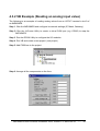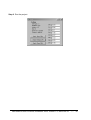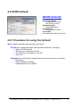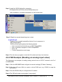
1
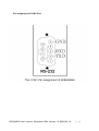
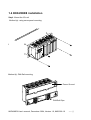
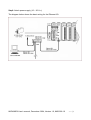
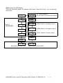
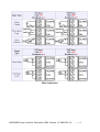
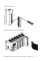
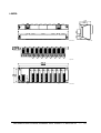
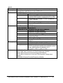
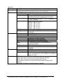
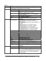
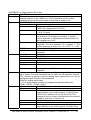
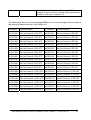
8KE4/8KE8 User’s Manual
Version 1.0, December 2004
I-8KE4-G
I-8KE8-G
ICP DAS, Co., LTD
www.icpdas.com
8KE4/8KE8 User’s manual, December 2004, Version 1.0, 8MS-002-10
----- 1
8KE4/8KE8
Warranty
All products manufactured by ICP DAS are under warranty regarding defective materials for
a period of one year, starting from the date of delivery to the original purchaser.
Warning
ICP DAS assumes no liability for damages resulting from the use of this product. ICP DAS
reserves the right to change this manual at any time without notice. The information
furnished by ICP DAS is believed to be accurate and reliable. However, no responsibility is
assumed by ICP DAS for its use, nor for any infringements of patents or other rights of third
parties resulting from its use.
Copyright
Copyright 2004 by ICP DAS. All rights are reserved.
Trademark
The names used for identification only may be registered trademarks of their respective
companies.
All information about this manual is for items as the table below.
I-8KE4-G
4-slots Ethernet I/O unit
I-8KE8-G
8-slots Ethernet I/O unit
8KE4/8KE8 User’s manual, December 2004, Version 1.0, 8MS-002-10
----- 2
Table of Contents
Chapter 1. Introduction......................................................................................................4
1.1 Features .................................................................................................................5
1.2 Specifications..........................................................................................................9
1.3 Front view of 8KE4/8KE8...................................................................................... 11
1.4 8KE4/8KE8 installation .........................................................................................13
1.5 I/O module installation ..........................................................................................16
Chapter 2. Configuring the 8KE4/8KE8 and I/O modules ..................................................20
2.1 Configure the network settings .............................................................................20
2.1.1 By “Configuration Wizard” ...........................................................................20
2.1.2 By MiniOS7 Utility........................................................................................21
2.2 Creating a virtual COM port to map the I/O modules ............................................22
2.3 Configure I/O modules..........................................................................................22
Chapter 3. Developing an application using the DCON Protocol .......................................25
3.1 The feature of using DCON Protocol ....................................................................25
3.2 Using the TCP protocol directly ............................................................................26
3.3 Via VxComm technology.......................................................................................28
Chapter 4. Software Development ToolKit (free) .............................................................29
4.1 Location of documents and software ....................................................................29
4.2 DCON Utility (DOS) ..............................................................................................31
4.2.1 Procedure for using the DCON Utility (DOS) ...............................................31
4.3 DCON DLL ...........................................................................................................32
4.3.1 Procedure for using the DLL........................................................................32
4.3.2 VB Example (Reading an analog input value) .............................................34
4.4 DCON ActiveX ......................................................................................................37
4.4.1 Procedure for using the ActiveX ..................................................................37
4.4.2 VB Example (Reading an analog input value) .............................................38
4.5 DCON Labview .....................................................................................................41
4.6 DCON Indusoft .....................................................................................................42
4.6.1 Procedure for using the Indusoft bundled driver ..........................................42
4.6.2 Indusoft Example (Reading an analog input value) .....................................42
4.7 NAP OPC Server ..................................................................................................47
4.7.1 Introduction..................................................................................................47
4.7.2 Procedure for using the OPC server............................................................48
4.7.3 OPC Server Example (Reading an analog input value)...............................49
Appendix A: Dimensions ....................................................................................................52
Appendix B: DCON protocol ..............................................................................................54
Command Set ......................................................................................................55
Hardware interface ...............................................................................................64
Appendix C: VxComm technique .......................................................................................65
Appendix D: i-8K and i-87K series I/O modules.................................................................67
Appendix E: Updating firmware and MiniOS7 image .........................................................69
E.1 Access the controller .........................................................................................70
E.2 Updating MiniOS7 image ...................................................................................73
E.3 Download firmware ............................................................................................74
8KE4/8KE8 User’s manual, December 2004, Version 1.0, 8MS-002-10
----- 3
Chapter 1.
Introduction
The i-8KE4 and i-8KE8 are Ethernet I/O units using DCON Protocol Firmware
E10M_nnn.exe (*1). ICPDAS provides various I/O modules(*2) ,using such as analog
input/output and digital input/output and counter modules which can be used in remote
data acquisition and control application for environment monitoring, power management,
factory automation, etc . via Ethernet communication.
(*1): For detail of E10M_nnn.exe, please refer to
CD:\Napdos\DCON\8KE4_8KE8\Firmware\Version_Annn.txt
ftp://ftp.icpdas.com/pub/cd/8000cd/napdos/dcon/8ke4_8ke8/firmware/
(*2): For detail of I/O modules which can be used with 8KE4 / 8KE8, please refer to
CD:\Napdos\DCON\IO_Module\
ftp://ftp.icpdas.com/pub/cd/8000cd/napdos/dcon/io_module/
8KE4/8KE8 User’s manual, December 2004, Version 1.0, 8MS-002-10
----- 4
1.1 Features
Ethernet –based Data Acquisition I/O unit
The i-8KE4 and i-8KE8 are 10Mbps Ethernet I/O unit. This feature allows Ethernet
applications to access and control the remote I/O in industrial filed network. And
E10M_nnn.exe or 8KE10.exe is the DCON firmware for the i-8430, i-8431, i-8830,
i-8831, i-8KE4 and i-8KE8. Using this firmware, applications can be easily and directly
developed using a TCP program, or via VxComm technology.
ASCII-based protocol (DCON Protocol)
The 8KE4/8KE8 control units use the DCON protocol, which is a request/reply
communication protocol used with I-7000/8000/87K series I/O modules. And is used
to access the data from the module using a simple ASCII format. For example, sending
the command “$01M” will query the controller name. The responding module will reply
with a message similar to “!018KE4(cr)”
For more details regarding the DCON Protocol, please refer to Appendix B: DCON
protocol.
For DCON Protocol about 8000 MCU and 8000 series I/O modules. Please refer to :
CD:\Napdos\DCON\IO_Module\hw_dcon_on_8KUnit
ftp://ftp.icpdas.com/pub/cd/8000cd/napdos/dcon/io_module/hw_dcon_on_8kunit/
Various SDK provided (free)
In order to access the I/O modules that are connected to 8KE4/8KE8.
Various SDKs are provided, such as: (see Note1, Note2, Note3)
z
z
z
z
z
z
DLL driver
ActiveX component
LabView bundled driver
Indusoft bundled driver
Linux driver
OPC server
Note1: All these SDKs include the DCON Command and can be easily and quickly
integrated into the user's system. Please refer to Chapter 3 for more detail information.
Note2: When applied to an Ethernet interface, users should first install VxComm utility
when using these SDKs
Note3: DLL, ActiveX, LabView, IndoSoft, OPC server and VxComm utility only support the
windows platform. (Windows 98, Windows NT, Windows 2000, Windows XP)
8KE4/8KE8 User’s manual, December 2004, Version 1.0, 8MS-002-10
----- 5
I/O configurable via the Ethernet
The DCON Utility is used to configure I-7000, I-8000 and I-87K series I/O modules. It
originally communicated with the I/O modules via the COM port. For I/O modules on the
i-8KE4 and i-8KE8, using the VxComm technique to create a virtual COM port can let
DCON Utility access the I/O modules via the Ethernet. For more details, please refer to
Chapter 3.
Simultaneous access by a maximum of 6 host PCs
Although a maximum of 6 host PCs are allowed simultaneous access, it is
recommended that fewer host PCs are used in order to give better performance and
stability.
Internet
Updateable firmware (via the RS-232 port)
Firmware
Note: the 8KE4/8KE8’s COM1 port can be used to download firmware, update the
MiniOS image file, and to configure IP.
When should the firmware be updated ?
Î Firmware should be updated when ICPDAS announces
z
z
z
Support for new I/O modules
The addition of new functions
Bug fixes and revision
8KE4/8KE8 User’s manual, December 2004, Version 1.0, 8MS-002-10
----- 6
There is a document (Revision.txt) that records the update information as follows:
For more details, please refer to Appendix E: Updating the firmware and MiniOS7 image.
Dual Bus design to supports i-8K and i-87K series I/O modules
The 8KE4/8KE8 has two types of bus on its back plane. The first is a serial bus (RS-485
interface) for 87K I/O modules and the second is a parallel bus for 8K I/O modules. The
DCON firmware can support both 8K and 87K series I/O modules. These two series I/O
modules can both be connected into the same I-8000 MCU, and can use the same
DCON command when they are both attached to I-8000 MCU. The modules for DI, DO,
DIO, AI, AO and Counter/Frequency purpose are supported. Other modules, such as
multi-serial port (8112, 8144, 8142, 8144), MMC (8073), motion (8090, 8091), are not
supported. For more details, please refer to Appendix D: i-8K and i-87K series I/O
modules.
For more about I/O module’s information, please refer to
CD:\ Napdos\DCON\IO_Module\hw_dcon_on_8KUnit
ftp://ftp.icpdas.com/pub/cd/8000cd/napdos/dcon/io_module/hw_dcon_on_8kunit/
More flexible I/O combination and Compact、fasten、quick to install
The 8KE4/8KE8 control units contain either a 4-slot or 8-slot bus to allow various i/o
modules to be connected, removing the need for complex wiring between i/o modules.
Furthermore, various I/O modules can be inserted into the slots at the same time, such
as digital input/output, analog input/output and counter modules, and each I/O module
allows various numbers of channels. For example, with i-8040 or i-8041, the 8KE8
provides max 256 digital input or digital output channels.The module can simply be
plugged into the slot and secured to the plastic base using a pair of locking buttons. The
assembly can then be mounted on the control box using DIN rail clips.
8KE4/8KE8 User’s manual, December 2004, Version 1.0, 8MS-002-10
----- 7
Built-in Watchdog
The built-in watchdog circuit will reset the CPU module if a failure occurs in either the
hardware or software. If the application program does not refresh the watchdog timer
within 1.6 sec, the watchdog circuit will initiate a reset of the CPU.
Input Protection circuitry
The protection circuitry on both the network and power supply protects the system from
external signals such as main spikes and ambient electrical noise. In addition, the
central processing module is isolated from external signals in three ways. This is
achieved through I/O isolation of 3KV, power isolation to 3KV and network isolation to
2KV
High performance integrated power supply
The built-in isolated 20W power supply is rated to perform linearly up to full loading.
Ventilated housing design to work between -25 ~+75℃
The 8KE4/8KE8 is housed in a plastic base box with a column-like ventilator, that can
help to cool the work environment inside the box and allow the 8KE4/8KE8 to operator
between -25℃ and +75℃.
8KE4/8KE8 User’s manual, December 2004, Version 1.0, 8MS-002-10
----- 8
1.2 Specifications
•
CPU:
80186-80 or compatible
16-bits
80MHz
•
SRAM:
512KBytes
•
Flash ROM:
512KBytes
8 sectors, each sector has 64KBytes
100,000 erase/write cycles
•
EEPROM:
2K bytes
8 blocks, each block has 256Bytes
1,000,000 erase/write cycles
•
NVRAM:
31 bytes
unlimited erase/write cycles
battery backup for 10 years
•
Real time clock:
seconds, minutes, hours, days, month, year
valid from 1980 to 2079
•
Built-in Watchdog Timer
0.8 seconds
•
Ethernet port:
10BaseT NE2000 compatible
PC application use Ethernet to communicate with DCON Firmware.
•
COM0 (RS-232):
TXD, RXD, GND, internal serial bus.
Fixed communication speed at 115200 bps.
Used to communicate with 87K modules connected to the slots.
•
COM1 (RS-232):
TXD, RXD, GND
Communication speed: programmable, 115200 bps max.
Used to download firmware, update the MiniOS image file and to configure the IP
information
•
SMMI (Small Man Machine Interface)
5-digit LED display
4 LED indicators
4 push buttons
•
I/O expansion slots:
4 slots for 8KE4
8 slots for 8KE8
8KE4/8KE8 User’s manual, December 2004, Version 1.0, 8MS-002-10
----- 9
•
Mounting mechanism
pannel mounting and din-rail mounting
•
Power supply:
20W
•
Power requirement:
10 ~ 30 VDC
•
Power consumption:
3.9 W (for 8KE4)
5.1 W (for 8KE8)
•
Operating Environment:
Operating Temp.: –25°C to +75°C.
Storage Temp.: –30°C to +85°C
Humidity: 5 ~ 95%,non-condensing
•
Dimension:
230 x 110 x 75.5 mm (for 8KE4)
354 x 110 x 75.5 mm (for 8KE8)
For more detailed dimensions, please refer to “Appendix A:Dimensions”.
8KE4/8KE8 User’s manual, December 2004, Version 1.0, 8MS-002-10
----- 10
1.3 Front view of 8KE4/8KE8
8KE4:
Small Man Machine Interface
Power: 10~30VDC
Initial pin
+VS
Input:
10~30VDC
GND
INIT*
Initialize
INIT*COM
Ethernet
10 BaseT
RS-232
(COM1)
10M Ethernet port
8KE8:
Slot 0
Slot 1
Slot 2
Slot 3
Small Man Machine Interface
Power: 10~30VDC
Initial pin
+VS
Inp ut:
1 0 ~ 30 V D C
GND
IN IT*
Initialize
IN IT *C O M
E th erne t
1 0 B a seT
RS-232
(COM1)
10M Ethernet port
Slot 0
Slot 2
Slot 1
Slot 4
Slot 6
Slot 3
Slot 5
Slot 7
8KE4/8KE8 User’s manual, December 2004, Version 1.0, 8MS-002-10
----- 11
Pin assignment of COM1 Port
8KE4/8KE8 User’s manual, December 2004, Version 1.0, 8MS-002-10
----- 12
1.4 8KE4/8KE8 installation
Step1: Mount the I/O unit
Method (a): using screw panel mounting
Step1 (b): Mount the I/O unit (method b: DIN-rail mounting)
Method (b): DIN-Rail mounting
Frame Ground
DIN-Rail Clips
8KE4/8KE8 User’s manual, December 2004, Version 1.0, 8MS-002-10
----- 13
Step2: Attach power supply (10 ~ 30 VDC)
The diagram below shows the basic wiring for the Ethernet I/O.
8KE4/8KE8 User’s manual, December 2004, Version 1.0, 8MS-002-10
----- 14
Step3: Check the LED display
The LED constantly shows IP address, Baud Rate, Data Bit Format ..etc as following
sequences.
1.27.00
11111.
The IP is
192.168.255.1
1.
192
2.
168
3.
255
4.
1
27: Free-sockets=27
00: No client connects to this 8000E
44444.
8.
821
COM8: data=8, odd parity, stop=1
2.
712
COM2: data=7, even parity, stop=2
1.
801
COM1: data=8, no parity, stop=1
33333.
22222.
1.
96
Baud Rate of COM1=9600
2.
96
Baud Rate of COM2=9600
8KE4/8KE8 User’s manual, December 2004, Version 1.0, 8MS-002-10
----- 15
1.5 I/O module installation
Step1: Read the document at the following location
For I-8000 series modules the files are located at:
CD:\ Napdos\DCON\IO_Module\hw_dcon_on_8KUnit\8k
ftp://ftp.icpdas.com/pub/cd/8000cd/napdos/dcon/io_module/hw_dcon_on_8kunit/8k/
For I-87K series modules the files are located at:
CD:\ Napdos\DCON\IO_Module\hw_dcon_on_8KUnit\87k
ftp://ftp.icpdas.com/pub/cd/8000cd/napdos/dcon/io_module/hw_dcon_on_8kunit/87k/
These *.chm files include the I/O module specifications, pin assignments, wire connections.
For example, the pin assignments and wire connections are as follows.
8KE4/8KE8 User’s manual, December 2004, Version 1.0, 8MS-002-10
----- 16
Pin assignment
8KE4/8KE8 User’s manual, December 2004, Version 1.0, 8MS-002-10
----- 17
Wire Connection
8KE4/8KE8 User’s manual, December 2004, Version 1.0, 8MS-002-10
----- 18
Step2: Connect the wire
Step3: Insert the I/O module into the 8KE4/8KE8
8KE4/8KE8 User’s manual, December 2004, Version 1.0, 8MS-002-10
----- 19
Chapter 2. Configuring the 8KE4/8KE8 and I/O modules
Before using the 8KE4/8KE8 and any I/O modules connected to it, the following settings
must be configured:
•
Networking settings: IP, Mask, Gateway of 8KE4/8KE8
•
Power on value of AO, DO modules
•
Safe value of AO, DO modules
•
Input range of AI modules
•
Noise filter of AI modules
•
Check sum of all communication protocol
The most important thing at the beginning stage is the network setting. After assigning the
network setting, the VxComm Utility can be used to create a virtual COM port to map the
8KE4/8KE8, and then the DCON utility can be used to configure other settings.
2.1 Configure the network settings
Network settings can only be configured via the RS-232 COM Port.
There are two tools that can be used to configure the network settings of 8KE4/8KE8. The
first is “Configuration Wizard” and the other is the MiniOS7 Utility.
2.1.1 By “Configuration Wizard”
The “Configuration Wizard” gives step by step information for configuring the network
settings. The wizard is most useful for detecting the host PCs network settings, searching
the local network to locate a valid IP, Mask and Gateway address. Using the “Configuration
Wizard”, allows automatic detection of the important settings, removing the need to contact
system administrators for support.
Step1: Use CA-0915 to connect COM1 of 8KE4/8KE8 to COM1/2 of the host PC.
Step2: Install PCDiag to the host PC by running
CD:\Napdos\7188e\tcp\PCDiag
Step3: Follow the instructions given by the “Configuration Wizard” until the following
window appears
8KE4/8KE8 User’s manual, December 2004, Version 1.0, 8MS-002-10
-----
20
3
Step4: Open the COM port and then click “Configure” to set the IP, Mask, Gateway to
8KE4/8KE8.
4.1
4.2
4.21
Step5: Exit the “Configure Wizard” and then restart the 8KE4/8KE8 for the new settings.
2.1.2 By MiniOS7 Utility
The MiniOS7 Utility is used to download files and update the OS image to the 8KE4/8KE8.
It can also be used to configure the network and COM port settings. In contrast to
“Configure Wizard”, users must have valid IP, Mask, Gateway information and must
manually enter it into the text box provided.
Step1: Use CA-0915 to connect COM1 of 8KE4/8KE8 to COM1/2 of the host PC.
Step2: Install the MiniOS7 Utility on the host PC by running
CD:\Napdos\MiniOS7\Utility\MiniOS7_Utility\MiniOS7_Utility.exe
8KE4/8KE8 User’s manual, December 2004, Version 1.0, 8MS-002-10
-----
21
Step3: Run the MiniOS7 Utility and click “Configuration”
Step4: Exit the MiniOS7 Utility and then restart the 8KE4/8KE8 for the new settings.
2.2 Creating a virtual COM port to map the I/O modules
Step1: Wire the 8KE4/8KE8 and configure its network settings (IP, Mask, Gateway)
Step2: Install the VxComm driver appropriate for your PC (95/98/NT/2000/XP)
CD:\Napdos\7188e\tcp\VxComm\Driver(PC)\
Step3: Run the VxComm Utility and connect to the 8KE4/8KE8
Step4: Map the “Port I/O” to a virtual COM port.
Step5: Exit the VxComm Utility
2.3 Configure I/O modules
The DCON Utility is used to configure I-7000, I-8000 and I-87K series I/O modules and
communicates with I/O modules via the COM port. For I/O modules on the i-8KE4 and
i-8KE8, using the VxComm technique can let DCON Utility to access the I/O modules via
the Ethernet.
DCON Utility
Main functions
Configuring modules
Baudrate
Address
Check sum
Power on value
Safe value… etc.
Testing I/O actions
Modules supported:
i-7000/i-8000/i-87K series
(with DCON protocol)
OS supported:
Windows 98/NT/2000/XP
File location:
CD:\Napdos\Driver\DCON_Utility
8KE4/8KE8 User’s manual, December 2004, Version 1.0, 8MS-002-10
-----
22
Step1: Wire the 8KE4/8KE8 and configure its network settings (IP, Mask, Gateway)
Step2: Create a virtual COM port (for example: COM3) to map the I/O modules
Step3: Install the DCON Utililty by running
CD:\Napdos\Driver\DCON_Utility\Setup\setup.exe and then run it.
3.1
4.1
4.2
4.3
8KE4/8KE8 User’s manual, December 2004, Version 1.0, 8MS-002-10
-----
23
Step4: Change the COM port to the virtual COM port. Note: for 8KE4/8KE8, the Baud Rate
is unimportant. Any Baud Rate setting can be used.
Step5: Search for the I/O modules on the 8KE4/8KE8. After the modules are found,
individually click on them to configure them.
5.1
5.2
5.3
5.4
Note
Note: All the 87K I/O modules that connected to 8KE4/8KE8 are rename to 80xx(87K)
8KE4/8KE8 User’s manual, December 2004, Version 1.0, 8MS-002-10
-----
24
Chapter 3. Using the DCON Protocol
3.1 The feature of using DCON Protocol
The DCON firmware which uses ASCII Command provided with the 8KE4/8KE8, is easy to
use and most of application can be developed using toolkits supported by ICPDAS, such as
DLL, ActivateX or OPC Server, which can shorten their development time.
8KE4/8KE8 User’s manual, December 2004, Version 1.0, 8MS-002-10
-----
25
3.2 Using the TCP protocol directly
Supports the DCON communication protocol on the Ethernet port. A TCP program can be
used to develop Ethernet Applications to communicate with Ethernet port 9999 of the
8KE4/8KE8.
The following steps show how to use VB Winsock component .
Step 1. Connect to the Ethernet controller
Step 2. Send command with cr
Step 3. Receive data from Ethernet controller
Step 4. Close connection.
8KE4/8KE8 User’s manual, December 2004, Version 1.0, 8MS-002-10
-----
26
The result will be as below.
This TCP application uses the DCON Protocol to communicate with Ethernet port 9999 of
the i-8KE4 Ethernet I/O controller .
The demo program can be found at
CD:\Napdos\8000\843x883x\TCP\Xserver\Client\Common\VB5\Client4
Or on the internet at
ftp://ftp.icpdas.com/pub/cd/8000cd/napdos/8000/843x883x/tcp/xserver/client/common/vb5/
client4/
8KE4/8KE8 User’s manual, December 2004, Version 1.0, 8MS-002-10
-----
27
3.3 Via VxComm technology
VxComm (“Virtual Communication Port”) is a technique that allows a COM Port to be
used to communicate with an ICPDAS Ethernet control unit. The Diagram below show
how to use VxComm Utility to map PC’s COM Port to 8KE4’s Ethernet I/O Port.
8KE4/8KE8 User’s manual, December 2004, Version 1.0, 8MS-002-10
-----
28
Chapter 4.
Software Development ToolKit (free)
4.1 Location of documents and software
The location of all documents and software related to the 8KE4/8KE8 are shown in the
following directory tree. The relevant file can quickly be located by referring to the tree.
CD:\Napdos\
DCON
8KE4_8KE8
Document
Firmware
8KE10.exe
OS_Image
Driver
1. DCON Utility
1. DLL driver
2. ActiveX (ocx) component
3. Labview driver
4. Indusoft driver
5. Linux driver
NapOPCSvr
MiniOS7
Utility
MiniOS7_Utility
7188E
TCP
VxComm
PCDiag
Driver(PC)
1. Configure Wizard
2. Send232
3. Send TCP
4. 7188E
Various SDKs are provided for the DCON protocol, such as DLL, ActiveX, Labview driver,
Indusoft driver, Linux driver, OPC server, etc. Each SDK also contains a number of helpful
free demo programs and documents, which can be found on the CD included in the
package, or can be downloaded from the ICP DAS web site or FTP site..
When planning the development of a system, appropriate software solutions should be
chosen to suit different situations. Following chart shows the relation between the software
solution and the SDK provided. Refer to the chart to find a solution to meet your
requirements.
8KE4/8KE8 User’s manual, December 2004, Version 1.0, 8MS-002-10
-----
29
The diagram below show the architecture of the SDK.
Note: All the above SDKs are based on VxComm technology when using an Ethernet
interface.
8KE4/8KE8 User’s manual, December 2004, Version 1.0, 8MS-002-10
-----
30
4.2 DCON Utility (DOS)
DCON Utility (DOS)
DCON Utility (DOS version)
Supported modules:
i-7000/8000/87K series
(with DCON protocol)
Supported demos:
C
Supported OS:
DOS
File location:
CD:\Napdos\Driver\DCON_DOS
4.2.1 Procedure for using the DCON Utility (DOS)
Step 1: Read the basic and important documents
Readme.txt: contains the basic and important information, including:
• What is DCON Utility (DOS)
• What files are installed on the PC
Step 2: Read manuals for how to start
DCON_DOS.pdf:
Explains how to use the DOS version utility to diagnose/configure the I/O modules
and how to use the C language to develop your first program running under DOS.
The manual explains following details:
•
•
•
•
How to include the lib to C
How to develop a program in C
Demo list
Function descriptions and usage
Step 3: Run DCON_DOS\Diag\test.exe to diagnose the I/O modules.
8KE4/8KE8 User’s manual, December 2004, Version 1.0, 8MS-002-10
-----
31
4.3 DCON DLL
DCON DLL
DLL library
Supported modules:
i-7000/8000/87K series
(with DCON protocol)
Supported demos:
VB/VC/BCB/Delphi
Supported OS:
Windows 98/NT/2K/XP
File location:
CD:\Napdos\Driver\DCON_DLL
4.3.1 Procedure for using the DLL
Step 1: Read the basic and important documents
Readme.txt: contains most basic and important information, including:
•
•
•
•
What is DCON DLL
What files are installed on the PC
The directory tree installed on the PC
Demo list
WhatsNew.txt: contains the version/reversion history information, including
• Bugs fixed
• Demos added or modified
• Updated DLL details
8KE4/8KE8 User’s manual, December 2004, Version 1.0, 8MS-002-10
-----
32
Step 2: Install the DCON DLL by executing:
CD:\Napdos\Driver\DCON_DLL\Setup\setup.exe
After installation, all related information can be found below
Step3: Read manuals for how to start
QuickStartManual.pdf:
Explains how to develop your first program using the DLL.
DCON_DLL.pdf explains the following details
•
•
•
•
How to include the DLL in VB/VC/Delphi/BCB
How to develop a program in VB/VC/Delphi/BCB
Demo list
Function descriptions and usage
FAQ.pdf:
Gives solutions to frequently asked questions.
Step 3: Run the demo programs to test the I/O module and learn the functions
8KE4/8KE8 User’s manual, December 2004, Version 1.0, 8MS-002-10
-----
33
4.3.2 VB Example (Reading an analog input value)
The following is an example of reading analog values from an I-87017 inserted in slot 0 of
an 8kE4/8KE8.
Step 1: Wire the 8KE4/8KE8 and configure its network settings (IP, Mask, Gateway)
Step 2: Run the VxComm Utility to create a virtual COM port (e.g. COM3) to map the
8KE4/8KE8
Step 3: Run the DCON Utility to configure the I/O modules
Step 4: Run VB and create a new project (.exe project)
Step 5: Add I7000.bas to the project
Step 6: Arrange all the components on the form
8KE4/8KE8 User’s manual, December 2004, Version 1.0, 8MS-002-10
-----
34
Step 7: Write the program code
VB Step 3
VB Step 1
VB Step 2
8KE4/8KE8 User’s manual, December 2004, Version 1.0, 8MS-002-10
-----
35
Step 8: Run the project.
8KE4/8KE8 User’s manual, December 2004, Version 1.0, 8MS-002-10
-----
36
4.4 DCON ActiveX
DCON ActiveX
ActiveX (ocx) component
Supported modules:
i-7000/8000/87K series
(with DCON protocol)
Supported demos:
VB/VC/BCB/Delphi
Supported OS:
Windows 98/NT/2K/XP
File location:
CD:\Napdos\Driver\DCON_ActiveX
4.4.1 Procedure for using the ActiveX
Step 1: Read most basic and important documents
Readme.txt: contains the basic and important information, including:
•
•
•
•
What is DCON ActiveX
What files are installed on the PC
The directory tree installed on the PC
Demo list
WhatsNew.txt: contains the version/reversion history information, including:
• Bugs fixed
• Demos added or modified
• Updated ActiveX (ocx) details
8KE4/8KE8 User’s manual, December 2004, Version 1.0, 8MS-002-10
-----
37
Step 2: Install the DCON ActiveX by executing:
CD:\Napdos\Driver\DCON_ActiveX\Setup\setup.exe
After installation, all related information can be found below
Step 3: Read the manuals describing how to start
InstallOCX.pdf:
Explains how to install/uninstall the ActiveX (ocx) component in
VB/VC/Delphi/BCB
DCON_ActiveX.pdf explains the following details:
•
•
•
•
How to include the ActiveX(ocx) in VB/VC/Delphi/BCB
How to develop a program in VB/VC/Delphi/BCB
Demo list
Function descriptions and usage
Step 4: Run the demo programs to test the I/O module and learn the functions
4.4.2 VB Example (Reading an analog input value)
The following is an example of reading analog values from an I-87017 inserted in slot 0 of
an 8kE4/8KE8.
Step 1: Wire the 8KE4/8KE8 and configure its network settings (IP, Mask, Gateway)
Step 2: Run the VxComm Utility to create a virtual COM port (e.g. COM3) to map the
8KE4/8KE8
Step 3: Run the DCON Utility to configure the I/O module
Step 4: Run VB and create a new project (.exe project)
8KE4/8KE8 User’s manual, December 2004, Version 1.0, 8MS-002-10
-----
38
Step 5: Add the ActiveX (ocx) component to the project
5.1
5.2
8KE4/8KE8 User’s manual, December 2004, Version 1.0, 8MS-002-10
5.3
-----
39
Step 6: Arrange all the components on the form
Step 7: Write the program code
VB Step 2
VB Step 3
VB Step 1
8KE4/8KE8 User’s manual, December 2004, Version 1.0, 8MS-002-10
-----
40
Step 8: Run the project
4.5 DCON Labview
DCON Labview
Bundled driver for Labview
Supported modules:
i-7000/8000/87K series
(with DCON protocol)
Supported OS:
Windows 98/NT/2K/XP
File location:
CD:\Napdos\Driver\DCON_Labview
8KE4/8KE8 User’s manual, December 2004, Version 1.0, 8MS-002-10
-----
41
4.6 DCON Indusoft
DCON Indusoft
Bundled driver for Indusoft
Supported Module:
i-7000/8000/87K series
(with DCON protocol)
Supported OS:
Windows 98/NT/2K/XP/CE
File location:
CD:\Napdos\Driver\DCON_Indusoft
4.6.1 Procedure for using the Indusoft bundled driver
Step 1: Read the basic and important documents
Readme.txt: contains the basic and important information, including:
• Files on the shipped CD
Reversion.txt: contains the reversion information, including
• Bugs fixed
• New modules supported
Step 2: Install the Indusoft bundled driver by executing
CD:\Napdos\Driver\DCON_Indusoft\Setup\setup.exe
Step 3: Read the manuals describing how to start
The DCON.pdf user’s manual describes how to use the Indusoft bundled driver
Step 4: Run the demo programs (ICPDriverTest.zip) to test I/O modules and learn the
functions
4.6.2 Indusoft Example (Reading an analog input value)
The following is an example of reading analog values from an I-87017 inserted in slot 0 of
an 8kE4/8KE8.
Step 1: Wire the 8KE4/8KE8 and configure its network settings (IP, Mask, Gateway)
Step 2: Run the VxComm Utility to create a virtual COM port (e.g. COM3) to map the
8KE4/8KE8
8KE4/8KE8 User’s manual, December 2004, Version 1.0, 8MS-002-10
-----
42
Step 3: Run the DCON Utility to configure the I/O modules
Step 4: Run Indusoft and create a new project
Step 5: Include the DCON driver
5.1
5.2
5.3
5.4
8KE4/8KE8 User’s manual, December 2004, Version 1.0, 8MS-002-10
-----
43
Step 6: Configure the DCON driver
6.2
6.1
8KE4/8KE8 User’s manual, December 2004, Version 1.0, 8MS-002-10
6.3
-----
44
Step7: Insert tags to connect to I/O modules
The address format is [Address : ModuleID : Slot : Channel]
7.1
7.2
Step8: Arrange all the components on the form
8KE4/8KE8 User’s manual, December 2004, Version 1.0, 8MS-002-10
-----
45
Step9: Double click the text box to assign a tag to it
9.1
9.2
Step10: Run the project
8KE4/8KE8 User’s manual, December 2004, Version 1.0, 8MS-002-10
-----
46
4.7 NAP OPC Server
NAP OPC server
OPC Server
Supported module:
i-7000/8000/87K series
(with DCON protocol)
Modbus embedded controller
ISaGRAF embedded controller
Supported OS:
Windows 98/NT/2K/XP/CE
File location:
CD:\Napdos\NapOPCSvr
4.7.1 Introduction
OPC (OLE for Process Control) is the first standard resulting from the collaboration of a
number of leading worldwide automation suppliers working in cooperation with Microsoft.
Originally based on Microsoft's OLE COM (component object model) and DCOM
(distributed component object model) technologies, the specification defined a standard set
of objects, interfaces and methods for use in process control and manufacturing automation
applications to facilitate interoperability. The COM/DCOM technologies provided the
framework for software products to be developed. There are now hundreds of OPC Data
Access servers and clients.
8KE4/8KE8 User’s manual, December 2004, Version 1.0, 8MS-002-10
-----
47
4.7.2 Procedure for using the OPC server
Step 1: Read the basic and important documents
Readme.txt: contains the basic and important information, including
• Files on the shipped CD
Reversion.txt: contains the reversion information, including
• Bugs fixed
• New modules supported
Step 2: Install the OPC server by executing
CD:\Napdos\NapOPCSvr\NapOPCServer.exe
Note: If there is an older version of Nap OPC Server installed on the PC, It must
be uninstalled before installing the new version.
Step 3: Read the manuals describing how to start
The NapOPCSvr.pdf is the user’s manual describing how to use the OPC server
8KE4/8KE8 User’s manual, December 2004, Version 1.0, 8MS-002-10
-----
48
4.7.3 OPC Server Example (Reading an analog input
value)
The following is an example of reading analog values from an I-87017 inserted in slot 0 of
an 8KE4/8KE8.
Step 1: Wire the 8KE4/8KE8 and configure its network settings (IP, Mask, Gateway)
Step 2: Run the VxComm Utility to create a virtual COM port (e.g. COM3) to map the
8KE4/8KE8
Step 3: Run the DCON Utility to configure the I/O modules
8KE4/8KE8 User’s manual, December 2004, Version 1.0, 8MS-002-10
-----
49
Step 4: Run the OPC server to search for I/O modules on COM3
4.1
4.2
4.4
4.3
8KE4/8KE8 User’s manual, December 2004, Version 1.0, 8MS-002-10
-----
50
Step 5: Save the configuration and close the OPC Server
Step 6: Run SCADA software to connect to the OPC Server
The OPC Server user’s manual lists the procedures for the following SCADA software:
•
Labview
•
National
•
WIZCON
•
iFix
•
Indusoft
•
Citect
Please refer to “Chapter 4 Connecting to the OPC Server” for more details.
8KE4/8KE8 User’s manual, December 2004, Version 1.0, 8MS-002-10
-----
51
Appendix A: Dimensions
i-8KE4 :
Back View
Side View
Top View
+VS
Input:
10~30VDC
GND
INIT*
Initialize
INIT*COM
Ethernet
10 BaseT
Front View
8KE4/8KE8 User’s manual, December 2004, Version 1.0, 8MS-002-10
-----
52
i-8KE8:
Back View
Side View
Top View
+VS
Input:
10~30VDC
GND
INIT*
Initialize
INIT*COM
Ethernet
10 BaseT
Front View
8KE4/8KE8 User’s manual, December 2004, Version 1.0, 8MS-002-10
-----
53
Appendix B: DCON protocol
The DCON protocol is a request/reply communication protocol for the I-7000/8000/87K
series I/O modules, and uses a simple ASCII format such as $AAN, $AASi6, #AAN,
#AASiCj,..., etc. The protocol format is defined as follows:
Basic Command Format
Command Format:
Leading Character
Module Address
Command
[CHKSUM]
CR
Response Format:
Leading Character
[Module Address]
[Data]
[CHKSUM]
CR
The Leading Character can include ‘@’, ‘#’, ‘$’, ‘%’, ‘~’, ‘!’
Checksum A 2-character checksum and is present when the checksum option is enabled.
Address
CR
0x00 ~ 0xFF
Carriage return (0x0D)
8KE4/8KE8 User’s manual, December 2004, Version 1.0, 8MS-002-10
-----
54
Command Set
The full DCON protocol command sets for i-8000 series’ can be found in
CD:\Napdos\DCON\IO_Module\
ftp://ftp.icpdas.com/pub/cd/8000cd/napdos/dcon/io_module/
Frequently used Command table reference:
Command
$AAM
$AAF
#AASi
#AASiCj
#AASiCj(data)
#AASi6
#AASi00(data)
# AASiBjDS
Command Description
Reads the Module Name
Reads the Firmware Version
Reads the analog input or counter / frequency values for all channels
of a specified slot
Reads the analog input or counter/frequency module data from
specified slot and the specified channel in the I-8000 unit.
Sets the analog voltage output module data from the specified slot
and channel in the I-8000 unit. The data format is in engineering units
only.
Read Digital input and output status at specified slot
Sets the multiple Digital output of a specified slot
Sets the single Digital output of a specified slot
8KE4/8KE8 User’s manual, December 2004, Version 1.0, 8MS-002-10
-----
55
#AASi
Command
Description
Syntax
#AASi
Reads the analog input or counter/frequency module data for all
channels from specified slot in the I-8000 unit.
#AASi[CHK](cr)
#
A delimiter character
AA
A 2-character HEX module address for the
specified I-8000 system ,ranging from 01 to FFh
Si
The specified slot number. i = 0 to 3 (4 slots) or
i = 0 to 7 (8 slots)
[CHK]
(cr)
Example
Note:
2-characters of checksum
Character Return(0x0D) for denote the end of
command
Valid Command
>(data)[chk](cr)
Invalid Command ?AA[CHK](cr)
Syntax error or communication error may get no response.
>
A delimiter for valid command
?
A delimiter for invalid command
AA
A 2-character HEX module address
(data)
A return string from the RTD input module in
engineering mode.
[CHK]
A 2-character checksum
(cr)
Carriage Return(0x0D) to denote the end of
response
Command
#01S3
Response
>+2.1234+2.1234 +2.1234 +2.1234 (cr)
Description
The data read from analog data input module
i-87013 (4 channels analog input module) in slot 3
of the I-8000 system at address 01h is
+2.1234+2.1234 +2.1234 +2.1234.
i-87013 Î 4-Channel RTD Analog Input Module
i-8017H Î Fast 8-Channel mV/V/mA Analog Input Module
i-87017 Î 8-Channel mV/V/mA Analog Input Module
i-87018 Î 8-Channel mV/V/mA and Thermocouple Analog Input
Module
i-8080 Î 8-Channel Counter/Frequency Module
8KE4/8KE8 User’s manual, December 2004, Version 1.0, 8MS-002-10
-----
56
#AASiCj
Command
Description
Syntax
Example
Notes:
#AASiCj
Reads the analog input or counter/frequency module data from
specified slot and the specified channel in the I-8000 unit.
#AASiCj[CHK](cr)
#
A delimiter character
AA
A 2-character HEX module address for the
specified I-8000 unit, ranging from 01 to FFh
Si
The specified slot number. i = 0 to 3 (4 slots) or
i = 0 to 7 (8 slots)
Cj
specified channel number.
i-87013 Î j = 0 to 3
i-8017H Î j = 0 to 7
i-87017 Î j = 0 to 7
i-87018 Î j = 0 to 7
i-8080
Î j = 0 to 7
[CHK]
The 2-character of Checksum
(cr)
Carriage Return(0x0D) for denote the end of the
command
Valid Command
>(data)[chk](cr)
Invalid Command ?AA[CHK](cr)
Any syntax or communication error may receive no response.
>
A delimiter for valid command
?
A delimiter for invalid command
AA
A 2-character HEX module address
(data)
A return string from RTD input module in
engineering mode.
[CHK]
A 2-character checksum
(cr)
Carriage Return (0x0D) to denote the end of the
response
Command
#01S3C0
Response
>+2.1234(cr)
Description
The data read from the analog data input module
in slot 3 and channel 0 of the I-8000 unit at address
01h is +2.1234.
i-87013 Î 4-Channel RTD Analog Input Module
i-8017H Î Fast 8-Channel mV/V/mA Analog Input Module
i-87017 Î 8-Channel mV/V/mA Analog Input Module
i-87018 Î 8-Channel mV/V/mA and Thermocouple Analog Input
Module
i-8080 Î 8-Channel Counter/Frequency Module
8KE4/8KE8 User’s manual, December 2004, Version 1.0, 8MS-002-10
-----
57
#AASiCj
Command
Description
Syntax
Example 1:
Example 2:
#AASiCj(data)
Sets the analog voltage output module data from the specified slot and
channel in the I-8000 unit. The data format is in engineering units only.
#AASiCj(data)[CHK](cr)
#
A delimiter character
AA
A 2-character HEX module address for the
specified I-8000 unit ,ranging from 01 to FFh
Si
The specified slot number. i = 0 to 3(4 slots) or
i = 0 to 7(8 slots)
Cj
The specified channel number.
i-87022 Î j = 0 to 1
i-87024 Î j = 0 to 3
i-87026 Î j = 0 to 3
i-8024
Î j = 0 to 3
(data)
A decimal value, always engineer unit
[CHK]
A 2-character checksum
(cr)
Carriage Return (0x0D) to denote the end of
command
Valid Command
> [chk](cr)
Invalid Command ?AA[CHK](cr)
Any syntax or communication error may receive no response.
>
A delimiter for valid command
?
A delimiter for invalid command
AA
A 2-character HEX module address
[CHK]
A 2-character of checksum
(cr)
Carriage Return (0x0D) to denote the end of
response
Command
#01S3C1+09.000
Response
> (cr)
Description
This example sends the positive value +9.000V to
the Analog Data output Module in slot 3 and
channel 1 of the I-8000 unit at address 01h. The
response indicates the command is valid
Command
#01S3C1-05.000
Response
> (cr)
Description
This example sends the negative value -5.000V to
the Analog Data output Module in slot 3 and
channel 1 of the I-8000 unit at address 01h. The
response indicates the command is valid
8KE4/8KE8 User’s manual, December 2004, Version 1.0, 8MS-002-10
-----
58
$AASi6
Command $AASi6
Description Read back the Digital Output module value and read the Digital Input
module value of a specified slot in the I-8000 unit.
Syntax
$AASi6[CHK](cr)
$
A delimiter character
AA
A 2-character HEX module address for the specified
I-8000 unit, ranging from 01 to FFh
Si
The specified slot number. i = 0 to 3 (4 slots) or
i = 0 to 7 (8 slots)
6
A Command to read the data
[CHK]
A 2-character checksum
(cr)
Carriage Return (0x0D) to denote the end of
command
Valid Command
!0D0E00[CHK](cr) for 8-bit DIO modules
!DD0000[CHK](cr) for 8-bit (or less than 8 bits)
DO modules
!EE0000[CHK](cr) for 8-bit (or less than 8 bits) DI
modules
!DDEE00[CHK](cr) for 16-bit DIO modules
!DDDD00[CHK](cr) for 16-bit DO modules
!EEEE00[CHK](cr) for 16-bit DI modules
!DDDDEEEE[CHK](cr) for 32-bit DIO modules
!DDDDDDDD[CHK](cr) for 32-bit DO modules
!EEEEEEEE[CHK](cr) for 32-bit DI modules
Invalid Command
?AA[CHK](cr)
Any syntax or communication error may receive no response.
!
A delimiter for valid command
?
A delimiter for invalid command
D
4-bit output value (0~Fh)
E
4-bit input value (0~Fh)
DD
8-bit output value (00~FFh)
EE
8-bit input value (00~FFh)
DDDD
16-bit output value (0000~FFFFh)
EEEE
16-bit input value (0000~FFFFh)
DDDDDDDD
32-bit output value (00000000~FFFFFFFFh)
EEEEEEEE
32 bit input value (00000000~FFFFFFFFh)
[CHK]
(cr)
Example
Command
Response
Description
A 2-character checksum
Carriage Return (0x0D) to denote the end of
response
$01S16
!0155AA00
The example reads the digital I/O module value from
slot 1 of the I-8000 unit at address 01h. The second
2-character value 55h (01010101) indicate the I/O
module channels 1,3,5,7 are ON and channels
0,2,4,6 are OFF.
8KE4/8KE8 User’s manual, December 2004, Version 1.0, 8MS-002-10
-----
59
# AASi00(data) For multiple channels DO output
#AASi00(data)
Command
Description Sends the value to the digital output module for multiple channels output of
a specified slot in the I-8000 unit
#AASi00(data)[CHK](cr)
Syntax
$
A delimiter character
AA
A 2-character HEX module address for the specified
I-8000 unit ,ranging from 01 to FFh
Si
The specified slot number. i = 0 to 3(4 slots) or
i = 0 to 7(8 slots)
00
00 that for multiple channels’ DO output
(data)
A 2-character or 4-character HEX for digital output
value.
For output from all channels, the data will be
2-character HEX for channel count is less than or
equal to 8 bits, 4-character for channel count is 16 bits
and greater than 8 bits. The data bit is corresponds to
the output module channel.
[CHK]
2-characters of Checksum
(cr)
Carriage Return (0x0D) to denote the end of the
command
Valid Command
>[chk](cr)
Invalid Command ?AA[CHK](cr)
Any syntax or communication error may receive no response.
>
A delimiter for valid command
?
A delimiter for invalid command
[CHK]
A 2-character of checksum
(cr)
Note
Example
Carriage Return (0x0D) to denote the end of the
response
If any channel of digital output module (*1) is configured for an analog
input alarms then this command has no effect on the specified channel.
The channel is always used for analog input alarms and can not be
configured again unless it is disconnected.
Refer to: Analog Input Alarm
(*1) For digital output modules not support analog input alarm are :
i-8041, i-87041, i-87042, i-8050
Command
#01S30042
Response
>(cr)
Description
This example is for an 8-channel digital output
module. The Digital output Module in slot 3 and
channel 2 and channel 6 of the I-8000 unit at address
01h will be set to ON. This example is only for output
modules where the channel number is less than or
equal to 8.
Command
#01S300AA55(cr)
Response
>(cr)
Description
This example is for a 16-channel digital output
8KE4/8KE8 User’s manual, December 2004, Version 1.0, 8MS-002-10
-----
60
module. The Digital output Module in slot 3 and
channels 0,2,4,6 (55h), 9, 11, 13, 15 (AAh) of the
I-8000 unit at address 01h will be set to ON. Channels
1, 3, 5, 7, 8, 10, 12, 14 are set to OFF. This example
just for output module channel number is greater than
8 and less then or equal to 16.
8KE4/8KE8 User’s manual, December 2004, Version 1.0, 8MS-002-10
-----
61
# AASiBjDS For single channel DO output
#AASiBjDs
Command
Description This command sends the value to the digital output module of the specified
channel and slot of the I-8000 unit. This command is only for output
modules which the channel number is less than or equal to 16.
#AASi1BDs[CHK](cr)
Syntax
$
A delimiter character
AA
A 2-character HEX module address for the specified
I-8000 unit ,ranging from 01 to FFh
Si
The specified slot number. i = 0 to 3(4 slots) or
i = 0 to 7(8 slots)
Bj
The channel to be set will contain two characters.The
first character ‘B’ is always be number 1, and the
second character ‘j’ indicates the channel will be set
and ranging from 0 to F.
Ds
For single channel output the data will contain two
character. The first character ‘D’ is always 0. The
second character is ether 0 or 1. 0 => OFF, 1 => ON.
[CHK]
2-characters of Checksum
(cr)
Carriage Return (0x0D) to denote the end of the
command
Valid Command
>[chk](cr)
Invalid Command ?AA[CHK](cr)
Any syntax or communication error may receive no response.
>
A delimiter for valid command
?
A delimiter for invalid command
[CHK]
A 2-character of checksum
(cr)
Note
Example
Carriage Return (0x0D) to denote the end of the
response
If any channel of digital output module (*1) is configured for an analog
input alarms then this command has no effect on the specified channel.
The channel is always used for analog input alarms and can not be
configured again unless it is disconnected.
Refer to: Analog Input Alarm
(*1) For digital output modules not support analog input alarm are :
i-8041, i-87041, i-87042, i-8050
Command
#01S31C01
Response
>(cr)
Description
This example is for a single channel. The Digital
output Module in slot 3 and channel 12 (0Ch) of the
I-8000 unit at address 01h will be set to ON. This
example is only for output modules which the channel
number is less than or equal to 16.
Command
#01S31A00(cr)
Response
>(cr)
Description
This example is for a single channel. The Digital
output Module in slot 3 and channel 10 (0Ah) of the
8KE4/8KE8 User’s manual, December 2004, Version 1.0, 8MS-002-10
-----
62
I-8000 unit at address 01h will be set to OFF. This
example is only for output modules where the channel
number is less than or equal to 16.
The table below show to use command #AASiBjs to set 16-channel digital output module of
the specified channel and slot of the I-8000 unit.
Command
Channel Status
Command
Channel Status
#01S31000
Set the Channel 0 DO OFF
#01S31001
Set the Channel 0 DO ON
#01S31100
Set the Channel 1 DO OFF
#01S31101
Set the Channel 1 DO ON
#01S31200
Set the Channel 2 DO OFF
#01S31201
Set the Channel 2 DO ON
#01S31300
Set the Channel 3 DO OFF
#01S31301
Set the Channel 3 DO ON
#01S31400
Set the Channel 4 DO OFF
#01S31401
Set the Channel 4 DO ON
#01S31500
Set the Channel 5 DO OFF
#01S31501
Set the Channel 5 DO ON
#01S31600
Set the Channel 6 DO OFF
#01S31601
Set the Channel 6 DO ON
#01S31700
Set the Channel 7 DO OFF
#01S31701
Set the Channel 7 DO ON
#01S31800
Set the Channel 8 DO OFF
#01S31801
Set the Channel 8 DO ON
#01S31900
Set the Channel 9 DO OFF
#01S31901
Set the Channel 9 DO ON
#01S31A00
Set the Channel 10 DO OFF
#01S31A01
Set the Channel 10 DO ON
#01S31B00
Set the Channel 11 DO OFF
#01S31B01
Set the Channel 11 DO ON
#01S31C00
Set the Channel 12 DO OFF
#01S31C01
Set the Channel 12 DO ON
#01S31D00
Set the Channel 13 DO OFF
#01S31D01
Set the Channel 13 DO ON
#01S31E00
Set the Channel 14 DO OFF
#01S31E01
Set the Channel 14 DO ON
#01S31F00
Set the Channel 15 DO OFF
#01S31F01
Set the Channel 15 DO ON
8KE4/8KE8 User’s manual, December 2004, Version 1.0, 8MS-002-10
-----
63
Hardware interface
The hardware interface used to access the I-7000/8000/87K series I/O modules can be
divided into the following:
z
RS-232: I-8000 MCU with R232_nnn.exe (or 8K232.exe) firmware.
Baud Rate: 1200, 2400, 4800, 9600, 19200, 38400, 57600, 115200bps.
Data format is: 1 start bit, 8 data bits, non-parity, 1 stop bit
z
RS-485: I-7000/87K series I/O modules and I-8000 MCU with R485_nnn.exe (or
8K485.exe ) firmware
Baud Rate: 1200, 2400, 4800, 9600, 19200, 38400, 57600, 115200bps.
Data format is: 1 start bit, 8 data bits, non-parity, 1 stop bit
z
Ethernet: I-8000E MCU with E10M_nnn.exe (or 8KE10.exe) firmware
Speed: 10Mbps
Even though the I-7000/87K series I/O modules are not equipped with an Ethernet interface,
by using the I-7188E/8000E in connection with the VxComm technique, they can still be
accessed via the Ethernet.
Note:
1.
I-8000 MCU includes 8410, 8411, 8810, 8811, 8430,8431, 8830, 8831, 8KE4, 8KE8.
2.
8000E means an I-8000 MCU equipped with an Ethernet port, such as 8430, 8431,
8830, 8831, 8KE4, 8KE8.
3.
Both the I-8000 and I-87K series I/O modules can be inserted into the I-8000 MCU
simultaneously.
4.
When the I-87K series I/O module is inserted into the I-8000 MCU, it uses the same
commands as the I-8000 series I/O modules .
5.
The 87K series expansion unit series includes 87K4, 87K5, 87K8, 87K9.
6.
The I-87K series I/O modules use different commands when they are inserted into the
I-8000 MCU and the I-87K expansion unit.
8KE4/8KE8 User’s manual, December 2004, Version 1.0, 8MS-002-10
-----
64
Appendix C: VxComm technique
VxComm (“Virtual Communication Port”) is a technique that allows access to remote I/O
slots or RS-232 ports. There are two types of software interfaces that can be used to
access remote I/O modules and the COM ports of the 7188E/8000E series the first is serial
port interface and the second is the TCP/IP interface. For the serial port interface, we
provide a VxComm driver for Windows OS. It is used to create virtual COM ports to map to
I/O modules and COM ports of the 7188E and 8000E. After creating virtual COM ports, you
can easily upgrade serial devices to with Ethernet communication ability and the original
software only need to link to a virtual COM port. It doesn’t need any source code
modification.
Comparison of using Virtual COM Port and TCP Port
Use Virtual COM Port interface
to develop Ethernet application.
Use TCP Port interface
Programming
method
Program has to Send and Program has to Send and
Receive command via COM Port receive command via TCP Port
Extra Driver
Need to install VxComm driver on No
PC
Platform
Windows 98 /NT /2000 /XP
SDK provided
DLL, ActiveX, LabView bundle No ,program has to use DCON
directly
to
driver, InduSoft bundle driver, Protocol
communicate with I/O modlues
OPC driver
All platforms
8KE4/8KE8 User’s manual, December 2004, Version 1.0, 8MS-002-10
-----
65
The two application architectures are shown as below:
8KE4/8KE8 User’s manual, December 2004, Version 1.0, 8MS-002-10
-----
66
Appendix D: i-8K and i-87K series I/O modules
The DCON firmware (8K232.exe, 8K485.exe and 8KE10.exe) supports both 8K and 87K
series I/O modules. The two series I/O modules can be plug in same I-8000 MCU. The
modules for DI, DO, DIO, AI, AO and Counter/Frequency purpose are supported. Other
modules such as multi-serial port (8112, 8144, 8142, 8144), MMC(8073), motion (8090,
8091) are not supported. The file in the shipped CD lists details.
CD:\Napdos\Driver\DCON_Utility\DCON_Utility_Module_List.htm
The DCON firmware only accepts 4 digits numbers. Thus both 8K and 87K series are
recognized as 4 digits numbers. When using the DCON Utility to search I/O modules, the
screen shown as following:
8KE4/8KE8 User’s manual, December 2004, Version 1.0, 8MS-002-10
-----
67
The differences between I-8000 and I-87K series I/O modules are
Item
i-8000 series
Microprocessor
No
Communication interface
Parallel bus (Note1)
Communication speed
Fast
DI latched function
No
Counter input (for digital input module)
No
Power on value
Yes (Note3)
Safe value
Yes (Note3)
Host watchdog
Yes
Module watchdog
No
Programmable slew-rate for AO module
No
i-87K series
Yes (8051)
Serial bus (Note2)
Slow
Yes
Yes (100 Hz)
Yes
Yes
Yes
Yes
Yes
Note:
1.
The 8000 series and 87K I/O modules can both be connected into the same i-8000
MCU, for there are two types of buses on i-8000 series main-board. Through the
parallel bus, the CPU can communicate with I/O modules very fast. For digital I/O
modules, the communication time takes less than 0.012 ms. For analog I/O modules, it
depends on the modules. For example, I-8017H’s scan rate is 50K samples per
second and I-8024’s throughput is 2100 samples per second.
2.
Through the serial bus (RS-485), the communication speed is 115200 bps Maximum.
The communication time depends on the command and response length (bytes).
Normally, for digital I/O modules, one module takes less then 1 ms; for analog I/O
modules, one sample takes less than 2 ms.
3.
The hardware design of the I-8000 series I/O modules doesn’t have the power on
value and safe value. Running the DCON firmware on the I-8000 MCU, they can have
the functions.
8KE4/8KE8 User’s manual, December 2004, Version 1.0, 8MS-002-10
-----
68
Appendix E: Updating firmware and MiniOS7 image
In following situations, we release the new version firmware and MiniOS7 image.
z
z
z
Supporting new I/O modules
Adding new functions
Fixing bugs
The tool to update firmware and MiniOS7 image is MiniOS7 Utility.
File location of MiniOS7 Utility
CD:\Napdos\MiniOS7\Utility\MiniOS7_Utility\MiniOS7_Utility.exe or
ftp://ftp.icpdas.com/pub/cd/8000cd/napdos/minios7/utility/minios7_utility/
8KE4/8KE8 User’s manual, December 2004, Version 1.0, 8MS-002-10
-----
69
E.1
Access the controller
Please follow the steps to do the updating procedure.
Step1: Install MiniOS7 Utility
Step2: Use CA-0915 to connect 8KE4/8KE8 to COM1/2 of the host PC.
Step3: Short Init* and Init*COM.
Step4: Power off and then power on the 8KE4/8KE8. The CPU doesn’t run the
autoexec.bat while power on stage.
841X/881X
4
3
POWER SUPPLY
Power: 10~
+10V~30VDC
30 VDC
2
RS-232
DEVICE
CA0915
CA-0915
8KE4/8KE8 User’s manual, December 2004, Version 1.0, 8MS-002-10
-----
70
Step5: Run MiniOS7 Utility
Step6: Select the COM port of the host PC.
6.1
6.2
8KE4/8KE8 User’s manual, December 2004, Version 1.0, 8MS-002-10
-----
71
After opening the COM port, the MiniOS7 Utility will show informations as below:
i.
MiniOS7 image version of the 8KE4/8KE8.
ii.
Files in the Flash ROM
2. List files in the
Flash ROM
1. MiniOS7 image
information
8KE4/8KE8 User’s manual, December 2004, Version 1.0, 8MS-002-10
-----
72
E.2
Updating MiniOS7 image
After setup MiniOS7 Utility and initial the 8KE4/8KE8. please follow the steps to do
the updating MiniOS7 image.
Step1: Click
and select the file to update MiniOS7.
(File : CD:\Napdos\DCON\8KE4_8KE8\OS_Image\8e040420.img)
ftp://ftp.icpdas.com.tw/pub/cd/8000cd/napdos/dcon/8ke4_8ke8/os_image/8e040420.img
1.1
8KE4/8KE8 User’s manual, December 2004, Version 1.0, 8MS-002-10
-----
73
E.3
Download firmware
Please follow the steps to download the firmware to the Flash ROM.
Step1: Delete all files in the Flash ROM.
Step2: Select the firmware files and autoexec.bat and click
files into the Flash ROM
to download the
1
2.1
2.2
Step3: Disconnect Init* and Init*COM
4
3
Step4: Run the firmware
Method 1: Power off and then power on the 8KE4/8KE8. The CPU will run
the autoexec.bat in the Flash ROM.
Method 2: Click
to run the firmware.
8KE4/8KE8 User’s manual, December 2004, Version 1.0, 8MS-002-10
-----
74