1
Instruction Manual
Analyser Reference System
Type ARS 16/1
Serial No.:
UO467 07/0 0613
The manufacturer can not be held liable for incorrect statements and their consequences; subject to change !
Instruction Manual
Analyser Reference System
Type ARS 16/1
Serial No.:
A5093 07/0 0413
The manufacturer can not be held liable for incorrect statements and their consequences; subject to change !
User Manual Analyser Reference System
1. General Instructions
2. Connection
3. Safety
4. Analyser Reference System ARS 16
4.1. Front Panel
4.2. Rear Panel
4.3. Description
4.3.1. Operation
4.3.2. Status
4.3.3. Operation Mode
4.3.4. Phase
4.3.5. Range
4.3.6. Measuring Outputs
4.3.7. Sense Lines
4.3.8. Current Ranges
4.3.9. Error Messages
4.3.10. External Inputs
4.3.11. Block Diagram
4.4. Interface
4.4.1. IEEE 488
4.4.2. Command Syntax
4.4.3. List of Commands
4.4.4. IMPEDANCE
4.4.5. SET_IMPEDANCE
4.4.6. H_I_RANGE
4.4.7. PHASE
4.4.8. *IDN? (only query)
4.5. Technical Data
4.6. Technical Information
4.6.1. Pin Assignment
3
3
4
5
5
6
7
7
7
8
8
8
9
9
9
9
10
10
11
11
12
13
14
15
16
17
18
19
20
20
23.04.2013 HE_ARS16_0413.doc
Spitzenberger & Spies GmbH & Co. KG
Page 1
User Manual Analyser Reference System
23.04.2013 HE_ARS16_0413.doc
Spitzenberger & Spies GmbH & Co. KG
Page 2
User Manual Analyser Reference System
1. General Instructions
This device has been shipped in perfect safety condition. However, it has to be checked
for mechanical defects before the first start-up. If there is any transportation damage the
device must not be put into operation. Spitzenberger & Spies has to be informed
immediately.
Important Reference: The devices/racks must only be moved/transported in
upright position! Exceptions are only permissible after
consultation with the manufacturer! The customer is liable
for defects caused by disregarding this regulation.
2. Connection
Before connecting the device please make sure that the line voltage and frequency
correspond with the device’s. Note that the protected earthing conductor has to be
connected according to regulations. The earthing resistance has to meet the relevant
safety regulations. Insufficient connection of the protected earthing conductor might
cause malfunctions of the system. We recommend to supply the system via fault-current
circuit breaker.
Mains voltage
Mains frequency
Mains protection
Releasing characteristics (recommended)
Fault-current circuit breaker ( recommended)
Mains plug
230V (+6% -10%)
50Hz/60Hz
2A
C or D
≥ 30mA
Earthing contact socket 16A
When controlling the system via PC the latter should be supplied by a common mains.
To make sure that the device works faultlessly and no overheating occurs, sufficient
ventilation and enough distance from the device’s rear side to any wall has to be
guaranteed (60cm recommended).
23.04.2013 HE_ARS16_0413.doc
Spitzenberger & Spies GmbH & Co. KG
Page 3
User Manual Analyser Reference System
3. Safety
The device must only be operated by instructed personnel !
Energized parts might be uncovered when opening the housing. Before opening the
device the mains input cable has to be disconnected from the supply voltage due to
safety regulations. The chassis ground of the device is connected to earth.
Warning: Capacitors still can be charged even when the device is disconnected
from all voltage sources.
Keep a three-minute waiting period before opening the device after
having disconnected the device from each voltage sources (power
supplies).
The device output is not electrically isolated from the mains. There is
no protection by electrical separation according to the relevant VDE
regulations.
23.04.2013 HE_ARS16_0413.doc
Spitzenberger & Spies GmbH & Co. KG
Page 4
User Manual Analyser Reference System
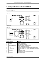
4. Analyser Reference System ARS 16
4.1. Front Panel
ARS 16/1
ARS 16/3
Pos. Lettering
Function
1
2
3
POWER
4
4
L1, N
L1, L2, L3, N
5
6
7
OUTPUT
Switch „POWER ON“
State indication via LED
Measuring outputs „Analog Output“
(Flicker / Harmonics Analyser)
Measuring output L1 for monitoring the output voltage
Measuring output L1…L3 for monitoring the output
voltage
Single phase output
Circuit breaker (16A) overload protection
Three-phase output
MEASUREMENT
OUTPUT
23.04.2013 HE_ARS16_0413.doc
Spitzenberger & Spies GmbH & Co. KG
Page 5
User Manual Analyser Reference System
4.2. Rear Panel
ARS 16/1
ARS 16/3
Pos. Lettering
Function
8
9
LINE~
FLI CH1
10
10
11
12
FLI CH2
HAR
INPUT L1
INPUT L1,L2,L3
CONTROL
IEEE 488
Mains plug with fuse (T2A)
Measurement input: Flickermeter channel 1 / voltage
harmonics analyser
Measurement input: Flickermeter channel 2
Measurement input: Harmonics current
Power connection to the voltage source (single phase)
Power connection to the voltage source (three phase)
Control: Additional impedance
Remote control: IEEE-BUS
23.04.2013 HE_ARS16_0413.doc
Spitzenberger & Spies GmbH & Co. KG
Page 6
User Manual Analyser Reference System
4.3. Description
The „Analyser Reference System“ (in the following referred to as „ARS“) contains the
standard impedance according to IEC 725 as well as a phase- and current range
switching. Combined with an analyser (Boconsult B10), it enables harmonic
measurements according to EN 61000-3-2 and flicker measurements according to
EN 61000-3-3.
To ensure fast and reasonable operation with the test system, flicker and harmonic
measurements can be performed automatically one after another with the SPS-testing
software. Thereby, the standard impedance switches uninterrupted between both
measurement modes. In addition, the current ranges of the harmonic measurement are
switched overlapping.
4.3.1. Operation
The ARS can only be controlled via IEEE-Bus.
The IEEE address is factory-adjusted:
3
Reference: This line impedance has been developed especially for the operation with an
amplifier of the PAS-series. This type of amplifier is able to supply output
voltages that could cause a damage of the line impedance (e.g. DC-voltage).
4.3.2. Status
The present measurement status is displayed at the LED’s „State“:
LED
Error
R-Control
Overload
PLL
No Sig. CH1
No Sig. CH2
Autorange
Extern
Meaning
see chapter „Error Messages“
Indicates traffic via IEEE-bus
Current measuring range is exceeded
PLL for the harmonic measurement engaged
No voltage at measurement input CH1
No voltage at measurement input CH2
Automatic range selection
The rear inputs are used for the measurements
23.04.2013 HE_ARS16_0413.doc
Spitzenberger & Spies GmbH & Co. KG
Page 7
User Manual Analyser Reference System
4.3.3. Operation Mode
The present operation mode is displayed at the LED’s „Mode“:
LED
Direct
Flicker
Harmonics
Harmonics+Imp
Meaning
The input of the ARS is switched directly to the output.
The impedance is switched between input and output. ⇒ Flicker
measurement according to EN 61000-3-3
Impedance short-circuited; the current of the selected phase flows
over the current measurement.
⇒ harmonic measurement according to EN 61000-3-2
Harmonic measurement inclusive impedance
(e.g. for the Japanese market)
4.3.4. Phase
The present measurement phase is displayed at the LED’s „Phase“:
LED
L1
L2
L3
N
Meaning
Voltage measurement between L1 and N
Voltage measurement between L2 and N
Voltage measurement between L3 and N
Voltage measurement between L1 and N, current measurement in
neutral conductor (only at harmonic measurement)
With single-phase ARS measurement is only possible between L1 and N. Phase
switching via IEEE 488 interface are not executed.
Additionally to the voltage measurement the selected phase is switched to the analyser
(B10) at operation mode „HARMONICS“.
4.3.5. Range
The selected current range for the harmonic measurement is displayed at the LED’s
„Range“.
LED
0.16A
0.8A
4A
20A
80A
250A
Meaning
Range 0.16A
Range 0.8A
Range 4A
Range 20A
Range 80A (only possible in connection with internal impedance)
Range 250A (only possible in connection with internal impedance)
23.04.2013 HE_ARS16_0413.doc
Spitzenberger & Spies GmbH & Co. KG
Page 8
User Manual Analyser Reference System
4.3.6. Measuring Outputs
The output voltage can be measured at the measuring outputs „N, L1, L2 ,L3“ at the
front panel of the ARS. The measurement outputs are protected against short-circuit
with cold resistance.
The internal resistance is approx. 100Ω.
At the front panel of the ARS there are also the measurement outputs „A“ and „B“ for
the phases L1, L2 and L3. At these outputs are analogue outputs which can be
programmed with various functions.
4.3.7. Sense Lines
The ARS is provided with a sense line for each phase. By means of these lines the
contacts and supply conductor resistors of the voltage source (e.g. amplifier type PAS)
to the line impedance are compensated.
4.3.8. Current Ranges
The current ranges for the harmonic measurement are protected against overload.
Generally, each phase of the line impedance is protected with the 16A-fuse.
4.3.9. Error Messages
Various error messages are indicated with the LED „ERROR“.
LED
Flashes in 1sec cycle
⎡⎤_⎡⎤_⎡⎤_⎡⎤_⎡⎤_⎡⎤_⎡⎤
2xflash - pause
⎡⎤_⎡⎤____⎡⎤_⎡⎤____
3xflash - pause
⎡⎤_⎡⎤_⎡⎤____⎡⎤_⎡⎤_⎡⎤
Error
Internal address error at the I2C-Bus.
ARS gets locked and can only be re-activated by means of
switching off or on.
Wrong command.
An inadmissible command has been selected via the remote
control (e.g. current range).
Internal communication error at the I2C-Bus.
ARS gets locked and can only be re-activated by means of
switching off or on.
23.04.2013 HE_ARS16_0413.doc
Spitzenberger & Spies GmbH & Co. KG
Page 9
User Manual Analyser Reference System
4.3.10. External Inputs
Via the measurement inputs „FLI CH1“, „FLI CH2“ and „HAR I“ at the rear of the
ARS, an external measuring signal (e.g. from a further line impedance) can be supplied
to the analyser unit of the ARS.
Via a specific command the ARS can be connected to the external measurement mode
(LED „Extern“ lights).
FLI CH1
Measurement input for the voltage of the test specimen (Flicker /
harmonics)
FLI CH2
Measurement input for the source voltage (Flicker)
HAR I
Measurement input for the current of the test specimen (harmonics)
3Vrms correspond to the upper limit of the current range
Electrical specifications of the inputs see chapter „Technical Data“.
4.3.11. Block Diagram
RA = 0.24Ω
RN = 0.16Ω
jXA = 0.15Ω at 50Hz
jXN = 0.10Ω at 50Hz
23.04.2013 HE_ARS16_0413.doc
Spitzenberger & Spies GmbH & Co. KG
Page 10
User Manual Analyser Reference System
4.4. Interface
4.4.1. IEEE 488
This section describes the installation of the IEEE module. IEEE 488 is a parallel 8 bit
communication standard that enables the communication of the device with an external
controller e.g. a computer or a terminal.
To each device a single IEEE address is assigned. The application of one address for
two devices is not allowed.
The IEEE address is set to 3.
23.04.2013 HE_ARS16_0413.doc
Spitzenberger & Spies GmbH & Co. KG
Page 11
User Manual Analyser Reference System
4.4.2. Command Syntax
The basic structure of a command is made up of the elements command, equal sign and
argument. The commands are case insensitive.
Example: SET:IMPEDANCE=ON
SET:IMPEDANCE is the command, on is the argument. An equal sign has to be set
between command and argument.
The capital letters of the command must be input, the lower case letters are optional.
Only single commands can be transferred.
The basic structure of a query is made up of a command (possibly also equal sign and
argument) and a question mark.
Example: SET:IMPEDANCE?
When using IEEE interface the return value is available for transmission in an output
puffer.
The device has a maximum input puffer with 256 characters. In this input puffer the
transferred characters are stored until the command is executed. If more than 256
characters are fed the following characters are rejected until memory is available.
Default in on-position:
IMPEDANCE=L, SET_IMPEDANCE=OFF, H_I_RANGE=3 und PHASE=0.
Adjustments for
Direct-Mode:
Flicker-Mode:
Harmonics-Mode:
Harmonics+Imp-Mode:
H_I_RANGE=8,
H_I_RANGE=8,
H_I_RANGE={1|2|3|4|5|6},
H_I_RANGE={1|2|3|4|5|6},
SET_IMPEDANCE=OFF
SET_IMPEDANCE=ON
SET_IMPEDANCE=OFF
SET_IMPEDANCE=ON
In the following section all commands and queries for the device are listed.
The following notation is used for the description of the command syntax:
Symbol
<>
{}
[]
|
...
Meaning
Defined element
Group, one element is required
Optional, can be omitted
Exclusive Or
Previous element(s) may be repeated
Examples:
H_I_RANGE=<INT>
IMPEDANCE={L|H}
23.04.2013 HE_ARS16_0413.doc
Spitzenberger & Spies GmbH & Co. KG
Page 12
User Manual Analyser Reference System
4.4.3. List of Commands
Impedance:
Description
Adjustment power arm
Impedance on/off
Adjustment current measurement range
Adjustment phases
Command
IMPEDANCE
SET_IMPEDANCE
H_I_RANGE
PHASE
Section
4.4.4
4.4.5
4.4.6
4.4.7
Command
*IDN?
Section
4.4.8
Interface:
Description
Query identification of the device
23.04.2013 HE_ARS16_0413.doc
Spitzenberger & Spies GmbH & Co. KG
Page 13
User Manual Analyser Reference System
4.4.4. IMPEDANCE
With this command the power arm can be adjusted. You can select between power flow
via ARS or via AIP.
Default
IMPEDANCE=L
Group
Impedance
Syntax
IMPEDANCE={L|H}
IMPEDANCE?
Arguments
L
Power flow via ARS
H
Power flow via AIP
Examples
IMPEDANCE=L
Selects power flow via ARS.
IMPEDANCE?
States whether the power flow
is adjusted for ARS
{IMPEDANCE=L} or AIP
{IMPEDANCE=H}.
23.04.2013 HE_ARS16_0413.doc
Spitzenberger & Spies GmbH & Co. KG
Page 14
User Manual Analyser Reference System
4.4.5. SET_IMPEDANCE
With this command the adjusted impedance can be switched on and/or off.
Default
SET_IMPEDANCE=OFF
Group
Impedance
Syntax
SET_IMPEDANCE={ON|OFF}
SET_IMPEDANCE?
Arguments
ON
Switching on the adjusted impedance
OFF
Switching off the adjusted impedance
Examples
SET_IMPEDANCE=ON
Switches on the adjusted
impedance.
SET_IMPEDANCE?
States whether the impedance
is switched on
{SET_IMPEDANCE=ON} or off
{SET_IMPEDANCE=OFF}.
23.04.2013 HE_ARS16_0413.doc
Spitzenberger & Spies GmbH & Co. KG
Page 15
User Manual Analyser Reference System
4.4.6. H_I_RANGE
With this command the current measurement range can be adjusted.
Default
H_I_RANGE=3
Group
Impedance
Syntax
H_I_RANGE={1|2|3|4|5|6|8}
H_I_RANGE?
Arguments
1
250A measuring range (AIP required, optional)
2
80A measuring range (AIP required, optional)
3
20A measuring range
4
4A measuring range
5
0.8A measuring range
6
0.16A measuring range
7
reserved (not implemented)
8
Switching off shunt
Examples
H_I_RANGE=6
Selects the 0.16A current
measurement range.
H_I_RANGE?
States which current
measurement range is selected
{H_I_RANGE=1 S4 | H_I_RANGE=2
S4 | H_I_RANGE=3 S4 |
H_I_RANGE=4 S4 | H_I_RANGE=5
S4 | H_I_RANGE=6 S4 |
H_I_RANGE=8 S4}.
Reference: The annex S4 means shunt type 4 (internal relevance).
23.04.2013 HE_ARS16_0413.doc
Spitzenberger & Spies GmbH & Co. KG
Page 16
User Manual Analyser Reference System
4.4.7. PHASE
With this command the measurement phase(s) can be adjusted. The measurement
phase(s) is/are that phase(s) where voltage and/or current is/are measured.
Default
PHASE=0
Group
Impedance
Syntax
PHASE={0|1|2|3}
PHASE?
Arguments
ARS16/x:
0
Select N for measurement phase
1
Select L1 for measurement phase
2
Select L2 for measurement phase
3
Select L3 for measurement phase
ARS16/3/TPM:
0
Select N for measurement phase
1
Select L1 for measurement phase
2
Select L1 L2 and N for measurement phase
(from Firmware: Axx24T_32.HEX)
3
Select L1 L2 and L3 for measurement phase
Examples
PHASE=1
Selects L1 for measurement
phase.
PHASE?
Returns the selected
measurement phase(s).
23.04.2013 HE_ARS16_0413.doc
Spitzenberger & Spies GmbH & Co. KG
Page 17
User Manual Analyser Reference System
4.4.8. *IDN? (only query)
With this command the identification of the device (device type, version number)can be
queried.
Group
Interface
Syntax
*IDN?
Return
<STRING> The string returns the identification of the device.
23.04.2013 HE_ARS16_0413.doc
Spitzenberger & Spies GmbH & Co. KG
Page 18
User Manual Analyser Reference System
4.5. Technical Data
Input voltage:
Harmonic:
AC:
DC:
90V ... 300V
0V ... 48V (1)
Flicker:
AC:
DC:
40V ... 504V (auto ranging)
0V ... 48V (1)
Input frequency:
45Hz … 65Hz
Continuous current:
16Arms
Short time current:
max. 32Arms
Internal resistance:
Phase conductor R + jX = (0.24Ω+j0.15Ω) at 50Hz
Neutral conductor R + jX = (0.16Ω+j0.10Ω) at 50Hz
Phase-neutral conductor R + jX = (0.40Ω+j0.25Ω) at 50Hz
Measurement accuracy:
annual calibration cycle
Harmonics measurement:
Fundamental U:
0,2% of measured value
Fundamental I:
0,2% of measured value plus
Harmonic:
Measuring range 20A
Measuring range 4A
Measuring range 0,8A
Measuring range 0.16A
±8,0mA
±1,6mA
±0,32mA
±0,20mA
Flicker measurement:
Pst:
±5% relating to Pst = 1
d-values:
0,2% Un
Additional
measuring inputs:
FLI CH1
FLI CH2
HAR I
Mains supply:
230Vrms (+6% -10%) 50/60Hz, 2A
Ambient temperature:
0°C up to +40°C
Housing:
19“-plug-in unit (4U), colour light grey (RAL7035)
approx. H=178mm; W=483mm; D=450mm
Weight:
approx. 21kg
0Vac ... 300Vac
0Vac … 300Vac
0Vp … 10Vp (2)
(1)
At DC-voltages >48V switching on/off and changing the operation mode must be
conducted off load !
(2)
3Vrms correspond the upper range value of the current range.
23.04.2013 HE_ARS16_0413.doc
Spitzenberger & Spies GmbH & Co. KG
Page 19
User Manual Analyser Reference System
4.6. Technical Information
4.6.1. Pin Assignment
Pin assignment „INPUT L1 (L2, L3)“ (10)
Pin
1
2
3
4
5
6
S
Assignment
Sense line: +Potential
Supply voltage: +Potential
Supply voltage: +Potential
Supply voltage: -Potential (GND)
Supply voltage: -Potential (GND)
Sense line: -Potential
Protective conductor (PE)
1
2 3
4
5 6
S
S
Pin assignment „CONTROL“ (11)
Pin
1
2
3
4
5
6
7
8
9
Labelling Assignment
PH0
00
Neutral
01
L1
10
L2
11
L3
RA0
000 250A
001 80A
010 20A
011 4A
100 0.8A
101 0.16A
110 unused
111 No Shunt
RA2
see RA0
IM
0
Impedance Off
1
Impedance On
GND
GND
PH1
see PH0
RA1
see RA0
RES
Reserve
EXT
0
Intern
1
Extern
23.04.2013 HE_ARS16_0413.doc
Spitzenberger & Spies GmbH & Co. KG
Page 20
User Manual Analyser Reference System
Pin assignment „IEEE 488“ (12)
Pin
1
2
3
4
5
6
7
8
9
10
11
12
13
14
15
16
17
18
19
20
21
22
23
24
Assignment
DIO1
DIO2
DIO3
DIO4
EOI (end or identify)
DAV (data valid)
NRFD (not ready for data)
NDAC (not data accepted)
IFC (interface clear)
SRQ (service request)
ATN (attention)
SHIELD
DIO5
DIO6
DIO7
DIO8
REN (remote enable)
GND (TW PAIR W/DAV)
GND (TW PAIR W/NRFD)
GND (TW PAIR W/NDAC)
GND (TW PAIR W/IFC)
GND (TW PAIR W/SRQ)
GND (TW PAIR W/ATN)
SIGNAL GROUND
23.04.2013 HE_ARS16_0413.doc
Spitzenberger & Spies GmbH & Co. KG
Page 21