1
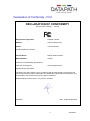
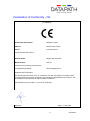
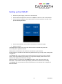
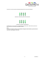
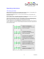
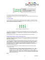
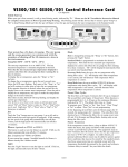
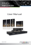
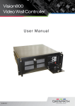
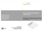
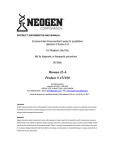
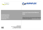
VQS-01 User Manual Datapath Limited Alfreton Road, Derby, DE21 4AD, England Tel: +44 (0) 1332 294441 Fax: +44 (0) 1332 290667 Email: [email protected] Web: http://www.datapath.co.uk 1 24/02/2011 Contents FCC Compliance.............................................................................................. 3 Declaration of Conformity - FCC ...................................................................... 4 Declaration of Conformity - CE ........................................................................ 5 Introduction ...................................................................................................... 6 Unpacking ........................................................................................................ 7 Description ....................................................................................................... 8 Front Panel ........................................................................................................................... 8 Rear Panel ............................................................................................................................ 8 Setting up the VQS-01 ................................................................................... 10 Operating Instructions .................................................................................... 12 VGA Analog Input Mode ..................................................................................................... 12 DVI Input Mode ................................................................................................................... 13 Display Data Channel (DDC) Preferred Timing ................................................................. 13 Output Refresh Rates ......................................................................................................... 15 Flip Image Output ........................................................................................................... 16 Multiple VQS-01 Units.................................................................................... 18 Resetting the VQS-01 .................................................................................... 19 Factory default Settings ...................................................................................................... 19 Resolution Table ............................................................................................ 20 Using VQS-01 with other Datapath Products ................................................. 22 Specification .................................................................................................. 23 Datapath Limited ............................................................................................ 24 Technical Support ............................................................................................................... 24 Copyright Statement ........................................................................................................... 24 UK Headquarters and Main Sales Office ........................................................................... 25 German Office ...................................................................... Error! Bookmark not defined. French Office ...................................................................................................................... 25 Index .............................................................................................................. 26 2 24/02/2011 FCC Compliance Federal Communications Commission Statement This device complies with FCC Rules Part 15. Operation is subject to the following two conditions: This device may not cause harmful interference, and This device must accept any interference received, including interference that may cause undesired operation. This equipment has been tested and found to comply with the limits for a Class B digital device, pursuant to Part 15 of the FCC Rules. These limits are designed to provide reasonable protection against harmful interference in a commercial, industrial or business environment. This equipment generates, uses and can radiate radio frequency energy and, if not installed and used in accordance with the manufacture’s instructions, may cause harmful interference to radio communications. However, there is no guarantee that interference will not occur in a particular installation. If this equipment does cause harmful interference to radio or television reception, which can be determined by turning the equipment off and on, the user is encouraged to try to correct the interference by one or more of the following measures: Re-orient or relocate the receiving antenna. Increase the separation between the equipment and the receiver. Connect the equipment to an outlet on a circuit different from that to which the receiver is connected. Consult the dealer or an experienced radio/TV technician for help. Warning! Any changes or modifications to this product not expressly approved by the manufacturer could void any assurances of safety or performance and could result in violation of Part 15 of the FCC Rules. Reprinted from the Code of Federal Regulations #47, part 15.193.1993. Washington DC: Office of the Federal Register, National Archives and Records Administration, US Government Printing Office. 3 24/02/2011 Declaration of Conformity - FCC DECLARATION OF CONFORMITY Per FCC Part 2 Section “. 1077(a) Responsible Party Name: Datapath Limited Address: Alfreton Road, Derby, Phone: +441332-294441 Hereby declares the product: Product Name: Display Wall Controller Model Number: VQS-01 Conforms to the following specifications: FCC Part 15 Subpart B Class B Digital Device Supplementary Information: This device has been shown to be in compliance with and was tested in accordance with the measurement procedures specified in the Standards & Specifications listed above and as indicated in the measurement report number: 03U2394-1 Representative Persons Name: Tony Jones, Chairman Signature: Date: 09 December 2003 4 24/02/2011 Declaration of Conformity - CE Per EN55022 Responsible Party Name: Datapath Limited Address: Alfreton Road, Derby, Phone: +441332-294441 Hereby declares the product: Product Name: Display Wall Controller Model Number: VQS-01 Conforms to the following specifications: CE Regulation EN55022 Class B Digital Device Supplementary Information: This device has been shown to be in compliance with and was tested in accordance with the measurement procedures specified in the Standards & Specifications listed above and as indicated in the measurement report number: 03U2394-2 Representative Persons Name: Tony Jones, Chairman Signature: Date: 10 Jan 2004 5 24/02/2011 Introduction The Datapath VQS-01 is a display wall controller that connects to the VGA output of any PC and displays the image across four screens. Each screen displays a quarter of the VGA image in a 2 x 2 format, as shown below. If used in conjunction with the Datapath range of multi-screen graphics cards, large display walls may be constructed by connecting the outputs of each graphics card to VQS-01 units. 6 24/02/2011 Unpacking Your packing box should contain the following items: The VQS-01 Display Wall Controller. The VQS-PSU Power supply unit. User Manual. Note: We recommend that you do not discard the packing box until you are completely satisfied with the VQS-01, and it is fully installed and working correctly. We also recommend that you make note of the serial number of the controller in a prominent place before you connect it to the computer. This should hasten any query should you need to contact our Technical Support Department. The serial number is displayed on the VQS-01 and the box label. 7 24/02/2011 Description Front Panel The front panel is made up of 3 specific areas: The LED panel. The Adjustment Buttons. Output Sockets LED’s The LED’s are marked A - H and are used to identify various operations of the VQS-01. The LED panel is covered in more detail later. Adjustment Buttons Adjustment operations can be made using the four buttons marked Select, -, +, and Save, again these are covered in more detail later. Output Sockets The output sockets are used to connect the VQS-01 to your four display monitors. Rear Panel The rear panel is made up of four specific areas: Sync sockets. Input sockets Power sockets Power LED’s 8 24/02/2011 Sync Sockets The Sync sockets are used when multiple VQS-01’s are connected together and it is required that all displays be locked. For most applications this is not necessary therefore connecting Sync in and out sockets is not normally required. For applications that do require all displays to be locked the following connections should be made: The first VQS-01 (Sync Out) conntects to the second VQS-01 (Sync In). The Second VQS-01 (Sync Out) connects to the third VQS-01 (Sync In) and so on. Warning! The equipment can be damaged if the Sync sockets are not connected as described above. Input Sockets The Input socket is used to connect the input source to the VQS-01. Power Sockets The Power In socket is where the power source is connected to the VQS-01. The VQS-PSU supplied with the VQS-01 is plugged into the Power In socket. The Power Out socket can be used if you possess a more powerful Power Supply Unit (PSU) which can link to multiple VQS-01 controllers. Datapath do not supply such power supply units. Power and Ready LED’s The Power and Ready LED’s indicate phases of operation, details of which are highlighted later in the manual. 9 24/02/2011 Setting up the VQS-01 Ensure the power supply for the PC is disconnected. Connect the VGA ouput from the PC to the Input socket on the rear of the VQS-01. Connect the four displays to the output sockets on the front panel of the VQS-01 as per the following illustration: Connect the VQS-PSU to the VQS-01 and switch on the power supply. Power up the PC. The Power LED located on the rear panel will illuminate to indicate that power has successfully been applied to the unit. When power is introduced to the VQS-01 the unit will carry out a self test. During operation, the VQS-01 will continuously determine the type of input, either analog VGA or digital DVI. If the Ready LED is not illuminated, this indicates that the unit is trying to locate a display mode. If the LED is blinking the unit does not recognise the display mode of the PC and therefore the display mode should be changed. When the VQS-01 is powered up the Ready LED will go off for a short time then stay illuminated. This indicates that the input display mode has been detected successfully. If the Ready LED is illuminated on power up and stays on, this indicates that no signal has been connected. 10 24/02/2011 The LED’s on the front panel will indicate analog VGA or DVI input as follows: Indicates a valid analog VGA mode detected. Indicates a valid DVI mode detected If neither the “A” nor “D” LED’s are illuminated this indicates that a valid video input has not been connected or has been connected incorrectly. Note: In order to modify the settings of the VQS-01 using the select buttons you must have a valid video input signal connected. 11 24/02/2011 Operating Instructions VGA Analog Input Mode When the VQS-01 is powered up successfully and the LED indicator “A” is illuminated. This indicates that an analog VGA input mode has been selected. If none of the LED indicators are on, check to ensure all cables are correctly fitted to the appropriate sockets. Once the LED indicator is illuminated, the VQS-01 will display the VGA video source across all four screens in a 2 x 2 format as illustrated in the Introduction When using a VGA analog source it may be necessary to make minor adjustments to the picture to enhance position and quality. These adjustments are saved on a per-input mode basis, see page 19 for a list of supported input resolutions/refresh rates. To make adjustments, press the Select button located on the front panel until the mode you require is displayed on the LED. The LED display will indicate which picture adjustment has been selected as follows. Sample Clock Adjustment Using the + and - buttons the sample clock can be adjusted Clock Phase Adjustment Using the + and - buttons the Clock Phase can be adjusted Horizontal Position Adjustment Using the + and - buttons the horizontal position can be adjusted. i.e. the display can be moved left and right. Vertical Position Adjustment Using the + and - buttons the vertical position can be adjusted. i.e. the display can be moved up and down Brightness Using the + and - buttons the image brightness can be adjusted 12 24/02/2011 Contrast Using the + and - buttons the image contrast can be adjusted. It is possible to save the settings for the particular VGA mode. Once adjustments have been made, press the Save button and the VGA mode will be saved for future use. DVI Input Mode If you have a DVI VGA source then the LED indicator panel will differ. As explained earlier, when the VQS-01 is powered up it will detect what source is connected, if the source is DVI then the LED panel will illuminate as follows: The “D” indicating a valid DVI source. The VQS-01 automatically detects the signal and translates it to the most optimum display, therefore, the adjustments to the sample clock, clock phase, positioning, brightness and contrast are not required. Other adjustments may be made for both analog and digital DVI sources as follows. Display Data Channel (DDC) Preferred Timing The DDC Preferred Timing is read from the VQS-01 by the PC BIOS and operating system to determine a preferred resolution on power-up. The Preferred Timing is read using the DDC output from the VQS-01. The EDID (Extended Display Identification Data) contains basic information about a monitor and its capabilities. In addition to the preferred timing, the EDID also contains secondary timing information for another resolution. Both the preferred and secondary timing are read by the operating system and graphics software and may be included in a list of userselectable resolutions. The VQS-01 provides the ability to simultaneously change both the preferred and secondary timing. The following table illustrates how to change the EDID preferred and secondary timings. To change the mode: Use the Select button and navigate through the settings until the “A” or “D” LED (depending on if you have analog or digital monitors connected) is lit the “H” LED is lit and the “B and “C” LEDs are not lit. At this stage the “E”, “F” and “G” LEDs indicate the current mode. Use the + and - buttons to navigate through the available modes as illustrated in the next table. When you reach the last of the available modes it will loop back to the first. Note: 13 24/02/2011 For illustration purposes the LED panel is indicating that a DVI source is connected i.e. the “D” LED is on. If a VGA source is connected the “A” LED would be illuminated: LED Panel Preferred Timing Secondary Timing 640 x 480 at 75Hz 1024 x 768 at 85Hz 800 x 600 at 75Hz 1280 x 960 at 85Hz 1024 x 768 at 75Hz 1440 x 900 at 60Hz 1280 x 1024 at 60Hz (Default) 2560 x 1536 at 30Hz (Default) 1280 x 1024 at 75Hz 1920 x 1080 at 60Hz 1600 x 1200 at 60Hz 2800 x 1050 at 30Hz 2048 x 1536 at 37.5 Hz 2560 x 1536 at 30Hz Once the correct mode is selected press the Save button 14 24/02/2011 Output Refresh Rates The Output Refresh Rate mode enables the user to change the current refresh rate of the display. A different output refresh rate is stored for each supported resolution and refresh rate (see table on page 19). If the Sync Input is used, changing the settings has no effect as the sync source determines the refresh rate. The table below illustrates how to change a specific Refresh Rate by navigating through the LED indicators. To change the Refresh Rate: Use the Select button and navigate through the settings until the “A” or “D” LED (depending on if you have analog or digital monitors connected) is lit as well as the “B” and “C” LED’s. Once you have reached this stage the “F”, “G” and “H” LEDs indicate the current output refresh rate. Use the + and - buttons to navigate through the available Refresh Rate modes as illustrated in the table on the next page. When you reach the last available refresh rate the LEDs will stop changing. The “E” LED indicates that the line double feature is enabled. Line doubling is either always enabled, an option, or always disabled depending on the input resolution (See table on page 20). If the line double feature is an option for the current input resolution then it may be enabled by pressing the + button until the “E” light is illuminated. By default the VQS-01 matches the output frame rate to the input frame rate, this eliminates motion artifacts. It is therefore recommended you adjust the refresh rate using the driving graphics card. If the incoming frame rate is less than 50Hz the outgoing frame rate is double the input rate by default. Note: For illustration purposes the LED panel is indicating that a DVI source is connected i.e. the “D” LED is on. If a VGA source is connected the “A” LED would be illuminated: 50Hz 56Hz 60Hz 15 24/02/2011 70Hz 72Hz 75Hz 85Hz Flip Image Output The Flip Image Output option enables the user to display the image as a flipped image i.e. upside down. To operate the Flip Image Output mode: Use the Select button and navigate through the settings until the “A” or “D” LED (depending on if you have analog or digital monitors connected) is lit, the “C” LED is lit but the “B” LED is not lit. Continue to press the Select button until the required Output has been located. The table below illustrates which LED’s should be displayed for which output. Use the + and - buttons to flip the image. Note: For illustration purposes the LED panel in the table is indicating that a DVI source is connected i.e. the “D” LED is on. If a VGA source is connected the “A” LED would be illuminated: Selecting this series of LED’s and using the + and - buttons will flip the image displayed in the top left screen (Output 1) 16 24/02/2011 Selecting this series of LED’s and using the + and - buttons will flip the image displayed in the top right screen (Output 2) Selecting this series of LED’s and using the + and - buttons will flip the image displayed in the bottom left screen (Output 3) Selecting this series of LED’s and using the + and - buttons will flip the image displayed in the bottom right screen (Output 4) Note: When making any adjustments to the settings, if the VQS-01 unit detects that no buttons have been pressed for a period of 60 seconds, the unit will revert to the last saved setting for the current mode selected. Settings are also restored if the Select button is pressed until only the “A” or “D” is illuminated: 17 24/02/2011 Multiple VQS-01 Units If multiple VQS-01 units are being used to create a larger display wall that requires all displays to be locked then it will be necessary to Gen-Lock all the outputs of each of the VQS01 units using the Sync In and Sync Out sockets on the rear panel. For most applications this is not necessary, therefore, the units should not normally be connected. To Gen-Lock the units, the output from one unit has to be connected to the input of the next one as illustrated below. Sync In Sync Out Sync In Sync Out Sync In Sync Out Sync In Sync Out The Sync In socket of the first unit (i.e. the bottom one in the illustration) and the Sync Out socket of the last unit should not be used. The Refresh Rate is controlled by the first unit. Note: The last unit in the chain SHOULD NOT be looped and connected to the first unit. 18 24/02/2011 Resetting the VQS-01 Factory default Settings The VQS-01 is shipped with a default setting for all modes and options. There may at sometime be a requirement to restore the modes and options to the default settings. To re-set all the modes and options to the factory default settings: Press the Select, the + and the Save buttons simultaneously The unit will then illuminate all 8 LED’s to confirm the default settings. Press Save to confirm or Select to cancel. To reset a particular mode or adjustment to the factory default setting the following steps should be taken: Navigate to the required mode that you wish to reset, i.e brightness or vertical position for example. Press the + and the - button simultaneously. The “A” or “D” and “B”, “C”, “E”, “F”, “G” and “H” will all be lit temporarily to indicate the value has been reset. Press Save to confirm. The setting for that particular mode will now be restored to the factory default. 19 24/02/2011 Resolution Tables VESA Modes Supported by VQS-01 Input Resolution Output Resolution 720 x 400 at 85Hz 4 x 720 x 400 at 85Hz – Each output line is doubled. 720 X 480 at 60Hz 4 x 720 x 480 at 60Hz – Each output line is doubled. 640 x 350 at 85Hz 4 x 640 x 350 at 85Hz – Each output line is doubled. 640 x 400 at 85Hz 4 x 640 x 400 at 85Hz – Each output line is doubled. 640 x 480 at 60, 72, 75 and 85Hz 4 x 640 x 480 at 60, 72, 75 and 85Hz – Each output line is doubled. 800 x 600 at 56, 60, 72, 75 and 85Hz 4 x 800 x 600 at 56, 60, 72, 75 and 85Hz - Each output line is doubled. 1024 x 768 at 60, 70, 75, and 85Hz 4 x 1024 x 768 at 60, 70, 75 and 85Hz – Each output line is doubled 1152 x 864 at 75Hz 4 x 576 x 432 at 75Hz – Line double optional. 1280 x 720 at 60Hz 4 x 1280 x 720 at 60Hz – Each output line is doubled. 1280 x 960 at 60 and 85Hz 4 x 640 x 480 at 60 and 85Hz – Line double optional. 1280 x 1024 at 60 and 75Hz 4 x 640 x 512 at 60 and 75Hz– Line double optional. 1440 x 900 at 60Hz 4 x 1440 x 900 at 60Hz – Each output line is doubled. 1600 x 1200 at 60Hz 4 x 800 x 600 at 60Hz Datapath Modes Supported by VQS-01. (Requires Datapath Vantage4 with driver V1.03 or iH4 with driver V2.14 or above) Input Resolution Output Resolution 2048 x 1536 at 30, 35 and 37Hz 4 x 1024 x 768 at 60, 70 and 75Hz 1600 x 1200 at 30, 36, 37, 42, 56 and 60Hz 4 x 800 x 600 at 60,72,75,85,56 and 60Hz 1280 x 960 at 60 and 85Hz 4 x 640 x 480 at 60 and 85Hz 20 24/02/2011 Custom Modes Supported by VQS-01 (Requires customized input mode with specific timing information) Input Resolution Output Resolution 720 x 400 at 70Hz 4 x 720 x 400 at 70Hz – Each output line is doubled. 2048 x 1536 at 25Hz 4 x 1024 x 768 at 50Hz 2304 x 1728 at 31 and 37Hz 4 x 1152 x 864 at 60 and 75Hz 2560 x 2048 at 23, 25 and 28Hz 4 x 1280 x 1024 at 70, 50 and 56Hz 1280 x 960 at 50, 72 and 75Hz 4 x 640 x 480 at 50, 72 and 75Hz 800 x 600 at 50Hz 4 x 800 x 600 at 50Hz – Each output line is doubled. 1280 x 700 at 85Hz 4 x 640 x 350 at 85Hz – Line double optional. 1280 x 800 at 85Hz 4 x 640 x 400 at 85Hz – Line double optional. 1440 x 800 at 85Hz 4 x 720 x 400 at 85Hz 1600 x 1200 at 50Hz 4 x 800 x 600 at 50Hz 1920 x 1080 at 60Hz 4 x 1920 x 1080 at 60Hz – Each output line is doubled. 2560 x 1536 at 30Hz 4 x 1280 x 768 at 60Hz Custom Modes Supported by VQS-01 (May require non-Datapath hardware as well as customized input mode with specific timing information) Input Resolution Output Resolution 648 x 481 at 60Hz 4 x 648 x 480 at 60Hz – Each output line is doubled. 1280 x 1024 at 50Hz 4 x 1280 x 1024 at 50Hz – Each output line is doubled. 1024 x 768 at 50Hz 4 x 1024 x 768 at 50Hz – Each output line is doubled. 800 x 600 at 50Hz 4 x 800 x 600 at 50Hz – Each output line is doubled. 1600 x 1200 at 50Hz 4 x 800 x 600 at 50Hz 2800 x 1050 at 30Hz 2 x 1400 x 1050 at 60Hz 21 24/02/2011 Using VQS-01 with other Datapath Products Up to four VQS-01 controllers can be used with a single Datapath iH4 graphics card. This increases the number of displays to sixteen. Simply connect each iH4 output to a single VQS-01 as shown in the following illustration: Providing sufficient PCI slots are available, it is possible to use up to nine iH4 cards and thirtytwo VQS-01 controllers. This configuration provides support for up to 144 displays. Note: The maximum resolution per display is 1024 x 768. 22 24/02/2011 Specification VQS-01 Physical Dimensions 248 x 175 x 55mm Operating Temperature Range 0 - 35 DegC Power Requirements 9 - 15V DC at 2 amps (max). Requires VQS PSU. (External PSU) Cooling The unit contains a cooling fan. The input and output vents should not be restricted. VGA Input 1 x DVI connector. Analog or digital Display Outputs 4 x DVI connectors Analog or digital Gen-Lock Input/Output 2 x RCA connectors. TTL voltage levels Power Connector 5 pin DIN VQS-PSU VQS-PSU Physical Dimensions 132 x 58 x 30mm Input Power 110 - 240v AC 50-60Hz Operating Temperature Range 0 - 35 DegC Output Power 12V DC at 3.75 amps (max) 23 24/02/2011 Datapath Limited Datapath has a long and very successful history in the computer graphics industry. Datapath has been designing and supplying high performance, high quality graphics display systems to the world’s largest and most demanding companies and institutions since 1982. Datapath was one of the founding companies of multi-screen Windows acceleration using single and multi board solutions. Now using the very latest display technology Datapath offers some of the world’s leading multi screen graphics accelerators for the most demanding applications. As new technology advances, so we at Datapath improve the performance and functionality of both our hardware and software to give our customers more. Following a continuous development program, we pride ourselves on our support and responsive nature towards all our customers and their changing needs. As more sophisticated equipment and techniques become readily available, so we are there to exploit the power and potential that this technology presents. Technical Support Registered users can access our technical support line using, email, and the Support page on the Datapath Web Site, usually with a response within 24 hours (excluding weekends). www.datapath.co.uk/suppnew.asp Via Email: Send an email to [email protected] with as much information about your system as possible. To enable a swift response we need to know the following details: Specification of the PC - including processor speed Operating System Application Software Datapath Hardware / Software The exact nature of the problem - and please be as specific as possible. Please quote version and revision numbers of hardware and software in use wherever possible. Copyright Statement © Datapath Ltd., England, 2006 Datapath Limited claims copyright on this documentation. No part of this documentation may be reproduced, released, disclosed, stored in any electronic format, or used in whole or in part for any purpose other than stated herein without the express permission of Datapath Limited. Whilst every effort is made to ensure that the information contained in this on-line help is correct, Datapath Limited make no representations or warranties with respect to the contents thereof, and do not accept liability for any errors or omissions. Datapath reserves the right to change specification without prior notice and cannot assume responsibility for the use made of the information supplied. All registered trademarks used within this documentation are acknowledged by Datapath Limited. 24 24/02/2011 UK Headquarters and Main Sales Office Datapath Limited Alfreton Road Derby, DE21 4AD Tel: +44 (0) 1332 294441 Fax: +44 (0) 1332 290667 Email: [email protected] Web: www.datapath.co.uk French Office Datapath France 7 rue des Pinsons 78990 Elancourt, France Tel: +33 1 30 13 89 34 Fax: +33 1 30 13 89 35 Email: [email protected] 25 24/02/2011 Index 2 x 2 format, 6 Adjustment Buttons, 8 Brightness, 12 change the mode, 13 Clock Phase Adjustment, 12 Connect the VGA ouput, 10 Contrast, 13 Datapath, 24 Datapath Web Site, 24 DDC output, 13 default setting, 19 DVI mode, 11 EDID, 13 email, 24 factory default, 19 FCC Rules, 3 Flip Image Output, 16 frame rate, 15 front panel, 8 Gen-Lock, 18 Horizontal Position Adjustment, 12 iH4 graphics card, 22 Input 1, 10 input frame rate, 15 Input Resolution, 20 Input Sockets, 9 last saved setting, 17 LED’s, 8 line double feature, 15 maximum resolution per display, 22 modify the settings, 11 multiple VQS01, 18 multi-screen graphics cards, 6 Operating Temperature, 23 26 24/02/2011 Output Refresh Rate, 14 Output Resolution, 20 output sockets, 10 Output Sockets, 8 packing box, 7 PC BIOS, 13 Physical Dimensions, 23 Power and Ready LED’s, 9 Power Requirements, 23 Power Sockets, 9 Preferred Timing, 13 Rear Panel, 8 re-set, 19 Sample Clock Adjustment, 12 Save, 13 save the settings, 13 Sync In, 18 Sync Out, 18 Sync Sockets, 9 technical support, 24 valid video input, 11 Vertical Position Adjustment, 12 VESA, 20 VGA mode, 11 27 24/02/2011 28 24/02/2011