1
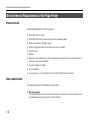
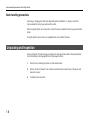
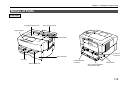
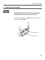
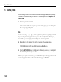
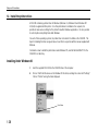
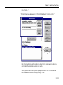
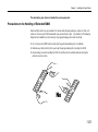
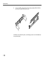
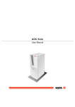
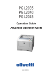
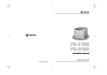
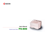
Chapter 1 Installing the Page Printer
Chapter 1
Installing the Page
Printer
This chapter uses illustrations to explain the names of parts of this
printer, how to use it, its environmental requirements, and how to
install it.
Environmental Requirements of the Page Printer................
Unpacking and Inspection....................................................
Moving the Printer................................................................
Names of Parts ....................................................................
Setup and Connections........................................................
Expanding Memory ..............................................................
1-2
1-6
1-8
1-9
1-11
1-32
1-1
Environmental Requirements of the Page Printer
Environmental Requirements of the Page Printer
Places to Avoid
Avoid installing the printer in locations subject to:
•
•
•
•
•
•
•
Direct drafts of hot or cold air
•
•
•
Excessive sunlight or humidity
Direct drafts from outside (Avoid locations near doors leading outside.)
Sudden temperature or humidity changes
Sources of high temperature, for example, near stoves or radiators
Excessive dust
Vibration
Ammonia or other harmful fumes. (If you are planning to fumigate the room, or make liberal use of
insecticide, remove the printer first!)
Lack of ventilation
Low air pressure, e.g., located more than 2000 meters (6500 feet) above sea level.
Basic requirements
The printer will work best if it is installed in a location that is:
•
1-2
Near the computer
If the parallel interface is used to connect the printer to the computer, the connecting cable should
be shielded type and not be longer than 3 meters (10 feet).
Chapter 1 Installing the Page Printer
•
Level and well supported
Place the printer on a sturdy table or desk. Do not place the printer on an unstable cart, stand, or
table. The printer may fall, causing injury, or serious damage to the printer.
•
Near an AC wall outlet, preferably one that can be used for the printer alone (see section
Power Supply on next page.)
•
Only use this printer under the voltage listed on the serial number label attached to the rear
panel of the printer.
Power requirements are:
Voltage
Frequency
Current capacity
120 V (U.S.A.), 220–240 V (European countries, Australia, Asia)
±10% at each voltage
60 Hz (120 V), ±2%
50 Hz (220–240 V), ±2%
Max. 5.6 A at 120 V, or Max. 2.8 A at 230 V
The outlet should be earthed, or an adapter should be used.
If an extension cord is used, the total length of the power cord plus extension should be 5 meters
(17 feet) or less.
•
Well ventilated, not too hot or cold, and too damp or dry
Temperature
Humidity
10°C to 32.5°C, ideally about 23°C (50°F to 90.5°F, ideally about 73.4°F)
20% to 80%, ideally 60%
If you install the printer where the temperature or humidity is outside the above ranges, you may not
get the best print quality, and there will be an increased chance of paper jams.
1-3
Environmental Requirements of the Page Printer
Power Supply
The printer should not be on the same power circuit as an air conditioner, fluorescent light, copier, or
shredder, because these devices generate electrical noise on the power line. If it must share a power
circuit with equipment like this, a high-frequency noise filter or isolation transformer is advisable.
(Filters and transformers are available commercially.)
Avoid using plug multipliers to connect a large number of devices on the same circuit as the printer.
If the power from the outlet itself appears to be unstable, a line stabilizer should be used. In places
where the voltage tends to fluctuate, it may be necessary to install a voltage regulator.
As the disconnect device is not incorporated in the printer’s AC primary circuit, an easily
accessible socket outlet must be provided near the equipment.
Da kein Trennschalter in den Wechselstrom-Primärkreis des Druckers eingebaut ist, muß
eine leicht zugängliche Steckdose in der Nähe des Gerätes vorhanden sein.
1-4
Chapter 1 Installing the Page Printer
Grounding
Be sure to connect the ground wire for the printer's power supply to the ground terminal of the power
outlet, to a copper pole buried at least 65 cm (25 inches) in the ground, or to a water pipe approved by
the water department for use as a ground.
WARNING
Never use a gas pipe as a ground, as this may result in fire.
Surrounding space
Space surrounding the location where the printer is installed is required as shown below for purposes
of ventilation and maintenance.
WARNING
Be sure to secure enough space surrounding the printer. Continued use without enough
space may cause heat to build up within the printer, resulting in fire.
30 cm (11.8 inches)
40 cm (15.7 inches)
5 cm (2 inches)
25 cm (9.8 inches)
50 cm (19.6 inches)
1-5
Environmental Requirements of the Page Printer
Basic handling precautions
Removing or changing parts other than disposable parts is prohibited. For repairs, contact the
Kyocera dealer from which you purchased the printer.
When moving the printer to a new location, contact the Kyocera dealer from which you purchased the
printer.
Using this printer to print currency or negotiable bonds is in violation of the law.
Unpacking and Inspection
Remove the printer from the package according to the steps given below. After removing the printer,
check that nothing is missing against the list of packaged contents.
1-6
1.
Place the box containing the printer on a flat, stable surface.
2.
Remove the User’s Manual, Toner Container and other items located on top of the spacer and
remove the spacer.
3.
Carefully remove the printer.
Chapter 1 Installing the Page Printer
List of packaged contents
Contents of Printer Box
Printer (FS-800)
User’s Manual
Power Cord
Cleaning Cloth
Toner Container (TK-16H)
Kyocera Digital Library CD-ROM
1-7
Moving the Printer
Moving the Printer
Note the following items when moving the printer.
Be sure to lift the printer gently, keeping it horizontal, to prevent toner from soiling the inside of the
printer.
1-8
&KDSWHU,QVWDOOLQJWKH3DJH3ULQWHU
1DPHVRI3DUWV
)URQW9LHZ
)DFH'RZQ2XWSXW7UD\
)DFH8S2XWSXW7UD\
3DSHU6WRSSHU
&RQWURO3DQHO
3RZHU&RUG
&RQQHFWRU
3DSHU&DVVHWWH
6XE7UD\
3DUDOOHO,QWHUIDFH
&RQQHFWRU
0DQXDO)HHG7UD\
6ORW&RYHUIRU,QVWDOODWLRQ
RI2SWLRQDO,QWHUIDFH
3RZHU6ZLWFK
Names of Parts
Interior View
Top Cover
Process Unit
Toner Container Release Lever (Green)
1-10
Chapter 1 Installing the Page Printer
Setup and Connections
Set up the printer according to the following steps.
1.
2.
3.
4.
5.
6.
7.
8.
9.
10.
11.
12.
Install the printer on the paper feeder. (Option)........................................................... (See p.1-12)
Remove the process unit protective cover. ................................................................ (See p.1-13)
Install the toner container. .......................................................................................... (See p.1-15)
Close the top cover. .................................................................................................... (See p.1-16)
Add paper. .................................................................................................................. (See p.1-17)
Open the paper stopper on the face-down tray........................................................... (See p.1-20)
Open the face-up output tray (when the tray is being used). ..................................... (See p.1-20)
Connect the printer to the computer. .......................................................................... (See p.1-21)
Attach the power cord. ................................................................................................ (See p.1-23)
Test the printer. .......................................................................................................... (See p.1-24)
Test the interface with the computer. ......................................................................... (See p.1-25)
Install the printer driver. .............................................................................................. (See p.1-26)
1-11
Setup and Connections
1.
Install the printer on the paper feeder. (Option)
Align the installation holes on the bottom of the printer with the positioning pins on top of the paper
feeder and slowly lower the printer into place. Check that the connector on top of the paper feeder is
properly connected to the connector on the bottom of the printer.
Connector
Optional Paper Feeder (PF-16)
1-12
Positioning Pins
Chapter 1 Installing the Page Printer
2.
Remove the process unit protective cover.
1.
Open the printer top cover all the way.
Top Cover
Process Unit
Protective Cover
Process Unit
2.
Lift the process unit out of the printer. The drum in the process unit is sensitive to light. Do
not expose the drum even to normal office lighting (500lux) for more than five minutes.
Process Unit
1-13
Setup and Connections
3.
Pull and remove the process unit protective cover and give the process unit a horizontal shake of
4 to 5 times.
Process Unit
Protective Cover
Shake four or five times
Process Unit
4.
1-14
Install the process unit in the printer. In doing so, carefully align the guides at the both ends of the
process unit properly with the slots in the printer.
Chapter 1 Installing the Page Printer
3.
Install the toner container.
1.
Take the toner container from the bag. Shake the toner container with the protective seal (orange
colored) facing up as shown in the figure five times or more to thoroughly mix the toner inside.
Toner Container
Shake five or more
times
Protective Seal
(Orange colored)
2.
Carefully remove the protective seal as shown in the diagram.
3.
Align the ends of the toner container with the grooves to the left and right inside the and install.
Toner Container
Grooves
1-15
Setup and Connections
4. Check that the toner container is installed in the correct position, and push forcefully on the top of
the toner container at “PUSH HERE.”
4.
Close the top cover.
Close the top cover.
1-16
Chapter 1 Installing the Page Printer
5.
Add paper.
Try as much as possible to use fresh paper which has just been opened. Paper which has been
stored long periods contains moisture and may result in sheets sticking together and/or paper jams.
For specifications on the paper which can be used with this printer, refer to Appendix B Paper
Selection.
1.
Pull the paper cassette all the way out of the printer.
2.
Open the cassette cover all the way.
Cassette Cover
1-17
Setup and Connections
3.
Adjust the position of the paper stopper located at the rear of the cassette. While holding up the
paper stopper, slide the paper stopper to the desired paper size.
4.
Adjust the position of the paper guides located on the left and right side of the cassette. Align the
paper guides to the desired paper size by lifting the paper guides so they slide.
Move the side guides inward to where they just touch the edges of the paper.
Do not load more paper than will fit under the load limits on the top of the paper guides. (The
cassette will hold approximately 150 sheets of paper with a 80 g/m2 (21 lb) basis weight, or with a
thickness of 108 microns.
Load Limit
1-18
Chapter 1 Installing the Page Printer
5.
Close the cassette cover.
Cassette Cover
6.
Insert the paper cassette into the slot in the printer. Push it straight in as far as it will go.
1-19
Setup and Connections
6.
Open the paper stopper on the face-down tray.
Raise the paper stopper on the face-down tray as shown in the figure.
Paper Stopper
7.
Open the face-up output tray (when the tray is being used).
Use the face-up output tray when you wish paper to be stacked with the printed side facing up
(reverse order). The face-up output tray is located on the back side of the printer. Use it by opening
as shown in the figure.
Face-up output tray
1-20
Chapter 1 Installing the Page Printer
8.
Connect the printer to the computer.
CAUTION
Before performing this step, be sure to turn off the printer's power switch and unplug the
power plug from the power outlet. Failure to do so may result in electric shock.
A standard Centronics parallel interface connector (
pin connections, please refer to Appendix C.
) is located on the rear side of the printer. For
Option Interface Slot Cover
Parallel Interface Connector
1-21
Setup and Connections
Parallel Interface Connection
1.
Plug one end of the printer cable into the connector on the printer marked with a
symbol.
2.
Close the clips on both sides to fix the connector in place.
(parallel)
Clips
Printer Cable
Rear panel
3.
1-22
Plug the other end of the printer cable into the computer’s parallel (Centronics) interface
connector. This connector is usually labled PRINTER. For details, refer to the hardware
manual for the computer.
Chapter 1 Installing the Page Printer
9.
Attach the power cord.
CAUTION
Be sure the printer's power switch is turned off.
Note _____________________________________________________________________
Only use the power cord supplied with the printer.
1.
Plug the power cord into the power cord connector on the rear side of the printer.
Power Cord Connector
Power Cord
2.
Connect the other end of the power cord into a power outlet.
WARNING
Be sure to connect the ground wire of the printer to ground.
1-23
Setup and Connections
10. Test the printer.
Use the following procedure to test the printer and print out a status page indicating factory settings.
For details on the indicators and keys on the printer’s control panel, please refer to Chapter 2 The
Control Panel.
1.
Turn on the printer's power switch.
It does not matter whether the computer's power is on or off. Self test will be displayed in
the message display of the printer
Note _______________________________________________
An error message Top cover Open will be displayed in the printer’s message display unless the
top cover on the printer is properly closed or the process unit is correctly installed. If this happens,
check that the top cover is properly closed and the process unit is correctly installed.
2.
Wait until the ON LINE indicator lights and Ready appears in the message display.
If the ON LINE indicator is off, make it light by pressing the ON LINE/+ key.
3.
Press the ENTER/STATUS key. Information such as the memory allocation, etc., currently set for
the printer will be printed on a page in a list.
If the status page prints without problems, you can tell that the developer unit and paper feed cassette
are installed properly. For details on the contents of the status page, see Chapter 2.
1-24
Chapter 1 Installing the Page Printer
11. Test the interface with the computer.
In order to check that the printer and the computer are properly connected you must print by sending
an actual command from the computer.
1.
Turn on the printer's power switch and turn on the computer’s power as well.
2.
Wait until the ON LINE indicator lights.
3.
Enter and execute the following command at the DOS prompt on the computer screen.
ECHO !R! STAT; EXIT;>PRN
If this causes the printer to print a status page, then the printer and computer are properly connected.
If this does not print a status page, check that the printer cable is properly connected. The cable or
one of the connectors may also be broken.
Notes on Application Software
The computer and printer have been successfully connected by the procedures up to this point. In
order to print from software run on the computer, it is necessary to install a printer driver on the
computer to which the printer is connected. After the printer driver is installed, be sure to make proper
printer settings from within the software.
1-25
Setup and Connections
12. Install the printer driver.
A CD-ROM containing a printer driver for Windows (Windows 3.1, Windows 95 and Windows NT
3.51/4.0) is supplied with this printer. Once this printer driver is installed on the computer, it is
possible to make various settings for this printer from within Windows applications. It is also possible
to control options and printing from within Windows.
For each of these operating systems, the printer driver is located in the folder on the CD-ROM. The
steps for installing this driver are given below. Read this in conjunction with the manual supplied with
Windows.
For details on how to install the printer driver under Windows NT, read the file README.TXT in the
CD-ROM's root directory.
Installing Under Windows 95
1.
Insert the supplied CD-ROM into the CD-ROM drive of the computer.
2.
Click on “Start” with the mouse on the Windows 95 Task Bar, and align the cursor with “Settings.”
Click on “Printers” among the items displayed.
Start Button
1-26
Chapter 1 Installing the Page Printer
3.
The printer folder will open. Double click on “Add printer.”
4.
The Printer Wizard screen will appear. Click on “Next >.”
5.
A screen for selecting the printer to be either a local printer or network printer will appear. Select
the appropriate connection and click on “Next.”
6.
Next, “Click the manufacturer and model of your printer....” screen will appear. At this point,
select “Have Disk…” located at the lower right. (See the figure for Step 7.)
7.
Enter “[CD-ROM Drive Name]:\” as the source from which to copy the file and click on “OK.”
1-27
Setup and Connections
8.
Select “Kyocera FS-800,” click on “Next >,” and follow the on-screen instructions to install.
Once the driver has been properly installed, a Kyocera printer icon will be added to the Printers
folder.
Note _____________________________________________________________________
When printing under Windows 95, be sure to set the emulation of this printer to HP LaserJet 5Si
(default setting).
1-28
Chapter 1 Installing the Page Printer
Installing Under Windows 3.1
1.
Insert the supplied CD-ROM into the CD-ROM drive of the computer.
2.
Double click on the Control Panel.
3.
Double click on “Printers.”
1-29
Setup and Connections
4.
Click on “Add >>.”
5.
A screen for “List of Printers:” will appear. From the choices, click on “Install Unlisted or Updated
Printer.”
4.
5.
1-30
Chapter 1 Installing the Page Printer
6.
Click on “Install….”
7. The Install Driver menu will appear. Enter “[CD-ROM Drive Name]: \” and click on “OK.”
6.
8.
Refer to the Readme.txt file at the root directory of the CD-ROM and browse to the directory
which contains the appropriate drivers for your country.
9.
Select “Kyocera FS-800” from the printers displayed and click on “OK.” Once the driver has
been installed, close the Control Panel by clicking on “Close.”
1-31
Expanding Memory
Expanding Memory
The printer comes standard equipped with 4 MB of main memory. However, more complex pages can
be printed and processing speed increased by expanding the printer's memory. There is one slot
available in the printer for expanding memory. Printer memory can be expanded to up to 36 MB by
installing optional extended memory chip (SIMM) in the slot.
Note _____________________________________________________________________
The expansion memory should be installed only by a Kyocera authorized dealer or Kyocera certified
technician. Kyocera shall not be liable for damage due to improper installation of the expansion
memory.
Memory Required by the Printer Environment
It may be necessary to extend memory depending on the operating environment of the printer. Please
refer to the table below for minimum memory requirements in various environments.
Environment
HP LaserJet 5Si/KPDL
HP LaserJet 5Si/KPDL, resource protection
1-32
Resolution
300 dpi
600 dpi
4 MB
4 MB
—
10 MB
Chapter 1 Installing the Page Printer
The description given below is intended for service personnel.
Precautions on the Handling of Extended SIMM
Static electricity which may accumulate in the human body through walking on carpets or other such
surfaces is the enemy of SIMM loaded with many semiconductor chips. Pay attention to the following
things before installation to protect memory chips against damage from static electricity.
•
•
•
Do not remove the SIMM from their anti-static bag until immediately prior to installation.
Eliminate any static electricity from your body through grounding before touching the SIMM.
Be absolutely sure when handling the SIMM to hold them by the substrate without touching the
printed connector section.
Yes
No
1-33
Expanding Memory
Installing SIMM
Insert the SIMM into the socket on the printer's main board.
WARNING
Take precautions that no foreign substances such as metal chips or liquid get inside the
printer during the installation process. Operation of the printer during the presence of a
foreign substance may lead to fire or electric shock.
CAUTION
Be sure to turn off the printer's power and disconnect all cables when installing SIMM in the
printer. Failure to do so may lead to electric shock.
1-34
Chapter 1 Installing the Page Printer
Draw the main circuit board all way out of the printer as follows:
1.
Turn the printer’s power off. Unplug the printer’s power cable and disconnect it from the
host computer.
2.
Remove the two screws from the printer’s rear cover.
Screws
1-35
Expanding Memory
3.
Pull the main circuit board all the way out of the printer.
Caution
Before pulling the main board out, clean the area on the table, etc., at the back of the printer’s
rear panel. Foreign objects, if accidentally stuck to the back of the main board, may cause
serious damage to the printer.
Socket
1-36
Chapter 1 Installing the Page Printer
4.
Insert the connector end of the SIMM into the socket. Carefully push the board upright until it
snaps into place. Make sure that the catches at the ends of the socket fit into the holes at the
ends of the SIMM board.
Catch
Socket
1-37
Expanding Memory
5.
To remove the SIMM, carefully pull the end catches sideways slightly and tilt the SIMM to the
left as shown, then pull the SIMM out of the socket.
After SIMM has been installed in the printer, use the following procedure to check that installation has
been performed properly.
1-38
Chapter 1 Installing the Page Printer
Testing Extended Memory
1.
Check that the power switch is off, plug the power cord into the printer, and turn the power on.
2.
Wait for the printer’s ON LINE indicator to light and the message display to read Ready, then
press ENTER/STATUS key briefly.
3.
If installation has been performed properly, a status page will be printed. Check the Memory in
the upper right. Information on the SIMM installed in slot is shown here. There is no problem if
total memory has increased. (The printer is shipped from the factory with 4096 KB [4 MB] of
memory.)
1-39