1
SierraNet M408
User Manual
Software Version 1.70
Generated: December 15, 2014, 09:58
Teledyne LeCroy Protocol Solutions Group
Trademarks and Servicemarks
Teledyne LeCroy, CATC Trace, and SierraNet Protocol Suite are trademarks of Teledyne LeCroy.
Microsoft and Windows are registered trademarks of Microsoft Corporation.
Intel and Pentium are registered trademarks of Intel Corporation.
All other trademarks and registered trademarks are property of their respective owners.
THE SPECIFICATIONS AND INFORMATION REGARDING THE PRODUCTS IN THIS MANUAL ARE SUBJECT TO CHANGE WITHOUT NOTICE. ALL INFORMATION, EXAMPLES AND RECOMMENDATIONS IN THIS MANUAL ARE BELIEVED TO BE ACCURATE BUT ARE REPRESENTED WITHOUT WARRANTY OF ANY KIND, EXPRESS OR IMPLIED. USERS ARE FULLY RESPONSIBLE FOR THEIR APPLICATION OF ANY PRODUCTS.
THE SOFTWARE LICENSE AND LIMITED WARRANTY FOR THE ACCOMPANYING PRODUCT ARE SET FORTH IN INFORMATION THAT SHIPPED WITH THE PRODUCT AND ARE INCORPORATED HEREIN BY THIS REFERENCE. IF YOU ARE UNABLE TO LOCATE THE SOFTWARE LICENSE OR LIMITED WARRANTY, CONTACT Teledyne LeCroy FOR A COPY.
© 2012 Teledyne LeCroy, Inc. All rights reserved.
This document may be printed and reproduced without additional permission, but all copies should contain this copyright notice.
WEEE Program Teledyne LeCroy 3385 Scott Blvd.
Santa Clara, CA 95054
TEL: 800‐909‐7112 (USA and Canada)
TEL: 408‐653‐1260 (worldwide)
SierraNet M408 User Manual
ii
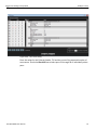
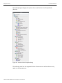
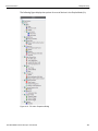
Contents
Chapter 1: Introduction...........................................................................................1
1.1 Analyzer Overview.................................................................................................................. 1
1.1.1 Receiving Your Analyzer .......................................................................................................................2
1.1.2 Unpacking the Analyzer .........................................................................................................................2
1.1.3 Analyzer Features...................................................................................................................................2
1.1.4 LEDs ........................................................................................................................................................3
1.1.5 Status and Configuration Display .........................................................................................................5
1.1.6 LCD Display and Button Functions for Configuring the Analyzer.....................................................5
1.2 Installing Your Analyzer......................................................................................................... 7
1.2.1 Software Installation ..............................................................................................................................7
1.3 Hardware Setup ...................................................................................................................... 7
1.3.1 Connecting in General ...........................................................................................................................7
1.3.2 Cables to Use ..........................................................................................................................................8
1.4 Expandability .......................................................................................................................... 8
1.4.1 Removing Expansion Cards ..................................................................................................................9
1.4.2 Daisy-Chaining with CATC SYNC Expansion Cards .........................................................................12
1.5 Launching Your Analyzer .................................................................................................... 14
1.5.1 Using the Software ...............................................................................................................................14
1.5.2 Add Device to Project ..........................................................................................................................15
1.5.3 Device Management .............................................................................................................................16
1.5.4 Connecting via Ethernet ......................................................................................................................21
1.5.5 Connecting Via USB .............................................................................................................................27
1.5.6 Update Device .......................................................................................................................................28
1.6 Protocol Analyzer ................................................................................................................. 30
1.6.1 Easy and Advanced Modes .................................................................................................................30
1.6.2 Viewing Captured Data ........................................................................................................................30
1.6.3 Preferences ...........................................................................................................................................30
1.6.4 Port Status ............................................................................................................................................31
1.7 InFusion................................................................................................................................. 31
1.8 CrossSync Control Panel..................................................................................................... 31
SierraNet M408 User Manual
iii
Teledyne LeCroy
Contents
1.8.1 Launching the CrossSync Control Panel...........................................................................................31
Chapter 2: Protocol Analysis ...............................................................................33
2.1 Starting a New Project.......................................................................................................... 34
2.2 Opening an Existing Project................................................................................................ 35
2.3 Closing an Existing Project ................................................................................................. 35
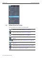
2.4 Software Menus and Toolbar............................................................................................... 36
2.5 Application Menu Options ................................................................................................... 38
2.5.1 File .........................................................................................................................................................38
2.5.2 Setup......................................................................................................................................................39
2.5.3 Analysis.................................................................................................................................................41
2.5.4 Navigation .............................................................................................................................................46
2.5.5 View .......................................................................................................................................................47
2.5.6 Window..................................................................................................................................................48
2.5.7 Help........................................................................................................................................................48
2.6 Analyzer Settings.................................................................................................................. 49
2.6.1 Device Pane ..........................................................................................................................................49
2.6.2 Probe Calibration..................................................................................................................................51
2.6.3 Port Status Pane...................................................................................................................................58
2.6.4 Session Control Pane ..........................................................................................................................59
2.6.5 Recording Settings Pane .....................................................................................................................59
2.6.6 Trigger/Filter Settings Pane.................................................................................................................62
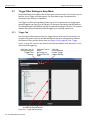
2.7 Trigger Filter Settings in Easy Mode .................................................................................. 64
2.7.1 Trigger Tab............................................................................................................................................64
2.7.2 Filter Tab ...............................................................................................................................................65
2.7.3 Patterns and Data Capture Setup .......................................................................................................71
2.7.4 Pre- and Post Trigger Data Capture....................................................................................................71
2.7.5 Triggering/Filtering Patterns (Easy Mode) .........................................................................................71
2.7.6 Timers/External.....................................................................................................................................72
2.7.7 Pattern Editing Conventions ...............................................................................................................73
2.7.8 Ethernet Patterns..................................................................................................................................74
2.7.9 FC Patterns (Easy Mode) .....................................................................................................................94
2.7.10 Trigger Setup ....................................................................................................................................101
2.8 Advanced Mode (User-Defined) ........................................................................................ 104
2.8.1 Working in Advanced Mode ..............................................................................................................104
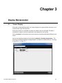
Chapter 3: Display Manipulation .......................................................................113
3.1 Viewer Display .................................................................................................................... 113
3.2 Quick View........................................................................................................................... 116
3.3 Switching Views.................................................................................................................. 117
iv
SierraNet M408 User Manual
Contents
Teledyne LeCroy
3.3.1 Decoding Assignments......................................................................................................................117
3.3.2 Spreadsheet View...............................................................................................................................118
3.3.3 Frame Inspector View ........................................................................................................................128
3.3.4 Traffic Summary View ........................................................................................................................131
3.3.5 Reassembly of Frames ......................................................................................................................132
3.3.6 Source and Destination Columns in Traffic Summary View .........................................................133
3.3.7 Data View.............................................................................................................................................134
3.3.8 Customize Display..............................................................................................................................135
3.3.9 Toolbars ..............................................................................................................................................136
3.3.10 Status Bar..........................................................................................................................................138
3.3.11 Search Status....................................................................................................................................138
3.4 Filtering................................................................................................................................ 138
3.4.1 Filter Setup..........................................................................................................................................139
3.5 Using Cursors ..................................................................................................................... 142
3.5.1 Cursors................................................................................................................................................142
3.6 Find ...................................................................................................................................... 144
3.6.1 Save Find Setup..................................................................................................................................145
3.6.2 Search From........................................................................................................................................146
3.6.3 Find Direction .....................................................................................................................................146
3.6.4 Find Logic ...........................................................................................................................................146
3.6.5 Finding LUNs and LBAs ....................................................................................................................146
3.6.6 Data Pattern Search ...........................................................................................................................147
3.7 Preferences ......................................................................................................................... 149
3.7.1 Software Settings ...............................................................................................................................150
3.7.2 Port Alias.............................................................................................................................................153
3.7.3 Address Alias......................................................................................................................................154
3.7.4 Display Settings..................................................................................................................................155
3.8 Help Menu............................................................................................................................ 160
3.8.1 Tell Teledyne LeCroy .........................................................................................................................160
3.8.2 Help Topics .........................................................................................................................................160
3.8.3 License Information ...........................................................................................................................160
3.8.4 Check for Updates..............................................................................................................................161
3.8.5 Shortcut List .......................................................................................................................................161
3.8.6 About ...................................................................................................................................................162
Chapter 4: InFusion ............................................................................................163
4.1 InFusion Overview.............................................................................................................. 163
4.2 Key Features ....................................................................................................................... 164
4.3 Infusion Control Interface .................................................................................................. 165
4.4 InFusion Scenario Manager Interface............................................................................... 166
SierraNet M408 User Manual
v
Teledyne LeCroy
Contents
4.5 Port Configuration for InFusion ........................................................................................ 166
4.6 InFusion Scenarios............................................................................................................. 167
4.6.1 Scenario Overview .............................................................................................................................167
4.6.2 Jam Details..........................................................................................................................................170
4.6.3 Scenario Events..................................................................................................................................170
4.6.4 Scenario Actions ................................................................................................................................181
4.6.5 Available Resources ..........................................................................................................................191
4.6.6 Using Counters in Events and Actions ............................................................................................192
4.6.7 Capturing a Data Dword.....................................................................................................................193
4.6.8 Using Captured Data Dwords............................................................................................................193
4.6.9 Dword Matcher....................................................................................................................................195
4.6.10 Reusing “Captured DWORDS” in Events.......................................................................................195
4.6.11 Global Rules......................................................................................................................................197
4.6.12 Sequences.........................................................................................................................................198
4.6.13 Scenario Libraries ............................................................................................................................199
4.6.14 Traffic Direction ................................................................................................................................199
4.6.15 Copy and Paste Scenarios .............................................................................................................200
4.6.16 Copy and Paste Library ...................................................................................................................201
4.6.17 Copy/Cut and Paste States..............................................................................................................203
4.6.18 Copy/Cut and Paste Conditions......................................................................................................203
4.6.19 Copy/Cut and Paste Events.............................................................................................................203
4.6.20 Marker Trigger ..................................................................................................................................203
4.6.21 Synch Jammer Scenarios with Jammer Internal Triggers ...........................................................206
4.7 Scenario Example............................................................................................................... 209
4.7.1 Example: Insert DWORD Matcher .....................................................................................................209
4.7.2 Sequence Creation .............................................................................................................................213
4.7.3 Summary of Scenario Creation .........................................................................................................214
4.8 Running Scenarios ............................................................................................................. 214
Chapter 5: Batch Scenario .................................................................................217
5.1 Using the Batch Scenario Feature .................................................................................... 217
5.1.1 Interface...............................................................................................................................................219
5.2 Batch Scenario Overview................................................................................................... 219
5.2.1 Adding Commands.............................................................................................................................220
5.2.2 Adding Events ....................................................................................................................................224
5.2.3 State Transition ..................................................................................................................................227
5.2.4 Global Variables .................................................................................................................................228
vi
SierraNet M408 User Manual
Contents
Teledyne LeCroy
Appendix A: China Restriction of Hazardous Substances Table ...................233
Appendix B: How to Contact Teledyne LeCroy................................................235
Index:.................................................................................................................. 237
SierraNet M408 User Manual
vii
Teledyne LeCroy
viii
Contents
SierraNet M408 User Manual
Chapter 1
Introduction
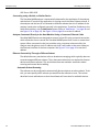
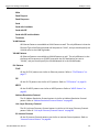
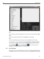
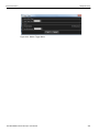
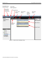
This manual describes installation and operation of the Teledyne LeCroy SierraNet M408™ Fibre Channel over Ethernet (FCoE) Protocol Analyzer and includes examples of typical applications.
Figure 1.1 Teledyne LeCroy SierraNet M408 Protocol Analyzer
1.1
Analyzer Overview
The SierraNet M408 analyzer is Teledyne LeCroy's 10 Gigabit Ethernet, 40 Gigabit Ethernet and 16
Gigabit Fibre Channel Analyzer and Jammer platform. The M408 has eight SFP+ 10GigE / 16G FC and two QSFP 40GigE ports. The M408 is very portable and can also be rack mounted (1U form‐factor). Up to 64 GB of capture memory allow extensive line‐speed capturing. The analyzer supports “Super Jumbo” packets up to 64K.
The M408 ports allow signals to pass through without re‐timing, ensuring that the test platform is as transparent as possible. The analyzer can be controlled either via an 1GbE connection to the local network or via a USB connection. The SierraNet M408 provides the user with an easy to understand control panel and LED indicators.
Major features of the M408 include triggering on back‐to‐back events, use of counters within trigger conditions, and multi‐state (up to 24) triggering and filtering state machines with four transitions per state.
SierraNet M408 User Manual
1
Teledyne LeCroy
1.1.1
Analyzer Overview
Receiving Your Analyzer
The analyzer package includes the following components:
1.1.2
SierraNet M408 Analyzer identified in the packing list
SierraNet M408 Quick Start
USB A‐B 3.0 cable, 1 meter
USB A‐B 2.0 cable, 1.8 meter
Ethernet cable, 10 feet
Three‐Prong AC power cord
C13‐C14 10A power cord, 2 meter
Installation CD ROM with software and documentation
Unpacking the Analyzer
Inspect the received shipping container for any damage. Unpack the container and account for each of the system components listed on the accompanying packing list. Visually inspect each component for absence of damage. In the event of damage, notify the shipper and Teledyne LeCroy. Retain all shipping materials for shipper’s inspection.
1.1.3
Analyzer Features
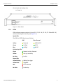
The Analyzer has the following features:
Power Switch
Speed, Link and Status LEDs (see next page)
Ports 1 and 2 connector pair
Ports 3 and 4 connector pair
Ports 5 and 6 connector pair
Ports 7 and 8 connector pair
Ports 9 and 10 connector pair
Status and Configuration LCD Display
Front Panel Configuration Buttons
External Trigger Input and Output
USB port for host connectivity
Ethernet port for network connectivity
CrossSync Control Panel
Figure 1.2: Front Panel
2
SierraNet M408 User Manual
Analyzer Overview
Teledyne LeCroy
On the back, the Analyzer has:
Power In
Figure 1.3: Back Panel
1.1.4
LEDs
LEDs indicators support each port link pair (P1 ‐ P2; P3 ‐ P4; P5 ‐ P6; P7 ‐ P8 and P9 ‐10) with the following functionality (see Figure 1.4):
Speed LEDs
The LEDs for SPEED illuminate as follows:
GBE
Yellow Green
Blue
Fibre Channel
Reserved
4G/2G/1G FC
10 GigE
8G FC
40 GigE
16G FC
Link Activity LEDs Green
Network activity Detected
Yellow
Link up, no activity
No Color
No link
Status LEDs
Yellow Blinking
Waiting for trigger
Yellow Solid
Triggered Red Error detected
No Color
No Activity
SierraNet M408 User Manual
3
Teledyne LeCroy
Analyzer Overview
Figure 1.4: LEDs on the Front Panel
4
SierraNet M408 User Manual
Analyzer Overview
1.1.5
Teledyne LeCroy
Status and Configuration Display
The Analyzer front LCD display indicates the configuration and status of the device. For example, during initialization, the LCD panel displays boot status messages.
1.1.6
LCD Display and Button Functions for Configuring the Analyzer
The basic settings of the SierraNet M408 can be configured from the unit itself. Five buttons are provided to enable you to configure the Analyzer. When you first turn on the Analyzer, after initialization, the LCD displays SierraNet M408 Available with two arrows pointing up and down as shown in the illustration below.
Up Button
SierraNet M408
Left
Button
Available
Center
Button
Down Button
LCD Display
Right
Button
Figure 1.5: LCD Display and Button on the Front Panel
When connected via ethernet or USB, the Up and Down buttons display the following:
Displays current Static or Dynamic IP Address
SierraNet M408 SN (serial number)
Connection Unit Name
Set IP Configuration
IP Mode Dynamic, or
IP Mode Static
The Left and Right buttons are used to change the configuration properties.
The LCD will display Button Inactive In This MenuItem if the button does not serve any purpose for that selection.
Perform the following steps to set IP Configuration, Static on Dynamic IP using the buttons and the LCD display on the Analyzer:
Set IP Configuration
To set IP Configuration:
1. Press the Up Button once to get into the Set IP Configuration mode.
2. Press the Center Button once to select Set IP Configuration.
SierraNet M408 User Manual
5
Teledyne LeCroy
Analyzer Overview
Set IP Mode Static is displayed in the LCD display. If you do not want to set IP Mode Static, press the Up Button to set the IP Mode Dynamic, see “IPMode Dynamic” on page 6).
3. Press the Center Button once to select Set IP Mode Static.
The Static IP address (for example: 188.168.040.036) is displayed in the LCD display.
4. Press the Center Button once to set the Static IP address.
The first numeral of the IP address will start blinking.
5. Use the Up Button or Down Button to change the IP Address.
6. Press the Right Button or Left Button to move to the right or left to change each component of the static or dynamic IP address and change it using step 5.
7. Once the IP Address is set, press the center button to select it.
8. Press the Up Button once to Accept and Reboot.
9. Press the Up Button once to Cancel the Changes.
10. Press the Up Button once to set the Gateway address. Repeat steps 4 through 9 to set the Gateway address.
11. Press the Up Button once to set the Subnet Mask address. Repeat steps 4 through 9 to set the Subnet Mask address.
12. Press the Up Button once to set the Static IP address. Repeat steps 4 through 9 to set the Static IP address.
13. Press the Center Button once to confirm reboot. The LCD display will read Center Button to Confirm Reboot.
14. The Analyzer will reboot. The LCD display will display the new IP Configuration.
IPMode Dynamic
Perform the following steps to set IP Mode Dynamic on the Analyzer:
1. Press the Up Button once to get into the Set IP Configuration mode.
2. Press the Center Button once to select Set IP Configuration.
Set IP Mode Dynamic is displayed in the LCD display.
3. Press the Center Button once to select Set IP Mode Dynamic.
The Dynamic IP address (for example: 188.168.040.036) is displayed in the LCD display.
4. Press the Center Button to select it.
5. Press the Up Button once to Accept and Reboot.
6. Press the Up Button once to Cancel the Changes.
Note: In case the device is often moved from one subnet to the other, it is recommended to configure the DHCP server so that the device always receives the same (known) IP address. Many DHCP server allow this type of static allocation based on the devices MAC address.
6
SierraNet M408 User Manual
Installing Your Analyzer
Teledyne LeCroy
1.2
Installing Your Analyzer
1.2.1
Software Installation
The software works on systems using the Windows® XP, Windows Server 2003, Windows Server 2008 R2, Windows Server 2012, Windows 7 and Windows 8/8.1 operating systems.
1. Insert the Installation CD‐ROM into the CD drive on the host machine.
2. The installation automatically starts setup, unless Auto Run is off. In that case, select the CD‐ROM from “My Computer” and click Setup.
3. After the warning to close all other programs and before starting the installation, the Install component selection opens.
4. Select components for installation.
5. Click Next to complete the installation.
System restart
You must restart your computer before you can use your Analyzer software.
Error Message
If you get an error message during installation of the drivers for Windows, consult your system administrator. Your system may allow only administrator‐level users to copy such driver files.
1.3
Hardware Setup
The hardware setup is described below.
1.3.1
Connecting in General
Note: You must install the software before connecting the analyzer to the host machine for the first time.
To set up the analyzer:
1. Connect the analyzer to a 100V–240V, 50Hz–60Hz, power outlet and turn on the Power switch.
At power on, the analyzer will go through initialization as shown on the LCD display.
2. Connect the USB cable between the SierraNet M408 USB port and a USB port on the
Host PC. The host PC operating system detects the analyzer and configures the
drivers automatically.
(See “Connecting via Ethernet” on page 21 for Ethernet connectivity.)
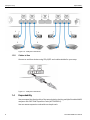
3. Connect the analyzer as shown in the following figure. The following figure shows connections between Port‐pairs P1‐P2 to Device 1 and Device 2; P3‐P4 to Device 3 and Device 4; and so on.
SierraNet M408 User Manual
7
Teledyne LeCroy
Expandability
1
4
2
3
Figure 1.6: Analyzer Connections
1.3.2
Cables to Use
Connect to and from devices using SFP+/QSFP and a cable suitable for your setup. Figure 1.7: Analyzer Connections
1.4
Expandability
You can expand the functionality of the tester by daisy‐chaining multiple SierraNet M408 analyzers with CATC SYNC Expansion Cards (ACC‐EXP‐002‐X).
You can remove expansion cards with two simple tools.
8
SierraNet M408 User Manual
Expandability
1.4.1
Teledyne LeCroy
Removing Expansion Cards
You can remove expansion cards using two tools:
Standard (flat blade) 3/16” screwdriver
Teledyne LeCroy Extraction Tool (part number 230‐0160‐00)
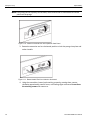
Figure 1.8: Tools needed to Remove the Expansion Cards
Note: The SierraNet M408 Protocol Analyzer does not support the power expansion card shown below. However, the method of inserting and removing any expansion card is the same.
To remove an expansion card, follow these steps:
1. Unplug the system from AC power and turn the system so the expansion port is facing you. Note the two retaining screws and the holes for the extraction tool that are located on the panel of the expansion card.
Holes in the
Expansion Card
Figure 1.9: Holes in the Expansion Card Panel
2. Insert the extraction‐tool prongs into the holes in the expansion card panel.
SierraNet M408 User Manual
9
Teledyne LeCroy
Expandability
Note: If the prongs do not slip easily into the holes, use a small nail file or similar device to remove paint from the prongs
Figure 1.10: Insertion of Handle/Tool into Expansion Card Panel
3. Rotate the extraction tool to a horizontal position to lock the prongs into place and make a handle
Figure 1.11: Rotate Handle/Tool from Vertical to Horizontal
4. Using the screwdriver, loosen both retaining screws by rotating them counter‐
clockwise approximately two full turns, until feeling slight resistance. Do not force the retaining screws after two turns.
10
SierraNet M408 User Manual
Expandability
Teledyne LeCroy
Figure 1.12: Loosen Screws with Flat Bladed Screw Driver
5. Using the extraction tool as a handle, gently wriggle the expansion card forward about 1/8”.
Figure 1.13: Pulling on the Expansion Card
6. Repeat steps 4 and 5 approximately three times, until the card is free from the retaining screws and you can remove the card from the system.
Figure 1.14: Remove Expansion Card from Chassis
SierraNet M408 User Manual
11
Teledyne LeCroy
1.4.2
Expandability
Daisy-Chaining with CATC SYNC Expansion Cards
You can daisy‐chain analyzer units for higher port count, by connecting the units through the optional CATC SYNC Expansion Card on the analyzer back.
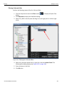
Connecting Two SierraNet M408 Analyzers via the CATC Sync Expansion Card (ACC-EXP002-X)
Multiple SierraNet M408 Analyzers can be connected using their CATC Sync ports which require an optional expansion card (ACC‐EXP‐002‐X).
Note: Refer to relevant protocol analyzer user manual for instructions on how to install the expansion card.
To do so perform the following steps:
1. Make sure to stop any recordings in progress.
Note: You may plug/unplug the sync cable while the analyzer unit is powered on.
2. Connect the female end of the sync cable to the SYNC OUT port of one SierraNet M408.
3. Connect the male end of the sync cable to the SYNC IN port of the other SierraNet M408 (see Figure 1.15 on page 12.)
Figure 1.15: An Example of Connecting two SierraNet M408 Analyzers
12
SierraNet M408 User Manual
Expandability
Teledyne LeCroy
Connecting to Sierra FC M8-4 and Sierra FC M164 Analyzers via the CATC Sync Expansion
Card
You can connect and control any of the following analyzers:
SierraNet M408
SierraNet M168
Sierra FC M8‐4
Sierra FC M164
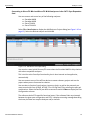
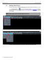
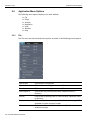
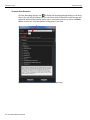
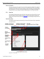
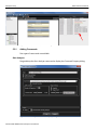
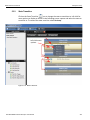
Select File > New Project to display the Add Device to Project dialog (see Figure 1.16 on page 13). Select the desired analyzer and click OK.
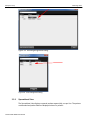
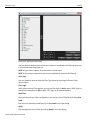
Figure 1.16: Add Device to Project Dialog
You can also create hybrid Ethernet/FC traces when the SierraNet M408 is daisy‐chained with other compatible analyzers.
This is similar to the CrossSync functionality, but is done internal to the application, automatically.
You can connect to any of the off‐line devices to create a dummy project and use the project when you are connected to a device.
You can select a function from Analyzer, Jammer or both, as well as the protocols you want to work with from 10 GigE, 40 GigE, FC or 10 GigE and FC by selecting the port pair combinations. Select the Device you want to connect to and click More to display the Port Configuration columns. The software checks SFP speed for functional ports. If the software finds any mismatch between the given port configuration and SFPs, it displays a warning message describing the issues, but does not stop the Analyzer and/or Jammer. SierraNet M408 User Manual
13
Teledyne LeCroy
Launching Your Analyzer
Figure 1.17: Port Configuration Dialog.
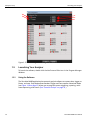
1.5
Launching Your Analyzer
To launch the software, double‐click the Net Protocol Suite Icon in the Program Manager Window.
1.5.1
Using the Software
The SierraNet M408 application has protocol analysis software to capture data, trigger on Events, and save. Easy Mode allows standard Trigger and Data capture. Advanced Mode (see Figure 1.18 on page 15) allows you to program custom triggering, capturing, multi‐
state sequencing, and timers. (See “Protocol Analysis” on page 33.)
14
SierraNet M408 User Manual
Launching Your Analyzer
Teledyne LeCroy
Switch to Advanced Mode Toggle Button
Figure 1.18: Easy/Advanced Mode Toggle Button.
1.5.2
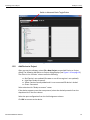
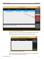
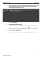
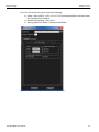
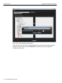
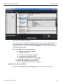
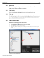
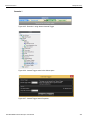
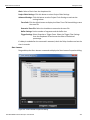
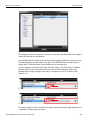
Add Device to Project
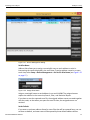
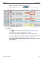
After you start the software, select File > New Project to open Add Device to Project dialog. The following Add Device to Project dialog displays (see Figure 1.19 on page 16). The colors in the ‘Location’ column mean the following:
Red: Device is not updated (firmware or one of bus engines is not updated).
Light Blue: Ready to connect.
Yellow: Device manually added and it is not connected OR device is locked.
Green: Connected
Select a device with “Ready to connect” status.
If the device supports more than one protocol, select the desired protocols from the drop‐down list in the Port column. Select the port configuration from the Link Assignment column.
Click OK to connect to the device.
SierraNet M408 User Manual
15
Teledyne LeCroy
Launching Your Analyzer
Figure 1.19: Add Device to Project Dialog Note: Click Refresh Device List to display all the devices on the on the local Ethernet subnet and also devices connected via USB cable.
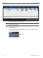
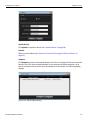
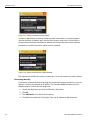
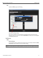
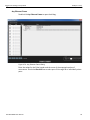
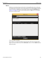
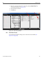
1.5.3
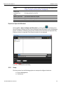
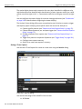
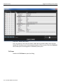
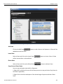
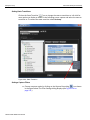
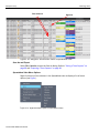
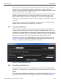
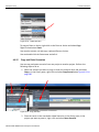
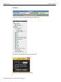
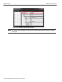
Device Management
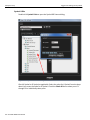
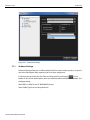
Click on Setup and select Device Management to open the Device Management dialog (see Figure 1.21 on page 17). Figure 1.20: Connecting to Device(s).
16
SierraNet M408 User Manual
Launching Your Analyzer
Teledyne LeCroy
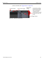
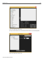
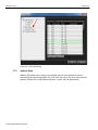
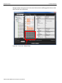
Figure 1.21: Device Management Dialog.
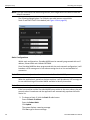
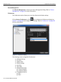
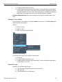
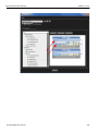
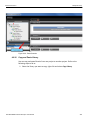
Set Alias Name
Address Alias allows you to assign a meaningful name to each address to assist in interpreting the results displayed in the trace view. To assign address names in an open trace view, select Setup > Device Management > Set Device Alias Name (see Figure 1.22 on page 17.) Figure 1.22: Assign Alias Name.
Assign a meaningful name to each address in use and click OK. The assigned names replace the address in the trace view, Search, filter,. and Statistical Report.
If you elect to save the captured trace file, the assigned address names are saved together with the result, so that when you open the trace file later, the assigned names are retained.
Set As Default
If you want to set these address aliases for trace files that will be captured later, you can set them as default, and new traces will be opened by these default address aliases. SierraNet M408 User Manual
17
Teledyne LeCroy
Launching Your Analyzer
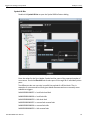
Connect/Disconnect
Click Connect to connect or click Disconnect to disconnect a device.
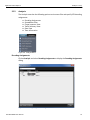
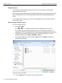
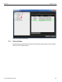
Add Device...
Click Add Device to add a device with a static IP address.
Figure 1.23: Add device.
Note: When entering addresses, you must include the leading zeros. Use 003.010.195.006 as entering 3.10.195.6 will not work. This is also applicable for Figure 1.33 on page 25.
Find
Click the Find button to test if the device at the specified IP address can be located.
Force Add/Connect Attempt
Use this option if the Find function fails, but you're sure the address is correct and you still want to attempt the connection. This setting is stored in the device list database and is applied when attempting to connect to the device.
Remove Device
Click Remove Device to remove a previously added device.
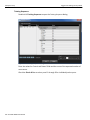
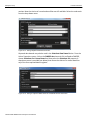
IP Settings
Click IP Setting to reset a device’s IP settings. The following IP Setting dialog displays (see Figure 1.24).
18
SierraNet M408 User Manual
Launching Your Analyzer
Teledyne LeCroy
Figure 1.24: IP Setting Dialog.
Update Device
Click Update to update a device (see “Update Device” on page 28). Subnets
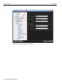
Refer to section below (see “Ethernet Connectivity Through a Different Subnet” on page 22).
Adapters
Click Adapters to select the network adapter to use for connecting to Ethernet‐connected devices. Some PCs have multiple adapters for connecting to different networks, so be sure to choose the one to which your desired device is connected. The following dialog displays.
Figure 1.25: Select Adapter Dialog.
SierraNet M408 User Manual
19
Teledyne LeCroy
Launching Your Analyzer
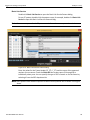
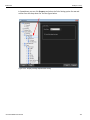
Reset Device
Click Reset Device to open the Reset Device dialog. To Reset a Device, select a Device from the list below or enter an IP address. Then click the Reset button to reset the device.
Figure 1.26: Device Reset Menu
Refresh Device List Click Refresh Device List to refresh the device list.
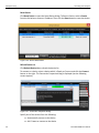
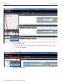
To connect to a device, select a device which is Ready to Connect and click the Connect button on the right. The Connection Properties dialog is displayed (see the following screen capture).
Figure 1.27: Connection Properties Dialog.
Specify one of the actions from the following:
20
Automatically connect to the device
Ask if I want to connect to the device
SierraNet M408 User Manual
Launching Your Analyzer
Teledyne LeCroy
Take no action
If ‘Automatically connect to the device’ is selected, the next time the application opens the device will be automatically connected.
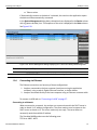
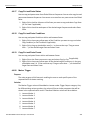
In the Device Management dialog daisy‐chained units are displayed in the Device column with a [ (square bracket) icon. The sequence of the units is displayed in the Order column. See Figure 1.28.
Figure 1.28: Device Management Dialog Displaying Unit 1 and Unit 2 Daisy-Chained together.
Note: When using the CATC Sync cards the order is automatically detected.
IMPORTANT! Power up all units before starting the software.
1.5.4
Connecting via Ethernet
The Ethernet connection can have any of these configurations:
1. Analyzer connected to the host computer (machine running the application software), using a switch, Gigabit Ethernet interface, or similar device. 2. Analyzer connected directly to the host computer using an Ethernet crossover cable. To connect via USB refer to “Connecting Via USB” on page 27.
Connecting to a Network
When connected to a network, the analyzer can communicate with the DHCP server in order to obtain it's IP address configuration. The client needs to send a request to the DHCP server to obtain an IP. The server sends only one reply. The server does not necessarily send the available IP address
The SierraNet M408 product uses the following ports:
TCP Ports: 4000 ‐ 4003
SierraNet M408 User Manual
21
Teledyne LeCroy
Launching Your Analyzer
UDP Ports: 4033‐4035
Connecting using a Switch, or Similar Device
The SierraNet M408 analyzer is automatically detected by the application if the analyzer and the host PC on which the application is running are on the same Ethernet subnet. If the analyzer and the host PC are located on different subnets then the IP address of the analyzer needs to be configured manually in the application. To add the IP address to the Select Device dialog, use the Add Device button (refer to “Add Device...” on page 18 and see Figure 1.24 on page 19). See Figure 1.24 on page 19 to set the IP address.
Analyzer Connected Directly to the Host Machine Using a Crossover Ethernet Cable
SierraNet M408 Systems are designed to connect to host PCs using a network connection, which allows the user to control the SierraNet M408 System from a local or remote host system. When connected to the host machine using a crossover ethernet cable, the Analyzer must be given a static IP address such that it will reside on the same subnet as the Ethernet interface of the host computer. See Figure 1.24 on page 19 to set the IP address. Ethernet Connectivity Through a Different Subnet
The default discovery mechanism relies on broadcast messaging, which typically does not traverse between different subnets. Thus, alternate mechanisms are required to discover devices on different subnets. This section describes two methods: automatic subnet scanning and manual device adding.
Automatic Subnet Scanning
The software can be configured to automatically discover devices on other subnets. To do this, you must specify which subnets you would like the software to scan. This section describes how to add subnets so that the software will scan them for available devices.
22
SierraNet M408 User Manual
Launching Your Analyzer
Teledyne LeCroy
Figure 1.29: Device List with Subnets Button
Clicking on the “Subnets…” button invokes the “Manage Additional Subnets” dialog, which shows the existing subnets and allows the user to add/remove them.
Figure 1.30: Manage Additional Subnets Dialog
Subnets in this list will be saved (e.g. to the Windows registry). Clicking on the “Add…” button invokes a dialog for adding another subnet.
SierraNet M408 User Manual
23
Teledyne LeCroy
Launching Your Analyzer
Figure 1.31: Adding a Subnet with Host’s Mask
A subnet is identified by a network IP address and a subnet mask, so both parameters must be specified. By default, we’ll use the Host’s subnet mask since it’s most likely in enterprise environments that different subnets will still have the same mask. However, the option to provide some other subnet mask is provided.
Figure 1.32: Adding a Subnet With a Different Mask
The software will validate the subnet to make sure it is not the same as the host’s subnet.
Connecting Manually
If the device cannot be discovered through the automatic discovery mechanisms, you can discover it directly if you know its IP address. The SierraNet M408 IP address must be added manually. Perform the following steps:
1.
2.
3.
4.
24
Launch the application and click the Ethernet radio button.
Click OK.
Click Add Device in the Select Device dialog.
The Add Device with Static IP displays. Enter the IP address to add the device.
SierraNet M408 User Manual
Launching Your Analyzer
Teledyne LeCroy
Figure 1.33: Add New Device with Static IP Address
Once the IP address is added, the application will then send a connection request to that IP address to connect to the SierraNet M408 System. Setup IP
This section describes the connectivity procedure for the SierraNet M408 System (see “IP Settings” on page 18).
Configuring the Ethernet Connection
There are two ways of configuring a SierraNet M408 for network connectivity:
DHCP automatically assigns an IP address. DHCP is the default.
Static IP prompts you to enter a specific IP address.
The SierraNet M408 can be configured from the unit itself using the five buttons and the LCD display on the front panel of the analyzer. For additional information, see “LCD Display and Button Functions for Configuring the Analyzer” on page 5. Dynamic Configurations
Dynamic configuration uses DHCP (Dynamic Host Configuration Protocol). Under DHCP, SierraNet M408 will issue a broadcast to any DHCP Server requesting configuration. If a DHCP server is present on the network, it will assign an IP address, Subnet Mask and a default GATEWAY (a router port IP address) to the SierraNet M408. The Gateway port will be used by SierraNet M408 to forward packets to IP addresses that do not reside within the same subnet. When using the dynamic configuration, the front panel display will only update the IP address. The subnet mask and gateway address will remain at the last values programmed (000.000.000.000 by default, or whatever was last programmed in the static configuration). While in dynamic mode, these parameters will have actually been programmed within the IP STACK inside the SierraNet M408, but are not displayed in the LCD display. To change from DHCP to Static IP, you must be connected to a device using USB:
1. Select Setup > All Connected Devices > IP Settings from the menu bar.
SierraNet M408 User Manual
25
Teledyne LeCroy
Launching Your Analyzer
Note: If you are connected to the device using Ethernet, the Configuration menu does not have the Setup IP command.
The IP Setting dialog displays. For IP Mode, two radio buttons are available: Static IP and DHCP. DHCP is the default (see Figure 1.34 on page 26.) Figure 1.34: Static IP Setup Dialog
Static Configurations
Within static configurations, SierraNet M408 must be manually programmed with an IP address, Subnet Mask and a default GATEWAY. Once SierraNet M408 has been programmed with the static network configuration, it will broadcast a UDP message on its own subnet stating that is on line and available for connection. Note: This broadcast is only on the subnet that includes the SierraNet M408 System. When the application is started on the host machine, it will broadcast a UDP message on its own subnet asking all SierraNet M408s available to identify themselves. Note: This broadcast is only on the host machine's subnet. If the host machine and the SierraNet M408 System reside on the same subnet, they will see each other’s broadcasts and the application will automatically populate the Select Device list. 2. To change to Static IP, click the Static IP radio button.
Enter the Static IP Address.
Enter the Subnet Mask. Click Update. The system displays a warning message. Click Yes to get a success message.
26
SierraNet M408 User Manual
Launching Your Analyzer
Teledyne LeCroy
Click OK. The message closes and the device resets. 3. To change back to DHCP, in the IP setup dialog, click the DHCP radio button, then click Update.
Figure 1.35: Dynamic IP Setup Success Message
After you see the Warning Message, click Yes
After you see the Success Message, click OK.
Note: You can also click Reset.
1.5.5
Connecting Via USB
To set up the Analyzer using a USB for the first time: 1.
2.
3.
4.
5.
6.
7.
Remove the Analyzer from its shipping container. Insert the Installation CD. Connect the Analyzer to a power outlet using the provided power cord. Connect the USB port to a USB port on the PC using a USB cable. Turn on the rear power switch and the front power switch. Click Next after you see the Add New Hardware Wizard dialog. Follow the Microsoft® Windows® on‐screen Plug‐and‐Play instructions for the automatic installation of the Analyzer as a USB device on your host machine. (The required USB files are included on the Installation CD.)
8. Click Finish when you see the message that says “Windows has finished installing the software that your new hardware requires” and the file has been installed in your host machine. Note: Do not change from USB to Ethernet, or back, without power cycling the Analyzer.
SierraNet M408 User Manual
27
Teledyne LeCroy
Launching Your Analyzer
To connect the Analyzer to a host system via ethernet, refer to “Connecting via Ethernet” on page 21.
1.5.6
Update Device
The Update Device dialog allows you to update the Firmware and BusEngine components of a connected analyzer. During the update process, the analyzer may reset and/or need to be power‐cycled. Be sure to follow the on‐screen prompts to complete the update process successfully.
1. Click the Update Device button on the Device Management dialog. Figure 1.36: Update Device Dialog with a Bad Device Status
An item whose version is correct has an OK status in a green box. An item whose version is mismatched has a BAD status in a red box.
Note: You can click the ellipses (...) at the end of a file path and name to display an Open dialog, in which you can browse for files.
2. Click the checkbox to the left of an item with BAD status, then click Update Selected to update that item to the correct version.
28
SierraNet M408 User Manual
Launching Your Analyzer
Teledyne LeCroy
Figure 1.37: Update Device Dialog Beginning to Update Status of a Device
After the update, the device should restart. If the software prompts you to power‐cycle the device, do so at this time; then the update will be complete. Otherwise, when the software prompts you that the update is complete, the update process is done and you may continue using the device.
The connection may freeze when the unit reboots after the firmware update. Perform the following steps to recover:
1. Click OK on the error message in the Info dialog.
2. Click Close to close the Device Setup dialog.
3. Click Refresh Device List in the Device Management dialog (see Figure 1.28 on page 21).
4. Click Disconnect.
Figure 1.38: Device Setup Dialog with OK Device Status
Note: Do not shut down or power cycle the analyzer during this process, unless specifically instructed to do so by the application.
SierraNet M408 User Manual
29
Teledyne LeCroy
1.6
Protocol Analyzer
Protocol Analyzer
To use the software for protocol analysis, first select File > New Project for a new project or File > Open to open an existing protocol analysis .gep file. (see “Protocol Analysis” on page 33.) You can also open a .get example file. Example files are in the Examples folder. You can also select File > Recent Projects to open a project you had recently saved.
Note: Select File from the main menu Analyzer Menu Bar or click on the Hide Menubar icon and select File > Open. Clicking the Alt key toggles showing/hiding the Analyzer Menu Bar.
Note: The application prevents the host machine from going into sleep mode to avoid loss of traces.
The software menus and toolbar options are explained in detail in “Software Menus and Toolbar” on page 36.
For more information on Analyzer Settings refer to “Analyzer Settings” on page 49.
1.6.1
Easy and Advanced Modes
The Easy Mode provides the quickest way to configure the analyzer to filter and trigger on events of interest. See “Trigger Filter Settings in Easy Mode” on page 64.
Use Advanced Mode only after you become familiar with the hardware and software and have special needs. To start working with the protocol analyzer and software. For more information on Advanced Mode refer to “Advanced Mode (User‐Defined)” on page 104.
1.6.2
Viewing Captured Data
After data capture, the captured data is in the Viewer, see “Display Manipulation” on page 113. You can display the same data in:
1.6.3
Spreadsheet View: Shows Protocol Fields and Frames by time.
Frame Inspector View: Shows detail information about packet highlighted in Spreadsheet or Packet views.
Traffic Summary View: The Traffic Summary View for each captured signal can be viewed. It displays errors for the whole trace or for a selected range. You can show grid lines, select rows and modify columns.
Data View: The Data View displays information in Hexadecimal and ASCII format.
Preferences
For special work, you can use the Preferences menu to configure Software Settings, Port Alias, Address Alias and Display Settings. (See“Preferences” on page 149.)
30
SierraNet M408 User Manual
InFusion
Teledyne LeCroy
1.6.4
Port Status
You can see an overview of the analyzer's ports in the Analyzer Settings Pane (see “Port Status Pane” on page 58). 1.7
InFusion
The Teledyne LeCroy InFusion™ Error Injector and Traffic Modifier is an error injector and traffic modification tool that allows you to verify real‐world fault handling for SierraFC systems (see “InFusion” on page 163).
1.8
CrossSync Control Panel
The CrossSync Control Panel allows you to select analyzers for synchronization and manage the recording process. It supports a wide combination of Teledyne LeCroy’s flagship analyzers including PCI Express, USB, DDR, Serial ATA (SATA), Serial Attached SCSI (SAS), Fibre Channel (FC) and Ethernet.
CrossSync is Teledyne LeCroy’s analyzer synchronization solution that enables time‐
aligned display of protocol traffic from multiple daisy‐chained analyzers showing packet traffic from multiple high‐speed serial busses. A lightweight software control panel allows users to select analyzers for synchronization and manage the recording process. Captured traffic is displayed using the latest analyzer software (in separate windows) with all the protocol specific search and reporting features.
Captured packets are displayed in separate windows that share a common time scale. Navigating the traffic in either direction will scroll to the same timestamp in a synchronized window. When using the CrossSync option, users can access the full complement of analysis capabilities available within the individual Teledyne LeCroy software. Search, reporting, and decoding all operate normally. This feature is available with the Teledyne LeCroy Net Protocol Suite software application.
1.8.1
Launching the CrossSync Control Panel
Click Start > Programs > LeCroy > CrossSync > CrossSync Control Panel to launch the application.
SierraNet M408 User Manual
31
Teledyne LeCroy
32
CrossSync Control Panel
SierraNet M408 User Manual
Chapter 2
Protocol Analysis
The system performs Protocol Analysis by defining and running an analysis project for both Fibre Channel over Ethernet (FCoE) and Fibre Channel (FC) depending on the Analyzer that you are connected to. A captured trace is saved in a file with the .get extension. An analysis project definition defines what to capture, what the analyzer triggers on, and the memory settings. You can save defined projects as project *.gep files for later use.
After you install the Analyzer software (see “Software Installation” on page 7) and set up the Analyzer (see “Hardware Setup” on page 7), launch the Analyzer software (see “Launching Your Analyzer” on page 14) to display the main window.
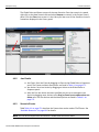
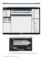
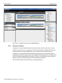
Figure 2.1: Teledyne LeCroy Ethernet Protocol Suite Main Window.
SierraNet M408 User Manual
33
Teledyne LeCroy
2.1
Starting a New Project
Starting a New Project
To start a new project, click File > New Project from the Analyzer menu options, or click on the Hide Menubar icon and select File > New Project (see Figure 2.2) to display the Add Device to Project dialog (see Figure 1.16 on page 13). Select the desired analyzer and click OK.
Note: Click Alt to toggle between showing/hiding the top menu bar.
Figure 2.2: Starting a New Project from the Application Menu bar
Figure 2.3: Starting a New Project from the Menu button on the Application toolbar
34 SierraNet M408 User Manual
Opening an Existing Project
Teledyne LeCroy
The New Project main window opens with default settings to capture Everything on the bus and to Trigger On on Snapshot. (The analyzer captures everything immediately without triggering on anything in particular.)
Figure 2.4: Main Window.
2.2
Opening an Existing Project
To open an existing project, click File > Open from the Analyzer Menu Bar to open an existing .gep project, or click on the Hide Menubar icon 2.3
and select File > Open.
Closing an Existing Project
Close Project allows you to close the current project without closing the Protocol Suite.
SierraNet M408 User Manual
35
Teledyne LeCroy
2.4
Software Menus and Toolbar
Software Menus and Toolbar
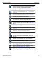
The menu toolbar options are given in the following table.
Open icon. Click to open a file. See “File” on page 38.
Open icon. Click to open a file. See “File” on page 38.
Save icon. Click to save a file. See “File” on page 38.
Preferences icon. Click to save a file. See “Preferences” on page 40.
Spreadsheet View icon. See “Spreadsheet View” on page 118.
Frame Inspector View icon. See “Frame Inspector View” on page 128.
Traffic Summary icon. See “Traffic Summary View” on page 43.
Data View icon. See “Data View” on page 43.
36 SierraNet M408 User Manual
Software Menus and Toolbar
Teledyne LeCroy
Export to Wireshark icon. Click to export trace to Wireshark and launch the Wireshark application. Wireshark must be installed on the PC. Wireshark is a free application available at www.wireshark.org. (see “Export and Open with Wireshark” on page 39).
Displays the Trace information dialog. (see “Trace Information” on page 44).
Find icon. You can search for specific Triggers and specify the From, Domain, Direction and Logic. See “Find” on page 144.
Find Next icon. Searches for the next instance.
Find Previous icon. Searches for the previous instance.
Go to icon. Click to locate cursors or specific packets: Timestamp, X Position, Y Position, Event, Begin, and End. See Figure 2.17 on page 47.
Go to Trigger icon. Click to go to the trigger point in the trace. See Figure 2.17 on page 47.
Go to Marker icon. Click to go to a specific Marker. See “Markers” on page 127.
Zoom in icon. Searches for the previous instance.
Zoom out icon. Searches for the previous instance.
Filter icon. Click to open the filter dialog. See “Filtering” on page 138.
Ports icon. Click to select a port. See “Ports” on page 135.
Idles icon. Click to show/hide idles in a trace. Device External Trig Setting icon. Click to open the Device Settings dialog. See “External Trigger” on page 58. Recording Setting icon. Click to open the Recording Setting dialog. See “Recording Settings Pane” on page 59. Trigger Filter Settings icon. Click to open the Trigger Filter Settings dialog. See “Patterns and Data Capture Setup” on page 71. SierraNet M408 User Manual
37
Teledyne LeCroy
2.5
Application Menu Options
Application Menu Options
The following menu options display in the main window:
2.5.1
File
Setup
Analysis
Navigation
View
Window
Help
File
The File menu has the standard menu options as shown in the following screen capture. Figure 2.5: File Menu Options.
New Project
Open
Save
Save Project as
Save as
Batch
Close
38 SierraNet M408 User Manual
Click to open a new project.
Click to open an existing trace or trace files.
Click to save an existing trace or trace files.
Click to save the current project with a different name or directory.
Click to save an existing trace or trace files with a different name or directory.
Click to run batch scenarios. (see “Batch Scenario” on page 217). Available only after a project is open.
Click to close a frame or window when multiple frames or windows are open.
Application Menu Options
Teledyne LeCroy
Export Export file to Excel, text or export and open with Wireshark (see “Export and Open with Wireshark” on page 39)
Print/Print Preview/Print Setup
Recent Trace Files
Recent Projects
Exit
Printing options for the file
Lists recent trace files to open Lists recent projects to open
Click to exit the application.
Export and Open with Wireshark
Selecting File > Export and Open with Wireshark or clicking the icon displays the Save As Dialog. Checking the Only Export Displayed Events box exports only the displayed events. If the box is unchecked, then all the contents of the trace file are exported. Only Ethernet content is exported; Fibre Channel content is not exported.
Figure 2.6: Wireshark Save As Dialog.
2.5.2
Setup
The Setup menu has the following options to setup and configure the device:
SierraNet M408 User Manual
Device Management
Preferences
39
Teledyne LeCroy
Application Menu Options
Device Management
Click Device Management to display the Device Management dialog. Refer to “Device Management” on page 16 for more information.
Preferences
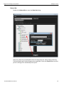
The Preferences option allows you to set the software and display settings. Click on Setup > Preferences or click icon to display the Preferences dialog (see Figure 2.7 on page 40) and configure these settings. Refer to “Preferences” on page 149 for more information.
Figure 2.7: Preferences Dialog.
The following can be configured in Preferences:
Software Settings
Port Alias
Address Alias Display settings User Path
Temp Path
Browse Default Path
Software default
Windows default
FC Backbone Version
BB‐5
BB‐6
40 SierraNet M408 User Manual
Application Menu Options
2.5.3
Teledyne LeCroy
Analysis
The Analysis menu has the following options to view trace files and specify SCSI decoding assignments:
Decoding Assignments
Spreadsheet View
Frame Inspector View
Traffic Summary View
Data View
Trace Information
Figure 2.8: Analysis Menu.
Decoding Assignments
Click on Analysis and select Decoding Assignments to display the Decoding Assignments dialog.
Figure 2.9: Decoding Assignments Dialog.
SierraNet M408 User Manual
41
Teledyne LeCroy
Application Menu Options
Spreadsheet View
Click on Analysis and select Spreadsheet View or click the the Spreadsheet View. icon to display Figure 2.10: Spreadsheet View.
Spreadsheet View displays Protocol Fields and Frames by time. Refer to “Spreadsheet View” on page 118 for more information.
Frame Inspector View
Click on Analysis and select Frame Inspector View or click the Frame Inspector View.
icon to display the Figure 2.11: Frame Inspector View.
Frame Inspector View displays detail information about a frame highlighted in Spreadsheet view. Refer to “Frame Inspector View” on page 128 for more information.
42 SierraNet M408 User Manual
Application Menu Options
Teledyne LeCroy
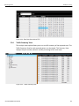
Traffic Summary View
Click on Analysis and select Traffic Summary View or click the Traffic Summary View.
icon to display the Figure 2.12: Traffic Summary View.
The Traffic Summary View for each captured signal can be viewed. This Summary View displays the statistics of commands, the type of command and the total count. For each command it displays the percent of the total count. The software collects up to 10,000 unique pairs for the reports. Anything beyond that is grouped into the "Others" category as shown in Figure 2.12.
Data View
Click on Analysis and select Data View or click the (see Figure 2.13 on page 44).
SierraNet M408 User Manual
icon to display the Data View 43
Teledyne LeCroy
Application Menu Options
Figure 2.13: Data View.
The Data View displays information in Hexadecimal and ASCII format. Refer to “Data View” on page 134 for more information. Trace Information
Click on Analysis and select Trace Information or click the icon to display the trace Information dialog (see Figure 2.14 on page 45 and Figure 2.15 on page 46). You can click on the hyperlinks: File info, Hardware info, Project info or License info to navigate to that section. Click Open Trace Project to open the project in which the trace was captured.
44 SierraNet M408 User Manual
Application Menu Options
Teledyne LeCroy
Figure 2.14: Trace Information Dialog 1.
SierraNet M408 User Manual
45
Teledyne LeCroy
Application Menu Options
Figure 2.15: Trace Information Dialog 2.
2.5.4
Navigation
The Navigation menu option enables the user to navigate the application (see Figure 2.16 on page 47). You can go to the trigger, marker or where the cursor is located. Markers can also be added and removed. Find menu options are available as shown in the screen capture below.
Note: The menu options listed in the Navigation menu can also be selected when you right‐click anywhere on the screen, see “Markers” on page 127.
46 SierraNet M408 User Manual
Application Menu Options
Teledyne LeCroy
Figure 2.16: Navigation Menu Option.
The Navigation menu currently has the following options (see Figure 2.16 on page 47).
Go To menu options allows location of cursors or specific packets: Timestamp, X Position, Y Position, Event, Begin, and End. Refer to Figure 2.17.
Figure 2.17: Navigation Go to Menu Option.
2.5.5
Go to Trigger‐ Allows you to go to the trigger point in the trace.
Go to Marker‐ Allows you to go to specific Marker (see “Markers” on page 127).
Find ‐ Allows you to examine any data capture file to quickly locate the packet or data pattern (see “Find” on page 144).
Find Next ‐ Gives you the option to search for the next instance (see “Find” on page 144).
Find Previous ‐ Gives you the option to search for the previous instance (see “Find” on page 144).
Display Markers ‐ Displays the list of markers (see “Markers” on page 127).
View
The View menu has the following options:
SierraNet M408 User Manual
Zoom in‐ Allows you to zoom in the view.
Zoom out‐ Allows you to zoom out the view.
Hide/Show ‐Displays the Filter dialog box enabling you to configure filters applied to the trace view.
Hide/Show non‐Frames ‐ Shows/Hides the Idles in the trace view.
Toolbars‐Allows you to customize the toolbar display (see Figure 2.18 on page 48).
Menu Bar‐Selecting and deselecting this option toggles between showing and hiding the menu bar. Press the Alt + Windows keys to do the same.
47
Teledyne LeCroy
Application Menu Options
Figure 2.18: View Menu Option.
2.5.6
Window
Window ‐ Allows you to configure your display. It has the following options:
2.5.7
Window Cascade (see “Switching Views” on page 117).
Window Tile (see “Switching Views” on page 117).
Close All Traces ‐ closes all open traces
Help
The Help menu (see Figure 2.19 on page 49) currently has the following options:
Tell Teledyne LeCroy
Report a problem to Teledyne LeCroy Support via e‐mail by selecting Help>Tell Teledyne LeCroy from the application toolbar. This requires that an e‐mail client be installed and configured on the host machine.
Help Topics
Displays the User Manual.
License Information
Displays the License information with the licences that are purchased and their features (see “License Information” on page 160).
Check for Updates
Checks to see if there are any updates available for download “Check for Updates” on page 161.
Shortcut List
Displays a list of keyboard shortcuts (see “Shortcut List” on page 161).
About
Displays the current Net Protocol Suite information, see “About” on page 162.
48 SierraNet M408 User Manual
Analyzer Settings
Teledyne LeCroy
Figure 2.19: Help Menu Option.
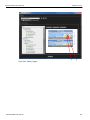
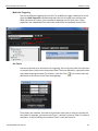
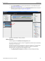
2.6
Analyzer Settings
The Teledyne LeCroy Ethernet Protocol Suite Analyzer Settings panel in the application has six functional sections as shown below. The application is designed such that the user starts from the left pane and moves to the right pane to connect to a device and record a capture as listed below.
1
2
3
4
5
Figure 2.20: Analyzer Settings Panel.
1.
2.
3.
4.
Device Pane: Enables adding and assigning a device.
Port Status Pane: View the port status.
Session Control Pane: Starts and stops recording.
Recording Settings Pane: Manage the recording settings such as Number of Segments and Segment Size.
5. Trigger/Filter Settings Pane: Enables Trigger Filter settings.
2.6.1
Device Pane
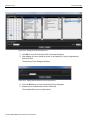
The Device pane allows you to add or remove a device in the chain of attached devices and assign each device to a different project (see Figure 2.21 on page 50). You must first add a device before activating it by clicking Setup > Device Management to select a device drag‐and‐drop it onto a device in the Project Device Pane. You can have multiple projects assigned to different devices. A single project will automatically connect to an active device. Right‐click on a device and select Activate to start the device. Click The X icon to disconnect the device.
SierraNet M408 User Manual
49
Teledyne LeCroy
Analyzer Settings
Click the + sign to add a device.
Click the x sign to remove a device.
1
Click the icon to display the Device Settings dialog.
Click any of the ports to start/stop a session.
2
Click the arrow to toggle Hover the cursor between hiding and showing the devices.
over the analyzers to display port configurations.
Hover the cursor over the ports to display tooltip.
Figure 2.21: Device Pane Displaying Multiple Devices.
Presents a physical representation of the analyzers.
Presents a logical representation of the analyzers.
Perform the following steps to add a device.
1. Click Setup > Device Management.
The Device Management dialog displays.
2. Click on the selected Device (Sierra Net M408 SN: 10884) and select the Connect button.
50 SierraNet M408 User Manual
Analyzer Settings
Teledyne LeCroy
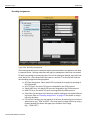
Device Settings
The Device Settings dialog allows you to configure Probe Calibration and the External Trigger settings for each device. See “Probe Calibration” on page 51 and “External Trigger” on page 58 for more information.
2.6.2
Probe Calibration
In the Device Settings dialog, select the Probe Calibration Settings tab. Depending on the project's protocol configuration, the Device Settings tab appears slightly different. These settings are meant for advanced users to tune the performance of the Analyzer's receiver ports, the Jammer's receiver and transmitter ports, and the Analyzer's DUT link pass‐
through path. In most cases, the default settings will perform well and should be used as‐
is.
40 GigE Configurations
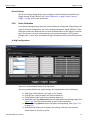
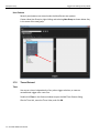
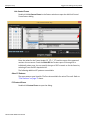
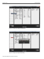
Figure 2.22:
Device Settings dialog for 40 GigE device.
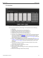
You can manually calibrate the probe settings. Set the parameters for the following:
SierraNet M408 User Manual
Cable Type: Select Optical, 1m Copper or 3m Copper.
RX Eq DC gain: Select a value from the drop‐down list.
RX Eq Control: Select a value from the drop‐down list.
Advanced: Selecting Advanced displays the Advanced Probe Setting dialog. (See Figure 2.23.) Enter the desired values for each of the parameters. Splitter: Selecting Splitter displays the Splitter Settings dialog. (See Figure 2.24 on page 52.) Apply Selected Settings to All: Applies the settings selected in the currently selected port to all ports in the list.
51
Teledyne LeCroy
Analyzer Settings
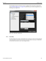
Import: Loads calibration settings from *.csv file.
Export: Creates a new *.csv file.
Set as Bootup: Loads these settings into memory; rebooting will automatically load these values.
Restore Factory Settings: Restores factory settings.
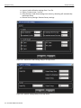
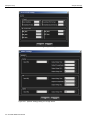
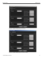
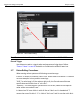
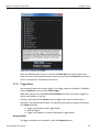
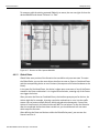
Figure 2.23:
Advanced Probe Setting dialog for 40 GigE device.
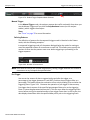
Figure 2.24:
Splitter Settings dialog for 40 GigE device.
52 SierraNet M408 User Manual
Analyzer Settings
Teledyne LeCroy
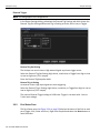
10 GigE Configurations
Figure 2.25:
Device Settings dialog for 10 GigE device.
You can manually calibrate the probe settings.
Set the parameters for the following:
Cable Type: Select Optical, 1m Copper or 3m Copper.
RX Eq DC gain: Select a value from the drop‐down list.
RX Eq Control: Select a value from the drop‐down list.
Advanced: Selecting Advanced displays the Advanced Probe Setting dialog. (See Figure 2.26.) Enter the desired values for each of the parameters. Splitter: Selecting Splitter displays the Splitter Settings dialog. (See Figure 2.27 on page 54.) Apply Selected Settings to All: Applies the settings selected in the currently selected port to all ports in the list.
Import: Loads calibration settings from *.csv file.
Export: Creates a new *.csv file.
Set as Bootup: Loads these settings into memory; rebooting will automatically load these values.
Restore Factory Settings: Restores factory settings.
SierraNet M408 User Manual
53
Teledyne LeCroy
Analyzer Settings
Figure 2.26:
Advanced Probe Setting dialog for 10 GigE device.
Figure 2.27:
Splitter Settings dialog for 10 GigE device.
54 SierraNet M408 User Manual
Analyzer Settings
Teledyne LeCroy
FC Configurations
Figure 2.28:
Device Settings dialog for FC devices.
You can manually calibrate the probe settings. Set the parameters for the following:
Cable Type
RX Eq DC gain: Select value from the drop‐down list.
RX‐8G Eq DC gain: Select value from the drop‐down list.
RX Eq Control: Select value from the drop‐down list.
RX‐8G Eq Control: Select value from the drop‐down list.
Advanced: Selecting Advanced displays the Advanced Probe Setting dialog with the RX/TX tab selected. (See Figure 2.29.) Enter the desired values for each of the parameters. Select the RX/TX 8G tab (see Figure 2.30 on page 56) and enter the desired values for each of the parameters.
Splitter: Selecting Splitter displays the Splitter Settings dialog. (See Figure 2.31 on page 57.) Enter the desired values for each of the parameters. Select the 8G tab (see Figure 2.32 on page 57) and enter the desired values for each of the parameters. Apply Selected Settings to All: Applies the settings selected in the currently selected port to all ports in the list.
Import: Loads calibration settings from *.csv file.
Export: Creates a new *.csv file.
Set as Bootup: Loads these settings into memory; rebooting will automatically load these values.
Restore Factory Settings: Restores factory settings.
SierraNet M408 User Manual
55
Teledyne LeCroy
Analyzer Settings
Figure 2.29:
Advanced Probe Setting dialog for FC device - RX/TX tab.
Figure 2.30:
Advanced Probe Setting dialog for FC device - RX/TX 8G tab.
56 SierraNet M408 User Manual
Analyzer Settings
Teledyne LeCroy
Figure 2.31:
Splitter Settings dialog for FC device.
Figure 2.32: Splitter Settings dialog for FC device - 8G tab.
SierraNet M408 User Manual
57
Teledyne LeCroy
Analyzer Settings
External Trigger
Note: This dialog applies to all configurations.
In the Device Settings dialog, selectelect the External Trig Settings tab which shows the External Trig Out Setting and External Trig In Setting as Active, Active Low, or Toggle.
Figure 2.33: External Trigger Settings dialog.
External Trig Out Setting
The Analyzer can send a Low or High external signal any time a trigger occurs. Select the External Trig Out Setting: High Active, Low Active, or Toggle from High to Low or Low to High once (3.3 V output).
Enter the External TrigOut pulse width.
External Trig In Setting
An external Low or High input signal can cause triggering. Select the External Trig In Setting: High Active, Low Active, or Toggle from High to Low or Low to High once (3.3 V output).
The nominal External Trigger voltage is 0.818 volts. Trigger In can work with 1 volt to 5 volts input voltage.
2.6.3
Port Status Pane
The Port Status pane (see Figure 2.34 on page 59) displays the status of the link on each port (Trigger, Link, Frame and Error). Right‐click the pane and select the Reset button to reset the status. 58 SierraNet M408 User Manual
Analyzer Settings
Teledyne LeCroy
Figure 2.34: Port Status Pane.
2.6.4
Session Control Pane
Use the Session Control pane (see Figure 2.35 on page 59) to run and stop a capture. You can also set the idle. Start/Stop Session Button before recording is started
Start/Stop Session Button after recording is started
Figure 2.35: Session Control Pane.
Disabling a port can be used to save recording buffer space. A disabled port can still trigger the analyzer.
Auto Speed is the default port speed selection. It will automatically detect and display the line speed. In rare cases (such as debugging speed negotiation), it might be desired to set the analyzers speed manually. Note, that when the speed is set manually, traffic at different speeds will not be captured correctly. When “Trace is Not Saved” is displayed, this means that the trace is opened for viewing in Quick View mode, but it has not been saved to disk yet.
2.6.5
Recording Settings Pane
Use the Recording Settings (see Figure 2.36 on page 59) pane to select and set the number and size of segments and save a new trace file. (See “Buffer Size and Segments” on page 103.) Slider
Click to display the Recording Settings dialog
Figure 2.36: Recording Settings Pane.
SierraNet M408 User Manual
59
Teledyne LeCroy
Analyzer Settings
Protocol Error Detection
Click the Recording Settings icon to display the Recording Settings dialog. It has three tabs. In the GE 10G PE Detection Tab you can select which Protocol Errors the analyzer will show and which will be ignored. Select one or more protocol errors or select the Check All box to select all. Enter the Number of Segments in the field. Figure 2.37: GE 10G PE Detection Tab - Recording Settings Dialog.
60 SierraNet M408 User Manual
Analyzer Settings
Teledyne LeCroy
In the FC 16G Setting Tab you can select the following:
Speed ‐ select 1.0625, 2.125, 4.25. 8.5, 16.0 and Autospeed from the drop‐down list. Autospeed is the default.
Disable Descrambling ‐ select ports.
Training Signal Pack Mode ‐ Unpacked and Packed.
Figure 2.38: FC 16G Setting Tab - Recording Settings Dialog.
SierraNet M408 User Manual
61
Teledyne LeCroy
Analyzer Settings
In the FC 16G PE Detection Tab, you can select which Protocol Errors the analyzer will show and which will be ignored. Select one or more protocol errors or select the Check All box to select all. Enter the Number of Segments in the field. Figure 2.39: FC 16G PE Detection Tab - Recording Settings Dialog.
2.6.6
Trigger/Filter Settings Pane
Use the Trigger/Filter Settings pane to select Snapshot or Event Trigger mode and choose the Trigger Filter settings. The default mode is Snapshot. See “Trigger Filter Settings in Easy Mode” on page 64 for more information.
You can configure the following settings from this dialog:
Select New from the dropdown menu to create new trigger filter settings. The Trigger Filter Settings dialog displays a name adding a new sequential Trigger Fil‐
ter Setting. You can change the default name by typing a new name. Select Manage from the dropdown menu to manage the trigger filter settings (Choosing the Event Trigger option enables Trigger Position to set it manually. You can set the trigger position in the captured buffer as a percentage of the segment size. Trigger point of 0% means the trigger point will be on the first 62 SierraNet M408 User Manual
Analyzer Settings
Teledyne LeCroy
packet in the buffer. (See “Trigger Position” on page 103.) Snapshot Mode
Click for Event Trigger
Trigger/Filter Settings
Arrows allow scrolling through projects when two or more projects are open, and the project has been resized
to minimize screen real
estate.
Set Trigger Position
Figure 2.40: Trigger/Filter Settings Pane.
SierraNet M408 User Manual
63
Teledyne LeCroy
2.7
Trigger Filter Settings in Easy Mode
Trigger Filter Settings in Easy Mode
Easy mode allows you to operate the analyzer with minimum setup. In this mode, you can perform only a Trigger and Data capture. Use Easy Mode to get a comprehensive overview of your analyzer’s capabilities.
The Trigger and Filter settings dialog allows you to set the parameters for triggering on selected triggers and filtering in (including) or filtering out (excluding) selected patterns. The dialog box opens with default settings to capture everything on the bus. The analyzer captures everything immediately without triggering on anything in particular.
2.7.1
Trigger Tab
You can drag and drop patterns from the Trigger Library pane into the Active Pane. You can select the pattern and use the Add and Remove arrows to move patterns between the Patterns Library and the Active pane (see Figure 2.41 on page 64). See “Trigger Setup” on page 101. You can copy a frame from the spreadsheet view and paste it in the Active Pane for triggering.
Click the + icon to
use previously set
Trigger Filter
Settings
Click the X icon to
delete
previously set
Trigger Filter Settings
Include and Exclude arrows
Figure 2.41: Trigger Settings Dialog.
64 SierraNet M408 User Manual
Click this
icon to Rename
Current Trigger
Capture Setting
Trigger Filter Settings in Easy Mode
Teledyne LeCroy
Choose a Parameter
To choose a parameter for capture from any of these categories, highlight the category in the parameter window and click the +>> button to add the selection. You can also drag and drop a pattern. This opens selection dialogs for each of the categories displaying all of the parameters for that category. All patterns added appear in the Project Overview.
2.7.2
Filter Tab
You can drag and drop patterns from the Filter Library pane into the Active Pane. You can select the pattern and use the Add and Remove arrows to move patterns between the Patterns Library and the Active pane (see Figure 2.42). The following filtering options are available:
Capture Everything
Checking this option captures everything on the bus and the Pattern Library is greyed out (see figure below).
Click the + icon to use
previously set triggers
Click the x icon to delete
previously set triggers
Click this
icon to Rename Current Trigger
Capture
Everything
Filter In
Selected Patterns
Filter Out
Selected
Patterns
Always Filter
Out
Auto Negotiation
Truncate
Payload
Include and Exclude arrows
Figure 2.42: Filter Dialog.
SierraNet M408 User Manual
65
Teledyne LeCroy
Trigger Filter Settings in Easy Mode
Filter in Selected Patterns
Checking this option includes the selected patterns in the trace capture (see Figure 2.42 on page 65).
Filter Out Selected Patterns
Checking this option excludes the selected patterns in the trace capture (see Figure 2.42 on page 65).
Always Filter Out
Check one or more option to exclude Idles and or P1 through P8 in the trace capture (see Figure 2.42 on page 65). Note: Capturing a full buffer requires you to capture the traffic with all ports. Using four ports allows you to capture only half the system memory. The size of the system memory is based on the license purchased.
Auto Negotiation
Check this box to always filter out Auto Speed Negotiation traffic. (see Figure 2.42 on page 65). Truncate Payload
Check this option to truncate payload after x‐number of Dword(s) (see Figure 2.42 on page 65). Note: For iSCSI packets, payload truncation may not truncate at the specified value as some packets could come out of sequence.
Run Hardware
To get an immediate overview of the bus traffic to and from your Analyzer, click the Start Session button. Recording Progress
The analyzer begins filling the defined memory buffer with traffic on the bus. After the traffic fills the memory buffer, the traffic is uploaded to the viewer. As recording progresses, the Session Controller indicator changes to reflect the recording progress graphically:
A red vertical line illustrates the location of the Trigger Position you selected in Trigger and Filter Settings.
Pre‐Trigger progress is indicated by Waiting for Trigger in the field to the left of the Trigger Position. Figure 2.43: Pre-Trigger.
66 SierraNet M408 User Manual
Trigger Filter Settings in Easy Mode
Teledyne LeCroy
After the trigger occurs Recording is displayed in the field to the left of the Trig‐
ger Position indicating the progress of the recording. Figure 2.44: Post-Trigger.
When recording is complete Uploading is displayed indicating the progress of the data upload to the host machine.
Figure 2.45: Uploading.
The Recorded Data file appears in the main display window. Save the file for later use by selecting File > Save.
When a captured trace is not saved and the USB cable is removed, the software displays an error message that unsaved traces will be closed. If the user ignores the message, and again plugs in and unplugs the USB cable, the software might get into an unstable state. When the Ethernet cable is removed, the application detects the event after a delay of approximately 2.5 to 3 minutes. During this delay the device status remains ready and an attempt to capture a trace might result in error messages such as :" PCI configuration failed", or " HAL error". If this occurs, you need to power cycle the analyzer to allow detecting the device in the device list and continue capturing. Note: Spreadsheet View is the default display. However, you can view results in any of the different views by selecting View on the menu bar and choosing the desired View. The software remembers the last view (or views combination) used, and will automatically use that next time it is launched.
Data direction arrows
X,Y, T Cursors
Figure 2.46: Typical Spreadsheet View Results Display.
SierraNet M408 User Manual
67
Teledyne LeCroy
Trigger Filter Settings in Easy Mode
The results display shows each transaction for every layer identified in a different color and the data direction identified with data direction arrows. Upstream traffic has a solid yellow arrow from right to left:. Downstream traffic has a solid grey arrow left to right: .
You can configure the viewer display for test and viewing preferences (see “Preferences” on page 149 for details about configuring the viewer display).
The Analysis Project dialog offers you a comprehensive set of choices to create a trigger and capture project satisfying some specific need. You can set the Analyzer to:
Capture specific patterns (see “Patterns and Data Capture Setup” on page 71).
Capture different patterns pre‐ and post‐trigger (see “Patterns and Data Capture Setup” on page 71).
Exclude parameters from capture (see “Patterns and Data Capture Setup” on page 71).
Trigger on a pattern or sequence of patterns (see “Trigger Setup” on page 101).
Configure trace capture memory Select file to save trace capture in memory Saving a Trace Capture
You can save a Trace Capture for review at a later time using the Save As dialog. Figure 2.47: Save As Dialog.
You can limit the range of the saved file. You can save:
All Packets
68 SierraNet M408 User Manual
Trigger Filter Settings in Easy Mode
Teledyne LeCroy
A range between selected cursors
A range between selected level of decoding. The levels allowed are dependent on the traffic in the trace. A trace with only Switch traffic might have the follow‐
ing levels available: ELS Cmd, Frame, GS Cmd, Sequence and SW Cmd, whereas a read‐write trace might have Frame, SCSI Cmd and Sequence available. Only Save Displayed Events: Click the checkbox to save only the Filtered in data in the trace.
Exporting a Trace Capture
You can export a Trace Capture by using the Export menu Option. Click File > Export and select from the three options.
You can:
Export to Excel
Export to Text Export and Open with Wireshark
Figure 2.48: Export Dialog.
You can limit the range of the saved file. You can save:
All Packets
A range between selected cursors
A range between selected level of decoding. The levels allowed are dependent on the traffic in the trace. Project File Types
Projects have the following file types:
SierraNet M408 User Manual
*.gep Protocol Analyzer/Capture Project/Viewer file
*.get Trace file
*.xml Workspace file in Preferences
69
Teledyne LeCroy
Trigger Filter Settings in Easy Mode
Example Projects
The Analyzer includes example projects that you can use to perform an immediate analysis without any setup.
The Analyzer system software has a pre‐defined folder (directory) structure for storing all files. All example files are in the Examples folder under the SierraNet M408 Analyzer folder.
It is strongly recommended that you open some example files to see types of projects that you can create.
Run an Example Analysis Project
To run an example project:
1. Select File > Open.
For Windows XP use ‐ ROOT:\Program Files\LeCroy\Ethernet Protocol Suite
For Windows Server2003 (32 bit), Windows Server 2012 (64 bit), Windows 7 or Windows 8 ‐ ROOT:\Users\Public\Public Documents\LeCroy\Ethernet Protocol Suite
2. Locate example analysis projects by looking in the Examples folder. Traces are available and Traces. Click Data > Examples > Traces.
3. In the Traces folder, choose an example *.get file and click Open to display the example project dialog.
Figure 2.49: Open File Dialog.
4. Click the Open button to execute the pre‐defined trace.
70 SierraNet M408 User Manual
Trigger Filter Settings in Easy Mode
Teledyne LeCroy
5. After the project runs, you see an analyzer trace capture display (see Figure 2.50 on page 71).
Figure 2.50: Analyzer Trace Capture Display.
For details about the results display, see “Display Manipulation” on page 113 and see “Preferences” on page 149.
2.7.3
Patterns and Data Capture Setup
You can refine data capture by choosing Pattern and then selecting specific patterns for capture. Additionally, you can define a different set of patterns to capture after trigger.
The Trigger and Filter settings dialog allows you to set the parameters for triggering on selected triggers and filtering in (including) or filtering out (excluding) selected patterns. Refer to “Trigger Filter Settings in Easy Mode” on page 64.
2.7.4
Pre- and Post Trigger Data Capture
Move the Trigger Position slider button (see Figure 2.40 on page 63) to define one set of patterns for capture prior to the occurrence of a trigger (left of the slider) and another set of patterns for capture after the occurrence of a trigger (right of the slider). The selection and setup procedure is the same for both Pre‐Trigger capture and Post‐Trigger capture. (see “Trigger Setup” on page 101).
2.7.5
Triggering/Filtering Patterns (Easy Mode)
The application provides User Patterns and a library of Preset patterns.
SierraNet M408 User Manual
71
Teledyne LeCroy
Trigger Filter Settings in Easy Mode
User Patterns
Recently used patterns are stored under the Most Recent user pattern.
Create a New User Group by right‐clicking and selecting New Group as shown below. Key in the name of the new group.
Figure 2.51: Creating a New User Group.
2.7.6
Timers/External
Timer
You can set a timer independently of any other trigger selection, to cause an unconditional trigger after a set time.
Double‐click Timer in the Pattern window to open the Add Timer Pattern dialog. Check a Time Unit, enter the Timer Value, and click OK.
72 SierraNet M408 User Manual
Trigger Filter Settings in Easy Mode
Teledyne LeCroy
Figure 2.52: Timer Pattern Dialog.
Note: The timer resolution is limited to one DWORD. The minimum value is 12‐13 DWORD.
External Trigger
Use this event to wait for a signal on the analyzers external trigger input. Refer to “External Trigger” on page 58 for details on configuring the external trigger input.
2.7.7
Pattern Editing Conventions
When entering values in patterns the following conventions apply:
In Binary, 'X' means one bit which is "don't care" and the value can be either 1 or 0. Below are some examples in binary and their meanings: "X10": The value length is 3 bits and from right to left, the first and second bits have specific values and the third one is "don't care". "XXXXXXX1": The value length is 8 bits and from right to left, the first bit has a specific value and the rest are "don't care". In Hexadecimal 'X' means 4 bits in which all four are "don't care". In hexadecimal '?' means either one of the bits 1, 2, 3 or 4 bits is "don't care" and it is not clear which bit is SierraNet M408 User Manual
73
Teledyne LeCroy
Trigger Filter Settings in Easy Mode
"don't care" and which ones have specific value. Some examples are given in the table below.
Hexadecimal Value
Length in bits
"X1"
"X?"
"?X"
"?"
"?"
"7" "7?"
8 bits
8 bits
8 bits
2 bits
3 bits
3 bits
8 bits
Equivalent Value in Binary
"XXXX0001"
"XXXXXX10" "110XXXXX" "XX" "11X" "111"
"01110XX1"
If VI_READ_RQST is selected, the value for the "Device HDR" field will be "10" in binary format as this field is a two‐bits field. This field is the last field in the "DF_CTL" field which is an 8 bits field. For this specific frame, the value of "DF_CTL" will be "XXXXXX10" in binary format and "X?" in hexadecimal format according to the conventions above. 2.7.8
Ethernet Patterns
Basic
Loss of Sync
Double‐click Loss of Sync to open the Loss of Sync Pattern dialog.
Figure 2.53: Loss of Sync Pattern Dialog
This event detects loss of sync on the Ethernet physical layer receiver. Enter the count of the expected number of occurrences. Check the Check All box to select ports P1 through P8 or individually select ports.
Symbol
Double‐click Symbol to open the Symbol Pattern dialog. 74 SierraNet M408 User Manual
Trigger Filter Settings in Easy Mode
Teledyne LeCroy
Figure 2.54: Symbol Pattern Dialog
Enter the values for the Sync Header, Order Set and the count of the expected number of occurrences. Check the Check All box to select ports P1 through P8 or individually select ports.
Two different order sets can exist in one 64 bits payload of a 66 bits block. The six examples of a remote and local fault given below demonstrate how to manually enter ordered set triggers. 0x0100000001000055 ‐> local fault‐local fault
0x000000000100004b ‐> local fault‐idle
0x010000000000002D ‐> idle‐local fault
0x0200000002000055 ‐> remote fault‐remote fault
0x000000000200004b ‐> remote fault‐idle 0x020000000000002D ‐> idle‐remote fault
Auto Negotiation
Double‐click Auto Negotiation to open the Auto Negotiation Pattern dialog. SierraNet M408 User Manual
75
Teledyne LeCroy
Trigger Filter Settings in Easy Mode
Figure 2.55: Auto Negotiation Pattern Dialog
Enter the values for the Data, Code Word, Manchester and the count of the expected number of occurrences. Check the Check All box to select ports P1 through P8 or individually select ports.
76 SierraNet M408 User Manual
Trigger Filter Settings in Easy Mode
Teledyne LeCroy
IPG
Double‐click IPG to open the IPG dialog. Figure 2.56: IPG Pattern Dialog
Enter the IPG Length from the drop‐down list and Bytes values and the count of the expected number of occurrences. Check the Check All box to select ports P1 through P8 or individually select ports.
FCoE Patterns
Basic
Basic Link Service
For any Ethernet pattern, double‐click the pattern name, for example, double‐click Basic Link Service to open the Basic Link Service Pattern dialog. Note: Some screen captures for the Ethernet patterns are similar to the screen capture shown below.
SierraNet M408 User Manual
77
Teledyne LeCroy
Trigger Filter Settings in Easy Mode
Figure 2.57: Basic Link Service Pattern Dialog
Enter the values for the Ethernet header, FCoE header, Frame header and the count of the expected number of occurrences. Check the Check All box to select ports P1 through P8 or individually select ports. Check the Trigger on given pattern with variable header length box to automatically adjust the offset, if optional headers like VLAN tag, VNTag, etc. are present. Uncheck it, to trigger for a pattern at a specific offset from the start of the frame.
Note: Some patterns have additional options to select from drop‐drown lists as shown in the figure above.
Link Control Frame
For any FCoE pattern, double‐click the pattern name, for example, double‐click Basic Link Service to open the Basic Link Service Pattern dialog. Note: Some screen captures for the FCoE patterns are similar to the screen capture shown below.
78 SierraNet M408 User Manual
Trigger Filter Settings in Easy Mode
Teledyne LeCroy
Figure 2.58: Link Control Frame Pattern Dialog
Enter the values for the Ethernet header, FCoE header, Frame header and the count of the expected number of occurrences. Check the Check All box to select ports P1 through P8 or individually select ports.
Check the Trigger on given pattern with variable header length box to automatically adjust the offset, if optional headers like VLAN tag, VNTag, etc. are present. Uncheck it, to trigger for a pattern at a specific offset from the start of the frame.
The following additional Ethernet patterns are available:
FCP Patterns
Frame Information Unit
SCSI
Any SCSI Command
6‐Byte Any SCSI Cmd
10‐Byte Any SCSI Cmd
12‐Byte Any SCSI Cmd
16‐Byte Any SCSI Cmd
Long LBA 16‐Byte Any SCSI Cmd
Variable Length Any SCSI Cmd
Variable Length for Long LBA 32‐Byte Any SCSI Cmd
SPC4
SBC3
MMC6
SMC2
SSC2
OSD2
SierraNet M408 User Manual
79
Teledyne LeCroy
Trigger Filter Settings in Easy Mode
ADC3
FCP Task Management
ELS Patterns
ELS Request
ELS Reply GS Patterns
Generic Link Service‐Request
GS Reply
GS_RJT GS Accept
FC‐SW‐5
Event Service
Key Distribution Service
Alias Service
Management Service Fabric Configuration Service
Unzoned Name Server
Fabric Zone Server
Reserved for Performance Server
Security Policy Server
Security Information Server
Fabric Device Management Server
Time Service
Directory Service ‐ Name Server
Directory Service ‐ FC‐4 Specific Servers
SW Patterns
SW Request
SW Reply FICON Patterns
FCAE Patterns
FCAE_ASM
FCAE‐1553
FCVI Patterns
FCAV Patterns
VSAN Patterns (all FC patterns listed above are available under VSAN as well)
80 SierraNet M408 User Manual
Trigger Filter Settings in Easy Mode
Teledyne LeCroy
FIP Patterns
For any FIP pattern, double‐click the pattern name, for example, double‐click Discovery Solicitation from ENode to open the dialog. Note: All the screen captures for the FIP patterns are similar to the screen capture shown below.
Figure 2.59: FIP Discovery Solicitation from ENode Pattern Dialog
Enter the values for the Ether header, FIP Header and the count of the expected number of occurrences. Check the Check All box to select ports P1 through P8 or individually select ports.
The following FIP patterns are available:
SierraNet M408 User Manual
Discovery Solicitation from ENode
Discovery Solicitation from FCF
Discovery Advertisement
FIP FLOGI Request
FIP FLOGI LS_ACC
FIP FLOGI LS_RJT
FIP NPIV FDISC Request
FIP NPIV FDISC LS_ACC
FIP NPIV FDISC LS_RJT
FIP Fabric LOGO
FIP Fabric LOGO LS_ACC
FIP Fabric LOGO LS_RJT
FIP ELP Request
FIP ELP SW_ACC
FIP ELP SW_RJT
FIP Keep Alive
81
Teledyne LeCroy
Trigger Filter Settings in Easy Mode
FIP Clear Virtual Links‐5DWORD Descriptor
FIP VLAN Request‐2DWORD Descriptor
FIP VLAN Notification
MPCP Pattern
Double‐click Multi control Protocol Frame to open the dialog. Figure 2.60: Multi control Protocol Frame Pattern Dialog
Enter the values for the Ether header and the count of the expected number of occurrences. Check the Check All box to select ports P1 through P8 or individually select ports.
Address Resolution Protocol Pattern
Double‐click Address Resolution Protocol to open the dialog. 82 SierraNet M408 User Manual
Trigger Filter Settings in Easy Mode
Teledyne LeCroy
Figure 2.61: ARP Frame Dialog
Enter the values for the Ether header, ARP Packet and the count of the expected number of occurrences. Check the Check All box to select ports P1 through P8 or individually select ports.
Link Layer Discovery Protocol Pattern
Double‐click LLDP Frame to open the dialog. Figure 2.62: LLDP Frame Dialog
SierraNet M408 User Manual
83
Teledyne LeCroy
Trigger Filter Settings in Easy Mode
Enter the values for the Ether header, LLDPDU TLV and the count of the expected number of occurrences. Check the Check All box to select ports P1 through P8 or individually select ports.
Internet Protocol Pattern
Double‐click Any IP Frame to open the dialog. Figure 2.63: IP Frame Dialog
Enter the values for the Ether header, IP Header and the count of the expected number of occurrences. Check the Check All box to select ports P1 through P8 or individually select ports.
Other Internet Protocol patterns available are:
IP Frame (ICMP)
IP Frame (IGMP)
IP Frame (IPV6)
IP Frame (OSPF)
IP Frame (AH)
IP Frame (ESP)
IP Frame (PIM)
IP Frame (UDP)
IP Frame (TCP)
iSCSI Pattern
Initiator PDU
Double‐click iSCSI Data‐Out to open the dialog. 84 SierraNet M408 User Manual
Trigger Filter Settings in Easy Mode
Teledyne LeCroy
Figure 2.64: iSCSI Data-Out Dialog
Enter the values for the Ether header, IP Header and the count of the expected number of occurrences. Check the Check All box to select ports P1 through P8 or individually select ports.
Other ISCSI patterns available are:
iSCSI Login Request
iSCSI Logout Request
iSCSI NOP‐Out
iSCSI SNACK Request
iSCSI Task Mgmt Request
iSCSI Text Request
Target PDU
The dialogs are similar to the Initiator PDU above. The patterns available are:
SierraNet M408 User Manual
iSCSI Asynchronous Message
iSCSI Response
iSCSI Data‐In
iSCSI Login Response
iSCSI Logout Response
iSCSI Nop‐In
iSCSI Ready to Transfer
iSCSI Reject
iSCSI Task Mgmt Request
iSCSI Text Request
85
Teledyne LeCroy
Trigger Filter Settings in Easy Mode
ISCSI Cmd
Any SCSI Command
Double‐click 6‐Byte Any SCSI Cmd to open the dialog. Figure 2.65: 6-Byte Any SCSI Cmd Dialog
Enter the values for the Ether header, IP Header and the count of the expected number of occurrences. Check the Check All box to select ports P1 through P8 or individually select ports.
Other ISCSI patterns available are:
10‐Byte Any SCSI Cmd
12‐Byte Any SCSI Cmd
16‐Byte Any SCSI Cmd
Long LBA16‐Byte Any SCSI Cmd
Variable Length Any SCSI Cmd
Variable Length For Long LBA 32‐Byte Any SCSI Cmd
SPC4
SBC3
MMC6
SMC2
SSC2
OSD2
ADC3
iWARP Patterns
You may set patterns for the following iWARP RDMA operations:
86 SierraNet M408 User Manual
Trigger Filter Settings in Easy Mode
Teledyne LeCroy
Write
Read Request
Read Response
Send
Send with Invalidate
Send with SE
Send with SE and Invalidate
Terminate
VLAN Patterns
All Ethernet Patterns are available as VLAN Patterns as well. The only difference is that the Ethernet Type of the Ethernet header will be preset to "VLAN", and you should specify the VLAN id value in the VLAN Tag header.
VXLAN Patterns
All Ethernet Patterns are available as VXLAN Patterns as well. The only difference is that the frame will be preset as an IP/UDP frame with the UDP destination port set to "VXLAN", and you should specify the VXLAN Network Id in the VXLAN header.
ISL Patterns
FCoE
All the ISL FCoE patterns are similar to Ethernet patterns. Refer to “FCoE Patterns” on page 77.
FIP
All the ISL FIP patterns are similar to FIP patterns. Refer to “FIP Patterns” on page 81.
MPCP
All the ISL MPCP patterns are similar to MPCP patterns. Refer to “MPCP Pattern” on page 82.
Address Resolution Protocol
The ISL Address Resolution Protocol pattern is similar to Address Resolution Protocol pattern. Refer to “Address Resolution Protocol Pattern” on page 82.
Link Layer Discovery Protocol
The ISL Link Layer Discovery Protocol pattern is similar to Link Layer Discovery Protocol pattern. Refer to “Link Layer Discovery Protocol Pattern” on page 83.
ISL Internet Protocol
All the ISL Internet Protocol patterns are similar to Internet Protocol patterns. Refer to “Internet Protocol Pattern” on page 84.
SierraNet M408 User Manual
87
Teledyne LeCroy
Trigger Filter Settings in Easy Mode
iSCSI Pattern
All the ISL ISCSI patterns are similar to ISCSI patterns. Refer to “iSCSI Pattern” on page 84.
Initiator PDU
See “Initiator PDU” on page 84.
Target PDU
See “Target PDU” on page 85.
iSCSI Cmd
See “ISCSI Cmd” on page 86.
Note: For all ISL patterns enter a value for the ISL Header.
InfiniBand Over Ethernet (IBXoE)
See “InfiniBand Over Ethernet (IBXoE)” on page 89.
CN Tag Patterns
All the CN Tag patterns are similar to Ethernet patterns. Refer to “FCoE Patterns” on page 77.
Note: For all CN Tag patterns enter a value for CN Tag.
VN Tag Patterns
All the VN Tag patterns are similar to Ethernet patterns. Refer to “FCoE Patterns” on page 77.
Note: For all VN Tag patterns enter a value for VN Tag.
LLC
LLC-IEEE802.1D Frame
Double‐click LLC‐IEEE802.1D Frame to open the dialog. 88 SierraNet M408 User Manual
Trigger Filter Settings in Easy Mode
Teledyne LeCroy
Figure 2.66: LLC-IEEE802.1D Dialog
Enter the values for the Ethernet, LLC Header, Spanning Tree Header, GARP Header and select an option from the DSAP and SSAP pull ‐down menus. Enter the count of the expected number of occurrences. Check the Check All box to select ports P1 through P8 or individually select ports.
Other LLC-IEEE802.1D patterns available are:
Bridge Protocol Data Unit (BPDU)
Configuration BPDUs
Multiple Spanning Tree BPDUs (MSTP)
Rapid Spanning Tree BPDUs (RSTP)
Topology Change Notification BPDU (TCNP)
GARP Multicast Registration Protocol (GMRP)
GARP VLAN Registration Protocol (GVRP)
Generic Attribute Registration Protocol (GARP)
InfiniBand Over Ethernet (IBXoE)
Double‐click InfiniBand Over Ethernet (IBXoE) to open the IBXoE Frame dialog. SierraNet M408 User Manual
89
Teledyne LeCroy
Trigger Filter Settings in Easy Mode
Figure 2.67: IBXoE Frame Dialog
Enter the values for the Ethernet header, Global Routing Header (GRH), Base transport header (BTH) and the count of the expected number of occurrences. Check the Check All box to select ports P1 through P8 or individually select ports.
Trill Frame
Double‐click Trill Frame to open the dialog. 90 SierraNet M408 User Manual
Trigger Filter Settings in Easy Mode
Teledyne LeCroy
Figure 2.68: Trill Frame Dialog
Enter the values for the Ethernet header, Trill and the count of the expected number of occurrences. Check the Check All box to select ports P1 through P8 or individually select ports.
SierraNet M408 User Manual
91
Teledyne LeCroy
Trigger Filter Settings in Easy Mode
Protocol Errors
Double‐click Protocol Errors to open the dialog. Figure 2.69: Protocol Errors Dialog
Select the desired protocol errors or click on the Check All box to select all the errors. Enter the count of the expected number of occurrences. Check the Check All box to select ports P1 through P8 or individually select ports.
92 SierraNet M408 User Manual
Trigger Filter Settings in Easy Mode
Teledyne LeCroy
Any Ethernet Frame
Double‐click Any Ethernet Frame to open the dialog. Figure 2.70: Any Ethernet Frame Dialog
Enter the values for the Ether header and the count of the expected number of occurrences. Check the Check All box to select ports P1 through P8 or individually select ports.
SierraNet M408 User Manual
93
Teledyne LeCroy
2.7.9
Trigger Filter Settings in Easy Mode
FC Patterns (Easy Mode)
Basic Patterns
Connect/Disconnect
Double‐click Connect/Disconnect to open the Connect/Disconnect dialog. Figure 2.71: Connect/Disconnect Dialog
Select Connect/Disconnect and the count of the expected number of occurrences. Check the Check All box to select ports P1 through P8 or individually select ports.
94 SierraNet M408 User Manual
Trigger Filter Settings in Easy Mode
Teledyne LeCroy
Ordered Set
Double‐click Ordered Set to open the Order Set dialog. Figure 2.72: Order Set Pattern Dialog
Select the values for the Ordered Set from the drop‐down list. Select Frame Delimiters, Primitive Signals and Primitive Sequences as applicable. Check the Check All box to select ports P1 through P8 or individually select ports.
SierraNet M408 User Manual
95
Teledyne LeCroy
Trigger Filter Settings in Easy Mode
Symbol 8 Bits
Double‐click Symbol 8 bits to open the Symbol 8G Pattern dialog. Figure 2.73: Symbol 8G Pattern Dialog
Check K Symbol or D Symbol as applicable. Select the value for K Symbol from the drop‐
down list or enter the value for D Symbol. Check the Check All box to select ports P1 through P8 or individually select ports.
96 SierraNet M408 User Manual
Trigger Filter Settings in Easy Mode
Teledyne LeCroy
Symbol 66 Bits
Double‐click Symbol 66 bits to open the Symbol 66 Bits Pattern dialog. Figure 2.74: Symbol 66 Bits Pattern Dialog
Enter the values for the Sync Header, Symbol and the count of the expected number of occurrences. Check the Check All box to select ports P1 through P8 or individually select ports. Two different order sets can exist in one 64 bits payload of a 66 bits block. The six examples of a remote and local fault given below demonstrate how to manually enter ordered set triggers. 0x0100000001000055 ‐> local fault‐local fault
0x000000000100004b ‐> local fault‐idle
0x010000000000002D ‐> idle‐local fault
0x0200000002000055 ‐> remote fault‐remote fault
0x000000000200004b ‐> remote fault‐idle 0x020000000000002D ‐> idle‐remote fault
SierraNet M408 User Manual
97
Teledyne LeCroy
Trigger Filter Settings in Easy Mode
Training Sequence
Double‐click Training Sequence to open the Training Sequence dialog. Figure 2.75: Training Sequence Dialog
Enter the values for Control and Status Fields and the count of the expected number of occurrences.
Check the Check All box to select ports P1 through P8 or individually select ports.
98 SierraNet M408 User Manual
Trigger Filter Settings in Easy Mode
Teledyne LeCroy
Basic Link Service
Double‐click Basic Link Service to open the Basic Link Service Pattern dialog. For any FC pattern, double‐click the pattern name, for example, double‐click Basic Link Service to open the Basic Link Service Pattern dialog. Note: Some screen captures for the FC patterns are similar to the screen capture shown below.
Figure 2.76: Basic Link Service Pattern Dialog
Enter the values for the Frame Header, CS_CTL, F_CTL and the count of the expected number of occurrences. Check the Check All box to select ports P1 through P8 or individually select ports. You can specify the type of SOF to match on for the frame by selecting it from the SOF drop‐down list.
Note: Some patterns have additional options to select from drop‐drown lists as shown in the figure above.
SierraNet M408 User Manual
99
Teledyne LeCroy
Trigger Filter Settings in Easy Mode
Link Control Frame
Double‐click Link Control Frame in the Pattern window to open the Add Link Control Frame Pattern dialog.
Figure 2.77: Link Control Frame Pattern Dialog
Enter the values for the Frame Header, CS_CTL, F_CTL and the count of the expected number of occurrences. Check the Check All box to select ports P1 through P4 or individually select ports. You can specify the type of SOF to match on for the frame by selecting it from the SOF drop‐down list.
The following additional FC patterns are available:
Other FC Patterns
The same pattern types listed for FCoE are also available for native FC as well. Refer to “FCoE Patterns” on page 77 above.
FC Protocol Errors
Double‐click Protocol Errors to open the dialog. 100 SierraNet M408 User Manual
Trigger Filter Settings in Easy Mode
Teledyne LeCroy
Figure 2.78: Protocol Errors Dialog
Select the desired protocol errors or click on the Check All box to select all the errors. Enter the count of the expected number of occurrences. Check the Check All box to select ports P1 through P8 or individually select ports.
2.7.10
Trigger Setup
You can specify when the analyzer triggers. Two trigger modes are available: The default mode is Snapshot or you can select Event Trigger.
When data capture starts with Don’t care (Snapshot) selected, the analyzer triggers on the first data pattern on the bus. Starting a data capture with Pattern selected triggers when specific pattern(s) are detected in the captured data stream. The following three ways can trigger the analyzer with Pattern selected:
Trigger on any pattern (Any Trigger Mode)
External Trigger
Trigger on a sequence of patterns (Sequential Trigger Mode) Snapshot Mode
To trigger immediately on any pattern, check the Snapshot button.
SierraNet M408 User Manual
101
Teledyne LeCroy
Trigger Filter Settings in Easy Mode
Figure 2.79: Default Trigger Snapshot Mode Selected
Manual Trigger
In the Manual Trigger mode, the analyzer captures bus traffic continually from when you use the Manual Trigger until you click the Stop Hardware button (on the analyzer toolbar), which triggers the analyzer.
Timer
See “Timer” on page 72 for more information.
Defining Patterns
The definition of patterns for the sequential trigger mode is identical to the Pattern mode, with the following exception: In sequential triggering mode, all the pattern dialogs display the option for setting to count the expected number of occurrences on each link. This allows you to specify the number of times that the pattern must occur before triggering or proceeding in the trigger sequence.
Figure 2.80: Number of Occurrences
Note: The Events on each link are counted independently, causing a trigger whenever the number of occurrences on any link equals the specified value.
Pre-Trigger
You can set the amount of data to capture before and after the trigger, as a percentage of pre‐trigger, between 0% and 100%. Position the pre‐trigger slider to a percentage. This feature allows the evaluation of bus activity leading up to and after the triggering Event. Figure 2.81: illustrates the operation of pre‐trigger in data memory.
Pre‐trigger data is capture of the specified percentage of data prior to the triggering Event. It cannot be guaranteed and may be 0. This can occur when the triggering Event occurs before storing the required amount of pre‐trigger Event data. In such a case, the data display shows fewer than the specified data points prior to the triggering Event.
102 SierraNet M408 User Manual
Trigger Filter Settings in Easy Mode
Teledyne LeCroy
Figure 2.81: Pre-Trigger Example, 20% Pre-Trigger
Buffer Size and Segments
The Analyzer Settings panel has the Recording Buffer pane where you can set Number of Segments and the Segment Size. The defaults are one segment of 25MB. The total size used is automatically displayed for you. Setting multiple segments will allow to trigger on the first occurrence of the trigger condition, fill up the first segment, then automatically re‐arm the trigger and repeat the remaining number of segments specified. You can use the slider button or click the up or down arrow to change memory usage for recording trace data. (Minimum size of memory is 1MB. Maximum size of memory is dependent on the hardware.) (See Figure 2.36 on page 59.) Enter an integer Num. of Segment, from 1 to 32, then enter an integer Segment Size in kilobytes, up to the memory size in megabytes divided by the number of segments. The default 1. The New Project dialog opens with default settings to capture Everything on the bus and to Trigger On on Snapshot. (The analyzer captures everything immediately without triggering on anything in particular.)
Each time a trigger condition occurs, the system records a new segment. You can use a Snapshot or Pattern trigger, but not Manual Trigger. As the same trigger automatically repeats, the system makes the number of segments that you entered.
Note: If the size of a data packet exceeds the buffer memory allocation, the project runs, but no data capture occurs. You must increase buffer memory size to a value greater than the packet size.
Trigger Position
You can set the trigger position in the captured buffer as a percentage of the segment size. Trigger point of 0% means the trigger point will be on the first packet in the buffer.
To upload segments automatically for display as the system creates them, do not select the checkbox.This defaults to 1, which defines the amount of data to capture before and after the triggering Event. You can change this percentage by dragging the slider.
In certain cases, when one port is recording traffic and filling up the memory much faster than another port, you might see traffic appearing only on one port for a while, and the SierraNet M408 User Manual
103
Teledyne LeCroy
Advanced Mode (User‐Defined)
other port's traffic will only appear later. This occurs as a function of the trigger position, and is normal, expected behavior of the analyzer.
To upload segments manually in the Segment Manager, select the Use upload manager (no automatic upload) checkbox. To upload segments automatically for display as the system creates them, do not select the checkbox.
2.8
Advanced Mode (User-Defined)
Advanced Mode expands Analysis capability by allowing you to program complex triggering and data capture projects.
The Advanced Mode is a state machine. You can program each state individually to:
Trigger on a different Event or trigger unconditionally.
Capture Everything, Nothing, or a user‐defined pattern.
Include up to three ELSE IF statements, allowing a jump to any other state based on a user definition.
Use up to three timers, which you can set to a maximum value of 4294900 ms or over one hour. If you enter a value larger than 42494900ms a warning pop‐up displays: Invalid value! Please enter a value between 0 and 4294900.You can set a timer in the state or continue the timer set in the previous state.
Output an external trigger High or Low.
Note: In Advanced Mode, Events on each link are counted independently. A condition is met if the number of Events on a link equals the defined occurrence.
2.8.1
Working in Advanced Mode
To start working in the Advanced Mode, click the Switch to Advanced mode button in the Trigger Filter Settings as shown in Figure 2.82.
You can:
Display the state definition
Set Output Trigger level
Select up to three timers
Define the If condition and up to three Else If conditions
Set number of occurrences before trigger
Set captured data
Set excluded data
Go to next state
Add state
Choose link for Sequencer setup
104 SierraNet M408 User Manual
Advanced Mode (User‐Defined)
Teledyne LeCroy
Figure 2.82: State Programming Dialog
Add State
Click on the Add State added below the last State.
button to add a State to the Sequencer. A State will be Insert State
Select a State and click on the Insert State will be inserted after a selected State.
button to insert a State. A State Delete State
Select a State and click on the Delete State button to delete a State.
Copy/Cut and Paste States
You can copy and paste states within a Sequence.
1. Right‐click in the blue title area of the State you want to copy and select Copy State (or Cut State if applicable).
2. Right‐click in the white workspace of the desired target Sequence and select Paste State.
SierraNet M408 User Manual
105
Teledyne LeCroy
Advanced Mode (User‐Defined)
Copy/Cut and Paste Conditions
You can copy and paste Conditions within and between States.
1. Right‐click in the empty yellow space of the Condition you want to copy and select Copy Condition (or Cut Condition if applicable).
2. Right‐click in the gray placeholder area (i.e. in the area that says "Drag an event here....") of the desired target State and select Paste.
Copy/Cut and Paste Events
You can copy and paste Events within and between States.
1. Right‐click on the Event you want to copy and select Copy (or Cut if applicable).
2. Right‐click in the empty yellow space of the desired target Condition or in the gray placeholder area (i.e. in the area that says "Drag an event here....") of the desired target State and select Paste.
Adding Patterns to a State
1. Drag a pattern from the list of patterns displayed in the left panel and drop it in the State to add it. The application displays Drag an event or Drag an event here to add another condition, to indicate the location to drop events in a State. Drag/Drop events between states will copy/paste the event.
2. Define each selected pattern in the same way as in Easy Mode, as described in “Triggering/Filtering Patterns (Easy Mode)” on page 71. To use a timer, define it first.
Note: You can copy a frame from the spreadsheet view and paste it for triggering.
Note: You can set a timer for any If or Else If condition.
3. Enter a value for the number of occurrences before trigger in the Count field, up to a maximum of 65535 occurrences.
Setting Triggers
The trigger icon toggles between a blue outline and no outline, activating and deactivating it. Click the Trigger icon to activate the trigger. Once the trigger is activated the no outline trigger icon turns to blue outline. External Output Trigger
The external output trigger icon toggles between a blue outline and no outline, activating and deactivating it. The External Output Trigger icon (no outline) indicates there is no change. Click to activate the trigger. Once the trigger is activated the icon has a blue outline 106 SierraNet M408 User Manual
indicating it is active.
Advanced Mode (User‐Defined)
Teledyne LeCroy
Figure 2.83: Setting Triggers
SierraNet M408 User Manual
107
Teledyne LeCroy
Advanced Mode (User‐Defined)
Setting State Transitions
Click on the State Transition icon to change the state to transition to. Left‐click for menu options to display as shown in the following screen capture and select the state to transition to. To remove the state transition select No Jump.
Figure 2.84: State Transition
Settings Capture Filters
Choose a capture option by clicking on the Capture Everything icon shown in the figure below. The Filter Settings dialog displays (see Figure 2.86 on page 110.)
108 SierraNet M408 User Manual
Advanced Mode (User‐Defined)
Teledyne LeCroy
Figure 2.85: Capture Everything
SierraNet M408 User Manual
109
Teledyne LeCroy
Advanced Mode (User‐Defined)
Figure 2.86: Filter Settings Dialog
If you choose Capture Everything, you can select Idles for exclusion. Select Filter In Selected Patterns or Filter Out Selected Patterns to select pat‐
terns for inclusion or exclusion (see Figure 2.86). See “Triggering/Filtering Pat‐
terns (Easy Mode)” on page 71.
Choose pattern(s) and click the > button to add them for capture or exclusion. You define each pattern the same way as in Easy mode (“Triggering/Filtering Pat‐
terns (Easy Mode)” on page 71).
Click Capture Nothing to run the trace without capturing anything.
Click on the checkboxes to Always Filter Out Idles, RRDY or ports 1 through 8.
Select ARBFF, NOS, VC_RDY, Before ports are up, or Training Pattern. ARBff, NOS and VC_RDY are ordered sets that show up frequently and are of little use in most cases, and selecting allows you to specifically filter them out. Before ports are up will filter everything before the ports are up, to save buffer space and allow to concentrate on the parts important to the user. Training Pattern will similarly filter out all Training Patterns
Check the Truncate Payload option to truncate payload after x‐number of Dword(s) 0 bytes. (see Figure 2.86). 110 SierraNet M408 User Manual
Advanced Mode (User‐Defined)
Teledyne LeCroy
Multi-Link Triggering
You can set different triggering for each link. To set different trigger conditions for a link, check the Multi Sequencer checkbox and select the link for setup from the Port tabs. When you select this option, you can define a sequencer per link (pair port). These sequencers are independent from each other and will be run separately on each link. Figure 2.87: Multi-Link Triggering Setup
Set Timers
You can set and use up to three timers for triggering. You can set each timer for each state or continue from a timer set in the previous state. The timer defined for a particular state starts when entering that state. To set timers, click the Timer define each of the timers in the Timer Setting dialog.
icon in each state and Figure 2.88: Timer Settings Dialog
Three timers are available. You have to set and start each timer in order to continue the next timer. For example, you have to start Timer 1, continue it, then set Timer 2 in order to continue it. It will not allow you to continue Timer 2 until you first set it.
SierraNet M408 User Manual
111
Teledyne LeCroy
112 SierraNet M408 User Manual
Advanced Mode (User‐Defined)
Chapter 3
Display Manipulation
3.1
Viewer Display
After data is captured (Recorded), the Viewer displays the captured data and saves it as a trace file with a .get file extension.
Note that statistics are available only after the whole trace has uploaded. The data is available for analysis in various views which are explained in this section.
Click on Analysis in the Analyzer main menu options to enable and disable different trace views. You can set decoding assignments by selecting Analysis > Decoding Assignments... The following Decoding Assignments dialog displays. For additional information see “Decoding Assignments” on page 117.
Figure 3.1: Decoding Assignments.
SierraNet M408 User Manual
113
Teledyne LeCroy
Viewer Display
The following views are available for analysis (refer to the following screen captures):
Spreadsheet View
Frame Inspector
Traffic Summary
Data View
Figure 3.2: Spreadsheet View.
Figure 3.3: Frame Inspector View.
114 SierraNet M408 User Manual
Viewer Display
Teledyne LeCroy
Figure 3.4: Traffic Summary View.
Figure 3.5: Data View.
Note: You can change the colors of captured patterns of by selecting options in the Preferences > Software Settings > Types dialog.
SierraNet M408 User Manual
115
Teledyne LeCroy
3.2
Quick View
Quick View
By default, the Software Settings enable Quick View. Quick View allows full access to the whole trace more quickly, especially when using a Gigabit Ethernet connection. However, the trace is NOT written to the host machine hard drive. To save the trace, you must manually select Save or Save As.
If you select Save, the application saves the entire trace to a default file name. The trace remains open and its name is updated to reflect the saved location.
If you select Save As, the application saves the trace to the specified location, and opens that trace from the new location. The original Quick View mode trace remains open as well.
If you de‐select Quick View in the Software Settings to disable Quick View, then the trace loads more slowly, but is automatically saved to the host machine hard drive. When Quick View is enabled, the Viewer displays successive parts of trace data as they upload. As soon as a trace part uploads, it is available in all trace views. Figure 3.6: Enable Quick View
If you only need quick successive traces, and do not need to save them, keep the default setting to enable Quick View.
If you need to save all captured traces, de‐selecting the Quick View setting loads the traces faster, especially for larger traces and slower connections.
To refresh the viewer display with more uploaded data, scroll to the end of the trace, using scroll bars, page down, arrow down, or CTRL‐End. Newly uploaded data then appears there.
116 SierraNet M408 User Manual
Switching Views
Teledyne LeCroy
Note: High‐level decoding and statistics are available only after the whole trace has uploaded.
After the trace finishes uploading, the software automatically switches to full trace view.
To go to the beginning of an uploaded trace, press CTRL Home, or CTRL End to go to the end of an uploaded trace.
3.3
Switching Views
To enable and disable views, use the Analysis menu item or the Analysis toolbar.
Open with Wireshark
Trace Information
Show/Hide Traffic Summary View
Show/Hide Frame Inspector View
Show/Hide Spreadsheet View
Data View
Figure 3.7: Analysis Toolbar.
After you select a view, it appears in a separate window. To increase the new window display size, use Zoom in and Zoom out from the View menu item or the buttons from the View Toolbar.
To rearrange the tiling, select the Window menu and choose Window Cascade or Window Tile.
3.3.1
Decoding Assignments
Click Analysis> Decoding Assignments to display the Decoding Assignments dialog. Click Assign to display the SCSI Assignment dialog (see Figure 3.9). Select an address and click Close.
The Script column identifies the script that will be used to decode the protocol. <Built‐in> means that a built‐in decoder will be used. If you double‐click in the cell, you can specify the path to a user‐defined script (.udd). See the Net Protocol Suite User‐Defined Decoding manual for details on how to write a decoding script.
SierraNet M408 User Manual
117
Teledyne LeCroy
Switching Views
Figure 3.8: Decoding Assignments Dialog. Figure 3.9: SCSI Assignment Dialog.
3.3.2
Spreadsheet View
The Spreadsheet View displays captured packets sequentially, one per line. The packets are decoded and packet fields are displayed column by column.
118 SierraNet M408 User Manual
Switching Views
Teledyne LeCroy
To display the Spreadsheet View of the current capture, click Analysis > Spreadsheet View or click the Direction of Traffic
button on the View toolbar.
Data Payload Icon
Protocol Errors Icon
Figure 3.10: Spreadsheet View.
Data Payload
Click the icon to display the Data Payload dialog (see Figure 3.11 on page 120).
Click the Export button to export the data payload to a text file.
Enter a value and click the Next or Previous button to search the data payload in Hexadecimal or ASCII format. The application looks for byte boundaries while searching. Hence, searching for ‘1A’ will not result in a match because it spans two bytes, whereas searching for ‘01AC’ will result in a match (see Figure 3.12 on page 120).
Click the Columns in Row and Bytes in Column drop‐down menu lists in the View pane to configure the display.
Click Hex or ASCII to specify the search criteria.
SierraNet M408 User Manual
119
Teledyne LeCroy
Switching Views
Search
View
Figure 3.11: Data Payload Dialog.
Click the Columns in Row and Bytes in Column drop‐down menu lists in the View pane to configure the display.
Search result
Figure 3.12: Data Payload Search Result.
120 SierraNet M408 User Manual
Switching Views
Teledyne LeCroy
Protocol Errors
Click the icon to display the Protocol Errors dialog (see Figure 3.13 on page 121).
It displays the Code and Name.
Code and Name
Figure 3.13: Protocol Error Dialog.
Viewing Ethernet and Fibre Channel Traces
The application captures and displays both Ethernet and Fibre Channel data.
SierraNet M408 User Manual
121
Teledyne LeCroy
Switching Views
Fibre Channel
Ethernet
Figure 3.14: Merged FC and Ethernet Traces in Spreadsheet View.
Save As and Export
Select File > Save As to open the Save As dialog. Refer to “Saving a Trace Capture” on page 68 and “Exporting a Trace Capture” on page 69.
Spreadsheet View Menu Options
Right‐click on any of the columns in the Spreadsheet view to display a list of menu options (see Figure ).
Figure 3.15: Right-click Menu Options in Spreadsheet View.
122 SierraNet M408 User Manual
Switching Views
Teledyne LeCroy
Add Marker Byte Order Go to: Change Background Color:
Change Text Color:
Set Time Stamp Origin:
•Absolute:
•Trigger:
•Current Position:
•Based on System Time:
Preferences
Copy
Opens the Marker List dialog. You can add and delete markers (see “Markers” on page 127.)
This option is context sensitive. This option allows a you left/right align the data display in each cell.
The Go to option jumps to a related frame in the viewer. It displays the following sub‐menu options to go to Trigger, X or Y Position, Packet No., Time Stamp, Marker, Begin and End.
Displays colors to change the background.
Displays colors to change the text.
There are four options to set time stamp origin.
Sets the time stamp to zero when the recording starts. The first frame in the trace might have the time stamp larger than zero due to filtering, hiding or other reasons such as recording started in the middle of a frame.
Sets time to when the trace was triggered.
Sets time to the current position.
Sets time based on the system time.
Displays the Preferences dialog.
Copies the frame to allow you to paste it in the Trigger settings.
Column Display Options
You can customize the columns display by showing/hiding, adding, editing or deleting columns. Right‐click on the column header and select an option as shown in Figure 3.16 on page 123.
Figure 3.16: Right-click Menu Options in Spreadsheet View.
SierraNet M408 User Manual
123
Teledyne LeCroy
Switching Views
Show Hide
Add Column
Displays a hidden column.
Hides a column.
Allows you to add a column (see Figure 3.17 on page 125). Select Field, Column Name, Source Direction, foreground and back ground Colors, choose And/OR, display Data Payload Protocol Error icons, apply Frame and Port color, enable Time Format, display Field name, set column Alignment and Width and Add to Pre‐defined Columns. Columns can also be added to the Pre‐defined columns list. This list is a flat list where you can keep columns you might want to toggle on/off.
Edit Column
Allows you to edit column properties. It has the same functionality as Add Column above (see Figure 3.18 on page 126). Delete Column
Allows you to delete the selected column. Auto Fit All Columns
Adjusts the column widths to fit the text.
Restore All Columns Widths Restores the column widths to the previous size.
Go to:
Displays options to go to Trigger, X or Y Position, Packet No., Time Stamp, Marker, Begin and End.
Change Time Stamp Format: Displays options to select the time stamp format.
Preferences
Displays the Preferences dialog.
124 SierraNet M408 User Manual
Switching Views
Teledyne LeCroy
Selecting Add Column displays the following dialog.
Filter Box
Add/Remove fields
Add to Predefined Columns
Scroll up/down
Figure 3.17: Add a New Column Dialog.
You can select any combination of fields to fill the content of the column. Use the Filter text box above the Fields tree list to more easily find the fields you're interested in. In case you select multiple fields, the up/down buttons enable you to specify in which order they should be displayed in the column. Desired columns can also be added to the pre‐defined columns. Pre‐defined columns are ones that contain metadata (such as timestamp, port number, etc.) or custom ones that have been added by checking the "Add to Predefined Column" checkbox.
Selecting Edit Column displays the following dialog.
SierraNet M408 User Manual
125
Teledyne LeCroy
Switching Views
Add/Remove fields
Figure 3.18: Edit Column Properties Dialog.
126 SierraNet M408 User Manual
Scroll up/down
Switching Views
Teledyne LeCroy
Markers
Markers are a convenient way to mark a point in the spreadsheet by name, so that you can rapidly return to that point. You can create markers for your data by right‐clicking any where in the data in Spreadsheet view (see figure below) and select Add Marker (see Figure 3.19 on page 127). Enter a Name and description click Add. You can also delete, edit or go to a specific marker. Figure 3.19: Marker List Dialog
Once markers are created they display in the left column of the rows as shown below. Right‐click on the marked row and select Edit Marker to edit it. Click the Delete button to delete the marker.
SierraNet M408 User Manual
127
Teledyne LeCroy
Switching Views
Markers
Figure 3.20: Markers in Spreadsheet View
Finding a Marker
To find a marker in the right‐click the mouse in the trace viewer and select Go to > Marker.
Highlight the bookmark to which to go, then click the Go To button, or double‐click the selection.
Marker Description
To get a quick description of a displayed bookmark, position the tool tip over a bookmark. The name and description of the bookmark display.
3.3.3
Frame Inspector View
Frame Inspector View has lots of information that is available in Packet View, but not Spreadsheet View, so it is most useful in conjunction with the Spreadsheet View.
To open a Frame Inspector View of the current capture, select Analysis > Frame Inspector View or click the button on the View Type toolbar.
This Frame Inspector View has the following three tabs:
Spec View
This view shows the Frame as it would appear in the spec, with the field names and values spelled out clearly. Fields that are too short to clearly contain the description can be viewed as tooltips by hovering the mouse over them. Some fields might have a a lowercase ‘e’ button at the top right corner. Pressing this button displays an ‘expanded’ view of the sub‐fields in this field.
128 SierraNet M408 User Manual
Switching Views
Teledyne LeCroy
Figure 3.21: Frame Inspector-Spec View
Field View
This view shows, when applicable, a hierarchical display of the selected Packet, with the relevant fields in each level.
Data Payload Button
Figure 3.22: Frame Inspector-Field View
Click the Data Payload button to display the Data Payload dialog (see Figure 3.23 on page 130).
SierraNet M408 User Manual
129
Teledyne LeCroy
Switching Views
Figure 3.23: Data Payload Dialog
Any ASCII non‐printable characters are depicted as black dots as shown above.
Raw Data View - Frame Inspector View for 64b/66b Decoding
Raw Data View in the Frame Inspector View window shows the exact bit stream in 66b format (see Figure on page 131). This view shows Hex, 10‐bit and Running Disparity views of each dword in the selected packet. In this view, a 66 bits block is reconstructed similar to the received data (see the screen capture below). The following columns are displayed in the Raw Data View:
Index: This column demonstrates the index of the 66‐bits symbol in current blocks.
Sync Header: This column shows the Sync Header bits of a symbol.
Payload: This column shows the 8 payload bytes in each symbol before scram‐
bling.
Scrambled: This column shows the 8 payload bytes in each symbol after scram‐
bling.
130 SierraNet M408 User Manual
Switching Views
Teledyne LeCroy
Figure 3.24: Raw Data View without FEC
3.3.4
Traffic Summary View
The Analysis menu option allows you to run a traffic summary of the captured trace. The Traffic Summary View for each captured pattern can be viewed. This Summary View displays the port number, statistics and the percentage of the total count.
Figure 3.25: Traffic Summary View
SierraNet M408 User Manual
131
Teledyne LeCroy
Switching Views
Viewing Ethernet and Fibre Channel Traces in Traffic Summary View
The application captures and displays both Ethernet and Fibre Channel data.
Fibre Channel
Ethernet
Ethernet and Fibre Channel
Figure 3.26: Merged FC and Ethernet Traces in Traffic Summary View
3.3.5
Reassembly of Frames
Frames transmitted over the Ethernet break up into PDUs (Protocol Data Units). These PDUs may be received in a different order than they were originally transmitted. The application reassembles and displays them in the original order.
The screen captures below show the details of the reassembled frame in both the Spreadsheet View and the Frame Inspector View. The details of PDU1 in the Spreadsheet View are shown in the Frame Inspector View
132 SierraNet M408 User Manual
Switching Views
Teledyne LeCroy
PDU 1
Reassembled frame in Spreadsheet View
Reassembled frame in Frame Inspector View
Figure 3.27: Reassembled Frame.
3.3.6
Source and Destination Columns in Traffic Summary View
Traffic Summary displays the Source and Destination addresses for the first 10,000 pairs; the rest are grouped in the Others row.
SierraNet M408 User Manual
133
Teledyne LeCroy
Switching Views
Others
Total
Figure 3.28: Source and Destination Columns in Traffic Summary View.
3.3.7
Data View
The Data View displays data in Hexadecimal and ASCII format (see Figure 3.29 on page 135). You can search for data by entering criteria in the Search field. Select an option from Columns and Bytes drop‐down list to display the data. The formats available are:
Columns: 1,2, 4, 8 and 16
Bytes: 1,2, 4, 8 and 16
Click the Export button to display the Save Data Payload dialog to save the data.
134 SierraNet M408 User Manual
Switching Views
Teledyne LeCroy
Figure 3.29: Data View
3.3.8
Customize Display
Ports
All active ports are highlighted on the Show/Hide Ports toolbar. Click the Ports button on the top toolbar to display the ports. Click a port button to hide the captured frames for that port. Frames can be displayed or hidden based on which port they were captured.
Figure 3.30: Show/Hide Ports Toolbar
Filter: Show/Hide Field
You can simplify the Viewer display by hiding packets. Click the Filter button on the top toolbar to Show/Hide packets and specify And/Or conditions as shown in Figure 3.30 on page 135 (see “Filtering” on page 138). Figure 3.31: Show/Hide Field
SierraNet M408 User Manual
135
Teledyne LeCroy
Switching Views
Note: Only the fields previously hidden appear in the restore list.
Show/Hide Idles
You can show or hide Idles by clicking on the 3.3.9
Hide/Show Idles icon. Toolbars
Enabling Tool Bars
To customize the Viewer Display workspace, you can enable and reposition the available toolbars. To display or hide toolbars, select View > Toolbars, then check or uncheck toolbars.
Figure 3.32: Customizing the Toolbar
Toolbars are:
Main Analysis
Setup
Navigation
View
Once enabled, the toolbars can dock at the Viewer Display window or float on the windows desktop.
Main Toolbar
The Main or standard toolbar has the Hide Menubar, File Open and File Save. See “Software Menus and Toolbar” on page 36 for mor information.
Analysis Toolbar
The Analysis toolbar displays various views. See “Switching Views” on page 117 for more information.
136 SierraNet M408 User Manual
Switching Views
Teledyne LeCroy
Navigation Toolbar
The Navigation toolbar allows searching, filtering, collapsing/expanding, and data reporting.
The Find button opens the Find dialog (see “Find” on page 144).
The Find Next button searches for the next matched packet or data previously set in the Find dialog (see “Find” on page 144).
The Find Previous button searches for the previous match packet or data previously set in the Find dialog (see “Find” on page 144).
The down arrow on the Go To button allows location of cursors or specific packets: Trigger Position, X Position, Y Position, Timestamp, Event, Begin, and End.
The Go to Trigger goes to a trigger point.
The Go to Marker button opens the Marker List dialog (see “Markers” on page 127) and allows you to specify the marker to go to. The down arrow lists all the markers and you can select one to go to.
View Toolbar
The View toolbar allows wrapping, zooming, and configuration.
The Zoom In button on the View Toolbar magnifies the data display area on the screen. Clicking this button in Column or Text View increases column width only.
SierraNet M408 User Manual
137
Teledyne LeCroy
Filtering
The Zoom Out button on the View Toolbar scales the data display area to display more data lines on the screen. Clicking this button in Column or Text View decreases column width only.
The Filter button on the View Toolbar opens the Filter dialog (see “Filtering” on page 138.)
The Port Filters button provides a popup that enables you to quickly filter traffic by port in the Spreadsheet View. See “Port Status Pane” on page 58.
The Show/Hide Idles button toggles between hiding and showing idles. Setup Toolbar
The Setup toolbar is used to set preferences.
The Preferences button displays the Preferences dialog (see “Preferences” on page 40.)
3.3.10
Status Bar
The Status bar is located at the bottom of the main display window. Depending on the current activity, the bar can be divided into as many as four segments. 3.3.11
Search Status
The right most segment displays the current search direction: Fwd (forward) or Bwd (backward). Change the search direction from the Search Menu or double‐click the Search Status segment. 3.4
Filtering
The Filtering menu and options allow you to modify data in the trace viewer display to exclude packets with a set of user‐defined patterns and show the results in all views.
To set up filtering, you must have a viewer display open.
3.4.1
Filter Setup
To display the Quick Filter dialog (see Figure 3.33 on page 139), click the drop‐down arrow of the Filter button on the toolbar or select View > Hide/Show. When Filter criteria are set, click the funnel icon on the Filter button to toggle the filters on and off.
138 SierraNet M408 User Manual
Filtering
Teledyne LeCroy
Figure 3.33: Quick Filter Dialog
You can Quick Search and Filter on a Frame by right‐clicking on it in the trace and selecting Quick Search. Select a field to filter/search for. Click in between the two lines in the center to display logical operators to select from the drop‐down list.
Figure 3.34: Search/Quick Filter for Frame Dialog
Click the Advanced button (see Figure 3.33) on the Quick Filter dialog to display the Advanced Filter dialog (see Figure 3.35).
SierraNet M408 User Manual
139
Teledyne LeCroy
Filtering
Figure 3.35: Advanced Filter Dialog
You can select or deselect each of the items shown in the left pane for filtering. Items not in the current trace are greyed out.
NOTE 1: If you select a group, that also selects all child items. NOTE 2: Only packets captured at run time are available for selection for filtering.
Filter Type
You can choose to show or hide the Filter Type items by checking the Show or Hide option button.
Filter Logic
After you have set up Filter options, you can set filter logic to And to apply “AND” logic on related selected options or OR to apply “OR” logic on all selected options.
Save Filter After you have set up a Filter configuration, you can save it as a Filter file by clicking Save. Load You can use a previously saved filter by clicking Load in the Filter dialog.
Apply
You can apply the current filter by clicking Apply in the Filter dialog.
140 SierraNet M408 User Manual
Filtering
Teledyne LeCroy
Filtering LUNs and LBAs
Perform the following steps to filter for LUNs and LBAs:
1. Click the drop‐down arrow of the Filter button to display the Quick Filter dialog. 2. Click Advanced to display the Hide/Show dialog.
3. Select FCP_CMD in the left pane and drag it in to the right pane or click the right arrow.
Figure 3.36: Filtering for LUNs and LBAs
4. Select the command, double‐click or right‐click, and select Match Fields. The following filter dialog displays (see Figure 3.35 on page 140).
5. Enter the values in the field.
6. Click OK twice.
SierraNet M408 User Manual
141
Teledyne LeCroy
Using Cursors
Figure 3.37: LUN and LBA Filter
3.5
Using Cursors
3.5.1
Cursors
The spreadsheet view display incorporates three cursors labeled X, Y, and T. All cursors are initially overlaid and positioned at location 0, which is the trigger position of the display. The Trigger, or T, cursor is the measurement reference and is always at location 0 in the display.
Positioning the X Cursor
To position the X‐Cursor within the viewer data display, click the left mouse button in the gray bar on the left side of the trace viewer next to the line in which to place the cursor. Positioning the Y Cursor
To position the Y‐cursor within the viewer data display, click the right mouse button in the gray bar on the left side of the trace viewer next to the line in which to place the cursor. Locate Cursors
To quickly locate any cursor within the data viewer display, right‐click and select the Go To X or Go To Y option and choose the cursor to locate (see Figure 3.38 on page 143). You can also locate a cursor by selecting Go To from the Navigation menu and choosing the cursor to locate.
142 SierraNet M408 User Manual
Using Cursors
Teledyne LeCroy
Figure 3.38: Locate Cursor
Go to Trigger
Moves the view to the Trigger.
Go to Packet/Event
To locate a packet, select Go To Event or right‐click and choose Packet.
Enter a Link or Sequence value and number in the Go To dialog and click OK.
Figure 3.39: Go to Dialog
Go to Begin
To go to the beginning of a trace, click the Go To button or right‐click and choose Begin.
Go to End
To go to the end of a trace, click the Go To button or right‐click and choose End.
Set Time Stamp Origin
Right‐click and choose Set Time Stamp Origin (see Figure 3.40 on page 144). For details see “Spreadsheet View Menu Options” on page 122.
SierraNet M408 User Manual
143
Teledyne LeCroy
Find
Figure 3.40: Set Time Stamp Dialog
3.6
Find
The Find menu and toolbar options permit you to examine any data capture file to quickly locate the packet or data pattern. Select Navigation> Find or click the Find button to open the Quick Find dialog (see Figure 3.41 on page 144). You can also right‐
click in the trace and select Quick Search.
Note: Only items captured in the trace file are enabled for search. Figure 3.41: Quick Find Dialog
Click the Advanced button on the Quick Find dialog to display the Advanced Find dialog (see Figure 3.42 on page 145).
144 SierraNet M408 User Manual
Find
Teledyne LeCroy
Figure 3.42: Advanced Find Dialog
Save After you have set up a Filter configuration, you can save it as a Filter file by clicking Save. Load You can use a previously saved filter by clicking Load in the Filter dialog.
Find
You can find specific packets by selecting one and clicking find in the Filter dialog.
You can continue to search the output file using Find Next (F3) or Find Previous (F4) for the same pattern, until you redefine the data capture search parameters. You can also click the Find Next icon or the Find Previous Navigation > Find Next or Navigation > Find Previous.
3.6.1
icon. Alternatively, select Save Find Setup
After you have set up a Find configuration, you can save it as a Search configuration file by clicking Save. You can then use it on a different capture by clicking Load in the Find dialog.
SierraNet M408 User Manual
145
Teledyne LeCroy
3.6.2
Find
Search From
Choose a starting point to begin or continue a search: Start of the trace file, Trigger Pointer, X Pointer, Y Pointer, or Last Found.
3.6.3
Find Direction
Choose either Forward or Backward direction in which to perform the find.
3.6.4
Find Logic
The default setting is Or. With this setting, clicking Find Next locates all selected items in turn. If you choose And, you can set a logical AND combination of items to find. Both options allow setting Advanced find features.
3.6.5
Finding LUNs and LBAs
Perform the following steps to find LUNs and LBAs:
1. Click the Find icon to display the Quick Find dialog. 2. Click Advanced to display the Find dialog.
3. Select FCP_CMD in the left pane and drag it in to the right pane or click the right arrow.
Figure 3.43: Find LUNs and LBAs 1
146 SierraNet M408 User Manual
Find
Teledyne LeCroy
4. Select the command, double‐click or right‐click, and select Match Fields. The following dialog displays (see Figure 3.44).
5. Enter the values in the fields.
6. Click OK twice.
Figure 3.44: Find LUNs and LBAs 2
3.6.6
Data Pattern Search
From the Advanced Find/Filter dialog, there is a Data Pattern item available (see Figure 3.45 on page 148).
SierraNet M408 User Manual
147
Teledyne LeCroy
Find
Figure 3.45: Data Pattern Search Menu
You may use this feature to set criteria based on Data Patterns in the frame payloads.
Figure 3.46: Data Pattern Search Filter
148 SierraNet M408 User Manual
Preferences
Teledyne LeCroy
1. From the tree list on the left, select the types of payloads you want to search/filter
against.
2. Check the boxes next to 'Data Pattern' and 'Data Length' to set whether you check
based on those criteria or not.
3. If you check both the 'Data Pattern' and 'Data Length' boxes, also select the And/Or
radio button to set whether you want to combine the criteria with AND or OR logic.
4. If 'Data Pattern' is checked, enter the pattern you wish to match against. You may
specify any size of pattern in this field. Click the red format button to toggle between
different input format modes:
a.
Hex
b.
Binary
c.
ASCII
d.
Decimal
5. If 'Data Length' is checked, enter the length in bytes you wish to match against, and
set the desired comparison operator:
3.7
a.
== (equal)
b.
!= (not equal)
c.
> (greater than)
d.
< (less than)
e.
>= (greater than or equal)
f.
<= (less than or equal)
Preferences
The Analyzer ships with a default configuration for software settings, port alias, address alias, display and sequencer settings. You can define your own settings for a particular testing scenario. To set these preferences select Setup > Preferences or click the icon on the main toolbar to display the Preferences dialog (see Figure 3.47 on page 150).
SierraNet M408 User Manual
149
Teledyne LeCroy
Preferences
Figure 3.47: Preferences Dialog
3.7.1
Software Settings
Software Settings allow you to define template files for new Analyzer projects, to specify how trace files appear when opened, and to set Spec Assignment.
In General you can select the User Path and Temp path by clicking the icon or browse to one of the default paths which are Software default and Windows default. See the figure below.
Select BB‐5 or BB‐6 for the FC BACKBONE Version.
Select Cable Type from the drop‐down list.
150 SierraNet M408 User Manual
Preferences
Teledyne LeCroy
Figure 3.48: Software Settings General Options
SierraNet M408 User Manual
151
Teledyne LeCroy
Preferences
Decoding Assignments
Figure 3.49: Decoding Assignments
These settings enable you to customize which protocol decoders are applied to the data in captured traces. Settings made here will apply to subsequent traces that are created. To apply new settings to an existing trace, first set the settings as desired, then open the trace, select File ‐> Save As and save the trace to a new file. The new file will have the new decoding assignment settings applied.
SCSI Spec Assignment: Select which SCSI command set to apply for decoding of SCSI commands.
SCSI TCP Ports: Set which TCP ports are assigned for the iSCSI protocol.
VXLAN UDP Ports: Set which UDP ports are assigned for the VXLAN protocol. MPA TCP Ports: Set which TCP ports are assigned for the MPA protocol. Script Path: Set the base script directory used for looking up user‐defined decod‐
ing scripts. Refer to “Decoding Assignments” on page 117 for details on assign‐
ing script decoders.
For the Ports settings, you may specify a list of ports by separating port numbers with commas (e.g., "400, 403, 407"). You may specify a range of ports by using a hyphen between the lower and upper port numbers of the range (e.g., "1200‐1207").
152 SierraNet M408 User Manual
Preferences
Teledyne LeCroy
The Decoding Assignments allow the user to configure SCSI command set assignments (see “SCSI Spec Assignments” on page 153), well‐known port numbers assignments, and decoding script assignments.
Figure 3.50: SCSI Spec Assignments
3.7.2
Port Alias
Port Alias allows you to assign a meaningful name to each port to assist in interpreting the results displayed in the trace view. You can set the alias name for each port. Double click an Alias Name and enter a name. See the figure below.
SierraNet M408 User Manual
153
Teledyne LeCroy
Preferences
Figure 3.51: Port Alias Dialog
3.7.3
Address Alias
Address Alias allows you to assign a meaningful name to each address to assist in interpreting the results displayed in the trace view You can set the alias name for each address. Double click an Alias Name and enter a name. See the figure below.
154 SierraNet M408 User Manual
Preferences
Teledyne LeCroy
Figure 3.52: Address Alias Dialog
3.7.4
Display Settings
In General you can select the Time options and the Data Payload options from the drop‐
down lists. See the figure below.
SierraNet M408 User Manual
155
Teledyne LeCroy
Preferences
Figure 3.53: Display Settings General Dialog
156 SierraNet M408 User Manual
Preferences
Teledyne LeCroy
In Spreadsheet you can click Property and select the Color Setting option for row and column from the drop‐down list. See the figure below.
Figure 3.54: Display Settings Spreadsheet Dialog
SierraNet M408 User Manual
157
Teledyne LeCroy
Preferences
In Field Attributes you can click a Trigger Pattern and select the, Field Setting, Color Setting and Field Header Setting options from the drop‐down lists. See the figure below. Figure 3.55: Display Settings Field Attributes Dialog
158 SierraNet M408 User Manual
Preferences
Teledyne LeCroy
In Frame types you can select the foreground and background Color Setting by clicking on the relevant button. See the figure below.
Figure 3.56: Display Settings Frame Types Dialog
SierraNet M408 User Manual
159
Teledyne LeCroy
Help Menu
In Ports you can select the foreground and background Color Setting by clicking on he relevant button. See Figure 3.56 on page 159.
Figure 3.57: Display Settings Ports Dialog
3.8
Help Menu
3.8.1
Tell Teledyne LeCroy
Report a problem to Teledyne LeCroy Support via e‐mail by selecting Help>Tell Teledyne LeCroy from the application toolbar. This requires that an e‐mail client be installed and configured on the host machine.
3.8.2
Help Topics
Displays online help. You can also select F1.
3.8.3
License Information
Open the license information dialog (see Figure 3.58 on page 161) to display a list of named features supported by the current software version. Named features that are not enabled on your system are indicated by No in the Purchased column. Whether or not named features are enabled depends on the license key stored in your analyzer. If you try 160 SierraNet M408 User Manual
Help Menu
Teledyne LeCroy
to use a feature for which you do not yet have a license, the program displays the License Protection Message. To use the feature, you must purchase a license.
Figure 3.58: License Information Dialog
A current license agreement with Teledyne LeCroy entitles the Analyzer owner to continued technical support and access to software updates as they are published on the Teledyne LeCroy website. When you obtain a license key, from the Help menu in the License Information dialog, select Install License File to display the Open License dialog. Enter the path and filename for the license key, or browse to the directory that contains the license key and select the *.lic file. Click Open.
3.8.4
Check for Updates
Check whether a new software version is available. If so, you can download from the Teledyne LeCroy web site. You can select to Check for updates at application startup.
3.8.5
Shortcut List
Displays a list of keyboard shortcuts.
SierraNet M408 User Manual
161
Teledyne LeCroy
Help Menu
Figure 3.59: Shortcuts List
3.8.6
About
Displays Teledyne LeCroy SierraNet Protocol Suite software version information.
162 SierraNet M408 User Manual
Chapter 4
InFusion
4.1 InFusion Overview
The Teledyne LeCroy InFusion™ Error Injector and Traffic Modifier is an error injector and traffic modification tool that allows you to verify real‐world fault handling for Fibre Channel systems. InFusion can sit unobtrusively in the data path on a live system to programmatically alter or corrupt traffic. InFusion is the ideal tool for stress‐testing systems using actual workloads. Click the New Scenario icon to display the Infusion Scenario Manager dialog.
Event Panel
Global Rules Global Libraries Panel
Project Library Pane
New Library Button
Add State Button
Insert State Button Delete State Button
Close Button
Sequence 1 Sequence 2 Panel
Panel
Action Panel
Figure 4.1: InFusion Windows
SierraNet M408 Protocol Analyzer User Manual
163
Teledyne LeCroy
Key Features
InFusion supports Ethernet and Fibre Channel links up to 16 Gbps. InFusion monitors traffic from both directions in real‐time and relies on predefined rules to replace any bit, ordered‐set, or parameter with one you specify. InFusion can change traffic when it detects a specific sequence or reaches a designated time interval, yet it requires no complicated scripts, programming, or simulation tools. It supports “Jumbo” packets up to 16K.
InFusion can monitor traffic in both directions and act on Events occurring in either direction of the communications link. InFusion can modify traffic in only one direction within a given test Scenario, but that direction can be either from the Originator or from the Responder.
InFusion is specifically designed to verify recovery characteristics within a subsystem. An easy, user friendly menu interface with icons and hyperlinks allows you to create specific test Scenarios in just minutes. Once an InFusion session starts, the system automatically handles protocol handshaking between devices. InFusion transmits a faithful copy of the original data stream down to the CRC value which, if needed, it recalculates. InFusion allows test engineers to systematically verify error recovery in ways not possible with other test platforms.
4.2 Key Features
The key features of InFusion are:
Error Injection: Injects CRC, disparity, 8b/10b encoding, framing, and coding errors.
Break Link Recovery: Programmatically breaks the connection to test link recov‐
ery.
Value Replacement: Monitors the link for specific values, patterns, or ordered‐
sets (as low as bit level) and replace with user‐defined values. You can replace values on every occurrence, after a specified number of occurrences, or after a specified time interval.
Packet Drop: Removes individual ordered‐sets or frames from the stream to ver‐
ify retry behavior.
Ordered‐set Manipulation: Replaces handshaking and flow control ordered‐sets to help validate robustness of a design. Traffic Monitoring: Operates as a traffic monitor, collecting statistical data on user‐specified parameters. In this mode, data passes unchanged in both direc‐
tions. Menu‐Driven Interface: Allows easy set‐up of test Scenarios.
With respect to traffic modification, in the Link Layer you can modify ordered‐sets, CRC, scrambled data, and connection Events. You cannot modify clock skew management and signal integrity.
InFusion consists of a hardware device that connects to the line under test and a Windows‐based software application used to create and download test scripts to the device. You also can use the software application to configure and control the device across an Ethernet or USB link.
164 SierraNet M408 Protocol Analyzer User Manual
Infusion Control Interface
TeledyneLeCroy
InFusion test scripts are called Scenarios. Scenarios determine how the hardware device monitors and modifies line traffic. In order to create and download Scenarios the Teledyne LeCroy Net Protocol Suite application must be used.
For the InFusion connections, the device is connected between the PHYs of the originator and responder. 4.3 Infusion Control Interface
Figure 4.2: InFusion Control Interface Menu
The InFusion Control interface has the following controls:
Start/Stop Session button: This is a toggle button that starts or stops the session on the specified ports. Each port‐pair has its own button and is controlled independently. The text on the bottom half of the button indicates the port‐pair controlled by the button.
Scenario drop‐down list: This is a drop‐down list that lets you assign a scenario from the Project’s library to the specified ports. Each port‐pair has its own drop‐
down list and is assigned independently. The text on the left side of the drop‐down list indicates the port‐pair to which the scenario is assigned. The highlighted port label indicates the direction of jamming, which can be changed from the Scenario Manager interface (see section “Traffic Direction” on page 199).
SierraNet M408 Protocol Analyzer User Manual
165
Teledyne LeCroy
4.4 InFusion Scenario Manager Interface
InFusion Scenario Manager Interface
Figure 4.3: InFusion Scenario Manager Menu
The InFusion Scenario Editor interface has the following panels:
Global Libraries Panel: The Main Library window (on the left), which displays the available Scenarios. You can create a New Scenario, Open Containing Folder, Copy Container Folder Path, Add New Library, Rename Library or Remove Library. The scenarios saved on a specific platform in the Global Library are available in all projects for the same platform.
Project Library Panel: The Project Library window (on the left), which displays the project libraries. The scenarios saved in the Project Library are only available for the current project.
Scenarios Workspace Panel: This is the middle section, where you will construct and manipulate the logic of the scenario by defining Events and Actions.
Event Panel: Lists all the available events to be used in the Scenarios Workspace.
Action Panel: Lists all the available actions to be used in the Scenarios Workspace.
4.5 Port Configuration for InFusion
Select File> New Project to display the Add Device to Project dialog (see (Figure 4.4 on page 167).
166 SierraNet M408 Protocol Analyzer User Manual
InFusion Scenarios
TeledyneLeCroy
To record traffic both before and after the InFusion modifies (jams) it, select AJA (Analyzer/Jammer/Analyzer) in the Link Assignment column (or any other desired configuration) and click OK. Figure 4.4:
Add Device to Project Dialog
Note: You can select only one Jammer port at a time when using the AJA configuration. To record traffic from other ports after the InFusion modifies (jams) them, select a combination of ports that have Jammer/Analyzer specified under them. The different configurations accommodate different possible user setups and requirements.
Important Information for Jammer and Analyzer
Jammer intercepts and delays traffic on both directions simultaneously, so Originator sends to Jammer, Jammer delays and sends to Responder, Responder sends to Jammer, Jammer delays and sends to Originator. However, Jammer modifies traffic in one direction only: from Originator to Responder, or from Responder to Originator.
When AJAJ is selected, use a jumper between P2 and P3. For Bi directional jams, use P1/2 Jammer for "A" channel ("before" should be on 1 and "after" should be on 3) and use P3/
4 Jammer for "B" channel ( "before" should be on 4 and "after" should be on 2).
4.6 InFusion Scenarios
You can create and execute InFusion Scenarios. A Scenario is a test script that defines how InFusion monitors and modifies line traffic.
4.6.1
Scenario Overview
You create Scenarios on a host machine running the Net Protocol Suite application. You then specify the Scenarios for execution on an InFusion device.
SierraNet M408 Protocol Analyzer User Manual
167
Teledyne LeCroy
InFusion Scenarios
The Net protocol Suite application provides a user friendly interface for building Scenarios. The interface prompts you for simple decisions and choices from drop‐down menus and icons and has a drag and drop interface. As you make your selections, the script takes shape automatically in the Scenario window. You can open an existing Library or create a new Library from the drop‐down list on the top of the screen or click the New Scenario Manager dialog.
icon to display the Infusion Scenario Figure 4.5: New Scenario in InFusion Scenario Manager.
You can drag and drop events in the Global Rules panel and assign actions to them.
168 SierraNet M408 Protocol Analyzer User Manual
InFusion Scenarios
TeledyneLeCroy
Click the Add State button to drag and drop events in the Sequence 1 and Sequence 2 panels and assign actions to them. If Actions are not assigned a yellow Caution message displays. If invalid actions are assigned then a red Warning icon displays.
Figure 4.6: Add State InFusion Scenario Manager
Note: The Insert State command inserts a new state after the current state. Plan carefully while creating scenarios or you might have to insert a state after state 0, copy and paste from state 0 to the new state, and clear out state 0, in order to accomplish what "Insert State" does. SierraNet M408 Protocol Analyzer User Manual
169
Teledyne LeCroy
InFusion Scenarios
The Global Rules and States are part of the new Scenario. Once the scenario is created, right‐click on the New Scenario tab and select Rename to name it in the Project Library panel. Click the Close icon to save it in the Library for later use. All the Scenarios that are created are displayed in the Library panel.
Figure 4.7: Global Rules and States InFusion Scenario Manager
4.6.2
Jam Details
4.6.3
Jam Event: Set a Jam Event by dragging an Event to the Global Rules or Sequence panel. The Events and their descriptions are listed in Table 4.1 on page 171.
Jam Action: Set a Jam Action by dragging an Action to the Global Rules or Sequence panel. After the first Jam Action has been specified you can set a consequent Jam Action by dragging more Actions to the Drag an Event here to add another con‐
dition area. The Jam Actions and their descriptions are listed in Table 4.1 on page 171.
Scenario Events
Table Table 4.1 on page 171 describes the Presets that can be used as FCoE Events. See “Available Resources” on page 191 for details.
Note: You can have multiple Events and Actions in Global Rules and in each State.
170 SierraNet M408 Protocol Analyzer User Manual
InFusion Scenarios
TeledyneLeCroy
TABLE 4.1: Events and their Descriptions (Ethernet)
Event
Description
User Patterns
Most Recent
New User Group
Lists the most recent Events.
Lists the new user groups.
Presets
Timers/External
Timer
Other Trigs
Basic
Basic Link Service
Link Control Frame
Link Speed Both Linkup
Dword Reuse
Dword Matcher
Training Sequence
FCP
FCP SCSI Command
FCP Frame Information Unit
SCSI Command Status
FCP Task Management
ELS
Extended Link Service‐ Request
Extended Link Service‐ Request, Reply
Extended Link Service‐ Reply
SierraNet M408 Protocol Analyzer User Manual
The Event occurs when the timer expires.
Analyzer: the Event occurs when the Analyzer triggers. External: the Event occurs when the external Trigger In is asserted.
Refer to section “Basic” on page 77.
Refer to section “Link Control Frame” on page 78.
The Event occurs when the link is at the specified speed.
The Event occurs when both ports are out of electric idle.
Refer to section “Using Captured Data Dwords” on page 193.
Refer to section “Dword Matcher” on page 195.
Inject Error on Control: Generates Manchester Coding violation on Control field bits corresponding to the defined mask: One means violation, and zero means no error. Inject Error on Status: Generates Manchester Coding violation on Status field bits corresponding to the defined mask: One means violation, and zero means no error. Frame Marker Error: Generates training sequence with an invalid frame marker. Recode Manchester Coding: Forces jammer to recalculate Manchester Coding for each bit of training frame. Refer to section “Basic” on page 77.
Refer to section “FCP Patterns” on page 79.
Refer to section “SCSI” on page 79.
Refer to section “FCP Task Management” on page 80.
Refer to section “ELS Patterns” on page 80.
Refer to section “ELS Patterns” on page 80.
Refer to section“ELS Patterns” on page 80.
171
Teledyne LeCroy
InFusion Scenarios
Event
GS
Generic Link Service‐ Request
Generic Link Service‐ Request, Reply
Generic Link Service‐ Reply
SW
Switch Internal Link ‐ Request
Switch Internal Link ‐ Request, Reply
Switch Internal Link ‐ Reply
FICON
FICON (Any Data Information Block Type)
FICON (Data)
Description
Refer to section “GS Patterns” on page 80.
Refer to section “GS Patterns” on page 80.
Refer to section “GS Patterns” on page 80.
Refer to section “SW Patterns” on page 80.
Refer to section “SW Patterns” on page 80.
Refer to section “SW Patterns” on page 80.
Refer to section “FICON Patterns” on page 80.
Refer to section Refer to section “FICON Patterns” on page 80.
FICON (Command)
Refer to section Refer to section “FICON Patterns” on page 80
FICON (Status)
Refer to section Refer to section “FICON Patterns” on page 80.
FICON (Control)
Refer to section Refer to section “FICON Patterns” on page 80.
FICON (Command‐Data) Refer to section “FICON Patterns” on page 80.
FICON (Link‐Control)
Refer to section “FICON Patterns” on page 80.
FCAE 1553
FCAE ‐ ASM
Refer to section “FCAE_ASM” on page 80.
FCAE 1553 (Any)
Refer to section “FCAE‐1553” on page 80.
FCAE 1553 (Data)
Refer to section “FCAE‐1553” on page 80.
FCAE 1553 (Command) Refer to section “FCAE‐1553” on page 80.
FCAE 1553 (Status)
Refer to section “FCAE‐1553” on page 80.
FCVI
FCVI(Any)
Refer to section “FCVI Patterns” on page 80.
FCVI(SEND_RQST)
Refer to section “FCVI Patterns” on page 80.
FCVI(WRITE_RQST)
Refer to section “FCVI Patterns” on page 80.
FCVI(READ_RQST)
Refer to section “FCVI Patterns” on page 80.
FCVI(SEND_RESP)
Refer to section “FCVI Patterns” on page 80.
FCVI(WRITE_RESP)
Refer to section “FCVI Patterns” on page 80.
FCVI(READ_RESP)
Refer to section “FCVI Patterns” on page 80.
FCVI(CONNECT_RQST) Refer to section “FCVI Patterns” on page 80.
172 SierraNet M408 Protocol Analyzer User Manual
InFusion Scenarios
TeledyneLeCroy
Event
FCVI(DISCONNECT_RQST)
FCVI(CONNECT_RESP1)
FCVI(CONNECT_RESP2)
FCVI(CONNECT_RESP3)
FCVI (DISCONNECT_RESP)
FCAV
FCAV(Simple)
FCAV(Extended)
VSAN
Basic
VSAN‐Basic Link Service
VSAN‐Link Control Frame
FCP
VSAN‐FCP SCSI Command
VSAN‐FCP Frame Information Unit
VSAN‐SCSI Command Status
VSAN‐FCP Task Management
ARB
VSAN‐ARB Loop Initialization
ELS
VSAN‐Extended Link Service‐Request
VSAN‐Extended Link Service‐Reply
GS
VSAN‐Generic Link Service‐Request
VSAN‐Generic Link Service‐Reply
SW
VSAN‐Switch Internal Link‐Request
VSAN‐Switch Internal Link‐Reply
FICON
SierraNet M408 Protocol Analyzer User Manual
Description
Refer to section “FCVI Patterns” on page 80.
Refer to section “FCVI Patterns” on page 80.
Refer to section “FCVI Patterns” on page 80.
Refer to section “FCVI Patterns” on page 80.
Refer to section “FCVI Patterns” on page 80.
Refer to section “FCAV Patterns” on page 80.
Refer to section “FCAV Patterns” on page 80.
Refer to section “VSAN Patterns” on page 80.
Refer to section “VSAN Patterns” on page 80.
Refer to section “VSAN Patterns” on page 80.
Refer to section “VSAN Patterns” on page 80.
Refer to section “VSAN Patterns” on page 80.
Refer to section “VSAN Patterns” on page 80.
Refer to section “VSAN Patterns” on page 80.
Refer to section “VSAN Patterns” on page 80.
Refer to section “VSAN Patterns” on page 80.
Refer to section “VSAN Patterns” on page 80.
Refer to section “VSAN Patterns” on page 80.
Refer to section “VSAN Patterns” on page 80.
Refer to section “VSAN Patterns” on page 80.
173
Teledyne LeCroy
InFusion Scenarios
Event
VSAN‐FICON (Any Data Information Block Type)
VSAN‐FICON (Data)
VSAN‐FICON (Command)
VSAN‐FICON (Status)
VSAN‐FICON (Control)
VSAN‐FICON (Command‐
Data)
VSAN‐FICON (Link‐
Control)
VSAN‐FCAE‐ASM VSAN‐FCAE 1553
VSAN‐FCAE 1553 (Any)
VSAN‐FCAE 1553 (Data)
VSAN‐FCAE 1553 (Command)
VSAN‐FCAE 1553 (Status)
FCVI
VSAN‐FCVI(Any)
VSAN‐FCVI(SEND_RQST)
VSAN‐
FCVI(WRITE_RQST)
VSAN‐FCVI(READ_RQST)
VSAN‐FCVI(SEND_RESP)
VSAN‐FCVI(WRITE_RESP)
VSAN‐FCVI(READ_RESP)
VSAN‐
FCVI(CONNECT_RQST)
VSAN‐
FCVI(DISCONNECT_RQST)
VSAN‐
FCVI(CONNECT_RESP1)
VSAN‐
FCVI(CONNECT_RESP2)
VSAN‐
FCVI(CONNECT_RESP3)
VSAN‐
FCVI(DISCONNECT_RESP)
FCAV
VSAN‐FCAV(Simple)
VSAN‐FCAV(Extended)
174 SierraNet M408 Protocol Analyzer User Manual
Description
Refer to section “VSAN Patterns” on page 80.
Refer to section “VSAN Patterns” on page 80.
Refer to section “VSAN Patterns” on page 80.
Refer to section “VSAN Patterns” on page 80.
Refer to section “VSAN Patterns” on page 80.
Refer to section “VSAN Patterns” on page 80.
Refer to section “VSAN Patterns” on page 80.
Refer to section “VSAN Patterns” on page 80.
Refer to section “VSAN Patterns” on page 80.
Refer to section “VSAN Patterns” on page 80.
Refer to section “VSAN Patterns” on page 80.
Refer to section “VSAN Patterns” on page 80.
Refer to section “VSAN Patterns” on page 80.
Refer to section “VSAN Patterns” on page 80.
Refer to section “VSAN Patterns” on page 80.
Refer to section “VSAN Patterns” on page 80.
Refer to section “VSAN Patterns” on page 80.
Refer to section “VSAN Patterns” on page 80.
Refer to section “VSAN Patterns” on page 80.
Refer to section “VSAN Patterns” on page 80.
Refer to section “VSAN Patterns” on page 80.
Refer to section “VSAN Patterns” on page 80.
Refer to section “VSAN Patterns” on page 80.
Refer to section “VSAN Patterns” on page 80.
Refer to section “VSAN Patterns” on page 80.
Refer to section “VSAN Patterns” on page 80.
Refer to section “VSAN Patterns” on page 80.
InFusion Scenarios
TeledyneLeCroy
Event
FIP
MPCP
Address Resolution Protocol
Link Layer Discovery Protocol
Internet Protocol
iSCSI
VLAN
ISL
CN‐Tag
VN‐Tag
Trill Frame
Protocol Errors
Jammer Internal Triggers
Description
Refer to section “FIP Patterns” on page 81.
Refer to section “MPCP Pattern” on page 82.
Refer to section “Address Resolution Protocol Pattern” on page 82.
Refer to section “Link Layer Discovery Protocol Pattern” on page 83.
Refer to section “Internet Protocol Pattern” on page 84.
Refer to section “iSCSI Pattern” on page 84.
Refer to section “VLAN Patterns” on page 87.
Refer to section “ISL Patterns” on page 87.
Refer to section “CN Tag Patterns” on page 88.
Refer to section “VN Tag Patterns” on page 88.
Refer to section “LLC” on page 88.
Refer to section “Protocol Errors” on page 92.
Refer to section “Synch Jammer Scenarios with Jammer Internal Triggers” on page 206.
The following table describes the Presets that can be used as FC Events.
SierraNet M408 Protocol Analyzer User Manual
175
Teledyne LeCroy
InFusion Scenarios
TABLE 4.2: Events and their Descriptions (FC)
Event
Description
User Patterns
Most Recent
New User Group
Lists the most recent Events.
Lists the new user groups.
Presets
Timers/External
Timer
Other Trigs
Basic
Ordered Set
Basic Link Service
Link Control Frame
Link Speed Both Linkup
Training Sequence
FCP
FCP SCSI Command
FCP Frame Information Unit
SCSI Command Status
FCP Task Management
ELS
Extended Link Service‐ Request
Extended Link Service‐ Request, Reply
Extended Link Service‐ Reply
GS
176 SierraNet M408 Protocol Analyzer User Manual
The Event occurs when the timer expires.
Analyzer: the Event occurs when the Analyzer triggers. External: the Event occurs when the external Trigger In is asserted.
Refer to section “Ordered Set” on page 95.
Refer to section “Basic Link Service” on page 99.
Refer to section “Link Control Frame” on page 100.
The Event occurs when the link is at the specified speed.
The Event occurs when both ports are out of electric idle.
Inject Error on Control: Generates Manchester Coding violation on Control field bits corresponding to the defined mask: One means violation, and zero means no error. Inject Error on Status: Generates Manchester Coding violation on Status field bits corresponding to the defined mask: One means violation, and zero means no error. Frame Marker Error: Generates training sequence with an invalid frame marker. Recode Manchester Coding: Forces jammer to recalculate Manchester Coding for each bit of training frame. Refer to section “Training Sequence” on page 98.
Refer to section “SCSI” on page 79.
Refer to section “Frame Information Unit” on page 79.
Refer to section “SCSI” on page 79.
Refer to section “FCP Task Management” on page 80.
Refer to section “ELS Patterns” on page 80.
Refer to section “ELS Patterns” on page 80.
Refer to section“ELS Patterns” on page 80.
InFusion Scenarios
TeledyneLeCroy
Event
Generic Link Service‐ Request
Generic Link Service‐ Request, Reply
Generic Link Service‐ Reply
SW
Switch Internal Link ‐ Request
Switch Internal Link ‐ Request, Reply
Switch Internal Link ‐ Reply
FICON
FICON (Any Data Information Block Type)
FICON (Data)
Description
Refer to section “Generic Link Service‐Request” on page 80.
Refer to section “GS Reply” on page 80.
Refer to section “GS Reply” on page 80.
Refer to section “SW Request” on page 80.
Refer to section “SW Reply” on page 80.
Refer to section “SW Reply” on page 80.
Refer to section “FICON Patterns” on page 80.
Refer to section Refer to section “FICON Patterns” on page 80.
FICON (Command)
Refer to section Refer to section “FICON Patterns” on page 80.
FICON (Status)
Refer to section Refer to section “FICON Patterns” on page 80.
FICON (Control)
Refer to section Refer to section “FICON Patterns” on page 80.
FICON (Command‐Data) Refer to section “FICON Patterns” on page 80.
FICON (Link‐Control)
Refer to section “FICON Patterns” on page 80.
FCAE 1553
FCAE ‐ ASM
Refer to section “FCAE_ASM” on page 80.
FCAE 1553 (Any)
Refer to section “FCAE‐1553” on page 80.
FCAE 1553 (Data)
Refer to section “FCAE‐1553” on page 80.
FCAE 1553 (Command) Refer to section “FCAE‐1553” on page 80.
FCAE 1553 (Status)
Refer to section “FCAE‐1553” on page 80.
FCVI
FCVI(Any)
Refer to section “FCVI Patterns” on page 80.
FCVI(SEND_RQST)
Refer to section “FCVI Patterns” on page 80.
FCVI(WRITE_RQST)
Refer to section “FCVI Patterns” on page 80.
FCVI(READ_RQST)
Refer to section “FCVI Patterns” on page 80.
FCVI(SEND_RESP)
Refer to section “FCVI Patterns” on page 80.
FCVI(WRITE_RESP)
Refer to section “FCVI Patterns” on page 80.
FCVI(READ_RESP)
Refer to section “FCVI Patterns” on page 80.
FCVI(CONNECT_RQST) Refer to section “FCVI Patterns” on page 80.
FCVI(DISCONNECT_RQST) Refer to section “FCVI Patterns” on page 80.
SierraNet M408 Protocol Analyzer User Manual
177
Teledyne LeCroy
InFusion Scenarios
Event
FCVI(CONNECT_RESP1)
FCVI(CONNECT_RESP2)
FCVI(CONNECT_RESP3)
FCVI (DISCONNECT_RESP)
FCAV
FCAV(Simple)
FCAV(Extended)
VSAN
FCP
VSAN‐FCP SCSI Command
VSAN‐FCP Frame Information Unit
VSAN‐SCSI Command Status
VSAN‐FCP Task Management
ARB
VSAN‐ARB Loop Initialization
ELS
VSAN‐Extended Link Service‐Request
VSAN‐Extended Link Service‐Reply
GS
VSAN‐Generic Link Service‐Request
VSAN‐Generic Link Service‐Reply
SW
VSAN‐Switch Internal Link‐Request
VSAN‐Switch Internal Link‐Reply
FICON
VSAN‐FICON (Any Data Information Block Type)
VSAN‐FICON (Data)
VSAN‐FICON (Command)
VSAN‐FICON (Status)
178 SierraNet M408 Protocol Analyzer User Manual
Description
Refer to section “FCVI Patterns” on page 80.
Refer to section “FCVI Patterns” on page 80.
Refer to section “FCVI Patterns” on page 80.
Refer to section “FCVI Patterns” on page 80.
Refer to section “FCAV Patterns” on page 80.
Refer to section “FCAV Patterns” on page 80.
Refer to section “VSAN Patterns” on page 80.
Refer to section “VSAN Patterns” on page 80.
Refer to section “VSAN Patterns” on page 80.
Refer to section “VSAN Patterns” on page 80.
Refer to section “VSAN Patterns” on page 80.
Refer to section “VSAN Patterns” on page 80.
Refer to section “VSAN Patterns” on page 80.
Refer to section “VSAN Patterns” on page 80.
Refer to section “VSAN Patterns” on page 80.
Refer to section “VSAN Patterns” on page 80.
Refer to section “VSAN Patterns” on page 80.
Refer to section “VSAN Patterns” on page 80.
Refer to section “VSAN Patterns” on page 80.
Refer to section “VSAN Patterns” on page 80.
Refer to section “VSAN Patterns” on page 80.
InFusion Scenarios
TeledyneLeCroy
Event
VSAN‐FICON (Control)
VSAN‐FICON (Command‐
Data)
VSAN‐FICON (Link‐
Control)
VSAN‐FCAE‐ASM VSAN‐FCAE 1553
VSAN‐FCAE 1553 (Any)
VSAN‐FCAE 1553 (Data)
VSAN‐FCAE 1553 (Command)
VSAN‐FCAE 1553 (Status)
FCVI
VSAN‐FCVI(Any)
VSAN‐FCVI(SEND_RQST)
VSAN‐
FCVI(WRITE_RQST)
VSAN‐FCVI(READ_RQST)
VSAN‐FCVI(SEND_RESP)
VSAN‐FCVI(WRITE_RESP)
VSAN‐FCVI(READ_RESP)
VSAN‐
FCVI(CONNECT_RQST)
VSAN‐
FCVI(DISCONNECT_RQST)
VSAN‐
FCVI(CONNECT_RESP1)
VSAN‐
FCVI(CONNECT_RESP2)
VSAN‐
FCVI(CONNECT_RESP3)
VSAN‐
FCVI(DISCONNECT_RESP)
FCAV
VSAN‐FCAV(Simple)
VSAN‐FCAV(Extended)
FIP
MPCP
Address Resolution Protocol
SierraNet M408 Protocol Analyzer User Manual
Description
Refer to section “VSAN Patterns” on page 80.
Refer to section “VSAN Patterns” on page 80.
Refer to section “VSAN Patterns” on page 80.
Refer to section “VSAN Patterns” on page 80.
Refer to section “VSAN Patterns” on page 80.
Refer to section “VSAN Patterns” on page 80.
Refer to section “VSAN Patterns” on page 80.
Refer to section “VSAN Patterns” on page 80.
Refer to section “VSAN Patterns” on page 80.
Refer to section “VSAN Patterns” on page 80.
Refer to section “VSAN Patterns” on page 80.
Refer to section “VSAN Patterns” on page 80.
Refer to section “VSAN Patterns” on page 80.
Refer to section “VSAN Patterns” on page 80.
Refer to section “VSAN Patterns” on page 80.
Refer to section “VSAN Patterns” on page 80.
Refer to section “VSAN Patterns” on page 80.
Refer to section “VSAN Patterns” on page 80.
Refer to section “VSAN Patterns” on page 80.
Refer to section “VSAN Patterns” on page 80.
Refer to section “VSAN Patterns” on page 80.
Refer to section “VSAN Patterns” on page 80.
Refer to section “VSAN Patterns” on page 80.
Refer to section “FIP Patterns” on page 81.
Refer to section “MPCP Pattern” on page 82.
Refer to section “Address Resolution Protocol Pattern” on page 82.
179
Teledyne LeCroy
InFusion Scenarios
Event
Link Layer Discovery Protocol
Internet Protocol
iSCSI
VLAN
ISL
CN‐Tag
VN‐Tag
Trill Frame
Protocol Errors
Jammer Internal Triggers
Description
Refer to section “Link Layer Discovery Protocol Pattern” on page 83.
Refer to section “Internet Protocol Pattern” on page 84.
Refer to section “iSCSI Pattern” on page 84 and “ISCSI Cmd” on page 86.
Refer to section “VLAN Patterns” on page 87.
Refer to section “ISL Patterns” on page 87.
Refer to section “CN Tag Patterns” on page 88.
Refer to section “VN Tag Patterns” on page 88.
Refer to section “Trill Frame” on page 90.
Refer to section “Protocol Errors” on page 92.
Refer to section “Synch Jammer Scenarios with Jammer Internal Triggers” on page 206.
Note: You can specify additional Sequences and States. The application automatically checks for the maximum number of terms (sequences/states). When you exceed the limit, an error is flagged, prompting you to jump to the place that caused the error.
Note: You can specify additional Sequences and States. The application automatically checks for the maximum number of terms (sequences/states). When you exceed the limit, an error is flagged, prompting you to jump to the place that caused the error.
Creating InFusion Scenarios is easy, but it requires an understanding of the following terms defined in Table 4.3.
180 SierraNet M408 Protocol Analyzer User Manual
InFusion Scenarios
TeledyneLeCroy
TABLE 4.3: Key Scenario Terms
Term
Action
Definition
InFusion response to an Event. See “Scenario Actions” on page 181.
Event
Condition that is detectable by InFusion. See “Scenario Events” on page 170.
Combined Event Logical OR association of Events (for example, Event A OR Event B).
Global Rules
Portion of a Scenario that can define a single InFusion test state. You can think of the Global Rules and each Sequence as a separate test routine or program operating within the Scenario. Each operates independently and in parallel with the others. The purpose of each is to detect Events and then respond with the appropriate Action or set of Actions. In essence, you can operate up to three test states simultaneously within InFusion ‐ one is the Global Rules, and the other two are the 2 active states, one in each Sequence. See “Global Rules” on page 197.
Sequence
Portion of a Scenario that can define multiple InFusion test states. More flexible than the Global Rules, a Sequence allows more powerful Scenarios that include branching and looping between test states (Global Rules can define only a single test state, so there is no branching). See “Sequences” on page 198.
State
4.6.4
“Behavior” of the Global Rules or a Sequence at any point in time. In terms of InFusion testing, behavior is “waiting” for a set of Events and responding with a set of Actions.
Scenario Actions
After you enter the set of Events for a test state, the menu‐driven interface prompts you for the corresponding Action or set of Actions. If you define multiple Actions, the Actions occur simultaneously. Note: The Actions displayed are dependent on the Events selected.
SierraNet M408 Protocol Analyzer User Manual
181
Teledyne LeCroy
InFusion Scenarios
The following figure displays the options for a set of Actions in the Simple Mode (Ethernet).
Figure 4.8: Ethernet Action Properties Dialog
The following table lists the supported Actions. Note that some of these Actions only apply to creating sequences.
182 SierraNet M408 Protocol Analyzer User Manual
InFusion Scenarios
TeledyneLeCroy
TABLE 4.4: Test State Actions in Simple Mode
Action
Basic
Symbol Jam
DWORD Jam
SierraNet M408 Protocol Analyzer User Manual
Description
Emits audible sound of duration selectable Beep
via a drop‐down list.
Opens a window to count the number of Monitor Count
Events that occur during a session. A session is a time interval during which a Scenario runs.
Auto Negotiation Jam Opens a window to set Code Values, Code Settings and General parameters (Ethernet only).
Reconnect ‐ starts traffic pass‐through Link Control
immediately. This Action restarts traffic after a previous disconnect command. Once traffic is passing through, the originator and responder resume link bring up. Disconnect ‐ puts InFusion ports at electrical idle immediately. This action is only in effect while the scenario is running, and the Jammer will reconnect the line when the scenario is stopped.
Reconnect/Disconnect can be applied in either direction separately:
From P1/P3/P5/P7 direction: Reconnect/
Disconnect only the originator link.
From P2/P4/P6/P8 direction: Reconnect/
Disconnect only the responder link.
(See Figure 4.11 on page 188.)
Replace with Another Replaces the Symbol with the selected Symbol.
Symbol
Remove [Replace
with Idle]
Removes the Symbol.
Replace DWORD
Replace DWORD (FC 16 only).
183
Teledyne LeCroy
InFusion Scenarios
Action
Frame Jam
Description
Insert Bytes Inside Allows to insert up to 60 Bytes inside the Frame
frame, at the specified offset or at the “current” dword, meaning the dword that caused the Event. Modify [Keep Allows to manipulate each dword in the Length]
header, with the selected Action (click on Pass though to get a drop‐down list).
Replace
Replaces the whole frame with the selected frame.
Remove [Replace Removes the whole frame.
with IDLE]
Truncate
Removes some of the payload, as specified in the Frame Length.
Inject General Error Invalid 10‐bit‐Error Injects invalid 10b code into the line (FC8 Code only). Running Disparity Injects a Running Disparity (RD) error into Error
traffic(FC8 only). FEC Parity Error
Injects a FEC error into traffic.
Sync Header Error Injects a Sync Header error into traffic.
Block Error
Injects a Block error into traffic.
Order Set Error
Injects a Order Set error into traffic, (Not available with 40GigE).
Insert
Insert New Frame Allows to insert a whole frame as specified from the list of available frames.
Symbol (66 Bit)
Allows to insert a Symbol 66 bits.
Pre‐captured Frame Allows to insert a Pre‐captured Frame (Ethernet only).
Insert Bytes
Allows to insert Bytes (FC 16 only). Ordered Set Jam
Delete
Delete an Ordered Set Jam.
Remove [Replace Remove an Ordered Set Jam or Replace with another Ordered Set.
with IDLE]
Replace with Only replace with another Ordered Set. Another Ordered Set
Scenario Execution Stop Scenario
Stops the current Scenario. This Action should be the only Action in a State as it has higher priority over other Actions.
Restart All Restart all sequences in the Scenario.1
Sequence
Restart Current Restart the sequence that contains this Sequence
Action definition. 1
Branch To
Destination State
Go to a state in this Sequence.1
184 SierraNet M408 Protocol Analyzer User Manual
InFusion Scenarios
TeledyneLeCroy
Action
Trigger Output
Analyzer Trigger
Capture External Trigger Output
Marker Trigger
DWORD
Frame
Description
Sends a signal out the trigger port to the device downstream.
1. The Action is to send a trigger to the Analyzer.
2. The trigger point in the Analyzer that caused the analyzer trigger action will not be the selected event, it will be the selected event with some offset.
The Action is to cause an external trigger output.
Add a marker to captured data.
Capture DWORD.
Reuse of Captured DWORDs. (See “Reusing “Captured DWORDS” in Events” on page 195.)
Capture Frame (Ethernet only).
1 Only shown in Action Properties dialog box when creating a sequence.
SierraNet M408 Protocol Analyzer User Manual
185
Teledyne LeCroy
InFusion Scenarios
Changes made in the grey area in the screen below when modifying packets do not take effect and will not be jammed.
Figure 4.9: Frame Jam - Modify Dialog
186 SierraNet M408 Protocol Analyzer User Manual
InFusion Scenarios
TeledyneLeCroy
The following figure displays the options for a set of Actions in the Simple Mode (FC).
Figure 4.10: FC Action Properties Dialog
SierraNet M408 Protocol Analyzer User Manual
187
Teledyne LeCroy
InFusion Scenarios
Figure 4.11: Reconnect Menu for Selecting Direction
The following table lists the supported Actions. Note that some of these Actions only apply to creating sequences.
188 SierraNet M408 Protocol Analyzer User Manual
InFusion Scenarios
TeledyneLeCroy
TABLE 4.5: Test State Actions in Simple Mode
Action
Basic
DWORD Jam
Replace DWORD
Description
Emits audible sound of duration selectable via a drop‐down list.
Opens a window to count the number of Events that occur during a session. A session is a time interval during which a Scenario runs.
Reconnect ‐ starts traffic pass‐through immediately. This Action restarts traffic after a previous disconnect command. Once traffic is passing through, the originator and responder resume link bring up.
Disconnect ‐ puts InFusion ports at electrical idle immediately. This action is only in effect while the scenario is running, and the Jammer will reconnect the line when the scenario is stopped.
Reconnect/Disconnect can be applied in either direction separately:
From P1/P3/P5/P7 direction: Reconnect/
Disconnect only the originator link.
From P2/P4/P6/P8 direction: Reconnect/
Disconnect only the responder link.
(See Figure 4.11 on page 188.)
Replace DWORD.
Symbol Jam
Replace with Another
Symbol
Replaces the Symbol with the selected Symbol.
Delete
Deletes the Symbol Jam. Beep
Monitor Count
Link Control
Frame Jam
SierraNet M408 Protocol Analyzer User Manual
Insert Bytes Inside Allows to insert up to 60 Bytes inside the Frame
frame, at the specified offset or at the “current” dword, meaning the dword that caused the Event. Modify [Keep Allows to manipulate each dword in the Length]
header, with the selected Action (click on Pass though to get a drop‐down list).
Replace
Replaces the whole frame with the selected frame.
Remove [Replace Removes the whole frame.
with IDLE]
Truncate
Removes some of the payload, as specified in the Frame Length.
189
Teledyne LeCroy
InFusion Scenarios
Action
Inject General Error FEC Parity Error
Sync Header Error
Invalid 10‐bit‐Error Code Running Disparity Error
Insert
Insert New Frame
Symbol (66 Bit)
Insert Bytes
Ordered Set Jam
Delete
Remove [Replace with IDLE]
Replace with Another Ordered Set
Scenario Execution Stop Scenario
Restart All Sequence
Restart Current Sequence
Training Sequence Modify
Jam
Branch To
Destination State
Trigger Output
Analyzer Trigger
Capture External Trigger Output
Internal Trigger Output
Marker Trigger
DWORD
190 SierraNet M408 Protocol Analyzer User Manual
Description
Injects a FEC error into traffic.
Injects a Sync Header error into traffic.
Injects invalid 10b code into the line (FC8 only). Injects a Running Disparity (RD) error into traffic(FC8 only). Allows to insert a whole frame as specified from the list of available frames.
Allows to insert a Symbol 66 bits.
Allows to insert Bytes (FC 16 only). Delete an Ordered Set Jam.
Remove an Ordered Set Jam or Replace with another Ordered Set.
Only replace with another Ordered Set. Stops the current Scenario. This Action should be the only Action in a State as it has higher priority over other Actions.
Restart all sequences in the Scenario.1
Restart the sequence that contains this Action definition. 1
Modify the Training Sequence Action Jam.
Go to a state in this Sequence.1
Sends a signal out the trigger port to the device downstream.
1. The Action is to send a trigger to the Analyzer.
2. The trigger point in the Analyzer that caused the analyzer trigger action will not be the selected event, it will be the selected event with some offset.
The Action is to cause an external trigger output.
The Action is to cause an internal trigger output.
Add a marker to captured data.
Capture DWORD. Reuse of Captured DWORDs. (See “Reusing “Captured DWORDS” in Events” on page 195.)
InFusion Scenarios
TeledyneLeCroy
Action
Jammer Internal Triggers
1
4.6.5
Description
Refer to section “Synch Jammer Scenarios with Jammer Internal Triggers” on page 206.
Only shown in Action Properties dialog box when creating a sequence.
Available Resources
You can specify Events, Combined Events and Actions and additional Events. The application automatically checks for the maximum number of terms (Events/Actions). When you exceed the limit, an error is flagged, prompting you to jump to the place that caused the error.
The list of available resources for Ethernet is given below:
Symbol Detector(each has its own Embedded counter) X 4
Auto‐Neg Detector X 4
Counter X 12
Frame Detector X 8
Timer X 8
Frame Jammer X 8
Symbol Substitute X 16
Aut‐Neg Jammer X 4
Capture DWORD slot X 8
Insert/Save frame slot (up to 16K bytes) X 7
Insert BYTEs/Symbols inside frame (up to 128 bytes) X 8
Global Action Register X 8
State per sequencer X 256
Action Register per state X 8
Usage of Action Register:
Each Counter in Global Rules = 1
Each Counter in State = 1
Each Timer in Global Rules = 2
Each Timer in State = 3
Other Actions = 1
The list of available resources for Fibre Channel is given below:
Symbol Detector (each has its own Embedded counter) X 4
Ordered‐set Detector (each has its own Embedded counter) X 8
Pattern (32bit) Detector (each has its own Embedded counter) X 12
Training Sequence Detector X 4
Counter X 12
Frame Detector X 8
Timer X 8
Frame Jammer X 8
Symbol Substitute X 4
SierraNet M408 Protocol Analyzer User Manual
191
Teledyne LeCroy
InFusion Scenarios
Pattern/Orderded‐set Substitute X 12 (shared with Pattern detectors)
Training Sequence Jammer X 4
Capture DWORD slot X 8
Insert frame slot (up to 4K bytes) X 1
Insert DWORD inside frame (up to 64 bytes) X 8
Global Action Register X 8
State per sequencer X 256
Action Register per state X 8
Usage of Action Register:
4.6.6
Each Counter in Global Rules = 2
Each Counter in State = 3
Each Timer in Global Rules = 2
Each Timer in State = 3
Other Actions = 1 Using Counters in Events and Actions
Many of the Events and Actions supported by InFusion also support counters that can control functions.
Within Events, counters determine how many times the Event must occur before the associated Actions are triggered. Event counters typically have two properties:
Count Randomly: Can be set to “Yes” or “No” (default value is “No”). If the Count Randomly checkbox is selected, the Event repeats a random num‐
ber of times (between 1 and the value set in the property Max Random Count, which replaces the property Counter Value when “Yes” is selected), before the Action is triggered.
Counter Value: Number of repeats required when the Count Randomly check‐
box is not selected. The default value is 1.
Within Actions, counters determine how many times the Event happens before it executes the Action. Note that an Event can be defined for a number of occurrences, so in total, the Event will have to occur for Event counter multiplied by the Action counter times before the Action gets executed. For example, if the Event is defined with a counter of 5, and Action with a counter of 10 such Events, the Event looked at will have to occur 50 times before the Action is taken. Action counters typically have two properties:
Action Random: Can be set to “Yes” or “No” (default value is “No”). If the Action Random checkbox is selected, the Action triggers a number of occurrences before the Action takes place. That number ranges randomly between 1 and the value set in the property Every Nth occurrence, which replaces the property Every Nth occurrence when the Action Random checkbox is selected.
Every Nth occurrence: Number of times the system calls the Action before it acts.
192 SierraNet M408 Protocol Analyzer User Manual
InFusion Scenarios
TeledyneLeCroy
Note that there is some overlap in the way these counters can be used. For example, in the simple case of a single Event leading to a single Action, it makes no difference whether you specify the Event to require five repeats before triggering the Action, or the Action to require five occurrences before it acts.
However, in the case of combined Events and/or Actions, the separate counters provide flexibility in designing test cases. For example, consider the case where Event_1 OR Event_2 leads to Action. If Event_1 has a counter of 5, then the Action triggers either when Event_1 has repeated five times or when Event_2 happens the first time, whichever occurs first.
But if the Event counters are set to 1 and the Action counter is set to 5, then the Action happens after five occurrences of EITHER Event_1 or Event_2.
4.6.7
Capturing a Data Dword
InFusion provides the ability to capture individual data dwords and provides different registers to store captured dwords. When your detector is DWord Matcher you can use Dword #0, #1, #2 and #3 and when your detector is Pattern Detector you can use Dword #4, #5, #6 and #7. When trying to use the captured dword, for example in Replace Dword Action, you can actually select from 8 captured dwords, numbered 0 through 7. To capture a data dword, select Capture Dword from the Action Properties screen (see Figure 4.12 on page 193). Select the location you would like the captured Dword to be stored in, so it can be used in a later replacement or insertion.
Figure 4.12: Capture Data Dword Action
4.6.8
Using Captured Data Dwords
Captured data dwords can be used in creating Events for data that match the captured dword(s), or in creating Actions to substitute or insert the captured dword(s) into the data stream.
To create an Event using the captured dword, in the Add Event dialog (see Figure 4.13 on page 194), select Dword Matcher and change the Type to the desired Captured Dword SierraNet M408 Protocol Analyzer User Manual
193
Teledyne LeCroy
InFusion Scenarios
number. Note that choice of a mask and an offset are still available. Select the code mask from the drop‐down menu.
Figure 4.13: Using Captured Dword as an Event
Captured data dwords may also be used in the Substitute Data Dword Action. From the Action Properties screen, click on the DWORD Jam icon and click on Replace DWORD, choose Substitute For Custom Dword and then select the Substitute for property. A drop‐down menu is provided (see below) that allows the choice of a custom dword or any of the four captured dword registers. Figure 4.14: Using a Captured Data Dword in Substitute Dword Test Action
194 SierraNet M408 Protocol Analyzer User Manual
InFusion Scenarios
4.6.9
TeledyneLeCroy
Dword Matcher
Dword Matcher is a dword pattern matcher that presents match and mask fields and a K‐
Code Mask field. K‐Codes are control characters that are always used in the first byte of a four‐byte ordered‐set. Of the K‐Code masks listed in the menu, D‐D‐D‐D is used for data bytes, and K‐D‐D‐D is used for all ordered‐sets.
When you create a dword match, keep the following in mind:
4.6.10
The pattern can be inside or outside of frames (it does not matter if the pattern is inside a frame or not).
Because the pattern can be inside or outside of frames, there is no offset.
You can make user‐defined ordered‐sets. (This is the reason this feature was cre‐
ated.)
You can use any K/D pattern.
Reusing “Captured DWORDS” in Events
This feature will enable the user to reuse previously captured data inside a Frame event; therefore some parts of the frame event can be changed during the jammer running period in real time.
To use a captured DWord in a Frame Event, the user can right click on Data pane of the Frame Event Properties dialog and choose “Replace with Captured DWord”. Then another dialog will pop up and the user can specify which captured DWord (Capture DWord#0 to Capture DWord#3) to use to replace the selected DWord at run time. A user can mask any of the bytes of the captured DWord by using the Mask buttons provided in the “Replace With Captured Data” dialog. SierraNet M408 Protocol Analyzer User Manual
195
Teledyne LeCroy
InFusion Scenarios
Figure 4.15: Replace with Captured DWORD Menu
Figure 4.16: Replace with Captured Data Dialog
196 SierraNet M408 Protocol Analyzer User Manual
InFusion Scenarios
TeledyneLeCroy
To remove or edit the existing captured DWord in an event, the user can right‐click on the desired DWORD and choose “Remove” or “Edit”
Figure 4.17: Remove or Edit Captured DWORD
4.6.11
Global Rules
Global Rules are a portion of the Scenario that can define only one test state. To create the Global Rules, you use the menu‐driven interface to enter an Event or Combined Event and the corresponding Action or set of Actions (the response of InFusion hardware to the Event).
In the case of a Combined Event, the Action is taken upon occurrence of any of the Events stated for the Event combination. It is a logical OR association, meaning any of the Events can trigger the Action.
After you enter the Event or Combined Event, the interface prompts you for Actions. An Action might be, for example, injecting a particular ordered‐set or error into the traffic stream. You can enter multiple Actions, which take place simultaneously. If one of the Actions is Stop Scenario, the other Actions will NOT be carried out. To stop the Scenario after the requested Actions have been carried out, you should branch to a new state which stops the Scenario. After defining the Event and Actions within the Global Rules panel, you can save the Scenario and run it.
SierraNet M408 Protocol Analyzer User Manual
197
Teledyne LeCroy
4.6.12
InFusion Scenarios
Sequences
The Global Rules are all you need for simple test Scenarios. However, a Scenario also can contain one or two sequences, which can define multiple states and allow branching between states. With a sequence, you also can do looping, which allows you to repeat a test state or to execute a test for a specified period of time.
As with Global Rules, the menu‐driven interface guides you in building a sequence. Some of the prompts are different, however, because you now are encapsulating groups of Events and Actions as distinct states. Recall that a state is a combination of Events and Actions at a specific point in time. If the Event or Combined Event defined by a state occurs, the corresponding Action or set of Actions follows. You can enter multiple Actions, which take place simultaneously. If one of the Actions is Stop Scenario, the other Actions are carried out. To stop the Scenario after the requested Actions have been carried out, you should branch to a new state which stops the Scenario. InFusion hardware provides the capacity to have up to two sequences co‐existing in a Scenario in addition to the Global Rules. Recall that both the Global Rules and any sequences are active at all times. Each is a separate “state machine,” having the behavior of a particular test state at any point in time. Because the Global Rules has the capacity for only one state, you can view it as a “degenerative state machine.”
198 SierraNet M408 Protocol Analyzer User Manual
InFusion Scenarios
4.6.13
TeledyneLeCroy
Scenario Libraries
Libraries are repositories that hold Scenarios. This section describes the ways that you can manipulate Scenarios within Libraries.
Scenario Library Item Multi-Selection
The Scenario Library lists support conventional multi‐selection via mouse‐clicks and keyboard modifiers. The Copy Scenario item from the right‐click context menu will operate on all selected items:
Hold down the Ctrl key on the keyboard and click on items to toggle their selec‐
tion state.
Select a first item, then hold down the Shift key and select a second item; all items from the first item to the second item will be selected.
Global and Project Libraries
The scenarios saved in the Global Library are available to reuse for all projects. The scenarios saved in the Project Library are only available for the current project. You may transfer Scenarios between these libraries by drag‐n‐drop or copy/paste.
Adding Scenarios from Global to Project can only work if the protocol is similar, else it will be greyed out and unselectable. Import/Export of Scenarios
Users can export a scenario (or multiple scenarios) to a file. Export is available via right click pop up menu. Scenarios can then be archived on your host machine’s hard drive.
There are two ways to import a library, if the user wants to import file into a existing library, they have to right click on the existing library and select import library. If the user wants to make a new library, there is an icon to import a library in library pane toolbar.
4.6.14
Traffic Direction
The direction for traffic modification is defined on a global basis for the entire Scenario. In other words, any Scenario Action that modifies line traffic only affects the traffic flowing in the direction established at the top of the Scenario, in the Scenario Properties. Scenario Events can be monitored in either direction, and therefore the parameters for Events provide the ability to specify the intended direction for monitoring traffic for that Event.
You identify direction of traffic change, or modification, in terms of traffic origin. The application uses the following conventions:
From P1/P3: Change is made to traffic coming from Port 1 or Port 3 (for example, CRC error is injected into traffic stream sent from P1/P3 to P2/P4).
From P2/P4: Modification is made to traffic coming from the Port 2 or Port 4 (for example, CRC error is injected into traffic stream sent from P2/P4 to P1/P3).
SierraNet M408 Protocol Analyzer User Manual
199
Teledyne LeCroy
InFusion Scenarios
Figure 4.18: Traffic Direction
To copy an Event or Action, right‐click on the Event or Action and select Copy. Right‐click and select Paste. You can also remove, cut and copy a selected Event or Action.
You can double‐click the State name and edit it.
4.6.15
Copy and Paste Scenarios
You can copy and paste scenarios from one project to another project. Perform the following steps to do so:
1. Select the scenario you want to copy in either the scenario name tab and select Copy or in the Library pane, right‐click and select Copy Scenario (see Figure 4.19 on page 200.
Figure 4.19: Copy Scenario
2. Place the cursor in the area below <New Scenario> in the Library pane, in the project you want to paste in, right‐ click and select Paste Scenario.
200 SierraNet M408 Protocol Analyzer User Manual
InFusion Scenarios
TeledyneLeCroy
Figure 4.20: Paste Scenario
4.6.16
Copy and Paste Library
You can copy and paste libraries from one project to another project. Perform the following steps to do so:
1. Select the library you want to copy, right‐click and select Copy Library.
SierraNet M408 Protocol Analyzer User Manual
201
Teledyne LeCroy
InFusion Scenarios
Figure 4.21: Copy Library
2. Place the cursor on the Jammer libraries icon in the Global Libraries panel, right‐ click and select Paste.
Figure 4.22: Paste Library
202 SierraNet M408 Protocol Analyzer User Manual
InFusion Scenarios
4.6.17
TeledyneLeCroy
Copy/Cut and Paste States
You can copy and paste states from Global Rules to Sequences. You can also copy/cut and paste states between Sequences. You cannot cut a state from nor paste a state into Global Rules. 1. Right‐click in the blue title area of the State you want to copy and select Copy State (or Cut State if applicable).
2. Right‐click in the white workspace of the desired target Sequence and select Paste State.
4.6.18
Copy/Cut and Paste Conditions
You can copy and paste Conditions within and between States.
1. Right‐click in the empty yellow space of the Condition you want to copy and select Copy Condition (or Cut Condition if applicable).
2. Right‐click in the gray placeholder area (i.e. in the area that says "Drag an event here....") of the desired target State and select Paste.
4.6.19
Copy/Cut and Paste Events
You can copy and paste Events within and between States.
1. Right‐click on the Event you want to copy and select Copy (or Cut if applicable).
2. Right‐click in the empty yellow space of the desired target Condition or in the gray placeholder area (i.e. in the area that says "Drag an event here....") of the desired target State and select Paste.
4.6.20
Marker Trigger
Purpose
The main purpose of this feature is enabling the user to mark specific parts of the captured traffic for better tracking. Solution
The Marker Trigger action will be added to Jammer under Trigger Output category. Also, for differentiating various markers, the action will has an Index parameter that will be shown in the captured traffic as well. Therefore 8 Marker actions will be as bellow:
1.
2.
3.
4.
5.
6.
7.
Jammer Marker 1
Jammer Marker 2
Jammer Marker 3
Jammer Marker 4
Jammer Marker 5
Jammer Marker 6
Jammer Marker 7
SierraNet M408 Protocol Analyzer User Manual
203
Teledyne LeCroy
InFusion Scenarios
8. Jammer Marker 8
Adding above markers can be used as an action in the Jammer. When the Jammer runs this action, the result is adding a marker (bookmark) in captured trace in analyzer. The added markers will be shown as a normal marker (bookmark) in trace and you can see list of marker in book mark dialog. Note: The limitation for adding markers is 10,000, it means you can add up to 10,000 marker to a trace. GUI
Marker trigger added under “Trigger output” node in action tree as below:
Figure 4.23: Marker Trigger Added to Action Tree
There is a dropdown list in Marker Trigger dialog to choose which marker user wants to insert to analyzer trace. (Marker 1 to Marker 8).
204 SierraNet M408 Protocol Analyzer User Manual
InFusion Scenarios
TeledyneLeCroy
Figure 4.24: Marker Trigger Menu
SierraNet M408 Protocol Analyzer User Manual
205
Teledyne LeCroy
4.6.21
InFusion Scenarios
Synch Jammer Scenarios with Jammer Internal Triggers
By design, each Jammer port pair runs its own independent scenario, and each one can be controlled independently. However, there may be advanced cases where you would need to synchronize the Jammer operation of 2 or more port pairs. For example, you might want to create a setup in which you jam both directions of a single link; you can achieve this by looping the link through P1/P2 and P3/P4 with external cabling, running separate scenarios on each of P1/P2 and P3/P4, and synchronizing those scenarios with the Jammer Internal Triggers. Jammer Internal Triggers are pairs of events and actions that enable cross‐port signaling; these events and actions are manipulated like any other event and action. The Internal Trigger Action allows one port pair to signal an Internal Trigger Event on a different port pair. Note that the Internal Trigger Action will NOT signal an Internal Trigger Event on the same port pair. There are four independent Jammer Internal Trigger event/action pairs available
For supporting this feature, a specific signal between different paths should be added, such that one scenario will be able to notify the scenarios of other paths.
Thus, firstly, it is needed to add a new Action for notifying other paths and secondly, adding a new event for waiting on any notify signal that is raised on other paths. This will be implemented as bellow:
1. Adding ‘Internal Trigger’ action to notify all other paths :
a. Internal Trigger Action 1
b. Internal Trigger Action 2
c. Internal Trigger Action 3
d. Internal Trigger Action 4
2. Adding ‘Internal Trigger’ event to wait for others’ notifications
a. Internal Trigger Event 1 which is corresponded to Internal Trigger Action 1
b. Internal Trigger Event 2 which is corresponded to Internal Trigger Action 2
c. Internal Trigger Event 3 which is corresponded to Internal Trigger Action 3
d. Internal Trigger Event 4 which is corresponded to Internal Trigger Action 4
Example
For example, the user would like to insert a new frame on P1/P2 path (ACTION1) when there is a specific symbol on P3/P4 path (EVENT1), this scenario will be implemented in 2 different scenarios as below:
1. In the first scenario for P1/P2, in the global state define a condition that waits for EVENT1 and then raise ‘Internal Trigger’ action.
2. In the second scenario for P3/P4, in the global state define a condition that waits for the same ‘Internal Trigger’ event and the does ACTION1.
206 SierraNet M408 Protocol Analyzer User Manual
InFusion Scenarios
TeledyneLeCroy
Scenario 1
Figure 4.25: Scenario 1 using Jammer Internal Trigger
Figure 4.26: Internal Trigger action in the Actions pane
Figure 4.27: Internal Trigger Action Properties
SierraNet M408 Protocol Analyzer User Manual
207
Teledyne LeCroy
InFusion Scenarios
Scenario 2
Figure 4.28: Scenario 2 using Jammer Internal Trigger Event
Figure 4.29: Internal Trigger Event in the Events Pane
Figure 4.30: Internal Trigger Event Properties
208 SierraNet M408 Protocol Analyzer User Manual
Scenario Example
TeledyneLeCroy
4.7 Scenario Example
4.7.1
Example: Insert DWORD Matcher
In this example, the Global Rules panel of the Scenario waits for a Custom Frame then inserts a Dword inside the frame. In Sequence 0 and State 0 it waits for an FCP SCSI Command, SBC3; inserts a Dword inside the frame, beeps for a duration of 50 ms and stops the Scenario.
Creating Global Rules
This section describes using the Global Rules panel of the Scenario for this example. Recall that the Global Rules panel defines a single test state. The Global Rules do not have the capacity for multiple states, so that area of a Scenario cannot change state.
In terms of InFusion testing, a state defines test “behavior.” In this context, behavior is “waiting” for an Event and responding with an Action or set of Actions that happen simultaneously. Keep in mind that a test state you implement with the Global Rules operates in parallel with the active test state of each sequence in the Scenario. In effect, InFusion lets you do up to three line tests at the same time. You can do one test with the Global Rules and a separate test with each sequence you create. You can have up to two sequences in a Scenario. 1. Select Traffic Direction from the drop‐down list to trigger on the defined event or trigger from InFusion Jammer (the default is From P1/P3, which is selected for this example).
2. In the Global Rules panel (see Figure 4.31 on page 210).
3. Select DWORD Matcher in the Event panel and place it in the Global Rules panel (see Figure 4.32 on page 210).
SierraNet M408 Protocol Analyzer User Manual
209
Teledyne LeCroy
Scenario Example
Figure 4.31: Global Rules Panel
Figure 4.32: Adding an Event
4. The Event is added to the Global Rules panel (see Figure 4.33 on page 211).
210 SierraNet M408 Protocol Analyzer User Manual
Scenario Example
TeledyneLeCroy
5. Select Replace DWORD in the Action panel and place it in the Global Rules panel (see Figure 4.33 on page 211).
6. Right‐click the New Scenario tab and select Rename Scenario and enter the name in the Library panel as shown in Figure 4.33 on page 211
Figure 4.33:
Global Rules ‐ Naming a Scenario
Adding a Sequence
To add a Sequence click Add State in the Sequence 1 panel.
You create a sequence one state at a time. The application numbers states consecutively from 0 up (1, 2, 3, and so on).
By default, the name of the first sequence in a Scenario is Sequence 1. The name of the first state is State 0. To change the name of a sequence or state, or to associate a description with it, click the name of the sequence or state..
1. Drag 6‐Byte Any SCSI Command under FCP as the Event to display the dialog. SierraNet M408 Protocol Analyzer User Manual
211
Teledyne LeCroy
Scenario Example
Figure 4.34: Adding an Event for Sequence 1
2. Click OK to close the 6‐Byte Any SCSI Command dialog box.
3. After adding an Event, to add an Action in the Sequence 1 panel, drag and drop Monitor/Count.
The Monitor/Count dialog box displays.
Figure 4.35: Adding Action Monitor/Count for Sequence 1
4. Click the OK button to close the Monitor/Count dialog box. 5. Repeat step 4 to add another Action (if desired).
The completed Scenario is shown below.
212 SierraNet M408 Protocol Analyzer User Manual
Scenario Example
TeledyneLeCroy
Figure 4.36: Complete Scenario of Insert DWORD Matcher
4.7.2
Sequence Creation
A sequence can have multiple states, but only one state is active at any time. In other words, at any point in time, a sequence “waits” for one Event (or Combined Event) and responds with the corresponding Action or set of Actions when the Event occurs. A sequence is more powerful than Global Rules, because you can create branching or looping test logic with a sequence.You can include up to two sequences in a Scenario, but each is completely independent of the other. There is no branching or other interaction between the two, except through the Restart All Sequences Action.
You must follow some simple rules when creating sequences:
SierraNet M408 Protocol Analyzer User Manual
213
Teledyne LeCroy
Running Scenarios
TABLE 4.6: Sequence Rules
You can use only two branch Actions per state.
When you specify Actions for a state, you can only use two instances of Branch to an Existing State or Branch to a New State. If you try to use more than two, a red error message appears in the status area of the application that says “Too Many Actions.”
You can use only one restart sequence Action per state.
When you specify Actions for a state, you can only use one instance of Restart Current Sequence or Restart All Sequences. If you try to use more than one, a red error message appears in the status area of the application that says “Too Many Actions.”
You can use a maximum of 255 states per sequence.
If you try to use more than 255 states, a red error message appears in the status area of the application.
4.7.3
Summary of Scenario Creation
The suggested process of creating and executing a Scenario is as follows:
1. Create a Scenario in the library.
2. Drag and drop to create Global Rules Events and Actions and/or to create Sequence and State Events and Actions.
3. Complete the Scenario and Save it.
4. Select the Scenario in the Library that you want to run on the device.
5. To run the Scenario, click the Start Session button. The device starts to monitor/
modify traffic.
4.8
Running Scenarios
If you use a library as a Scenario archive, then the process of executing a Scenario is as follows:
Click on File > Open to open an existing File Library. The File Library displays all saved Scenarios in that library and you can select a Scenario.
OR
Select a saved Scenario from the drop‐down list and click the Start Session button.
214 SierraNet M408 Protocol Analyzer User Manual
Running Scenarios
TeledyneLeCroy
Figure 4.37: Running a Scenario
Once the Scenario is complete or stopped the Output panel displays the Port, Time, Event, Action duration and value.
Figure 4.38: Output Panel Displaying Session Started and Stopped
SierraNet M408 Protocol Analyzer User Manual
215
Teledyne LeCroy
216 SierraNet M408 Protocol Analyzer User Manual
Running Scenarios
Chapter 5
Batch Scenario
5.1
Using the Batch Scenario Feature
You can run a sequence of executable scenarios to control both the Analyzer and the Jammer automatically. A Scenario Batch file is a a list of commands to run in sequence when you execute the file. A batch scenario can manage Jammer scenarios and Analyzer recordings and their assigned ports and hardware in sequence. The system checks for accuracy of inputs and commands.
Once a new Project is defined (see “Starting a New Project” on page 34) you can use the Batch Scenario feature by selecting File>Batch to display the Batch Scenario Manager dialog (see Figure 5.1 on page 218). Batch Scenarios are part of a Project, and are saved as such. Each Project file can have a unique set of different Batch Scenarios.
A batch scenario can be repeated up to 10,000 times. Branching to previous states is not permitted, in order to prevent infinite loops.
SierraNet M408 Protocol Analyzer User Manual
217
Teledyne LeCroy
Using the Batch Scenario Feature
Show/Hide Batch Scenario button
Show/Hide Batch Log button
Show/Hide Command/
Event button Settings Button Insert State Button Delete State Button Batch Scenario panel
Global Variables Button Start/Stop button Batch Log Panel
Add State Button
State 0 Panel
State 1 Panel
Command/
Event panel
Figure 5.1: Batch Scenario Manager Dialog. 218 SierraNet M408 Protocol Analyzer User Manual
Batch Scenario Overview
5.1.1
Teledyne LeCroy
Interface
The following buttons and panels are available to use the Batch Scenario functions:
Show/Hide Batch Scenario Button: Toggles between showing/hiding the Batch Scenario pane.
Show/Hide Command/Event Button: Toggles between showing/hiding the Com‐
mand/ Event pane.
Show/Hide Batch Log Button: Toggles between showing/hiding the Batch Log pane.
Add State Button: Click to add a new state.
Insert State Button: Click to insert a state after the selected state.
Delete State Button: Click to delete the selected state.
Start Button: Click to start the scenario.
Batch Scenario Panel: Lists all the available Batch Scenarios. Double‐click on <New Batch Scenario> to create a new scenario. The following operations are available through a right‐click context menu:
Remove Scenario
Rename Scenario
Copy Scenario
Paste Scenario
Command/Event Panel: Lists all the available Commands and Events.
Batch Log Panel: Displays the scenario name, date and time run and description of the scenario.
Note: The log viewer reads up to 1000 entries, but when you save a batch log, it will contain the last 500,000 internal entries. Note: In order to save the jammer log from batch mode, enable "Automatic log" in the Jammer log settings.
5.2
Batch Scenario Overview
You create Batch Scenarios on a host machine running the Net Protocol Suite application. You then specify the Batch Scenarios for execution on a SierraNet platform.
The Net protocol Suite application provides a user friendly interface for building Batch Scenarios. The interface prompts you for simple decisions and choices using buttons and has a drag and drop interface. As you make your selections, the script takes shape automatically in the Batch Scenario window. Click the Add State button, then drag and drop Commands and Events in the new State panels that get created. If invalid actions are assigned, then a red Invalid Session message displays in the Batch Log panel.
SierraNet M408 Protocol Analyzer User Manual
219
Teledyne LeCroy
Batch Scenario Overview
Figure 5.2: Add State Batch Scenario Manager.
5.2.1
Adding Commands
Four types of commands are available:
Start Analyzer
Drag and drop the Start Analyzer command to display the Command Property dialog.
Figure 5.3: Start Analyzer Command Property Dialog.
220 SierraNet M408 Protocol Analyzer User Manual
Batch Scenario Overview
Teledyne LeCroy
Chain: Select a Chain from the drop‐down list. Project Chain Settings: Click this button to select Project Chain Settings.
Advanced Settings: Click this button to select Project Chain Settings to activate the settings below:
Trace Path: Click the ellipsis button to display the Select Trace File Name dialog to save the trace file.
Overwrite Trace File: Select the checkbox to overwrite the trace file.
Buffer Settings: Set the number of segments and the buffer size.
Trigger Settings: Select Snapshot or Trigger Event. Select the Trigger Filter Settings from the dropdown list and move the slider to the desired percentage.
If a delay is needed after the command is executed, check the Delay checkbox and set the time in seconds.
Start Jammer
Drag and drop the Start Jammer command to display the Start Jammer Properties dialog.
Figure 5.4:
Start Jammer Properties Dialog.
SierraNet M408 Protocol Analyzer User Manual
221
Teledyne LeCroy
Batch Scenario Overview
Select the Jammer checkbox to select all four port pairs or select individual port pairs. If a delay is needed after the command is executed, check the Delay checkbox and set the time in seconds.
Stop Analyzer
Drag and drop the Stop Analyzer command to display the Stop Analyzer Properties dialog.
Figure 5.5:
Stop Analyzer Properties Dialog.
Select the Analyzer checkbox. If a delay is needed after the command is executed, check the Delay checkbox and set the time in seconds.
222 SierraNet M408 Protocol Analyzer User Manual
Batch Scenario Overview
Teledyne LeCroy
Stop Jammer
Drag and drop the Stop Jammer command to display the Stop Jammer Properties dialog.
Figure 5.6:
Stop Jammer Properties Dialog.
Select the Jammer checkbox to select all four port pairs or select individual port pairs. If a delay is needed after the command is executed, check the Delay checkbox and set the time in seconds.
SierraNet M408 Protocol Analyzer User Manual
223
Teledyne LeCroy
5.2.2
Batch Scenario Overview
Adding Events
Three types of events are available:
Wait For Trigger
Drag and drop the Wait For Trigger event to display the Wait For Trigger Properties dialog.
Figure 5.7:
Wait For Trigger Properties Dialog.
Select an option from the drop‐down list. In order to prevent an infinite Wait, you can select the Timeout checkbox and set the time in seconds.
224 SierraNet M408 Protocol Analyzer User Manual
Batch Scenario Overview
Teledyne LeCroy
Wait For Stop Analyzer
Drag and drop the Wait For Stop Analyzer event to display the Wait For Stop Analyzer Properties dialog.
Figure 5.8:
Wait For Stop Analyzer Properties Dialog.
Select an option from the drop‐down list. In order to prevent an infinite Wait, you can select the Timeout checkbox and set the time in seconds.
SierraNet M408 Protocol Analyzer User Manual
225
Teledyne LeCroy
Batch Scenario Overview
Wait For Stop Jammer
Drag and drop the Wait For Stop Jammer event to display the Wait For Stop Jammer Properties dialog.
Figure 5.9:
Wait For Stop Jammer Properties Dialog.
Select the Jammer checkbox to select all four port pairs or select individual port pairs. In order to prevent an infinite Wait, you can select the Timeout checkbox and set the time in seconds.
226 SierraNet M408 Protocol Analyzer User Manual
Batch Scenario Overview
5.2.3
Teledyne LeCroy
State Transition
Click on the State Transition icon to change the state to transition to. Left‐click for menu options to display as shown in the following screen capture and select the state to transition to. To remove the state transition select No Jump.
Left‐click menu options
Figure 5.10: State Transition.
SierraNet M408 Protocol Analyzer User Manual
227
Teledyne LeCroy
5.2.4
Batch Scenario Overview
Global Variables
Each batch scenario contains a list of global variables which allows you to set data for specific fields of frame events, or trigger setting patterns without editing them one by one. Global variables are automatically applied to all the trigger setting patterns that are selected in the “Start Analyzer” command immediately before you run the command. If you select “Use Project Chain Settings” with the “Start Analyzer” command, global variables will be applied to the current trigger settings.
This also works for the Jammer. Global variables are applied automatically to all frame events of a Jammer scenario that are selected in the “Start Jammer” command, immediately before you run the command.
Global variables have no effect on any trigger settings or Jammer scenarios that are not used in the batch scenario.
Global variables provide dynamically changing event fields in runtime. You can add as many fields as you need to the global variable list and specify your desired value for them. When running batch mode, the software replaces your value in the specified field for any event in which that field is used. The software looks in all events for that field and replaces the value. Global Variables Dialog
1. To change the definition of selected global variables, go to Batch Scenario Manager and click on the “Global Variables” button. The Global Variables dialog window opens.
Figure 5.11: Batch Scenario Manager window.
228 SierraNet M408 Protocol Analyzer User Manual
Batch Scenario Overview
Teledyne LeCroy
Figure 5.12: Global Variables dialog window.
This window consists of two panes: on the left, a tree of all available fields. On the right is a table of fields that can be selected. You can add a global variable to the table simply by dragging a field from the tree on the left and dropping it into the table on the right. This adds the field to the table with an empty value. To edit the value, simply double‐click on the value cell.
A red "H" appears at the left of the value cell. (See Figure 5.13.) This shows, by default, that the value is to be in hexadecimal format. You can switch between binary and hexadecimal by simply clicking on the red H; it changes to a red "B" for binary. (See Figure 5.14.)
Figure 5.13: Hexadecimal button.
Figure 5.14: Binary button.
There is no length limit for the value, but it may trimmed according to field length when it is applied to a frame pattern or event. SierraNet M408 Protocol Analyzer User Manual
229
Teledyne LeCroy
Batch Scenario Overview
To remove a global variable, simply select it on the table and select the Delete button. The variable is removed from the right pane of the dialog.
The Up and Down arrows (Figure 5.15) let you rearrange the order of variable values that you wish to change, before Net Protocol Suite runs a scenario. For most fields, the order does not matter, but for the fields that do change the format of events, this order becomes important. For example, suppose you want to change the value of the field Opcode in a SCSI command, and then change one of the other fields in that SCSI command. You will have to move the Opcode field to the top of the list, because when you set Opcode fields, the event fields will be changed automatically. Then you can change the value of another field. On the other hand, if you want to set the value of a field such as Originator S_ID, changing its value has no effect on the format of other fields in an event, so you don’t need to specify the order in which these fields are accessed.
Figure 5.15: Location of Delete button and Up and Down arrows.
Note: Replacing any value in a frame pattern or event may cause other fields values to reset. To avoid this, make sure you select the correct order of global variables.
For example, assume there is a batch scenario with one “Start Jammer” command and global variables as shown in Figure 5.16 and Figure 5.17.
Figure 5.16: Example of a Batch Scenario.
230 SierraNet M408 Protocol Analyzer User Manual
Batch Scenario Overview
Teledyne LeCroy
Figure 5.17: Destination Address field selected.
A batch scenario such as this can run a jammer scenario with a frame event. An example is shown in Figure 5.18. Figure 5.18: Destination Address before changes.
As you see, the “Destination Address” field is 0xXXXXXXXX XXXX. After starting the batch scenario, the expected behavior is the “Destination Address” field is replaced with the value 0x1122334455 from the defined global variable.
If you check the same jammer frame event after running the batch, the result will be as seen in Figure 5.19, which is the expected behavior.
SierraNet M408 Protocol Analyzer User Manual
231
Teledyne LeCroy
Batch Scenario Overview
Figure 5.19: Destination Address after changes.
Note: This function makes changes in the actual frame pattern/event which will result in changes in your project. 232 SierraNet M408 Protocol Analyzer User Manual
Appendix A
China Restriction of Hazardous Substances Table
The following tables are supplied in compliance with China’s Restriction of Hazardous
Substances (China RoHS) requirements:
SierraNet M408 User Manual
233
Teledyne LeCroy
234
SierraNet M408 User Manual
Appendix B
How to Contact Teledyne LeCroy
Type of Service
Call for technical support
Fax your questions
Contact
US and Canada:
1 (800) 909‐7112
Worldwide:
1 (408) 653‐1260
Worldwide:
1 (408) 727‐6622
Write a letter
Teledyne LeCroy
Protocol Solutions Group
Customer Support
3385 Scott Blvd.
Santa Clara, CA 95054‐3115
USA
Send e‐mail
[email protected]
Visit Teledyne LeCroy’s web
site
teledynelecroy.com/
Tell Teledyne LeCroy
Report a problem to Teledyne LeCroy Support via e‐mail by selecting Help>Tell Teledyne LeCroy from the application toolbar. This requires that an e‐mail client be installed and configured on the host machine.
SierraNet M408User Manual
235
Teledyne LeCroy
236
SierraNet M408User Manual
Index
Symbols
.fcc files 33
A
About 48, 162
Action 181
action
counter 192
scenario 181
Action Properties dialog 185, 191
Adapters... 19
Add Basic Link Service Pattern dialog
77, 78, 81, 82, 83, 84, 86, 88, 89, 90, 92, 93, 99, 100
Add Device... 18
Add Link Control Frame Pattern dialog.
Adding Commands 220
Adding Events 224
address 235
Address Alias 17
Advanced Mode 14, 104
Analysis Project dialog 68
analyzer
connecting 7
application overview
Auto Run 7
14
B
batch scenario 217
Batch Scenario Overview
Break Link Recovery 164
219
C
cables
usage 8
capture
74, 94, 95, 96, 97, 98
locating 142
positioning 142
D
daisy‐chain 12
data 30
Data View icon 36
defining patterns 102
DHCP 25
DHCP server 21
Disconnect 18
display configuration 149
Don’t care (Snapshot) 101
Dword Matcher 195
E
Easy Mode 14, 64
e‐mail 235
Email CATC Support
Error Injection 164
error message
235
startup 7
parameter 65
pre and post trigger 71
captured data 30
CATC Technical Support
Check for Updates 161
100
Choose Port Speed 104
Close Project 35
Combined Event 181
components 2
configuration 149
Connect Disconnect Pattern dialog
Connecting to a Network 21
contact 235
Count Randomly 192
Counter Value 192
counters 192
CrossSync Control Panel 31
cursors
Ethernet
235
SierraNet M408 User Manual
connecting with 21
2
Ethernet port
Event 181
event
237
Teledyne LeCroy
counter 192
example files 70
expandability 12
Export to Wireshark icon 37
External Trig In Setting 58
External Trig Out Setting 58
External Trig Setting dialog 58
external trigger 2
External Trigger Setting icon 37
F
fax number 235
features 2
File menu 38
file type
definition 69
138
type 140
Filter icon 37
filtering 138
Find 18
Find icon 37
filter
K
K‐Codes
7
195
L
launching 14
LCD display 5
LCD Display and Button Functions 5
LCD Display and Button Functions for Configuring the Analyzer 5
LEDs 3
description 3
command interpretation 67
results display 138
197
examples 209
Global Variables 228
Global Variables Dialog 228
Go To button 137
Go to icon 37
Go To Timestamp dialog 143
Go to trigger icon 37
Goto Response 123
H
hardware
run 66
Help (F1) 48
Help menu 48
Help Topics 160
I
Idles icon 37
InFusion 31, 163
Infusion 31
238
InFusion scenarios 167
Install component selection
Installation CD ROM 2
installing the analyzer 7
IP Settings... 18
IP Setup 22
IP Setup dialog 26
link layer
Find Next icon 37
Find Previous icon 37
Force Add/Connect Attempt 18
Frame Inspector View icon 36
From Initiator 199
From Target 199
full screen
G
Global Rules
Index
M
Main Toolbar 136
Main Window 64
manual trigger 102
menu
help 48
navigation 46
view 47
Multi Sequencer check box
111
N
Navigation menu 46
network 21
New Batch Script command
O
Open icon 36
operating system
Others 43
219
7
P
Packet Drop 164
packing list 2
pattern
definition 102
Pattern command
pattern definition
71
in sequential trigger mode 102
101
Pattern triggers
port
show/hide 135
SierraNet M408 User Manual
Index
Teledyne LeCroy
port alias 153, 154
Port Filters button 138
Port Status 31
Ports icon 37
Preferences icon 36
pre‐trigger 102
Primitive Manipulation 164
Program Manager Window
project
Setup IP 25
Setup IP command 25
Setup menu 39, 41
Setup Preferences 40
Show/Hide Field 135
Show/Hide Idles 138
Show/Hide Port 135
SierraNet M408 Protocol Analyzer
Snapshot mode 101
software installation 7
software overview 14
spreadsheet view 118
Spreadsheet View icon 36
Start Analyzer 220
Start Jammer 221
State 181
State Transition 227
Static IP 25
Status bar 138
Stop Analyzer 222
Stop Batch Script 219
Stop Hardware button 102
Stop Jammer 223
Subnets... 19
support 235
14
examples 70
file type definition 69
Protocol Analysis 33
Protocol Analyzer 30
Q
Quick View
116
R
recording
progress 66
Recording Setting icon 37
Refresh Device List 20
Remote Connection Settings dialog
Remove Device 18
Reset Device... 20
Run Batch Script command 219
run hardware 66
15
T
Technical Support 235
telephone number 235
time
S
save
partial trace capture 68, 69
trace capture 68
Save As Text dialog 122
Save icon 36
scenario 167
action 181
creation 214
overview 167
Scenario Batch file 217
relative display 67
timer
setup advanced mode 111
Timer Pattern dialog 72
tool bar 136
Toolbar command 136
Trace Capture 68, 69
Trace is Not Saved 59
Traffic Monitoring 164
Traffic Summary icon 36
Traffic Summary View 30, 43
trigger
SCSI commands
address display 67
search
for data pattern 145
save setup 145
status 138
search direction 145
search from 146
selecting components for installation
sequence 198
session 183, 189
set IP Configuration 5
set IP Mode Dynamic 6
Set IP Mode Static 6
Setup command 7
SierraNet M408 User Manual
1
7
manually 102
multi link 111
on timer 72
position in memory 103
snapshot 101
Trigger Filter Settings icon
U
unpacking 2
Update Device...
USB port 2
37
28
239
Teledyne LeCroy
Using the Batch Scenario Feature
using the cursors 142
Using the Software 14
Index
217
V
Value Replacement 164
View menu 47
View Type Toolbar 113, 114, 115, 117
Viewer 30, 113
Viewer Setting toolbar 137
Viewing Captured Data 30
views 30
W
Wait For Stop Analyzer 225
Wait For Stop Jammer 226
Wait For Trigger 224
web site 235
Website, CATC 235
Windows 48
Z
Zoom In
results display 138
37
Zoom in icon
Zoom Out
results display 138
37
Zoom out icon
240
SierraNet M408 User Manual