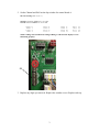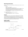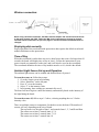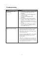
1
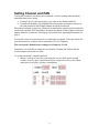
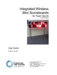
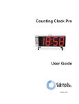
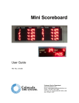
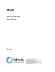
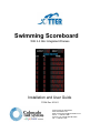
Swimming Scoreboard With 2.4 GHz Integrated Wireless Installation and User Guide F1004 Rev. 201411 Customer Service Department www.coloradotime.com Email: [email protected] Phone: +1 970-667-1000 Toll Free U.S. /Canada 800-287-0653 Fax: +1 970-667-1032 Manufacturer: Everlast Climbing Industries, Inc. DBA Colorado Time Systems 1551 East 11th Street Loveland, CO 80537 USA Sales: 1-800-279-0111 or +1 970-667-1000 Service: 1-800-287-0653 or +1 970-667-1000 Service Fax: 970-667-1032 Web: www.coloradotime.com Email: [email protected] Product Identification Product: Multiline Scoreboards Model Numbers: MS-0149 through MS-0151 MS-0155 Power Specification 320W power supply: 100-240V, 50/60Hz, max 4A Information in this manual is subject to change without notice. Pictures and illustrations may not accurately depict your version. Please check our website for the most current information; our user manuals are available online in the customer service section of our website. Part Number F1004, Rev. 201411 ©2014 Colorado Time Systems. All rights reserve Contents .............................................................................................................................. 1 Swimming Scoreboard ....................................................................................... 1 Product Overview ....................................................................................................... 1 Scoreboard Installation Preparation ................................................................................ 1 Physical mounting ........................................................................................................... 1 Setting Channel and PAN ............................................................................................... 2 Operating Instructions ..................................................................................................... 4 Dolphin ....................................................................................................................... 4 Sports console ............................................................................................................. 4 Troubleshooting .............................................................................................................. 6 No data appears on the scoreboard...................................................................... 6 Expected data does not appear on the scoreboard............................................ 6 Standards followed.......................................................................................................... 7 Product Overview The Otter multiline scoreboards for Swimming can be used indoors or outdoors. They feature a lightweight aluminum enclosure and plastic weather covers over the digits. The scoreboard is operated wirelessly when controlled by a Dolphin timing system, or a CTS sports console. When used wirelessly, the scoreboard is controlled by a certified radio patch antenna that is mounted internally which keeps it protected from damage. It can be operated wired when controlled by a CTS sports console. The scoreboards also contain ambient light sensors, which can be enabled by a System 6 to detect external light and shadows and then adjust the display so that it visually maintains the optimal digit intensity in the display. Scoreboard Installation Preparation When a board is used outdoors, the power cord must be used in conjunction with an outdoor-rated receptacle. **Typically, it is more convenient to complete the Channel and PAN settings (if necessary) on the ground prior to mounting the board. Instructions are on following pages. It is the owner’s responsibility to follow all applicable electrical and structural codes. It is the owner’s responsibility to follow all applicable building codes. Required mounting/installation drawings showing board dimensions, attachment points and weight are available from www.coloradotime.com Physical mounting Determine the location for the scoreboard. It is the owner’s responsibility to choose a location which can support the weight of the scoreboard, which is listed in the installation drawing. The scoreboard is mounted to a wall, corner or pole using kits that can be purchased separately. Follow the instructions that are included with that mounting kit. Scoreboard support structures are the responsibility of the facility, and must be designed by a qualified structural engineer to meet all national and local codes. Refer to scoreboard installation drawing, showing the boards’ dimensions, attachment points and weight. The board must not be connected to live AC power during installation. 1 Setting Channel and PAN If using the scoreboard wirelessly, the scoreboard’s wireless settings must match the transmitter that you are using. If using a WA-2 with a sports timer, you must set the channel and PAN. If using with Dolphin, your Dolphin Base (and watches and starter) must be on the same channel as the Dolphin Adapter inside the scoreboard. When the scoreboard is turned on, it displays an initialization routine which includes the scoreboard’s channel, PAN and address, and then the channel of the Dolphin scoreboard adapter inside the scoreboard. This display is described in the Operating Instructions on page 4. It is usually easiest to set the data source to match the scoreboard. To do this, follow the user instructions for your data source transmitter (WA-2 or Dolphin). The scoreboard’s default factory settings are Channel 6 / PAN 0 Sometimes it is preferable to change the scoreboard’s Channel and PAN to match a wireless adapter connected to a timer. To set the scoreboard’s Channel and PAN: 1. Remove end cap of one side by removing the screws. Slide out the second weather cover to expose control board A (see image below). Place all of these materials in a safe place for later re-installation. 2 2. Set the Channel and PAN on the dip switches for control board A. DIP switch settings (Off = 0, On = 1) Channels: Switches 1-4 of S2. 0 to 11 are valid PAN ID: Switches 5-8 of S2. 0 to 15 are valid 0000 1000 0100 1100 0 1 2 3 0010 1010 0110 1110 4 5 6 7 0001 8 1001 9 0 1 0 1 10 1 1 0 1 11 0011 1011 0111 1111 12 13 14 15 NOTE: Settings of S1 should not be changed. Doing so will cause the display to cease functioning properly. S2 3. Replace any digits you removed. Replace the weather covers. Replace end cap. 3 Operating Instructions Once the scoreboard is powered up it displays an initialization routine on lanes 1, 4, and 7 (if present): - LEDs on - Digits count up 0 through 9 - Displays version number of scoreboard firmware - Rotates through address, channel and PAN at least 3 times. For example, a board set to address 1, channel 4 and PAN 0 would show A01, C06, and P00. - Shows Dolphin information for 30 seconds: channel number under Lane and Place, two other numbers, and Dolphin scoreboard adapter firmware revision in the 4 rightmost digits. The scoreboard is then ready for signals from its data source: - Dolphin timing system, or - CTS sports console (System 6, System 5, or System 4000). Dolphin The Dolphin system is native wireless and needs no additional hardware. The Dolphin system and Dolphin scoreboard adapter inside the scoreboard must be set to the same channel. Note the Dolphin channel displayed under Lane and Place during initialization, and follow instructions in the Dolphin quick reference guide to set the Dolphin base to the same channel. You can then follow the Dolphin user instructions to wirelessly change the channel of the Dolphin adapter inside the scoreboard if desired. Sports console Cabled connection: Sports consoles can be connected by cables to the scoreboard. Use a data cable (R-xxDC) to connect your sports timer to the round quarter-inch RS-232 jack on the bottom of the scoreboard. 4 Wireless connection: When using a wireless connection, the WA-2 wireless adapter and scoreboard must be set to the same channel and PAN. Follow the WA-2 user instructions to change its channel and PAN. Follow instructions on previous pages if scoreboard Channel and PAN must be changed. Displaying data correctly Proper operation of the scoreboard with sports timer data requires the default scoreboard module definitions on the sports timer. Time of Day When the scoreboard is on but does not receive data from a data source for longer than 30 seconds, the board will display time of day in Lane 1. Follow the instructions in your sports console user manual to set the time, and it will also be saved to the scoreboard. The scoreboard definition for time of day module must be set 16, which is the default. Ambient Light Sensor Set-up and Operation The ambient light sensors can be enabled and disabled from a System 6. To turn the sensor on, follow these steps: 1. Go to the Setups screen in Swimming 2. Select “Hardware” on the left pane 3. Press “0” to set the intensity 4. Select “2” as the intensity value 5. In Swimming, these settings are automatically saved. The board will now begin to control the intensity automatically based on the intensity of the light hitting the board. To turn the sensor off, follow steps 1-3 above, selecting anything above a 2 for the intensity value. There are multiple sensors to compensate for shadows across the board. The number of sensors will vary depending on the size of board. The top sensor is to the right of lane 1, and controls lanes 1, 2, 3 and Event/Heat. The sensor next to lane 3 controls lanes 4, 5, 6 The sensor next to lane 5 controls lanes 7, 8, 9 The sensor next to lane 7 controls lane 10 5 Troubleshooting Issue No data appears on the scoreboard Expected data does not appear on the scoreboard Solutions 1. Check that the scoreboard is turned on. The power switch is on the right end of the scoreboard. 2. Check that the scoreboard is plugged in to a working AC outlet. 3. Check that timer is plugged in and functioning. 4. Check that any cables are firmly attached 5. If using a wireless adapter, consult the user instructions for that adapter, and make sure that all settings (channel, etc.) are configured correctly 6. Ensure that the scoreboard is not “blanked” from the sports timer. Consult your timer’s user’s manual for details. Garbled data is displayed: If you are sending data from a sports timer older than the System 6, make sure the timer is set to high speed data rather than low speed data. (The System 6 only sends high speed data). Incorrect or missing data: Make sure the timer’s scoreboard module definitions are set to the default settings. Make sure you only have one active data source at a time. A sport console connected with a wire will override any wireless data sources. Dolphin will override data sent via WA-2. 6 Standards followed UL 48 Issue:2011/09/02 Ed:15 Rev:2012/05/04 UL Standard for Safety Electric Signs CAN/CSA C22.2#207 Issue:1989/01/01 Portable and Stationary Electric Signs and Displays General Instruction No 1: 1989/10/01 - (R2008) FCC 47CFR 15B clB Issued:2011/04/21 Title 47 CFR Part 15 Subpart B Unintentional Radiators Class A Verification ICES 003 Issue:2004/01/01 Issue No.4 Interference-Causing Equipment Standard, Digital Apparatus 7 Customer Service Department www.coloradotime.com Email: [email protected] Phone: 970-667-1000 Toll Free U.S. and Canada 800-287-0653 Fax: 970-667-1032