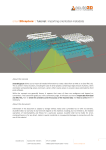
1
UDgateway Entry-Level Appliance Hardware Guide V 5.3 Ref.: RD-HGLGW050300-EN-02 The law of 11 March 1957, paragraphs 2 and 3 of article 41, only authorizes, firstly, "copies and reproductions strictly reserved for use by copyists and not for general use and, secondly, analyses and short quotations for the purpose of example and illustration. Therefore, "any representation or reproduction, entire or partial, made without the consent of the author or his representatives is illegal" (paragraph 1 of article 40). Any such representation or reproduction, made in any manner whatever, would therefore constitute an infringement of the law as sanctioned by articles 425 an in accordance with the penal code. Information contained in this document is subject to change without prior notice and does not constitute any form of obligation on the part of OneAccess. OneAccess and the distributors can in no case be held responsible for direct or indirect damage of any kind incurred as a result of any error in the software or guide. Copyright © OneAccess 2012 All rights reserved Ref.: RD-HGLGW050300-EN-02 - UDcast Technology Contents 1. Read Me First . . . . . . . . . . . . . . . . . . . . . . . . . . 1 1.1. Who should use this manual . . . . . . . . . . . . . . . . . . . . . 1 1.2. How to use this manual . . . . . . . . . . . . . . . . . . . . . . . . . 1 1.2.1. Conventions . . . . . . . . . . . . . . . . . . . . . . . . . . . . . . . . . . . . . . . 1 1.3. General safety instructions . . . . . . . . . . . . . . . . . . . . . . . 2 2. UDgateway Overview . . . . . . . . . . . . . . . . . . . 3 2.1. Hardware model : E5 . . . . . . . . . . . . . . . . . . . . . . . . . . . 3 2.1.1. Front Panel . . . . . . . . . . . . . . . . . . . . . . . . . . . . . . . . . . . . . . . . 3 2.1.2. Rear Panel . . . . . . . . . . . . . . . . . . . . . . . . . . . . . . . . . . . . . . . 4 2.2. Hardware model : E4 . . . . . . . . . . . . . . . . . . . . . . . . . . . 5 2.2.1. Front Panel . . . . . . . . . . . . . . . . . . . . . . . . . . . . . . . . . . . . . . . . 5 2.2.2. Rear Panel . . . . . . . . . . . . . . . . . . . . . . . . . . . . . . . . . . . . . . . 6 2.3. Hardware model : E3 . . . . . . . . . . . . . . . . . . . . . . . . . . . 7 2.3.1. Front Panel . . . . . . . . . . . . . . . . . . . . . . . . . . . . . . . . . . . . . . . . 7 3. UDgateway Installation . . . . . . . . . . . . . . . . . . 9 3.1. Safety first . . . . . . . . . . . . . . . . . . . . . . . . . . . . . . . . . . . . 9 3.1.1. Safety instructions . . . . . . . . . . . . . . . . . . . . . . . . . . . . . . . . . . 9 3.2. General requirements . . . . . . . . . . . . . . . . . . . . . . . . . . . 9 3.2.1. Environment . . . . . . . . . . . . . . . . . . . . . . . . . . . . . . . . . . . . . . . 9 3.2.2. Airflow and cooling . . . . . . . . . . . . . . . . . . . . . . . . . . . . . . . . . 10 3.2.3. Electrical power requirements . . . . . . . . . . . . . . . . . . . . . . . . 10 3.2.4. Attention . . . . . . . . . . . . . . . . . . . . . . . . . . . . . . . . . . . . . . . . . 10 3.3. Before installing a UDgateway® . . . . . . . . . . . . . . . . . . 11 3.3.1. Pre-requisites . . . . . . . . . . . . . . . . . . . . . . . . . . . . . . . . . . . . 11 3.3.1.1. Network access . . . . . . . . . . . . . . . . . . . . . . . . . . . . . . . . . . . . . . . . . . 11 3.3.1.2. Console access . . . . . . . . . . . . . . . . . . . . . . . . . . . . . . . . . . . . . . . . . . 11 3.3.1.3. Tools . . . . . . . . . . . . . . . . . . . . . . . . . . . . . . . . . . . . . . . . . . . . . . . . . . . 11 3.3.2. Prepare network architecture . . . . . . . . . . . . . . . . . . . . . . . . . 12 3.4. Hardware installation details . . . . . . . . . . . . . . . . . . . . . 13 3.4.1. Unpacking notes . . . . . . . . . . . . . . . . . . . . . . . . . . . . . . . . . . . 13 3.4.2. Connections . . . . . . . . . . . . . . . . . . . . . . . . . . . . . . . . . . . . . . 14 3.4.2.1. Ethernet connections . . . . . . . . . . . . . . . . . . . . . . . . . . . . . . . . . . . . . . 14 3.4.2.2. Serial console connection . . . . . . . . . . . . . . . . . . . . . . . . . . . . . . . . . . 15 UDgateway - Hardware Guide Ref: RD-HGLGW050300-EN-02 III Contents 4. Technical Data . . . . . . . . . . . . . . . . . . . . . . . . 17 4.1. UDgateway E5 hardware specifications . . . . . . . . . . . . 17 4.1.1. 4.1.2. 4.1.3. 4.1.4. Size and weight specifications . . . . . . . . . . . . . . . . . . . . . . . . Environmental specifications . . . . . . . . . . . . . . . . . . . . . . . . . Electrical specifications . . . . . . . . . . . . . . . . . . . . . . . . . . . . . Port specifications . . . . . . . . . . . . . . . . . . . . . . . . . . . . . . . . . 4.1.4.1. 4.1.4.2. 4.1.4.3. 4.1.4.4. Ethernet ports . . . . . . . . . . . . . . . . . . . . . . . . . . . . . . . . . . . . . . . . . . . Console ports . . . . . . . . . . . . . . . . . . . . . . . . . . . . . . . . . . . . . . . . . . . Fans . . . . . . . . . . . . . . . . . . . . . . . . . . . . . . . . . . . . . . . . . . . . . . . . . . . Storage . . . . . . . . . . . . . . . . . . . . . . . . . . . . . . . . . . . . . . . . . . . . . . . . 17 17 17 17 17 17 18 18 4.1. UDgateway E4 hardware specifications . . . . . . . . . . . . 19 4.1.1. 4.1.2. 4.1.3. 4.1.4. 4.2. 4.3. 4.4. 4.5. Size and weight specifications . . . . . . . . . . . . . . . . . . . . . . . . Environmental specifications . . . . . . . . . . . . . . . . . . . . . . . . . Electrical specifications . . . . . . . . . . . . . . . . . . . . . . . . . . . . . Port specifications . . . . . . . . . . . . . . . . . . . . . . . . . . . . . . . . . 4.1.4.1. 4.1.4.2. 4.1.4.3. 4.1.4.4. Ethernet ports . . . . . . . . . . . . . . . . . . . . . . . . . . . . . . . . . . . . . . . . . . . Console ports . . . . . . . . . . . . . . . . . . . . . . . . . . . . . . . . . . . . . . . . . . . Fans . . . . . . . . . . . . . . . . . . . . . . . . . . . . . . . . . . . . . . . . . . . . . . . . . . . Storage . . . . . . . . . . . . . . . . . . . . . . . . . . . . . . . . . . . . . . . . . . . . . . . . Declaration Declaration Declaration Declaration of of of of conformity conformity conformity conformity CE . . . . . . . . . . . . . . . . . . . . CE . . . . . . . . . . . . . . . . . . . . RoHS (E5 model) . . . . . . . . . RoHS (E4 model) . . . . . . . . . 19 19 19 19 19 19 20 20 21 22 23 24 5. Compatibility matrix . . . . . . . . . . . . . . . . . . . 25 5.1. Hardware/ software compatibility matrix . . . . . . . . . . . . 25 5.2. Check the hardware model . . . . . . . . . . . . . . . . . . . . . . 26 IV Ref: RD-HGLGW050300-EN-02 UDgateway - Hardware Guide Contents LIST OF FIGURES Figure Figure Figure Figure Figure Figure Figure Figure Figure Figure Figure 1 - UDgateway - E5 hardware - Front Panel . . . . . . . . . . . . . . . . . . . . . . . . 3 2 - UDgateway - E5 hardware - Rear Panel . . . . . . . . . . . . . . . . . . . . . . . . 4 3 - UDgateway - E4 hardware - Front Panel . . . . . . . . . . . . . . . . . . . . . . . . 5 4 - UDgateway - E4 hardware - Rear Panel . . . . . . . . . . . . . . . . . . . . . . . . 6 5 - UDgateway - E3 hardware - Front Panel . . . . . . . . . . . . . . . . . . . . . . . . 7 6 - Content of the package . . . . . . . . . . . . . . . . . . . . . . . . . . . . . . . . . . . . . 13 7 - Ethernet connections - Typical network architecture . . . . . . . . . . . . . . 14 8 - Scenario with 1 switch . . . . . . . . . . . . . . . . . . . . . . . . . . . . . . . . . . . . . . 14 9 - Scenario with 2 switches . . . . . . . . . . . . . . . . . . . . . . . . . . . . . . . . . . . . 14 10 - Scenario with 1 physical switch on VLAN technology . . . . . . . . . . . . 15 11 - UDadmin welcome page . . . . . . . . . . . . . . . . . . . . . . . . . . . . . . . . . . . 26 UDgateway - Hardware Guide Ref: RD-HGLGW050300-EN-02 V Contents This page is intentionally blank VI Ref: RD-HGLGW050300-EN-02 UDgateway - Hardware Guide 1 1. Read Me First 1.1. Who should use this manual This guide is intended for installation engineers, product support engineers and service personnel. It is not intended for the end-user of the system. 1.2. How to use this manual This user manual is for UDgateway®. Use the instructions in this manual to make physical connections for the installation of the system and to configure the system parameters. This guide is arranged as follows: - Chapter 1 - describes the conventions and the general safety instructions. - Chapter 2 - for an overview of the UDgateway® - Chapter 3 - describes the installation of the UDgateway - Chapter 4 - Technical data - Chapter 5 - Hardware / Software Matrix This manual assumes that you understand the basic concepts of telecommunications as applied to the product described, and that you are familiar with the relevant operational network protocols involved. 1.2.1. Conventions This user manual contains important safety instructions in form of WARNINGS and CAUTIONS. These instructions are enclosed in a tinted area. WARNINGS are concerned with your safety; that is, preventing death or injury. CAUTIONS are concerned with preventing damage to equipment. You must read, understand, and obey all safety instructions in this manual before proceeding with any installation or maintenance procedures, as they concern your safety, the safety of others, and the reliability of the equipment with which you are working. This chapter contains important general safety instructions. Specific important safety instructions are provided throughout this manual in the instructions where necessary. UDgateway - Hardware Guide Ref: RD-HGLGW050300-EN-02 1 Read Me 1.3. General safety instructions Comply with all national and local safety requirements when installing this equipment. Additionally, note the following general safety instructions: WARNING Do not install the equipment if it is damaged. Notify the supplier immediately to arrange replacement equipment/parts. WARNING In case of fire 1. Switch off power to the equipment immediately 2. Call Fire Service 3. Use a Carbon Dioxide (CO2) or Dry Powder fire extinguisher DO NOT USE WATER WARNING When moving equipment: Do not move equipment when it is electrically connected 2 Ref: RD-HGLGW050300-EN-02 UDgateway - Hardware Guide 2 1 2. UDgateway Overview 2.1. Hardware model : E5 The UDgateway® Entry-Level appliance is intended for installation on desktops or shelves. IMPORTANT The UDgateway® Entry-Level appliance is a desktop unit and so, is not intended to be stacked between other units. UDgateway should not be covered and pads should not be removed in order to allow proper air flow both on top and bottom. 2.1.1. Front Panel A number of elements are situated on the front panel of the UDgateway that enable you to check that the UDgateway is correctly connected.. 2 4 6 1 3 5 7 Figure 1 - UDgateway - E5 hardware - Front Panel 1 Ethernet Activity LED (LAN-fxp0) Green: Network link exists Flashing green: Network activity 2 Ethernet transfer rate status LED (LAN-fxp0) Green: Turns on 1000 Mbits/s link Orange: Turns on100 Mbits/s link No color: Turns on 10 Mbits/s link 3 Ethernet Activity LED (WAN-xl0) Green: Network link exists Flashing green: Network activity 4 Ethernet transfer rate status LED (WAN-xl0) Green: Turns on 1000 Mbits/s link Orange: Turns on100 Mbits/s link No color: Turns on 10 Mbits/s link 5 Hard disk activity LED - Flashing yellow - activity 6 Ethernet bypass LED - Green = bypass mode 7 Power LED - Green = system is ON UDgateway - Hardware Guide Ref: RD-HGLGW050300-EN-02 3 UDgateway Overview 2.1.2. Rear Panel All connections are made from the rear panel. The rear panel provides the following connectors: 1 2 3 4 5 6 Figure 2 - UDgateway - E5 hardware - Rear Panel 1 Power connector +12V DC 2 Serial port connector (RJ45) = Console port 3 USB 2.0 connectors 4 Reset button 5 WAN (fxp0) - RJ-45 Ethernet connector - Optimized interface Speed indicated LED on the left - Green if 1 Gbps - Yellow if 100 Mpbs Link/Activity LED on the right 6 LAN (xl0) - RJ-45 Ethernet connector - Interception interface Speed indicated LED on the left - Green if 1 Gbps - Yellow if 100 Mpbs Link/Activity LED on the right IMPORTANT: Reset button should not be used. UDgateway must be rebooted from UDadmin web interface. Note: Serial connector can be used to directly access UDgateway console when there is no network connectivity. 4 Ref: RD-HGLGW050300-EN-02 UDgateway - Hardware Guide UDgateway Overview 2.2. Hardware model : E4 The UDgateway® Entry-Level appliance is intended for installation on desktops or shelves. IMPORTANT The UDgateway® Entry-Level appliance is a desktop unit and so, is not intended to be stacked between other units. UDgateway should not be covered and pads should not be removed in order to allow proper air flow both on top and bottom. 2.2.1. Front Panel A number of elements are situated on the front panel of the UDgateway that enable you to check that the UDgateway is correctly connected.. 2 4 6 1 3 5 7 Figure 3 - UDgateway - E4 hardware - Front Panel 1 Ethernet Activity LED (fxp0-LAN) Green: Network link exists Flashing green: Network activity 2 Ethernet transfer rate status LED (fxp0-LAN) Orange: Turns on100 Mbits/s link No color: Turns on 10 Mbits/s link 3 Ethernet Activity LED (xl0-WAN) Green: Network link exists Flashing green: Network activity 4 Ethernet transfer rate status LED (xl0-WAN) Orange: Turns on100 Mbits/s link No color: Turns on 10 Mbits/s link 5 Hard disk activity LED - Flashing green - activity 6 Ethernet bypass LED - Red = bypass mode 7 Power LED - Green = system is ON UDgateway - Hardware Guide Ref: RD-HGLGW050300-EN-02 5 UDgateway Overview 2.2.2. Rear Panel All connections are made from the rear panel. The rear panel provides the following connectors: 2 1 3 4 5 6 Figure 4 - UDgateway - E4 hardware - Rear Panel 1 Power connector +12V DC 2 Serial connector (RS-232) = Console port 3 Reset button 4 xl0 (WAN) - RJ-45 Ethernet connector - Optimized interface 5 fxp0 (LAN) - RJ-45 Ethernet connector - Interception interface 6 USB 2.0 connector IMPORTANT: Reset button should not be used. UDgateway must be rebooted from UDadmin web interface. Note: Serial connector can be used to directly access UDgateway console when there is no network connectivity. 6 Ref: RD-HGLGW050300-EN-02 UDgateway - Hardware Guide UDgateway Overview 2.3. Hardware model : E3 The UDgateway® hardware mode E3 was known as UDgateway-Flex model in previous versions. It corresponds to the following part number: - ACH-AGW-MUE-4.x:* 2.3.1. Front Panel A number of elements are situated on the front panel of the UDgateway® that enable you to check that the UDgateway® is correctly connected. Figure 5 - UDgateway - E3 hardware - Front Panel UDgateway - Hardware Guide Ref: RD-HGLGW050300-EN-02 7 UDgateway Overview This page is intentionally blank 8 Ref: RD-HGLGW050300-EN-02 UDgateway - Hardware Guide 3 1 3. UDgateway Installation 3.1. Safety first Read these safety instructions before starting any installation work. Refer also to the general safety instructions at the beginning of this manual. 3.1.1. Safety instructions WARNING Before applying power to any equipment you are using or installing, look for possible hazards such as moist floors, ungrounded power extension cables or missing safety grounds, and locate the emergency power switch for the room in which you are working so you can isolate power quickly if necessary. WARNING If an electrical accident occurs, turns off the emergency power switch for the room in which you are working, cautiously unplug the UDgateway®'s power, and get medical assistance for any injured person. WARNING Do not work alone in potentially hazardous conditions - take all precautions to remove the hazard first. WARNING Keep tools away from walk areas where you and others could fall over them. CAUTION Keep the UDgateway® area clean and dust-free during and after installation. 3.2. General requirements You should make sure that the following general requirements are met before proceeding with the installation. 3.2.1. Environment The UDgateway® must be installed in: - a clean, dust free environment - an area without direct sunlight, close proximity to heat sources, or high levels of electromagnetic interference (EMI). UDgateway - Hardware Guide Ref: RD-HGLGW050300-EN-02 9 UDgateway Installation 3.2.2. Airflow and cooling Provision must be made for: - at least 10 cm free space around the UDgateway® for proper air flow - ensuring that the UDgateway® temperature and humidity environment can be maintained - see 'Technical Data' chapter. A sufficient air supply for the system must be provided. Be sure that no obstacles are blocking the airflow to the air inlet 3.2.3. Electrical power requirements - Ensure that the UDgateway® installation can be electrically bonded to a suitable 'Safety Earth' - Ensure that the power circuit can deliver the UDgateway® needs - see 'Technical Data' chapter. WARNING - Electrical Utility Connections - All electrical installation work must be carried out by a qualified electrician. - Before connection to a network the UDgateway® and associated equipment must be wired to a suitable protective 'Safety Earth'. - Make sure that all external units cabling are routed so as not to present a hazard to personnel. 3.2.4. Attention To prevent damage, do not remove the cover and avoid touching the internal components as this could affect the guarantee of the product. 10 Ref: RD-HGLGW050300-EN-02 UDgateway - Hardware Guide UDgateway Installation 3.3. Before installing a UDgateway® 3.3.1. Pre-requisites Before installing the UDgateway®, check that following requirements have been met. 3.3.1.1. Network access The standard scenario to configure UDgateway is using a web browser through TCP/ IP connectivity. Any computer with an OS supporting a standard TCP/IP stack and a recent web browser will do. 3.3.1.2. Console access In some scenarios, where you cannot connect to the UDgateway through Ethernet (TCP/IP) and a web browser, you may need to access the UDgateway through a console port to restore connectivity. UDgateway console port can be accessed either through: - screen or keyboard (connected to the UDgateway) - or a serial connection (which requires a serial crossover cable connected between UDgateway serial port and computer as well as a serial terminal software installed on computer). Note: The UDgateway serial port default configuration parameters are: - Baud rate: 115200 - Data Bits: 8 - Parity: None - Stop bits: 1 - Flow control: None 3.3.1.3. Tools No specialised tools are recommended other than tools found in a standard telecom installation engineers toolkit. UDgateway - Hardware Guide Ref: RD-HGLGW050300-EN-02 11 UDgateway Installation 3.3.2. Prepare network architecture Before continuing, you should decide on the following: - where you will be locating your equipment, - how you will be ensuring network connectivity, - and what will be your IP addressing. This is a pre-requisite of installation and configuration. With this information in hand, you will be able to proceed by following the steps described below. 12 Ref: RD-HGLGW050300-EN-02 UDgateway - Hardware Guide UDgateway Installation 3.4. Hardware installation details The procedure to install the UDgateway® successfully is as follows: 1. Unpack the UDgateway® and check the contents of the package 2. Interconnect the UDgateway® for configuration For more detailed information on the hardware installation procedure, please refer to the following paragraphs. 3.4.1. Unpacking notes Unpack and check the contents of the shipping packaging. Verify that the following are included with your shipment: - 1 UDgateway® in its protection wrapping - - - - - 1 power cable (in conformity with Continental Europe standards) 1 AC adapter 1 RJ45 Ethernet crossover cable with RJ45 sockets (length: 2 meters). 1 CD documentation UDgateway 1 flyer: Read Me Figure 6 - Content of the package Examine shipping packaging and system parts for physical damage and shortages report damage/shortages immediately to the supplier. Retain damaged shipping material and damaged parts for damage reports. Preserve the box as well as the protective polystyrene: they are adapted to the transport of your UDgateway®. CAUTION Static electricity may damage the components of your UDgateway®. UDgateway - Hardware Guide Ref: RD-HGLGW050300-EN-02 13 UDgateway Installation 3.4.2. Connections All connectors are on the rear side of the UDgateway®. Connect all cables according to the cabling plan below. 3.4.2.1. Ethernet connections - xl0 (WAN) - This interface must be connected to the Constraint Network. - fxp0 (LAN) - This interface must be used for initial configuration (step-by-step configuration) Traffic going through fxp0 interface is intercepted in order to be optimized when going through xl0 interface. Ethernet Constraint Network xl0 (WAN) UDgateway Ethernet fxp0 (LAN) Figure 7 - Ethernet connections - Typical network architecture Remark: A constraint Network is a network with long delays and bandwidth limitations which requires optimization. It is highly recommended that fxp0 and xl0 interfaces are connected to different Ethernet switches. If the same Ethernet switch is used, fxp0 and xl0 Ethernet segment should be isolated using VLAN technology. Ethernet crossover xl0 (WAN) UDgateway fxp0 (LAN) Ethernet switch Figure 8 - Scenario with 1 switch xl0 (WAN) UDgateway Ethernet switch fxp0 (LAN) Ethernet switch Figure 9 - Scenario with 2 switches 14 Ref: RD-HGLGW050300-EN-02 UDgateway - Hardware Guide UDgateway Installation VLAN xl0 (WAN) UDgateway xl0 (WAN) fxp0 (LAN) VLAN fxp0 (LAN) Ethernet switch VLAN capable Figure 10 - Scenario with 1 physical switch on VLAN technology 3.4.2.2. Serial console connection There is a possibility to access the UDgateway console port through a serial port which can be used when network connectivity has been lost or when your Data Center has been equipped for monitoring through serial connections (either directly or via a modem). Note: The UDgateway serial port default configuration parameters are: - Baud rate: 115200 - Data Bits: 8 - Parity: None - Stop bits: 1 - Flow control: None UDgateway - Hardware Guide Ref: RD-HGLGW050300-EN-02 15 UDgateway Installation This page is intentionally blank 16 Ref: RD-HGLGW050300-EN-02 UDgateway - Hardware Guide 4 1 4. Technical Data 4.1. UDgateway E5 hardware specifications 4.1.1. Size and weight specifications Height: Width: Depth: Weight: 44 mm (1.7 inch) 232 mm (9.1 inch) 153,3 mm (6 inch) 1.5 kg (3.3 lb) 4.1.2. Environmental specifications Temperature range - Operating: +0°C to +40°C (32°F -104°F) - Storage: -20°C to +75°C (-4°F - 167°F) Humidity range - Operating: 5% to 85% relative humidity, non-operating, non-condensing Estimated MTBF - 94017 H at 40°C (104 °F) 4.1.3. Electrical specifications Power requirements 60 W external power supply adapter - Input: 100-240V AC, Frequency 50-60 Hz, 1,7 A - Output: 12V, 5A Compliance approvals - CE and RoHS conformity 4.1.4. Port specifications 4.1.4.1. Ethernet ports - 2 x Gigabit Ethernet interfaces (10/100/1000 Mbps) . 1 for interception (LAN0) . 1 for optimization (WAN0) - Ethernet Bypass support in Bridge mode . Yes between LAN0 and WAN0 4.1.4.2. Console ports - 1 x serial port connection ( RJ45 connector) UDgateway - Hardware Guide Ref: RD-HGLGW050300-EN-02 17 Technical Data 4.1.4.3. Fans - Yes (can run fanless in ventilated IT room) 4.1.4.4. Storage - OS storage on Internal Flash Disk - Data storage on Memory Remark: Specifications are subject to change without notice 18 Ref: RD-HGLGW050300-EN-02 UDgateway - Hardware Guide Technical Data 4.1. UDgateway E4 hardware specifications 4.1.1. Size and weight specifications Height: Width: Depth: Weight: 44 mm (1.7 inch) 232 mm (9.1 inch) 153,3 mm (6 inch) 1.5 kg (3.3 lb) 4.1.2. Environmental specifications Temperature range - Operating: +0°C to +40°C (32°F -104°F) - Storage: -20°C to +75°C (-4°F - 167°F) Humidity range - Operating: 5% to 95% relative humidity, non-operating, non-condensing Estimated MTBF - 75880 H at 25°C (77 °F) 4.1.3. Electrical specifications Power requirements 60 W external power supply adapter - Input: 100-240V AC, Frequency 50-60 Hz, 1,7 A - Output: 12V, 5A Compliance approvals - CE and RoHS conformity 4.1.4. Port specifications 4.1.4.1. Ethernet ports - 2 x Fast Ethernet interfaces (10/100 Mbps) . 1 for interception (fxp0) . 1 for optimization (xl0) - Ethernet Bypass support in Bridge mode . Yes between fxp0 and xl0 4.1.4.2. Console ports - 1 x RS-232 serial port connection UDgateway - Hardware Guide Ref: RD-HGLGW050300-EN-02 19 Technical Data 4.1.4.3. Fans - No 4.1.4.4. Storage - OS storage on Internal Flash Disk - Data storage on Memory Remark: Specifications are subject to change without notice 20 Ref: RD-HGLGW050300-EN-02 UDgateway - Hardware Guide Technical Data 4.2. Declaration of conformity CE UDgateway Entry-Level appliance (E5 model) is based on an Aewin hardware platform known as SCB-6972, distributed by Pyramid Computer GmbH. Declaration of Conformity Certificate 2012 CAE6972** 23-04-2012 OneAccess Networks UDgateway SCB-6972B-E10 The undersigned hereby declares, that the above-referenced product, to which this declaration relates, is in conformity with the provisions of: Council directive 2004/108/EEC on Electromagnetic Compatibility Council Directive 2006/95/ECC on Low Voltage The testings were done in conformity with the following standards: EN 55022:2008-07, EN 55024:1998+A1:2001+A2:2003 DIN EN 61000-3-2:2010-03; DIN EN 61000-3-3:2009-06 DIN EN 60950-1:2011 The authorized representative of the company Pyramid Computer GmbH, Bötzinger Straße 60, D-79111 Freiburg Friedrich Hansen Geschäftsführer UDgateway - Hardware Guide Ref: RD-HGLGW050300-EN-02 21 Technical Data 4.3. Declaration of conformity CE UDgateway Entry-Level appliance (E4 model) is based on an Aewin hardware platform known as SCB-6970, distributed by Pyramid Computer GmbH. Declaration of Conformity Certificate CAE6970005 20‐05‐2010 UDCast Entry‐Level Appliance UDCB‐6970B‐100‐WB, Aewin SCB6970 based The undersigned hereby declares, that the above‐referenced product, to which this declaration relates, is in conformity with the provisions of: Council directive 2004/108/EEC on Electromagnetic Compatibility Council Directive 2006/95/ECC on Low Voltage The testings were done in conformity with the following standards: EN 55022:2006 Kl.B,; EN 61000‐3‐2:2006; EN 61000‐3‐3+A2:2005; EN 60950‐1:2006 The authorized representative of the company Pyramid Computer GmbH, Bötzinger Straße 60, 79111 Freiburg Friedrich Hansen Geschäftsführer 22 Ref: RD-HGLGW050300-EN-02 UDgateway - Hardware Guide Technical Data 4.4. Declaration of conformity RoHS (E5 model) One Access BU Network Bandwidth Optimization 2455, route des Dolines F-06906 Sophia-Antipolis Freiburg, 23.04.2012 Declaration of Conformity RoHS and WEEE » OneAccess Networks UDgateway (SCB-6972B-E10) Dear Sirs, The law regarding the marketing, withdrawal and environmental disposal of electrical and electronic equipment determines the responsibilities of the manufacturers of electrical and electronic devices, according to (ElektroG) from March 16, 2005 (Federal Law Gazette, part 1, number 17 from March 23, 2005). We confirm that the above listed products are produced in accordance with the RoHS: guidelines (2011/65/EU). The RoHS guidelines contain the material restrictions for electrical and electronic equipment. The use of lead, mercury, cadmium, hexavalent chrome, polybrominated biphenyl (PBB), and polybrominated diphenyl ether (PBDE) is forbidden from then onwards. The manufacturers have confirmed the conformity of their products. Because of these informations, Pyramid Computer can affirm that the delivered products are in accordance with the terms of the RoHS guidelines 2011/65/EU. WEEE: Pyramid Computer GmbH has been a registered manufacturer of professional devices for information and telecommunications technology since November 2005. – The WEEE Registration number: DE 59162004. Best Regards Frieder Hansen - Geschäftsführer - UDgateway - Hardware Guide Ref: RD-HGLGW050300-EN-02 23 Technical Data 4.5. Declaration of conformity RoHS (E4 model) UDcast 2455, Route des Dolines 06906 Sophia Antipolis cedes France Freiburg, den 07.08.2009 Declaration of Conformity RoHS and WEEE Dear Sirs, The law regarding the marketing, withdrawal and environmental disposal of electrical and electronic equipment determines the responsibilities of the manufacturers of those devices, according to (ElektroG) from March 16, 2005 (Federal Law Gazette, part 1, number 17 from March 23, 2005). UDCast MidRange Appliance (CPYUD***) We confirm that the above listed products are produced in accordance with the RoHS: guidelines. The RoHS guidelines contain the material restrictions for electrical and electronic equipment that will be put on the market after July 1, 2006. The use of lead, mercury, cadmium, hexavalent chrome, polybrominated biphenyl (PBB), and polybrominated diphenyl ether (PBDE) is forbidden from then onwards. The manufacturers have confirmed the conformity of their products. The conformity may in particular cases indicates, that manufacturers refer to the server exection, which can still be used until 2010 (attachement of the rules 2002/95/EG, Abs. 7). Because of these informations, Pyramid Computer can affirm that the delivered products are in accordance with the terms of the RoHS guidelines. WEEE: Pyramid Computer GmbH has been a registered manufacturer of professional devices for information and telecommunications technology since November 2005. – The WEEE Registration number: DE 59162004. Best Regards Frieder Hansen - Geschäftsführer - 24 Ref: RD-HGLGW050300-EN-02 UDgateway - Hardware Guide 5 1 5. Compatibility matrix 5.1. Hardware/ software compatibility matrix SOFTWARE VERSION HARDWARE MODEL v3.1 v2 v1 v4.1 v4.3 v5.1 E5 v5.3 q E4 E3 q q q q q q q q q q q E2 E1 E0 q SOFTWARE OPTIONS HARDWARE MODEL CIFS ready WANcompress ready q q q q HARDWARE OPTIONS Service Platform ready E5 Ethernet Bypass ready q E4 q q E3 q q E2 q q E1 E0 Starting with UDgateway software version 5.1, hardware model can be checked from UDgateway web GUI interface. For previous UDgateway software versions, from a sticker usually placed on the rear of the UDgateway, you can check what was your UDgateway part number at delivery time. As a guideline, you can use the table below to identify your hardware model. If you have any doubt, you can contact Technical Support with your UDgateway Serial Number in order to check your hardware model and its compatibility with a software version. HARDWARE MODEL E4,E5 UDgateway - Hardware Guide PART NUMBER AH-GATEWAY-RSO E3 ACH-AGW-MUE-4.*:* E2 ACH-AGW-MUE-3.*:* E1 ACH-AGW-MUE-2.*:* E0 ACH-AGWSA-ME-1.:* ACH-AGWVPN-ME-1.*:* ACH-AGWMA-ME-1.*:* Ref: RD-HGLGW050300-EN-02 25 Hardware/Software compatibility matrix 5.2. Check the hardware model If you benefit from >= v5.x release, you can check hardware model from the UDgateway web GUI interface. For more information about how to enter the UDadmin welcome page, refer to Advanced Configuration Guide. Figure 11 - UDadmin welcome page 26 Ref: RD-HGLGW050300-EN-02 UDgateway - Hardware Guide Reader's Remarks Your comments enable improvements of the document quality; they have a significant role when documents are updated. If you have any comments to make, do not hesitate to tell us about them. Just give us the page and the line references. Your comments will be carefully considered. Please send your remarks to: Service Support OneAccess BP 355 2455 route des Dolines 06906 Sophia-Antipolis Cedex France e-mail : [email protected] For local offices and sales representatives, please visit our website: www.oneaccess-net.com Tel: +33 (0)4 93 00 16 60 Fax: +33 (0)4 93 00 16 61 B.P. 355 - 2455, route des Dolines 06906 Sophia Antipolis cedex France