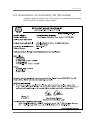
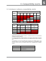
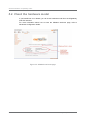
1
UDgateway High-End Appliance Hardware Guide V 5.3 Ref.: RD-HGHGW050300-EN-02 The law of 11 March 1957, paragraphs 2 and 3 of article 41, only authorizes, firstly, "copies and reproductions strictly reserved for use by copyists and not for general use and, secondly, analyses and short quotations for the purpose of example and illustration. Therefore, "any representation or reproduction, entire or partial, made without the consent of the author or his representatives is illegal" (paragraph 1 of article 40). Any such representation or reproduction, made in any manner whatever, would therefore constitute an infringement of the law as sanctioned by articles 425 an in accordance with the penal code. Information contained in this document is subject to change without prior notice and does not constitute any form of obligation on the part of OneAccess. OneAccess and the distributors can in no case be held responsible for direct or indirect damage of any kind incurred as a result of any error in the software or guide. Copyright © OneAccess 2011 All rights reserved Ref.: RD-HGHGW050300-EN-02 - UDcast Technology Contents 1. Read Me First . . . . . . . . . . . . . . . . . . . . . . . . . . 1 1.1. Who should use this manual . . . . . . . . . . . . . . . . . . . . . 1 1.2. How to use this manual . . . . . . . . . . . . . . . . . . . . . . . . . 1 1.2.1. Conventions . . . . . . . . . . . . . . . . . . . . . . . . . . . . . . . . . . . . . . . 1 1.3. General safety instructions . . . . . . . . . . . . . . . . . . . . . . . 2 2. UDgateway Overview . . . . . . . . . . . . . . . . . . . 3 2.1. Hardware model : H5 . . . . . . . . . . . . . . . . . . . . . . . . . . . 3 2.1.1. Front Panel . . . . . . . . . . . . . . . . . . . . . . . . . . . . . . . . . . . . . . . . 3 2.1.2. Rear Panel . . . . . . . . . . . . . . . . . . . . . . . . . . . . . . . . . . . . . . . . 4 2.2. Hardware model : H3 . . . . . . . . . . . . . . . . . . . . . . . . . . . 6 2.2.1. Front Panel . . . . . . . . . . . . . . . . . . . . . . . . . . . . . . . . . . . . . . . . 6 2.2.2. Rear Panel . . . . . . . . . . . . . . . . . . . . . . . . . . . . . . . . . . . . . . . . 7 2.3. Hardware model : H2 . . . . . . . . . . . . . . . . . . . . . . . . . . . 9 2.3.1. Front Panel . . . . . . . . . . . . . . . . . . . . . . . . . . . . . . . . . . . . . . . 9 2.3.2. Rear Panel . . . . . . . . . . . . . . . . . . . . . . . . . . . . . . . . . . . . . . . 10 3. UDgateway Installation . . . . . . . . . . . . . . . . . 11 3.1. Safety first . . . . . . . . . . . . . . . . . . . . . . . . . . . . . . . . . . . 11 3.1.1. Safety instructions . . . . . . . . . . . . . . . . . . . . . . . . . . . . . . . . . 11 3.2. General requirements . . . . . . . . . . . . . . . . . . . . . . . . . . 11 3.2.1. Environment . . . . . . . . . . . . . . . . . . . . . . . . . . . . . . . . . . . . . . 3.2.2. Airflow and cooling . . . . . . . . . . . . . . . . . . . . . . . . . . . . . . . . . 3.2.3. Electrical power requirements . . . . . . . . . . . . . . . . . . . . . . . . 3.2.4. Attention . . . . . . . . . . . . . . . . . . . . . . . . . . . . . . . . . . . . . . . . . 11 12 12 12 3.3. Before installing a UDgateway® . . . . . . . . . . . . . . . . . . 13 3.3.1. Pre-requisites . . . . . . . . . . . . . . . . . . . . . . . . . . . . . . . . . . . . 13 3.3.1.1. Network access . . . . . . . . . . . . . . . . . . . . . . . . . . . . . . . . . . . . . . . . . . 13 3.3.1.2. Console access . . . . . . . . . . . . . . . . . . . . . . . . . . . . . . . . . . . . . . . . . . 13 3.3.1.3. Tools . . . . . . . . . . . . . . . . . . . . . . . . . . . . . . . . . . . . . . . . . . . . . . . . . . . 13 3.3.2. Prepare network architecture . . . . . . . . . . . . . . . . . . . . . . . . . 14 3.4. Hardware installation details . . . . . . . . . . . . . . . . . . . . . 15 3.4.1. Unpacking notes . . . . . . . . . . . . . . . . . . . . . . . . . . . . . . . . . . . 15 3.4.2. Connections . . . . . . . . . . . . . . . . . . . . . . . . . . . . . . . . . . . . . . 16 3.4.2.1. 3.4.2.2. 3.4.2.3. 3.4.2.4. Ethernet connections . . . . . . . . . . . . . . . . . . . . . . . . . . . . . . . . . . . . . . Screen / Keyboard console connection . . . . . . . . . . . . . . . . . . . . . . . . Serial console connection . . . . . . . . . . . . . . . . . . . . . . . . . . . . . . . . . . Rack mounting of the UDgateway . . . . . . . . . . . . . . . . . . . . . . . . . . . . UDgateway - Hardware Guide Ref: RD-HGHGW050300-EN-02 16 18 18 18 III Contents 4. Technical Data . . . . . . . . . . . . . . . . . . . . . . . . 19 4.1. UDgateway H5 hardware specifications . . . . . . . . . . . . 19 4.1.1. 4.1.2. 4.1.3. 4.1.4. Size and weight specifications . . . . . . . . . . . . . . . . . . . . . . . . Environmental specifications . . . . . . . . . . . . . . . . . . . . . . . . . Electrical specifications . . . . . . . . . . . . . . . . . . . . . . . . . . . . . Port specifications . . . . . . . . . . . . . . . . . . . . . . . . . . . . . . . . . 4.1.4.1. 4.1.4.2. 4.1.4.3. 4.1.4.4. 4.1.4.5. Ethernet ports . . . . . . . . . . . . . . . . . . . . . . . . . . . . . . . . . . . . . . . . . . . Console ports . . . . . . . . . . . . . . . . . . . . . . . . . . . . . . . . . . . . . . . . . . . Fans . . . . . . . . . . . . . . . . . . . . . . . . . . . . . . . . . . . . . . . . . . . . . . . . . . . Storage . . . . . . . . . . . . . . . . . . . . . . . . . . . . . . . . . . . . . . . . . . . . . . . . HP iLO Description . . . . . . . . . . . . . . . . . . . . . . . . . . . . . . . . . . . . . . . 19 19 19 19 19 20 20 20 20 4.2. UDgateway H3 hardware specifications . . . . . . . . . . . . 21 4.2.1. 4.2.2. 4.2.3. 4.2.4. Size and weight specifications . . . . . . . . . . . . . . . . . . . . . . . . Environmental specifications . . . . . . . . . . . . . . . . . . . . . . . . . Electrical specifications . . . . . . . . . . . . . . . . . . . . . . . . . . . . . Port specifications . . . . . . . . . . . . . . . . . . . . . . . . . . . . . . . . . 4.2.4.1. 4.2.4.2. 4.2.4.3. 4.2.4.4. 4.2.4.5. Ethernet ports . . . . . . . . . . . . . . . . . . . . . . . . . . . . . . . . . . . . . . . . . . . Console ports . . . . . . . . . . . . . . . . . . . . . . . . . . . . . . . . . . . . . . . . . . . Fans . . . . . . . . . . . . . . . . . . . . . . . . . . . . . . . . . . . . . . . . . . . . . . . . . . . Storage . . . . . . . . . . . . . . . . . . . . . . . . . . . . . . . . . . . . . . . . . . . . . . . . HP iLO Description . . . . . . . . . . . . . . . . . . . . . . . . . . . . . . . . . . . . . . . 21 21 21 21 21 22 22 22 22 4.3. UDgateway H2 hardware specifications . . . . . . . . . . . . 23 4.3.1. 4.3.2. 4.3.3. 4.3.4. 4.4. 4.5. 4.6. 4.7. Size and weight specifications . . . . . . . . . . . . . . . . . . . . . . . . Environmental specifications . . . . . . . . . . . . . . . . . . . . . . . . . Electrical specifications . . . . . . . . . . . . . . . . . . . . . . . . . . . . . Port specifications . . . . . . . . . . . . . . . . . . . . . . . . . . . . . . . . . 4.3.4.1. 4.3.4.2. 4.3.4.3. 4.3.4.4. Ethernet ports . . . . . . . . . . . . . . . . . . . . . . . . . . . . . . . . . . . . . . . . . . . Console ports . . . . . . . . . . . . . . . . . . . . . . . . . . . . . . . . . . . . . . . . . . . Fans . . . . . . . . . . . . . . . . . . . . . . . . . . . . . . . . . . . . . . . . . . . . . . . . . . . Storage . . . . . . . . . . . . . . . . . . . . . . . . . . . . . . . . . . . . . . . . . . . . . . . . Declaration of conformity CE (H5 model) . . . . . . . . . . . Declaration of conformity CE (H3 & H2 models) . . . . . RoHS compliance . . . . . . . . . . . . . . . . . . . . . . . . . . . . . WEEE Compliance . . . . . . . . . . . . . . . . . . . . . . . . . . . . 23 23 23 23 23 24 24 24 25 26 27 32 5. Compatibility matrix . . . . . . . . . . . . . . . . . . . 35 5.1. Hardware/ software compatibility matrix . . . . . . . . . . . . 35 5.2. Check the hardware model . . . . . . . . . . . . . . . . . . . . . . 36 IV Ref: RD-HGHGW050300-EN-02 UDgateway - Hardware Guide Contents LIST OF FIGURES Figure Figure Figure Figure Figure Figure Figure Figure Figure Figure Figure Figure Figure Figure 1 - UDgateway - H5 hardware - Front Panel . . . . . . . . . . . . . . . . . . . . . . . . 3 2 - UDgateway - H5 hardware - Rear Panel . . . . . . . . . . . . . . . . . . . . . . . . 4 3 - UDgateway - H3 hardware - Front Panel . . . . . . . . . . . . . . . . . . . . . . . . 6 4 - UDgateway - H3 hardware - Rear Panel . . . . . . . . . . . . . . . . . . . . . . . . 7 5 - UDgateway - H2 hardware - Front Panel . . . . . . . . . . . . . . . . . . . . . . . . 9 6 - UDgateway - H2 hardware - Rear Panel . . . . . . . . . . . . . . . . . . . . . . . 10 7 - Content of the package . . . . . . . . . . . . . . . . . . . . . . . . . . . . . . . . . . . . . 15 8 - Ethernet connections - Typical network architecture . . . . . . . . . . . . . . 16 9 - Scenario with 1 switch . . . . . . . . . . . . . . . . . . . . . . . . . . . . . . . . . . . . . . 16 10 - Scenario with 2 switches . . . . . . . . . . . . . . . . . . . . . . . . . . . . . . . . . . . 17 11 - Scenario with 1 physical switch on VLAN technology . . . . . . . . . . . . . 17 12 - Multi-WAN scenario with 1 switch . . . . . . . . . . . . . . . . . . . . . . . . . . . . 17 13 - Multi-WAN scenario with 1 physical switch on VLAN technology . . . . 18 14 - UDadmin welcome page . . . . . . . . . . . . . . . . . . . . . . . . . . . . . . . . . . . 36 UDgateway - Hardware Guide Ref: RD-HGHGW050300-EN-02 V Contents This page is intentionally blank VI Ref: RD-HGHGW050300-EN-02 UDgateway - Hardware Guide 1 1. Read Me First 1.1. Who should use this manual This guide is intended for installation engineers, product support engineers and service personnel. It is not intended for the end-user of the system. 1.2. How to use this manual This user manual is for UDgateway®. Use the instructions in this manual to make physical connections for the installation of the system and to configure the system parameters. This guide is arranged as follows: - Chapter 1 - describes the conventions and the general safety instructions. - Chapter 2 - for an overview of the UDgateway® - Chapter 3 - describes the installation of the UDgateway - Chapter 4 - Technical data - Chapter 5 - Hardware / Software Matrix This manual assumes that you understand the basic concepts of telecommunications as applied to the product described, and that you are familiar with the relevant operational network protocols involved. 1.2.1. Conventions This user manual contains important safety instructions in form of WARNINGS and CAUTIONS. These instructions are enclosed in a tinted area. WARNINGS are concerned with your safety; that is, preventing death or injury. CAUTIONS are concerned with preventing damage to equipment. You must read, understand, and obey all safety instructions in this manual before proceeding with any installation or maintenance procedures, as they concern your safety, the safety of others, and the reliability of the equipment with which you are working. This chapter contains important general safety instructions. Specific important safety instructions are provided throughout this manual in the instructions where necessary. UDgateway - Hardware Guide Ref: RD-HGHGW050300-EN-02 1 Read Me 1.3. General safety instructions Comply with all national and local safety requirements when installing this equipment. Additionally, note the following general safety instructions: WARNING Do not install the equipment if it is damaged. Notify the supplier immediately to arrange replacement equipment/parts. WARNING In case of fire 1. Switch off power to the equipment immediately 2. Call Fire Service 3. Use a Carbon Dioxide (CO2) or Dry Powder fire extinguisher DO NOT USE WATER WARNING When moving equipment: Do not move equipment when it is electrically connected 2 Ref: RD-HGHGW050300-EN-02 UDgateway - Hardware Guide 2 1 2. UDgateway Overview 2.1. Hardware model : H5 The UDgateway® High-End appliance is intended for installation in 19-inch telco racks. Characteristics: - Standard 19 inch rack mounting, 1U height - Cover and housing: metal Compared to H3 hardware model, UDgateway H5 hardware model has an additional Ethernet board to connect the UDgateway to a multi-WAAN environment with Link Management option. 2.1.1. Front Panel A number of elements are situated on the front panel of the UDgateway that enable you to check that the UDgateway is correctly connected.. Figure 1 - UDgateway - H5 hardware - Front Panel 1 UID LED/button Blue = Identification is activated Flashing blue = System is being managed remotely Off = Identification is deactivated. 2 Health LED Green = System health is normal Amber = System is degraded. Red = System health is critical. T Off = System health is normal (when in standby mode). 3 Power On/Standby button and system power LED Green = system is on Amber = System is standby, but power is still applied Off = Power cord is not attached, power supply failure has occurred, no power supplies are installed, facility power is not available, or the power button cable is disconnected. UDgateway - Hardware Guide Ref: RD-HGHGW050300-EN-02 3 UDgateway Overview 2.1.2. Rear Panel All connections are made from the rear panel. The rear panel provides the following connectors: 14 15 8 9 11 10 12 13 16 17 7 18 1 6 5 4 2 3 Figure 2 - UDgateway - H5 hardware - Rear Panel 1 Power supply bay 2 2 Power supply bay 1 3 HP iLO management port 4 Serial connector 5 Video connector 6 xl0 (WAN) - RJ-45 Ethernet connector - Optimized interface 7 Led activity xl0 First led: Turns on 100 Mbits/s link (green) Second led: Turns on 1000 Mbits/s link (green) Third led: Turns on any link speed, blinks on activity (green) If bypass: both, first and second leds are green 8 fxp0 (LAN) - RJ-45 Ethernet connector - Interception interface 9 Led activity fxp0 First led: Turns on 100 Mbits/s link (green) Second led: Turns on 1000 Mbits/s link (green) Third led: Turns on any link speed, blinks on activity (green) If bypass: both, first and second leds are green 10xl2 (WAN2) - RJ-45 Ethernet connector - Optimized interface 11Led activity xl2 4 First led: Turns on 100 Mbits/s link (green) Second led: Turns on 1000 Mbits/s link (green) Third led: Turns on any link speed, blinks on activity (green) If bypass: both, first and second leds are green Ref: RD-HGHGW050300-EN-02 UDgateway - Hardware Guide UDgateway Overview 12xl1 (WAN1) - RJ-45 Ethernet connector - Optimized interface 13Led activity xl1 First led: Turns on 100 Mbits/s link (green) Second led: Turns on 1000 Mbits/s link (green) Third led: Turns on any link speed, blinks on activity (green) If bypass: both, first and second leds are green 14USB connectors (2) 15RJ-45 Ethernet connector (UNUSED) 16RJ-45 Ethernet connector (UNUSED) 17RJ-45 Ethernet connector (UNUSED) 18RJ-45 Ethernet connector (UNUSED) UDgateway - Hardware Guide Ref: RD-HGHGW050300-EN-02 5 UDgateway Overview 2.2. Hardware model : H3 The UDgateway® High-End appliance is intended for installation in 19-inch telco racks. Characteristics: - Standard 19 inch rack mounting, 1U height - Cover and housing: metal Compared to H2 hardware model, UDgateway H3 hardware model: - has an additional Ethernet bypass board - is sized to support CPS40 and CSP60 software packages. Note: Thanks to Ethernet bypass board, a power-off of an UDgateway configured in bridge mode will behave as a straight Ethernet cable passing traffic from one side to the other (from fxp0 to xl0 and vice-versa). 2.2.1. Front Panel A number of elements are situated on the front panel of the UDgateway that enable you to check that the UDgateway is correctly connected. 3 1 2 5 4 6 Figure 3 - UDgateway - H3 hardware - Front Panel 1 Power On/Standby button and system power LED Green = system is on Amber = System is shut down, but power is still applied Off = Power cord is not attached, power supply failure has occurred, no power supplies are installed, facility power is not available, or the DC-to-DC converter is not installed. 2 UID button/LED Blue = Identification is activated Flashing blue = System is being remotely managed Off = Identification is deactivated. 3 Internal health LED Green = System health is normal Amber = System is degraded. To identify the component in a degraded state, refer to system board LEDs. Red = System critical. To identify the component in a critical state, refer to system board LEDs Off = System health is normal (when in standby mode). 6 Ref: RD-HGHGW050300-EN-02 UDgateway - Hardware Guide UDgateway Overview 4 External health LED (power supply) Green = Power supply health is normal Amber = Power redundancy failure occurred Off = Power redundancy failure has occurred. When the server is in standby mode, power supply health is normal. 5 UNUSED 6 UNUSED NOTE: Ethernet bypass LEDs for the bypass board are located on the rear panel. 2.2.2. Rear Panel All connections are made from the rear panel. The rear panel provides the following connectors: 12 10 6 3 13 4 11 1 9 5 7 2 8 Figure 4 - UDgateway - H3 hardware - Rear Panel 1 Power supply bay 2 2 Power supply bay 1 3 Serial connector 4 VGA DB 15 Pin connector 5 PS/2 keyboard connector 6 HP iLO management port 7 RJ-45 Ethernet connector (not handled in v5.1 software release) 8 RJ-45 Ethernet connector (not handled in v5.1 software release) 9 xl0 - RJ-45 Ethernet connector - Optimized interface 10Led activity xl0 First led: Turns on 100 Mbits/s link (green) Second led: Turns on 1000 Mbits/s link (green) Third led: Turns on any link speed, blinks on activity (green) If bypass: both, first and second leds are green UDgateway - Hardware Guide Ref: RD-HGHGW050300-EN-02 7 UDgateway Overview 11fxp0 - RJ-45 Ethernet connector - Interception interface 12Led activity fxp0 First led: Turns on 100 Mbits/s link (green) Second led: Turns on 1000 Mbits/s link (green) Third led: Turns on any link speed, blinks on activity (green) If bypass: both, first and second leds are green 13USB connectors Note: VGA / PS/2 connectors or Serial connector can be used to directly access UDgateway console when there is no network connectivity. 8 Ref: RD-HGHGW050300-EN-02 UDgateway - Hardware Guide UDgateway Overview 2.3. Hardware model : H2 The UDgateway® is intended for installation in 19-inch telco racks. Characteristics: - Standard 19 inch rack mounting, 1U height - Cover and housing: metal Note: The UDgateway hardware model H2 has no Ethernet bypass board. Note: H2 model has no HP iLO software license installed, preventing remote console access through HP iLO interface. 2.3.1. Front Panel A number of elements are situated on the front panel of the UDgateway that enable you to check that the UDgateway is correctly connected.. 3 1 2 5 4 6 Figure 5 - UDgateway - H2 hardware - Front Panel 1 Power On/Standby button and system power LED Green = system is on Amber = System is shut down, but power is still applied Off = Power cord is not attached, power supply failure has occurred, no power supplies are installed, facility power is not available, or the DC-to-DC converter is not installed. 2 UID button/LED Blue = Identification is activated Flashing blue = System is being remotely managed Off = Identification is deactivated. 3 Internal health LED Green = System health is normal Amber = System is degraded. To identify the component in a degraded state, refer to system board LEDs. Red = System critical. To identify the component in a critical state, refer to system board LEDs Off = System health is normal (when in standby mode). 4 External health LED (power supply) Green = Power supply health is normal Amber = Power redundancy failure occurred Off = Power redundancy failure has occurred. When the server is in standby mode, power supply health is normal. UDgateway - Hardware Guide Ref: RD-HGHGW050300-EN-02 9 UDgateway Overview 5 NIC 1 link/activity LED Green = Network link exists Flashing green = Network link and activity exist Off = No link to network exists If power is off, view the LEDs on the RJ-45 connector for status by referring to the rear panel LEDs. 6 NIC 2 link/activity LED Green = Network link exists Flashing green = Network link and activity exist Off = No link to network exists If power is off, view the LEDs on the RJ-45 connector for status by referring to the rear panel LEDs. 2.3.2. Rear Panel All connections are made from the rear panel. The rear panel provides the following connectors: 2 1 6 3 4 5 7 8 Figure 6 - UDgateway - H2 hardware - Rear Panel 1 Power supply bay 2 2 Power supply bay 1 3 Serial connector 4 VGA DB 15 Pin connector 5 PS/2 keyboard connector 6 HP iLO management port (iLO software license not installed) 7 fxp0 -RJ45 Ethernet connector - Interception interface 8 xl0 - RJ45 Ethernet connector - Optimized interface 10 Ref: RD-HGHGW050300-EN-02 UDgateway - Hardware Guide 3 1 3. UDgateway Installation 3.1. Safety first Read these safety instructions before starting any installation work. Refer also to the general safety instructions at the beginning of this manual. 3.1.1. Safety instructions WARNING Before applying power to any equipment you are using or installing, look for possible hazards such as moist floors, ungrounded power extension cables or missing safety grounds, and locate the emergency power switch for the room in which you are working so you can isolate power quickly if necessary. WARNING If an electrical accident occurs, turns off the emergency power switch for the room in which you are working, cautiously unplug the UDgateway®'s power, and get medical assistance for any injured person. WARNING Do not work alone in potentially hazardous conditions - take all precautions to remove the hazard first. WARNING Keep tools away from walk areas where you and others could fall over them. CAUTION Keep the UDgateway® area clean and dust-free during and after installation. 3.2. General requirements You should make sure that the following general requirements are met before proceeding with the installation. 3.2.1. Environment The UDgateway® must be installed in: - a clean, dust free environment - an area without direct sunlight, close proximity to heat sources, or high levels of electromagnetic interference (EMI). UDgateway - Hardware Guide Ref: RD-HGHGW050300-EN-02 11 UDgateway Installation 3.2.2. Airflow and cooling Provision must be made for: - at least 10 cm free space around the UDgateway® for proper air flow - ensuring that the UDgateway® temperature and humidity environment can be maintained - See 'Technical Data' chapter. A sufficient air supply for the system must be provided. Be sure that no obstacles are blocking the airflow to the air inlet 3.2.3. Electrical power requirements - Ensure that the UDgateway® installation can be electrically bonded to a suitable 'Safety Earth' - Ensure that the power circuit can deliver the UDgateway® needs - see 'Technical Data' chapter. WARNING - Electrical Utility Connections - All electrical installation work must be carried out by a qualified electrician. - Before connection to a network the UDgateway® and associated equipment must be wired to a suitable protective 'Safety Earth'. - Make sure that all external units cabling are routed so as not to present a hazard to personnel. 3.2.4. Attention To prevent damage, do not remove the cover and avoid touching the internal components as this could affect the guarantee of the product. 12 Ref: RD-HGHGW050300-EN-02 UDgateway - Hardware Guide UDgateway Installation 3.3. Before installing a UDgateway® 3.3.1. Pre-requisites Before installing the UDgateway®, check that following requirements have been met. 3.3.1.1. Network access The standard scenario to configure UDgateway is using a web browser through TCP/ IP connectivity. Any computer with an OS supporting a standard TCP/IP stack and a recent web browser will do. 3.3.1.2. Console access In some scenarios, where you cannot connect to the UDgateway through Ethernet (TCP/IP) and a web browser, you may need to access the UDgateway through a console port. to restore connectivity. UDgateway console port can be accessed either through: - screen or keyboard (connected to the UDgateway) - or a serial connection (which requires a serial crossover cable connected between UDgateway serial port and computer as well as a serial terminal software installed on computer). Note: The UDgateway serial port default configuration parameters are: - Baud rate: 115200 - Data Bits: 8 - Parity: None - Stop bits: 1 - Flow control: None 3.3.1.3. Tools No specialised tools are recommended other than tools found in a standard telecom installation engineers toolkit. UDgateway - Hardware Guide Ref: RD-HGHGW050300-EN-02 13 UDgateway Installation 3.3.2. Prepare network architecture Before continuing, you should decide on the following: - where you will be locating your equipment, - how you will be ensuring network connectivity, - and what will be your IP addressing. This is a pre-requisite of installation and configuration. With this information in hand, you will be able to proceed by following the steps described below. 14 Ref: RD-HGHGW050300-EN-02 UDgateway - Hardware Guide UDgateway Installation 3.4. Hardware installation details The procedure to install the UDgateway® successfully is as follows: 1. Unpack the UDgateway® and check the contents of the package 2. Interconnect the UDgateway® for configuration For more detailed information on the hardware installation procedure, please refer to the following paragraphs. 3.4.1. Unpacking notes Unpack and check the contents of the shipping packaging. Verify that the following are included with your shipment: - 1 UDgateway® in its protection wrapping - - - - - - 2 power cable (in conformity with Continental Europe standards) 1 RJ45 Ethernet crossover cable with RJ45 sockets (length: 2 meters). 1 rack mounting hardware kit and documentation Documentation CD and software products 1 CD documentation UDgateway 1 flyer: Read Me Figure 7 - Content of the package Examine shipping packaging and system parts for physical damage and shortages report damage/shortages immediately to the supplier. Retain damaged shipping material and damaged parts for damage reports. Preserve the box as well as the protective polystyrene: they are adapted to the transport of your UDgateway®. CAUTION Static electricity may damage the components of your UDgateway®. UDgateway - Hardware Guide Ref: RD-HGHGW050300-EN-02 15 UDgateway Installation 3.4.2. Connections All connectors are on the rear side of the UDgateway®. Connect all cables according to the cabling plan below. 3.4.2.1. Ethernet connections - xl0 (WAN) - This interface must be connected to the Constraint Network. - fxp0 (LAN) - This interface must be used for initial configuration (step-by-step configuration) Traffic going through fxp0 interface is intercepted in order to be optimized when going through xl0 interface. - xl1 (WAN1) - This interface is used in a multi-WAN environment with Link Management option. - xl2 (WAN2) - This interface is used in a multi-WAN environment with Link Management option. 3.4.2.1.1. Scenarios with fxp0 and xl0 interfaces Ethernet Constraint Network xl0 (WAN) UDgateway Ethernet fxp0 (LAN) Figure 8 - Ethernet connections - Typical network architecture Remark: A constraint Network is a network with long delays and bandwidth limitations which requires optimization. It is highly recommended that fxp0 and xl0 interfaces are connected to different Ethernet switches. If the same Ethernet switch is used, fxp0 and xl0 Ethernet segment should be isolated using VLAN technology. Ethernet crossover xl0 (WAN) UDgateway fxp0 (LAN) Ethernet switch Figure 9 - Scenario with 1 switch 16 Ref: RD-HGHGW050300-EN-02 UDgateway - Hardware Guide UDgateway Installation xl0 (WAN) UDgateway Ethernet switch fxp0 (LAN) Ethernet switch Figure 10 - Scenario with 2 switches VLAN xl0 (WAN) UDgateway xl0 (WAN) fxp0 (LAN) VLAN fxp0 (LAN) Ethernet switch VLAN capable Figure 11 - Scenario with 1 physical switch on VLAN technology 3.4.2.1.2. Multi-WAN scenarios UDgateway fxp0 (LAN) xl0 (WAN) xl2 (WAN2) xl1 (WAN1) Ethernet switch Ethernet crossover Figure 12 - Multi-WAN scenario with 1 switch UDgateway - Hardware Guide Ref: RD-HGHGW050300-EN-02 17 UDgateway Installation UDgateway VLAN xl2 (WAN2) xl2 (WAN2) xl1 (WAN1) VLAN xl1 (WAN1) VLAN xl0 (WAN) xl0 (WAN) fxp0 (LAN) Ethernet crossover VLAN fxp0 (LAN) Ethernet switch VLAN capable Figure 13 - Multi-WAN scenario with 1 physical switch on VLAN technology 3.4.2.2. Screen / Keyboard console connection There is a possibility to connect a screen and a keyboard to the UDgateway in order to directly access the UDgateway when network connectivity has been lost or when required by Technical Support for troubleshooting purposes. 3.4.2.3. Serial console connection There is a possibility to access the UDgateway console port through a serial port which can be used when network connectivity has been lost or when your datacenter has been equipped for monitoring through serial connections (either directly or via a modem). Note: The UDgateway serial port default configuration parameters are: - Baud rate: 115200 - Data Bits: 8 - Parity: None - Stop bits: 1 - Flow control: None 3.4.2.4. Rack mounting of the UDgateway Decide on a suitable location for the rack unit that will hold your UDgateway. It should be situated in a clean, dust-free area that is well ventilated. Avoid areas where heat, electrical noise and electromagnetic fields are generated. You will also need it placed near a grounded power outlet. More details about the rack mounting, are available on the HP Documentation CD provided with the UDgateway 18 Ref: RD-HGHGW050300-EN-02 UDgateway - Hardware Guide 4 1 4. Technical Data 4.1. UDgateway H5 hardware specifications 4.1.1. Size and weight specifications Height: Width: Depth: Weight: 43 mm (1.7 inch) - 1U 426 mm (16,8 inch) 692 mm (27.2 inch) 17.9 kg (39.46 lb) 4.1.2. Environmental specifications Temperature range - Operating: +10°C to +35°C (+50°F to +95°C) - Storage: -40°C to +70°C (-40°F to +158°F) Humidity range - Operating: 10% to 90% relative humidity (Rh), 28°C maximum wet bulb temperature - Storage: 5% to 95% relative humidity (Rh), 28°C maximum wet bulb temperature Estimated MTBF - 228492 H at 25°C (77 °F) 4.1.3. Electrical specifications Power requirements - Operating voltage: Redundant Hot Swap Internal Dual Supply: 100-240 VAC frequency 50-60 Hz - Maximum power: 2 x 460W Compliance approvals - CE, RoHS and WEEE conformity 4.1.4. Port specifications 4.1.4.1. Ethernet ports - 4 . . . x Gigabit Ethernet interfaces (10/100/1000 Mbps) 1 for interception (fxp0) 1 for optimization (xl0) 2 for multi-WAN environment (xl1 and xl2) - Ethernet Bypass support in Bridge mode . Yes between fxp0 and xl0 UDgateway - Hardware Guide Ref: RD-HGHGW050300-EN-02 19 Technical Data 4.1.4.2. Console ports - 1 x RS-232 serial port connection - 1 x VGA/PS2 screen/keyboard connection 4.1.4.3. Fans - Yes: redundant fans 4.1.4.4. Storage - OS storage on 2 redundant hard drives - Data storage on 2 redundant hard drives (Hot-swap RAID 1 mirroring) - Hard drive features: . SAS hard drives . RAID1 mirroring . Hot swappable plug disks with SMART technology support 4.1.4.5. HP iLO Description HP iLO module allows to gain remote control of your HP Proliant DL360 G7 server independently from UDgateway OS/software. HP iLO module, thanks to its Ethernet interface and its own TCP/IP stack, can provide an UDgateway remote console (KVM IP) through a web interface. HP iLO module also provides hardware management features like: - - - - - - appliance health monitoring (temperature, fans speed, ...) remote cold reboot remote control of UID led to locate server in a rack power and thermal optimization hardware logs ../... HP iLO module can be controlled by web, SSH, SNMP or other different means and is part of HP Management Suite. It allows UDgateway High-End appliance to integrate into a datacenter and benefits from HP Management features like any other HP server. Remark: Specifications are subject to change without notice 20 Ref: RD-HGHGW050300-EN-02 UDgateway - Hardware Guide Technical Data 4.2. UDgateway H3 hardware specifications 4.2.1. Size and weight specifications Height: Width: Depth: Weight: 43 mm (1.7 inch) - 1U 426 mm (16,8 inch) 692 mm (27.2 inch) 17.9 kg (39.46 lb) 4.2.2. Environmental specifications Temperature range - Operating: +10°C to +35°C (+50°F to +95°C) - Storage: -40°C to +70°C (-40°F to +158°F) Humidity range - Operating: 10% to 90% relative humidity (Rh), 28°C maximum wet bulb temperature - Storage: 5% to 95% relative humidity (Rh), 28°C maximum wet bulb temperature Estimated MTBF - 80000 H at 25°C (77 °F) 4.2.3. Electrical specifications Power requirements - Operating voltage: Redundant Hot Swap Internal Dual Supply: 100-240 VAC frequency 50-60 Hz - Maximum power: 2 x 700W Compliance approvals - CE, RoHS and WEEE conformity 4.2.4. Port specifications 4.2.4.1. Ethernet ports - 4 . . . x Gigabit Ethernet interfaces (10/100/1000 Mbps) 1 for interception (fxp0) 1 for optimization (xl0) 2 for future product evolutions - Ethernet Bypass support in Bridge mode . Yes between fxp0 and xl0 UDgateway - Hardware Guide Ref: RD-HGHGW050300-EN-02 21 Technical Data 4.2.4.2. Console ports - 1 x RS-232 serial port connection - 1 x VGA/PS2 screen/keyboard connection 4.2.4.3. Fans - Yes: redundant fans 4.2.4.4. Storage - OS storage on 2 redundant hard drives - Data storage on 2 redundant hard drives (Hot-swap RAID 1 mirroring) - Hard drive features: . SAS hard drives . RAID1 mirroring . Hot swappable plug disks with SMART technology support 4.2.4.5. HP iLO Description HP iLO module allows to gain remote control of your HP Proliant DL360 G5 server independently from UDgateway OS/software. HP iLO module, thanks to its Ethernet interface and its own TCP/IP stack, can provide an UDgateway remote console (KVM IP) through a web interface. HP iLO module also provides hardware management features like: - - - - - - appliance health monitoring (temperature, fans speed, ...) remote cold reboot remote control of UID led to locate server in a rack power and thermal optimization hardware logs ../... HP iLO module can be controlled by web, SSH, SNMP or other different means and is part of HP Management Suite. It allows UDgateway High-End appliance to integrate into a datacenter and benefits from HP Management features like any other HP server. Remark: Specifications are subject to change without notice 22 Ref: RD-HGHGW050300-EN-02 UDgateway - Hardware Guide Technical Data 4.3. UDgateway H2 hardware specifications 4.3.1. Size and weight specifications Height: Width: Depth: Weight: 43 mm (1.7 inch) - 1U 426 mm (16,8 inch) 692 mm (27.2 inch) 17.9 kg (39.46 lb) 4.3.2. Environmental specifications Temperature range - Operating: +10°C to +35°C (+50°F to +95°C) - Storage: -40°C to +70°C (-40°F to +158°F) Humidity range - Operating: 10% to 90% relative humidity (Rh), 28°C maximum wet bulb temperature - Storage: 5% to 95% relative humidity (Rh), 28°C maximum wet bulb temperature Estimated MTBF - 80000 H at 25°C (77 °F) 4.3.3. Electrical specifications Power requirements - Operating voltage: Redundant Hot Swap Internal Dual Supply: 100-240 VAC frequency 50-60 Hz - Maximum power: 2 x 700W Compliance approvals - CE, RoHS and WEEE conformity 4.3.4. Port specifications 4.3.4.1. Ethernet ports - 4 . . . x Gigabit Ethernet interfaces (10/100/1000 Mbps) 1 for interception (fxp0) 1 for optimization (xl0) 2 for future product evolutions - No Ethernet Bypass support UDgateway - Hardware Guide Ref: RD-HGHGW050300-EN-02 23 Technical Data 4.3.4.2. Console ports - 1 x RS-232 serial port connection - 1 x VGA/PS2 screen/keyboard connection 4.3.4.3. Fans - Yes: redundant fans 4.3.4.4. Storage - OS storage on 2 redundant hard drives - Data storage on 2 redundant hard drives (Hot-swap RAID 1 mirroring) - Hard drive features: . SAS hard drives . RAID1 mirroring . Hot swappable plug disks with SMART technology support Note: H2 model has no HP iLO software license installed, preventing remote console access through HP iLO interface. Remark: Specifications are subject to change without notice 24 Ref: RD-HGHGW050300-EN-02 UDgateway - Hardware Guide Technical Data 4.4. Declaration of conformity CE (H5 model) UDgateway High-End appliance (H5 model) is based on a Hewlett-Packard hardware platform known as HP Proliant DL360-G7 Server. UDgateway - Hardware Guide Ref: RD-HGHGW050300-EN-02 25 Technical Data 4.5. Declaration of conformity CE (H3 & H2 models) UDgateway High-End appliance (H3 & H2 models) is based on a Hewlett-Packard hardware platform known as HP Proliant DL360-G5 Server. DECLARATION OF CONFORMITY according to ISO/IEC 17050-1 and EN 17050-1 Supplier's Name: Supplier's Address: DoC #: HSTNS-2115-2 Hewlett-Packard Company 20555 State Hwy 249, Houston, TX 77070 USA declares, that the product Product Name and Model: Regulatory Model Number: 1) Product Options: hp Proliant DL360 G5 Server HSTNS-2115 All conforms to the following Product Specifications and Regulations: EMC: Class A CISPR 22:2005 EN 55022:2006 EN 55024:1998 + A1:2001 + A2:2003 EN 61000-3-2:2000 EN 61000-3-3:1995 + A1:2001 Safety: EN 60950-1:2001 IEC 60950-1:2001 The product herewith complies with the requirements of the Low Voltage Directive 2006/95/EC, the EMC Directive 2004/108/EC and carries the CE-marking accordingly. Additional Information: 1) This product is assigned a Regulatory Model Number which stays with the regulatory aspects of the design. The Regulatory Model Number is the main product identifier in the regulatory documentation and test reports, this number should not be confused with the marketing name or the product numbers. Houston, TX 7/02/2007 Steve Ortmann, Manager Houston Product Compliance Center Local contact for regulatory topics only: EMEA: Hewlett-Packard GmbH, HQ-TRE, Herrenberger Strasse 140, 71034 Boeblingen, Germany U.S.: Hewlett –Packard, 3000 Hanover St., Palo Alto 94304, U.S.A. 650-857-1501 26 Ref: RD-HGHGW050300-EN-02 www.hp.com/go/certificates UDgateway - Hardware Guide Technical Data 4.6. RoHS compliance HP’s Compliance with Restriction of Hazardous Substances (RoHS) Directives (rev 9 February 2011) HP is committed to compliance with all applicable laws and regulations, including any new material restriction requirements adopted under the revised European Union RoHS Directive, otherwise known as EU RoHS 2 and the upcoming material restriction requirements of China’s Management Methods for Controlling Pollution by Electronic Information Products, otherwise known as China RoHS Phase II. HP believes that legislation, like the EU RoHS Directive, plays an important role in promoting industry-wide transition to restrict potentially hazardous substances. In general, the restriction of any substance should take into account the following key items: Hewlett-Packard Company 3000 Hanover Street Palo Alto, CA 94304 www.hp.com Global harmonization of the legislation content and implementation requirements Substance risk assessment, including a clear understanding of the environmental impacts of alternative substances Clear identification of what substances (vs. broad classes or categories) are to be restricted Clear identification of when alternative technologies are proven and readily available Appropriate lead time to allow the industry to transition Substances that are not used or found in final products should not be included in the restrictions Material application exemptions should be allowed for the use of restricted substances in applications where current substitution is not technically feasible HP fully supports the inclusion of the four substances identified by the Commission in its December 3rd, 2008 proposal for a revision of the RoHS Directive, specifically: UDgateway - Hardware Guide Hexabromocyclododecane (HBCDD) Bis (2-ethylhexyl) phthalate (DEHP) Butyl benzyl phthalate (BBP) Ref: RD-HGHGW050300-EN-02 27 Technical Data Dibutylphthalate (DBP) HP believes other substances should be included in future RoHS legislation. This includes the restriction of polyvinyl chloride (PVC) and brominated flame retardants (BFRs) from electrical and electronic products (EEE). HP believes PVC and BFRs should be the focus for the restriction of chlorine (Cl) and bromine (Br) from electrical and electronic products, where technically feasible. HP’s reasons for focusing on PVC and BFRs are: PVC and BFRs cover 99% of the uses for Cl and Br in electronics; Given the high percentage usage, these substances have the highest impact; Restriction of these substances where technically feasible would substantially accomplish the goal to eliminate Cl and Br from electronic products By July 2007, all PVC and BFRs were restricted [1] from the external case plastics in HP branded products. HP will complete the phase out [2] of BFR and PVC in newly introduced personal computing products in 2011. Unfortunately, it was not practical in the timeframe of the current RoHS revision for all of the many types of products (HP and non-HP) in the scope of RoHS to make such material transitions. However HP believes restriction under RoHS may be possible in 2015, provided that some critical issues can be overcome or addressed by specific exemptions, including: For some specific applications technical issues still exist: – Electrical performance issues above 1 GHz in Halogen-free printed circuit boards Dielectric loss Unpredictability of technical performance – Safety issues in high temperatures areas Availability issues for environmentally-preferable alternatives Transition to new substances for high performance products with long lifecycles Ability to maintain high recycled content as substances are restricted. HP is taking a proactive approach to evaluating materials in its products to assess environmental, health or safety risks. HP may restrict substances because of customer or legal requirements, or because HP believes it is appropriate based on a precautionary approach. HP strives to replace legally permitted materials when scientific data have established a potential health or environmental risk and lower risk, commercially viable alternatives are available. At HP the evaluation of alternative materials is a continuous process. 28 Ref: RD-HGHGW050300-EN-02 UDgateway - Hardware Guide Technical Data One of HP’s voluntary goals is to remove all mercury – a potentially hazardous substance commonly found in notebook computer screens – from its notebook PCs by the end of 2010. HP also has an internal voluntary goal to apply the EU RoHS 2 substance and exemption requirements outside the EU (and EFTA), except where it is widely recognized that there is no technically feasible alternative (as indicated by an exemption under the EU RoHS Directive), on a worldwide basis within 6 months of each of the EU’s various legal compliance dates for virtually all HP branded products in the scope of EU RoHS 2. In early 2003, a company-wide RoHS team was formed to manage all aspects of HP’s global response to all the RoHS legislations around the world. HP’s initiative to address the RoHS legislations is part of the company’s Design for Environment program, which includes using materials more efficiently, finding alternatives for designated materials, designing for energy efficiency, and designing products that can be easily recycled. HP complies with (see Compliance Status below) the requirements of the all RoHS legislations currently in effect. We have also met our internal voluntary goal of eliminating or reducing the current RoHS substances to the EU-specified levels, except where it is widely recognized that there is no technically feasible alternative (as indicated by an exemption under the EU RoHS Directive), for virtually all HP branded products in the scope of EU RoHS 1 worldwide. HP continues to plan for further “RoHS like” legislation in other jurisdictions and will meet any additional requirements that arise. More detailed information can be found at www.hp.com/environment: 2009 Global Citizenship Report Sustainable Design Materials General Specifications for the Environment J-MOSS/JIS-C-0950 Material Declarations China RoHS – English version China RoHS – Chinese version Korean RoHS Declarations HP’s Compliance Status to EXISTING RoHS Legislation: European Union HP products in-scope and put on the market in the EU and EFTA Member States comply with the changes to exemptions required as of January 1, UDgateway - Hardware Guide Ref: RD-HGHGW050300-EN-02 29 Technical Data 2011 in Annex I of EU RoHS Directive (2002/95/EC) as set out in the EU Commission Decision of September 24, 2010 and earlier Commission Decisions withdrawing exemptions. Ukraine HP products[3] comply with the substance restrictions in Ukraine’s“ Technical Regulation on restrictions as to the use of some dangerous substances in electric and electronic devices”, otherwise known as Ukraine RoHS which came into effect on 1 January 2011. New Jersey HP products[3] comply with New Jersey’s “Electronic Waste Recycling Act” (Senate Bill 2144), otherwise known as New Jersey RoHS which came into effect on 1 January 2011. Turkey HP products[3] comply with Turkey’s “Regulation on the Restriction of the use of Certain Hazardous Substance in Electrical and Electronic Equipment”, otherwise known as Turkey RoHS which came into effect on March 30, 2009. Korea HP products[3] comply with Korea’s legislation “The Act for Resource Recycling of Electrical/Electronic Products and Automobiles”, otherwise known as Korean RoHS which came into effect on January 1, 2008. China HP products[3] comply with China’s, “Management Methods for Controlling Pollution by Electronic Information Products”, otherwise known as China RoHS which came into effect on March 1, 2007. California HP products[3] comply with California’s, “Electronic Waste Recycling Act of 2003 (Senate Bill 20) substance restrictions”, otherwise known as California RoHS which came into effect on January 1, 2007. Worldwide 30 As of January 1, 2007 HP achieved its internal voluntary goal to meet the then current EU RoHS 1 substance restrictions on a worldwide basis, Ref: RD-HGHGW050300-EN-02 UDgateway - Hardware Guide Technical Data except where it is widely recognized that there is no technically feasible alternative (as indicated by an exemption under the EU RoHS Directive), for virtually all HP branded products in scope of EU RoHS 1. Japan HP products[3] comply with the labeling requirements set out in Japan’s “The Marking of Presence of the Specific Chemical Substances for Electrical and Electronic Equipment” (JIS-C-0950), otherwise known as JMOSS which came into effect on July 1, 2006. Notes: [1] See section 3.4.2 and 3.26 of HP’s General Specification for the Environment [2] See section 3.15 of HP’s General Specification for the Environment [3] HP products that are both in scope and put on the market in the given jurisdiction. © Copyright Hewlett-Packard Company 2011 All Rights Reserved. Reproduction, adaptation, or translation without prior written permission is prohibited except as allowed under copyright laws. UDgateway - Hardware Guide Ref: RD-HGHGW050300-EN-02 31 Technical Data 4.7. WEEE Compliance HP and WEEE Compliance Background The European Union’s Waste Electrical and Electronic Equipment (WEEE) Directive has already been implemented in most member states, with only a few left to complete transposition. There are several obligations imposed on producers of electrical and electronic equipment, such as HP. HP’s compliance approach for each of these obligations is provided below. 1) Product Design HP’s Design for Recycling Standard is used to ensure that the design and production of HP branded electrical and electronic equipment takes into account the dismantling and recovery of WEEE and its components and materials. See link for more details: http://www.hp.com/hpinfo/globalcitizenship/environment/productdesign/endoflife .html Hewlet-Packard Company 3000 Hanover Street Palo Alto, CA 94304 www.hp.com 2)WEEE Marking All HP products that are subject to the WEEE Directive shipped from HP EMEA from August 13th 2005 are compliant with the WEEE marking requirements. Such products are marked with the “crossed out wheelie bin” WEEE symbol shown below in accordance with European Standard EN 50419 3) Information for Users According to the requirements of European Union member state WEEE legislation, the following user information is provided to customers in 19 languages for all HP branded products subject to the WEEE directive. “This symbol on the product or on its packaging indicates that this product must not be disposed of with your other household waste. Instead, it is your responsibility to dispose of your waste equipment by handing it over to a 32 Ref: RD-HGHGW050300-EN-02 UDgateway - Hardware Guide Technical Data designated collection point for the recycling of waste electrical and electronic equipment. The separate collection and recycling of your waste equipment at the time of disposal will help to conserve natural resources and ensure that it is recycled in a manner that protects human health and the environment. For more information about where you can drop off your waste equipment for recycling, please contact your local city office, your household waste disposal service or the shop where you purchased the product.” 4) Registration and Reporting HP fulfils all legal requirements resulting from the transposition of the WEEE Directive in member states’ legislations and registers with national authorities, on time, in all relevant countries/regions. Registration and enforcement dates are country dependant. HP also ensures that any information required for the calculation of HP’s producer obligations is provided as of the date specified in national/regional legislation. 5) WEEE from private households According to the timelines and requirements of member state WEEE legislation, HP fulfills its obligations for the financing of collection, treatment, recovery and environmentally sound disposal of WEEE from private households deposited at collection facilities. To assist with this and to ensure fair competition in the market for recycling of electronic equipment, HP has established the European Recycling Platform (ERP). In Austria, France, Germany, Italy, Ireland, Poland, Portugal, Spain and UK ERP is HP’s preferred recycling scheme. In the other EU countries, HP has either joined a compliance scheme authorised for that country or HP has submitted individual waste management plan(s) in order for their own system to be authorised by the country/region. Where member state legislation requires it, HP provides an appropriate guarantee for the management of WEEE resulting from HP branded product placed on the market after 13th August 2005. 6) WEEE from users other than private households Subject to applicable laws and where replacement products are being supplied by HP, we will ensure the proper recycling of waste resulting from any brand of non-consumer electrical and/or electronic items purchased before August 13th 2005 arising at HP customers’ (other than private householders) locations in the European Union. For HP products sold after August 13th 2005, HP will ensure the proper recycling of waste resulting from those products arising at the customer’s locations in the European Union. The costs of recycling described above are free once products are returned to HP. The costs of collecting such waste from customer premises are not included in HP’s standard offer; however HP can provide either a chargeable collection service, or addresses of locations where UDgateway - Hardware Guide Ref: RD-HGHGW050300-EN-02 33 Technical Data customers can return their products. Customers can access HP’s recycling service by visiting www.hp.com/recycle 7) Treatment In accordance with Community waste legislation, HP confirms that treatment and recycling of WEEE done on behalf of HP, either by a collective scheme or individually, is carried out in accordance with the requirements of the WEEE Directive, as set out in the implementing legislation of the member states, including requirements respecting special treatment for specified parts and overall recovery rates achieved. 8) Information to Recyclers As required by the WEEE Directive, HP provides reuse and treatment information for each type of new EEE put on the market within one year after the equipment is put on the market. HP makes the required information available to reuse centres by the date specified in member state legislation, typically within one year after the new products have been put on the market or sold after 13th August 2005. © Copyright Hewlett-Packard Company 2008 All Rights Reserved. Reproduction, adaptation, or translation without prior written permission is prohibited except as allowed under copyright laws. 34 Ref: RD-HGHGW050300-EN-02 UDgateway - Hardware Guide 5 1 5. Compatibility matrix 5.1. Hardware/ software compatibility matrix SOFTWARE VERSION HARDWARE MODEL v1 v3.1 v2 v4.1 v4.3 v5.1 v5.3 q q q q q q q q q q q * memory upgrade H5 H3 H2 H1 q H0 q q SOFTWARE OPTIONS HARDWARE MODEL HARDWARE OPTIONS CIFS ready WANcompress ready Service Platform ready Ethernet Bypass ready H5 q q q q H3 q q q q H2 q q H1 q q up to CSP20 H0 Starting with UDgateway software version 5.1, hardware model can be checked from UDgateway web GUI interface. For previous UDgateway software versions, from a sticker usually placed on the rear of the UDgateway, you can check what was your UDgateway part number at delivery time. As a guideline, you can use the table below to identify your hardware model. If you have any doubt, you can contact Technical Support with your UDgateway Serial Number in order to check your hardware model and its compatibility with a software version. HARDWARE MODEL UDgateway - Hardware Guide PART NUMBER H2 ACH-AGW-H1E-4.*:* H1 ACH-AGW-H1E-3.*:* ACH-AGW-G5-3.*:* H0 ACH-AGW-H1E-2.*:* Ref: RD-HGHGW050300-EN-02 35 Hardware/Software compatibility matrix 5.2. Check the hardware model If you benefit from v5.x release, you can check hardware model from the UDgateway web GUI interface. For more information about how to enter the UDadmin welcome page, refer to Advanced Configuration Guide. Figure 14 - UDadmin welcome page 36 Ref: RD-HGHGW050300-EN-02 UDgateway - Hardware Guide Reader's Remarks Your comments enable improvements of the document quality; they have a significant role when documents are updated. If you have any comments to make, do not hesitate to tell us about them. Just give us the page and the line references. Your comments will be carefully considered. Please send your remarks to: Service Support OneAccess BP 355 2455 route des Dolines 06906 Sophia-Antipolis Cedex France e-mail : [email protected] For local offices and sales representatives, please visit our website: www.oneaccess-net.com Tel: +33 (0)4 93 00 16 60 Fax: +33 (0)4 93 00 16 61 B.P. 355 - 2455, route des Dolines 06906 Sophia Antipolis cedex France