1
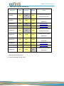
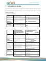
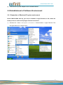
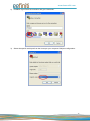
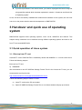
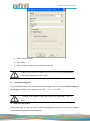
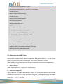
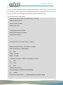
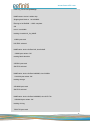
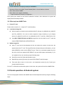
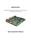
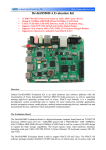
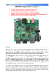
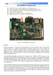
DM3730-EVK Integrated with LCD, USB, CCD/COMS, Audio input/output, S-video, Ethernet, Serial port, TF card interface based on 32-bit microcontroller Quick Operation Manual www.element14.com Version update records: Version Date Description 1.0 2011.7.20 Original version 1.1 2011.8.5 Parts of contents have been amended to avoid ambiguity 1 www.element14.com Contents 1. Overview....................................................................................................................................... 3 1.1 Getting Started Quickly ....................................................................................................... 5 1.2 Development suite .............................................................................................................. 6 2 Quick establishment of development environment ....................................................................... 8 2.1 Establishment of hardware environment ............................................................................ 8 2.2 Establishment of Software Environment ............................................................................. 9 2.2.1 Preparation of Windows XP system environment .................................................... 9 2.2.2 Notes of operating system image file ......................................................................11 3 Handover and quick use of operating system ............................................................................. 12 3.1 Quick operation of Linux system ....................................................................................... 12 3.1.1 Boot-up from TF card.............................................................................................. 12 3.1.2 Boot-up from NAND Flash ...................................................................................... 16 3.2 Quick operation of WinCE system .................................................................................... 19 3.2.1 Boot-up from TF card.............................................................................................. 19 3.2.2 Boot-up from NAND Flash ...................................................................................... 21 3.3 Quick operation of Android system ................................................................................... 21 Customer Service.................................................................................................................... 25 Technical Support.................................................................................................................... 25 Notes ....................................................................................................................................... 25 2 www.element14.com 1. Overview The primary purpose of this Document is to enable the user to know the development environment of software and hardware of DM3730-EVK quickly, and help the user to get into the product development or learning stage faster. 1) 2) This Document mainly has the following parts: a) How to use documents and CD data quickly; b) Description on hardware components of the evaluation board and suite configuration; c) Description on default configuration of software and hardware of the evaluation board; d) Quick establishment of the development environment of the evaluation board; e) Handover and quick use of Linux/wince/Android operating systems. Factory default configuration of DM3730-EVK evaluation board a) Configuration of hardware DM3730-EVK default factory configuration: no welding, 2GB, 4-bit, iNAND, no RTC cell. b) Factory-setting parameters of software DM3730-EVK evaluation board preferably boots from TF card by default, and boots from NANDFLASH if no TF card is inserted. NANDFLASH is installed by default with linux2.6.32 operating system and 4.3-inch screen driver. TF card is installed by default with winCE6.0 operating system and 4.3-inch screen driver. 3 www.element14.com 3) DM3730-EVK optional modules list: Modules Linux Android WinCE YES* NO YES* Notes Provided with CD-ROM on VGA8000 Development board Provided with CD-ROM WF8000-U YES* YES* YES# Separately GPRS8000-S YES* NO YES* Download here GPS8000-S YES* YES* YES* Download here CAM8000-A YES* NO YES* Provided with CD-ROM on Development board Provided with CD-ROM CAM8000-D YES# YES# YES* Separately Provided with CD-ROM CAM8100-U YES* YES* YES# Separately CDMA8000-U YES* YES* YES# Download here WCDMA8000-U YES* YES* YES# Download here COM8010-S YES* YES* NO Provided with CD-ROM Separately * = Provided with Source Code # = Not Provided with Source Code 4 www.element14.com 1.1 Getting Started Quickly This section will tell the user how to understand and use DM3730-EVK better and faster through this DM3730-EVK Quick Operation Manual. For more information please refer to the listed document and location. For hardware development: Hardware system Introduce CPU, expanded chip and hardware interface User Manual->2 Hardware System CPU Datasheet Know principle and configuration of DM37x/AM37x CD->\HW design\datasheet\CPU\ Schematic diagram of DM3730-EVK Know hardware principle of DM3730-EVK CD->\HW design\schematic Dimensional drawing of DM3730-EVK Refer to the actual length and height of DM3730-EVK to bring convenience for opening die User Manual->Appendix->Appendix One For software development: Establish testing environment To connect with external hardware devices, set serial port terminals and boots the system Quick Operation Manual->2 Hardware Settings 3 Software Settings Test functionality of interface Test the interface of the board carrier through the operating system User Manual ->3.8.1 Testing DEMO demonstration Establish a DEMO demonstration system (Android, DVSDK) User Manual->3.8.2.1 Android Demonstration System 3.8.2.2 DVSDK Demonstration System Linux developing and compilation environment User Manual -> 3.4.1 Establishment of Developing Environment WinCE developing and compilation environment User Manual->4.4.1 Installation of Compilation Tool 4.4.2 Establishment of Developing Environment Recompile Linux system image User Manual->3.4.2 System Compilation Recompile WinCE system image User Manual->4.4.3 Sysgen & BSP Compilation Refer to introduction of Linux driver and related driver User Manual->3.5 Driver Introduction Establish developing and compilation environment Recompile system image Software development 5 www.element14.com development process 3.6 Driver Development Refer to introduction of WinCE driver and related driver development process User Manual -> 4.4.4 Driver Introduction For marketing: Hardware system CPU feature, board carrier interface data User Manual->2 Hardware System Know basic Linux software components and features, and purpose of compilation tool User Manual->3.2 Software Resources 3.3 Software Features Know basic WinCE software components and features, and purpose of compilation tool User Manual->4.2 Software Resources 4.3 Features Dimensional drawing of DM3730-EVK Refer to the actual length and height of DM3730-EVK to bring convenience for opening die User Manual->Appendix->Appendix One DEMO demonstration Establish a DEMO demonstration system (Android, DVSDK) User Manual->3.8.2.1 Android Demonstration System 3.8.2.2 DVSDK Demonstration System About Linux / WinCE software For learning personnel: It is suggested to browse each section in each chapter of this Manual in order. 1.2 Development suite DM3730-EVK provides two configuration modes: Standard Configuration and Full Configuration (4.3-inch or 7-inch), the specific accessories for configuration are as follows: Standard Configuration DM3730-EVK evaluation board 2GB TF card Serial port line (DB9-DB9) 5V@2A power adapter USB main data line (A type male to mini-B type male) USB slave data line (A type female to mini-A type female) Crossover cable 6 www.element14.com HDMI to DVI-D data line S-Video cable Full configuration Standard configuration of DM3730-EVK evaluation suite 4.3-inch LCD display screen or 7-inch display screen (with touch screen) Assorted DVD CD DM3730-EVK Quick Operation Manual DM3730-EVK User Manual Schematic Diagram of DM3730-EVK Hardware, Board Carrier Chip Datasheet Development Kit of DM3730-EVK Software (Linux/WinCE/Android) 7 www.element14.com 2 Quick establishment of development environment 2.1 Establishment of hardware environment Please establish the hardware environment according to the following steps: 1) Connect serial port for communication Use serial cable to connect the debugger serial port and PC serial port of DM3730-EVK. 2) Connect TFT-LCD Connect your 4.3-inch/7-inch TFT-LCD to the TFT-LCD interface J9. 3) Insert TF card If you want to boot and operate WINCE6.0 operating system from TF card, please insert the TF card into the TF card slot J3 of DM3730-EVK. 8 www.element14.com 4) Connect the 5V power adapter to the evaluation board 2.2 Establishment of Software Environment 2.2.1 Preparation of Windows XP system environment Before DM3730-EVK boot-up, you need to establish a HyperTerminal on PC; follow the below process in order to setup Hyper Terminal connection: 1) Windows XP -> Start -> All Programs -> Accessories -> Communication -> Hyper Terminal. Find the HyperTerminal, as shown below: 9 www.element14.com 2) Establish HyperTerminal connection and give commands: 3) Select the specific serial port from the list as per your computer COM port configuration: 10 www.element14.com 4) Set parameters for serial port connection as follows: 5) So we have successfully established a Hyper Terminal connection with PC serial port: 2.2.2 Notes of operating system image file Skip this step if you have purchased 4.3-inch touch screen. 11 www.element14.com If you have purchased 7-inch touch screen, you need to reprogram the kernel image file using specified method which has been explained in section 3 “Handover and Quick Use of Operating system”. So far, we have successfully establishment software and hardware for the system, the user now can turn on the power switch to start the development on DM3730-EVK. 3 Handover and quick use of operating system DM3730-EVK supports three operating systems, Linux 2.6.32, WINCE6.0 and Android. This chapter mainly introduces how to handover among different operating systems and how to use from TF card and NANDFLASH. 3.1 Quick operation of Linux system 3.1.1 Boot-up from TF card Assorted TF card of DM3730-EVK is installed by default with WINCE6.0 + 4.3-inch screen driver. Follow the following steps to Boot-up from TF card 1) Format TF We recommend to use HP USB Disk Storage Format Tool 2.0.6 to format the Tf card, you can download this tool from this link: http://www.embedinfo.com/english/download/SP27213.exe Follow the followwing steps to format TF card: a) Insert TF card into the PC card reader. b) Open HP USB Disk Storage Format Tool, a new format window will pop up as below: 12 www.element14.com c) Select “FAT32” format. d) Click “Start”. e) Wait to finish formatting, once completed click “OK”. Please do not use this formatting tool if you use a TF card with partitions, as it will clear partitions of the TF card. 2) Load kernel image file Copy all the files from the CD under the folder linux/image to the TF card, and rename uImage_xx as uImage according to your display device LCD (4.3",7")or VGA. uImage_xx is subject to LCD used by the user, specifically, (4.3,7, VGA). 3) Enter into the system After inserting the TF card in the slot, connect the debugger serial port and turn ON the power to boot, following information will be displayed: 13 www.element14.com 60 Texas Instruments X-Loader 1.47 (Sep 27 2011 - 15:53:45) DM3730_EVK xM Rev A Starting X-loader on MMC Reading boot sector 1153680 Bytes Read from MMC Starting OS Bootloader from MMC... Starting OS Bootloader... U-Boot 2010.06-rc1-svn (Sep 27 2011 - 14:54:40) OMAP34xx/35xx-GP ES2.1, CPU-OPP2 L3-165MHz DM3730_EVK board + LPDDR/NAND I2C: ready DRAM: 512 MiB NAND: 512 MiB *** Warning - bad CRC or NAND, using default environment In: serial Out: serial Err: serial DM3730_EVK xM Rev A Die ID #065400029e3800000168263d0600900a Net: dm9000 Hit any key to stop autoboot: 0 mmc1 is available reading boot.scr 14 www.element14.com ** Unable to read "boot.scr" from mmc 0:1 ** reading uImage 2551588 bytes read reading ramdisk.gz 7686374 bytes read Booting from mmc ... ## Booting kernel from Legacy Image at 80300000 ... Image Name: Image Type: Data Size: Linux-2.6.32 ARM Linux Kernel Image (uncompressed) 2551524 Bytes = 2.4 MiB Load Address: 80008000 Entry Point: 80008000 Verifying Checksum ... OK Loading Kernel Image ... OK OK Starting kernel ... Uncompressing Linux.................................................................................................................................................. ............. done, booting the kernel. Linux version 2.6.32 (luofc@TIOP) (gcc version 4.4.0 (GCC) ) #1 Mon Mar 14 10:08:34 CST 2011 ……… ……… Remounting root file system... mount: mounting /dev/root on / failed: Invalid argument mount: mounting /dev/root on / failed: Invalid argument root: mount: mounting rootfs on / failed: No such file or directory root: mount: mounting usbfs on /proc/bus/usb failed: No such file or directory 15 www.element14.com Setting up IP spoofing protection: rp_filter. Configuring network interfaces... udhcpc (v1.11.3) started Sending discover... udhcpc: sendto: Network is down Sending discover... udhcpc: sendto: Network is down INIT: Entering runlevel: 5 Starting syslogd/klogd: done .-------. | | | | | | |-----.-----.-----.| | | | .-. | __ | | | | .----..-----.-----. ---'| '--.| .-'| | | |--- || --'| | | ' | | | | '---'---'--'--'--. |-----''----''--' '-----'-'-'-' -' | '---' The Angstrom Distribution DM3730_EVK ttyS2 Angstrom 2008.1-test-20090127 DM3730_EVK ttyS2 DM3730_EVK login: (Just input “root”) 3.1.2 Boot-up from NAND Flash DM3730-EVK evaluation board default NANDFLASH is installed with linux + 4.3-inch screen display. it can be booted without connecting TF card once it’s powered on or reset. Follow the steps to copy new image from TF card to NandFlash to boot-up from NANDFLASH: 1) Format TF card Please refer to section 3.1.1 steps for TF card formatting. 2) Load kernel image file Copy x-load.bin.ift_for_NAND,flash-uboot.bin,uImage_xx,ubi.img image files from the CD under the folder linux/image to the TF card, and rename uImage_xx as uImage according to your display device LCD (4.3",7")or VGA. 16 www.element14.com 3) Update image file You can update the NandFlash boot-up image with the help of “u-boot” using TF card. Insert the TF card having system images into the development board slot. Now power ON to boot, press any key to enter into the uboot during second read and execute the following steps. The boot-up interface shown below: Texas Instruments X-Loader 1.47 (Sep 27 2011 - 15:53:45) DM3730_EVK xM Rev A Starting X-loader on MMC Reading boot sector 1153680 Bytes Read from MMC Starting OS Bootloader from MMC... Starting OS Bootloader... U-Boot 2010.06-rc1-svn (Sep 27 2011 - 14:54:40) OMAP34xx/35xx-GP ES2.1, CPU-OPP2 L3-165MHz DM3730_EVK board + LPDDR/NAND I2C: ready DRAM: 512 MiB NAND: 512 MiB *** Warning - bad CRC or NAND, using default environment In: serial Out: serial Err: serial DM3730_EVK xM Rev A Die ID #22e800211e3000000158ed8408008020 Net: dm9000 Hit any key to stop autoboot: 0 (Press any key to enter the u-boot) 17 www.element14.com DM3730_EVK # run updatesys NAND erase: device 0 whole chip Skipping bad block at 0x1c9c0000 Erasing at 0x1ffe0000 -- 100% complete. OK mmc1 is available reading x-load.bin.ift_for_NAND 11000 bytes read HW ECC selected NAND write: device 0 offset 0x0, size 0x2af8 12288 bytes written: OK reading flash-uboot.bin 230764 bytes read SW ECC selected NAND write: device 0 offset 0x80000, size 0x3856c 231424 bytes written: OK reading uImage 2561868 bytes read SW ECC selected NAND write: device 0 offset 0x280000, size 0x27174c 2562048 bytes written: OK reading ubi.img 7602176 bytes read 18 www.element14.com SW ECC selected NAND write: device 0 offset 0x680000, size 0x740000 7602176 bytes written: OK DM3730_EVK # Once completed, led lamp sys on the board will flicker to prompt successful programming, otherwise programming failed. After successful updating, pull the TF card out, and reboot the evaluation board to boot the system from NANDFLASH. In case of failed programming, please execute the above mentioned steps again. 3.2 Quick operation of WinCE system TF card in the DM3730-EVK evaluation board suite comes with default WINCE6.0 + 4.3-inch screen driver. 3.2.1 Boot-up from TF card 1) Format TF card Please refer to section 3.1.1 steps for TF card formatting. 2) Load kernel image file All the images are located under sub-folder WinCE_6/image, lcd_800x480, lcd_480x272 and DVI_1280x720. You need to select respective image according to your display device, lcd_480x272 for LCD 4.3", lcd_800x480 for LCD 7", and DVI_1280x720 for VGA. 3) Copy MLO, EBOOTSD.nb0 and NK.bin image files from the folder to the TF card. Update image file Insert TF card in to the development kit slot and reboot the system. At this time, the system boots from TF card. The HyperTerminal will output boot print information and display the following contents: 60 Texas Instruments Windows CE SD X-Loader for EVM 3730 Built Mar 23 2011 at 08:31:15 Version 6.15.00 open ebootsd.nb0 file Init HW: controller RST SDHC: 1 bit mode SDCARD: reqested speed 1000000, actual speed 1000000 19 www.element14.com Using 4 bit mode SDHC: 4 bit mode SDCARD: reqested speed 25000000, actual speed 24000000 read ebootsd.nb0 file jumping to ebootsd image Microsoft Windows CE Bootloader Common Library Version 1.4 Built Mar 22 2011 18:45:08 Texas Instruments Windows CE EBOOT for Mistral OMAP EVM, Built Mar 23 2011 at 08:31:11 EBOOT Version 1.1, BSP 6.15.00 TI DM3730 Version 0x2b89102f (unknown) TPS659XX Version 0x10 (ES1.1) System ready! Preparing for download... INFO: Predownload.... WARN: Boot config wasn't found, using defaults INFO: SW4 boot setting: 0x2f >>> Forcing cold boot (non-persistent registry and other data will be wiped) <<< Hit space to enter configuration menu 1... Init HW: controller RST SDHC: 1 bit mode SDCARD: reqested speed 1000000, actual speed 1000000 Using 4 bit mode SDHC: 4 bit mode SDCARD: reqested speed 25000000, actual speed 24000000 BL_IMAGE_TYPE_BIN Download file information: ----------------------------------------------------------[0]: Address=0x80101000 Length=0x022a14e4 Save=0x80001000 ----------------------------------------------------------Download file type: 1(You may wait for a longer time here as the system boots from TF card) rom_offset=0x0. ImageStart = 0x80101000, ImageLength = 0x22A14E4, LaunchAddr = 0x8010F82C Completed file(s): ------------------------------------------------------------------------------[0]: Address=0x80101000 Length=0x22A14E4 Name="" Target=RAM ROMHDR at Address 80101044h 20 www.element14.com Launch Windows CE image by jumping to 0x8000f82c... Windows CE Kernel for ARM (Thumb Enabled) Built on Oct 20 2009 at 18:39:19 OAL: CPU revision 0xffffffff OAL: CPU L2 Aux register 0x400042 --- High Performance Frequecy is 32768 khz--Here system has entered into the WinCE calibration interface, after calibration the system will display WinCE desktop interface. 3.2.2 Boot-up from NAND Flash 1) Format TF card Please refer to section 3.1.1 steps for TF card formatting. 2) Load kernel image file All the images are located under sub-folder WinCE_6/image, lcd_800x480, lcd_480x272 and DVI_1280x720. You need to select respective image according to your display device, lcd_480x272 for LCD 4.3", lcd_800x480 for LCD 7", and DVI_1280x720 for VGA. Copy MLO, EBOOTSD.nb0 and NK.bin image files from the folder to the TF card and rename EBOOTNAND.nb0 as EBOOTSD.nb0. 3) Update image file Insert TF card into the development kit slot and reboot the system. At this time, the system boots from TF card. The HyperTerminal will output boot print information, you can press [SPACE] to enter into the EBOOT menu. There is an automatic update key [k] in the menu, which can update XLDR, EBOOT, logo and NK images automatically, or you can update one by one according as per following steps: Press [5] to enter the Flash administration menu. Respectively press [a], [b] and [c] to write XLDR, EBOOT and NK images. Then press [0] to return to main menu, and respectively press [2], [4], [7] and [y] to change the boot devices. Pull out TF card and then reboot the system. At this time, the system will boot from NAND Flash. 3.3 Quick operation of Android system The user can program Android to the NAND Flash of the development board by using the following steps. 21 www.element14.com Note: At present, Android only supports boot-up from NAND Flash. 1) Format TF card Please refer to section 3.1.1 steps for TF card formatting 2) Load kernel image file Copy all files from CD under the folder /linux/demo/Android/image to the TF card, and rename uImage_xx as uImage according to your display device LCD (4.3",7"). At present, Android does not support VGA display mode. 3) Update image file Insert the TF card in to the development board slot, connect the debugging serial port and turn ON the power to boot, information displayed as follows; 60 Texas Instruments X-Loader 1.47 (Sep 20 2011 - 16:18:31) DM3730_EVK xM Rev A Starting X-loader on MMC Reading boot sector 1153712 Bytes Read from MMC Starting OS Bootloader from MMC... Starting OS Bootloader... U-Boot 2010.06-rc1-svn (Sep 27 2011 - 14:57:19) OMAP34xx/35xx-GP ES2.1, CPU-OPP2 L3-165MHz DM3730_EVK board + LPDDR/NAND I2C: ready 22 www.element14.com DRAM: 512 MiB NAND: 512 MiB *** Warning - bad CRC or NAND, using default environment In: serial Out: serial Err: serial DM3730_EVK xM Rev A Die ID #3a7e00229e3800000168263d0402302f NAND erase: device 0 whole chip Erasing at 0x1ffe0000 -- 100% complete. OK mmc1 is available reading x-load.bin.ift_for_NAND 10892 bytes read HW ECC selected NAND write: device 0 offset 0x0, size 0x2a8c 12288 bytes written: OK reading flash-uboot.bin 1152260 bytes read SW ECC selected NAND write: device 0 offset 0x80000, size 0x119504 1153024 bytes written: OK reading uImage 2572792 bytes read 23 www.element14.com SW ECC selected NAND write: device 0 offset 0x280000, size 0x2741f8 2574336 bytes written: OK reading ubi.img (You may wait for a longer time here as the system boots from TF card) 79036416 bytes read SW ECC selected NAND write: device 0 offset 0x680000, size 0x4b60000 79036416 bytes written: OK Once finished, led lamp sys on the board will flicker to prompt the successful programming, at this time pull out the TF card, turn power on and boot again to enter into the Android operation system. 24 www.element14.com Customer Service Please contact Premier Farnell local sales and customer services staffs for the help. Website: http://www.farnell.com/ Technical Support Please contact Premier Farnell local technical support team for any technical issues through the telephone, live chat & mail, or post your questions on the below micro site, we will reply to you as soon as possible. Centralized technical support mail box: [email protected] Community: http://www.element14.com/community/community/knode/dev_platforms_kits Please visit the below micro site to download the latest documents and resources code: http://www.element14.com/community/community/new_technology/at91sam9g45-evk Notes This board was designed by element14’s design partner- Embest, you can contact them to get the technical support as well. Marketing Department: Tel: +86-755-25635656 / 25636285 Fax: +86-755-25616057 E-mail:[email protected] Technical Support: Tel: +86-755-25503401 E-mail: [email protected] URL: http://www.armkits.com 25