1
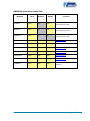
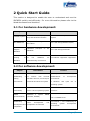
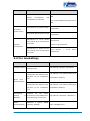
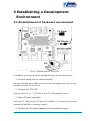
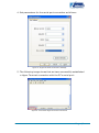
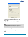
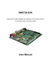
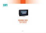
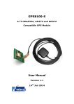
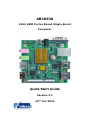
SBC8530 1GHz ARM Cortex Based Single Board Computer Quick Start Guide Version 2.1 22nd Jan 2014 Copyright Statement: SBC8530, CAM8000-A, CAM8000-D, GPRS8000-S, GPS8000-S, WCDMA8000-U, CDMA8000-U, WF8000-U, CAM8100-U, and VGA8000 and their related intellectual property are owned by Shenzhen Embest Technology Co., Ltd. Shenzhen Embest Technology has the copyright of this document and reserves all rights. Any part of the document should not be modified, distributed or duplicated in any approach and form without prior written permission issued by Embest Technology Co., Ltd. Revision History: Version Date Description 1.0 15/09/2011 Original Version 1.1 19/12/2012 Added LVDS support and changed the Linux display method configuration 2.1 22/01/2014 Localisation Table of Contents 1 Product Overview .............................................................. 1 2 Quick Start Guide .............................................................. 3 2.1 For hardware development: ..............................................3 2.2 For software development: ...............................................3 2.3 For marketing: ................................................................4 2.4 For Education:.................................................................5 2.5 Kit Contents ....................................................................5 3 Establishing a Development Environment.......................... 6 3.1 Establishment of hardware environment .............................6 3.2 Establishment of a Software Environment ...........................7 3.2.1 Environment preparation for Windows XP ..................................... 7 4 Operating System Quick Start Guide ............................... 10 4.1 Quick operation of the Linux system ................................ 10 4.1.1 Booting from a TF card ............................................................. 10 4.1.2 Boot-up from NAND Flash ......................................................... 14 4.2 Quick Operation of the WinCE system .............................. 16 4.2.1 Boot-up from the TF card .......................................................... 16 4.2.2 Boot-up from NAND Flash ......................................................... 18 4.3 Quick operation of the Android system ............................. 19 Appendix 1: ESD Precautions & Handling Procedures ......... 22 Appendix 2: Technical support & Warranty ........................ 23 2.1 Technical support service ................................................ 23 2.2 Maintenance service clause ............................................. 24 2.3 Basic guidelines for protection and maintenance of LCDs .... 25 2.4 Value Added Services ..................................................... 26 1 Product Overview The primary purpose of this Document is to enable the user to learn the development environment (software and hardware) of the SBC8530 quickly, and to help the user reach the product development or learning stage faster. This Document consists mainly of the following parts: Quick guide to documentation and CD data; Description of the hardware components of the evaluation board and suite configuration; Description of the default configuration of both software and hardware of the evaluation board; Quick establishment of a development environment for the evaluation board; Quick start/user guide for the Linux/WinCE/Android operating systems; Factory default configuration of the SBC8530 evaluation board Factory-setting parameters of software: SBC8530 evaluation board boots from a TF card by default, and boots from NAND Flash if no TF card is inserted. NAND Flash is by default, preinstalled with a linux2.6.32 operating system and the default display device is a 4.3” screen. The supplied TF card is by default, preinstalled with a WinCE6.0 operating system. Page | 1 SBC8530 optional modules list: Modules Linux Android WinCE Location CD-ROM provided with VGA8000 YES* NO YES* WF8000-U YES* NO YES CAM8000-A YES* NO NO CAM8000-D YES* YES YES* Download here CAM8100-U YES* YES* YES CD-ROM Provided Separately CDMA8000-U YES* YES* YES Download here GPS8000-S YES* YES* YES* Download here GPRS8000-S YES* YES* YES* Download here WCDMA8000-U YES* YES* YES Download here LVDS8000 YES* YES* YES* Development board CD-ROM provided with Development board CD-ROM provided with Development board Available on DVD-ROM and on website *=Source code provided Page | 2 2 Quick Start Guide This section is designed to enable the user to understand and use the SBC8530 quickly and efficiently. For more information please refer to the listed documents and locations. 2.1 For hardware development: Subject Hardware system Introduction to CPU, expanded User Manual->Chapter 2 Hardware chip and hardware interface System the DM37x Schematic of SBC8530 Dimensional drawing Location Principles and configuration of CPU Datasheet diagram Information Hardware principles of the SBC8530 CD->\HW design\datasheet\CPU\ CD->\HW design\schematic Contains the actual dimensions of SBC8530 of the SBC8530 for User Manual->Appendix->Appendix I manufacturing convenience 2.2 For software development: Subject Information Location Quick Operation Manual->2 Quick Establishing a To connect with external testing hardware devices, set serial port environment terminals and boot the system establishment of development environment 3 Handover and quick use of operating system Test interface Test the interface of the board User Manual ->3.8.2 Various Test functionality carrier via the operating system scenarios DEMO Establish (demonstration) (Android, DVSDK) Establishing Linux a development and compilation a system development compilation environment DEMO User Manual->3.8.3.1 Android Demo 3.8.3.2 DVSDK Demo and User Manual -> 3.4.1 Establishing an operating system development environment Page | 3 Subject Information Location User Manual->4.4.1 Installation of environment WinCE development and compilation environment IDE 4.4.2 Extract BSP and project files to IDE Recompile Linux system image Recompile system image Recompile WinCE system image Introduction to Linux drivers and related driver development processes Software development User Manual->3.4.2 System Compilation User Manual->4.4.3 Sysgen & BSP Compilation User Manual->3.5 Driver Introduction 3.6 Driver Development Introduction to WinCE drivers and related driver development processes User Manual -> 4.4.4 Driver Introduction 2.3 For marketing: Subject Information Hardware system Location CPU features, board carrier interface data Teaches basic Linux software components and features, and purposes of the compilation About Linux / WinCE software tool Teaches basic WinCE software components and features, and purposes of the compilation tool Dimensional drawing Contains of the the SBC8530 manufacturing convenience DEMO Establish (demonstration) (Android, DVSDK) system User Manual->3.2 Software Resources 3.3 Software Features User Manual->4.2 Software Resources 4.3 Software Features actual dimensions of the SBC8530 for a User Manual->Chapter 2 Hardware DEMO User Manual->Appendix->Appendix I User Manual->3.8.3.1 Android Demo 3.8.3.2 DVSDK Demo Page | 4 2.4 For Education: It is suggested that students and others hoping to learn the functions of the SBC8530 should browse each section in each chapter of both this document and the User Manual in order. 2.5 Kit Contents SBC8530 evaluation board 2GB TF card Serial cable (DB9-to-DB9) 5V, 2A power adapter USB main data line ( type A male to type mini-B male) USB slave data line (type A female to type mini-A male) Crossover Ethernet cable HDMI to DVI-D cable S-Video cable WiFi antenna Optional 4.3” LCD display screen or 7” display screen (with touch screen) DVD/CD including: o SBC8530 Quick Start Guide o SBC8530 User Manual o Schematic Diagram of the SBC8530 Hardware o Board Carrier Chip Datasheet o Development Kit software for the SBC8530 (Linux/WinCE/Android) Page | 5 3 Establishing a Development Environment 3.1 Establishment of hardware environment Figure 1: SBC8530 Hardware Connections A hardware environment can be established using the following steps: 1. Connect serial port for communication Use the provided serial cable to connect the debugger serial port on the SBC8530 and the PC serial port. 2. Connect the TFT-LCD Connect your 4.3” or 7” TFT-LCD to the TFT-LCD interface (J401). 3. Insert TF card (optional) Insert the TF card into the TF card slot (CON301) if you wish to boot and operate the WinCE6.0 operating system. 4. Connect the 5V power adapter to the evaluation board Page | 6 3.2 Establishment of a Software Environment 3.2.1 Environment preparation for Windows XP Before boot-up of the SBC8530, you need to configure HyperTerminal on the PC, follow the process below in order to setup a Hyper Terminal connection: 1. From the desktop click: Start All Programs Accessories Communication Hyper Terminal As shown in the following image: Figure 2: HyperTerminal Location on Windows XP Page | 7 2. Establish a new HyperTerminal connection: Figure 3: Setting HyperTerminal Connection Name & Icon 3. Select the specific serial port from the list as per your computers COM port configuration: Figure 4: HyperTerminal COM Port Settings Page | 8 4. Set parameters for the serial port connection as follows: Figure 5: HyperTerminal Connection Settings 5. The following image shows that we have successfully established a Hyper Terminal connection with the PC’s serial port: Figure 6: Successful HyperTerminal Connection Page | 9 4 Operating System Quick Start Guide The SBC8530 supports three operating systems, Linux 2.6.32, WinCE6.0 and Android. This chapter mainly introduces how to switch among different operating systems and how to boot from both the TF card and NAND Flash. 4.1 Quick operation of the Linux system 4.1.1 Booting from a TF card The TF card provided with the SBC8530 is supplied preinstalled with a WinCE6.0 operating system. The steps below show the process of booting-up from a TF card: 1. Format the MMC/SD card We recommend the HP USB Disk Storage Format Tool 2.0.6 to format a TF card, this is available from: http://www.embest-tech.com/resource/download/HP-USB-Disk-St orage-Format-Tool.rar Use the following steps to format a TF card: a. Insert a TF card into the PC card reader. b. Open the HP USB Disk Storage Format Tool, a new format window will be displayed as below: Page | 10 Figure 7: HP USB Disk Storage Format Tool Settings c. Select “FAT32” from the file system drop down box. d. Click “Start”. e. Wait until formatting is complete then click “OK”. Note: HP USB Disk Storage Format Tool will erase the partitions of TF card. Use other format tool may cause the failure of the TF card booting 2. Load kernel image file Copy all files under the directory linux/image to the TF card. Connect the TF card, power on and boot it, the serial port information will be displayed as follows: Page | 11 Note: Using 4.3” LCD output as default, if you require another display device, please refer to the User Manual 60 Texas Instruments X-Loader 1.47 (Feb 17 2011 - 17:33:15) SBC8530 xM Rev A Starting X-loader on MMC Reading boot sector 1153472 Bytes Read from MMC Starting OS Bootloader from MMC... Starting OS Bootloader... U-Boot 2010.06-rc1-svn (Mar 04 2011 - 10:18:34) OMAP34xx/35xx-GP ES2.0, CPU-OPP2 L3-165MHz OMAP3 SBC8530 board + LPDDR/NAND I2C: ready DRAM: 512 MiB NAND: 512 MiB *** Warning - bad CRC or NAND, using default environment In: serial Out: serial Err: serial SBC8530 xM Rev A Die ID #22e800211e3000000158ed8408008020 Net: dm9000 Hit any key to stop autoboot: 0 mmc1 is available reading boot.scr ** Unable to read "boot.scr" from mmc 0:1 ** reading uImage 2645364 bytes read reading ramdisk.gz 7686374 bytes read Page | 12 Booting from mmc ... ## Booting kernel from Legacy Image at 80300000 ... Image Name: Linux-2.6.32 Image Type: ARM Linux Kernel Image (uncompressed) Data Size: 2645300 Bytes = 2.5 MiB Load Address: 80008000 Entry Point: 80008000 Verifying Checksum ... OK Loading Kernel Image ... OK OK Starting kernel ... Uncompressing Linux....................................................................... ............................................................................ ............ done, booting the kernel. Linux version 2.6.32 (luofc@TIOP) (gcc version 4.4.0 (GCC) ) #1 Mon Mar 14 10:08:34 CST 2011 ……… Remounting root file system... mount: mounting /dev/root on / failed: Invalid argument mount: mounting /dev/root on / failed: Invalid argument root: mount: mounting rootfs on / failed: No such file or directory root: mount: mounting usbfs on /proc/bus/usb failed: No such file or directory Setting up IP spoofing protection: rp_filter. Configuring network interfaces... udhcpc (v1.11.3) started Sending discover... udhcpc: sendto: Network is down Sending discover... udhcpc: sendto: Network is down INIT: Entering runlevel: 5 Starting syslogd/klogd: done .-------. | | | | | | |-----.-----.-----.| | | | .-. | __ | | | | .----..-----.-----. ---'| '--.| .-'| |--- | | || --'| | | ' | | | | '---'---'--'--'--. |-----''----''--' '-----'-'-'-' -' | '---' The Angstrom Distribution SBC8530 ttyS2 Angstrom 2008.1-test-20090127 SBC8530 ttyS2 SBC8530 login:root Page | 13 If HyperTerminal displays the above information this indicates that the Linux system has successfully booted from the TF card. 4.1.2 Boot-up from NAND Flash The SBC8530 evaluation board is provided with a Linux system preinstalled into the NAND Flash, and a default display of 4.3”. The Linux system can be booted without connecting a TF card. If a 7” LCD or other supported display device is required, you need to change the uboot parameters as per the User Manual section 4.8.1 Selecting the display device. If you wish to update the image stored in the NAND Flash, use the following steps: Preparation: 1. Format the TF card to a FAT or FAT32 file system using the HP USB Disk Storage Format Tool. 2. Copy all the image files under /linux/image of the CD to the TF card Update: 3. Insert the TF card which contains the system images into the development board, and then connect the power supply. Press any key on the keyboard to enter the u-boot when the message "Hit any key to stop autoboot" appears: Texas Instruments X-Loader 1.47 (Jan 26 2011 - 08:37:12) SBC8530 xM Rev A Starting X-loader on MMC Reading boot sector 1153472 Bytes Read from MMC Starting OS Bootloader from MMC... Starting OS Bootloader... U-Boot 2010.06-rc1 (10 27 2011 - 10:20:37) OMAP34xx/35xx-GP ES2.0, CPU-OPP2 L3-165MHz OMAP3 SBC8530 board + LPDDR/NAND Page | 14 I2C: ready DRAM: 512 MiB NAND: 512 MiB *** Warning - bad CRC or NAND, using default environment In: serial Out: serial Err: serial SBC8530 xM Rev A Die ID #22e800211e3000000158ed8408008020 Net: dm9000 (Press any key to enter u-boot) Hit any key to stop autoboot: 0 After entering the u-boot command line, input “run updatesys” from the PC keyboard, to start the update process of the system: OMAP3 SBC8530 # run updatesys NAND erase: device 0 whole chip Erasing at 0x1ffe0000 -- 100% complete. OK mmc1 is available reading x-load.bin.ift_for_NAND 10912 bytes read HW ECC selected NAND write: device 0 offset 0x0, size 0x2aa0 12288 bytes written: OK reading flash-uboot.bin 1153472 bytes read SW ECC selected NAND write: device 0 offset 0x80000, size 0x1199c0 1155072 bytes written: OK reading uImage 2645364 bytes read SW ECC selected NAND write: device 0 offset 0x280000, size 0x285d74 2646016 bytes written: OK reading ubi.img 14680064 bytes read Page | 15 SW ECC selected NAND write: device 0 offset 0x680000, size 0xe00000 14680064 bytes written: OK OMAP3 SBC8530 # 4. At this time, the flickering of the LED on the board indicates that the update process has completed; remove the TF card and reboot the system. 5. This uses a 4.3” LCD as default, if you require an alternate display device, please refer to 4.8.1 Selecting the display device in the User Manual 4.2 Quick Operation of the WinCE system The TF card provided with the SBC8530 evaluation board is preinstalled with a WinCE6.0 operating system. 4.2.1 Boot-up from the TF card 1. Format the TF card Please refer to contents of 3.1.1 Booting from a TF Card. 2. Copy runtime image Copy the MLO, EBOOTSD.nb0 and NK.bin image files located in CD\WINCE600\image to the TF card. 3. Boot system Insert the TF card and reboot the system. When the system boots from the TF card, press the space button enter the eboot menu; type [A] to select the LCD / DVI display output, and then type [0] to boot the system. HyperTerminal will display a boot message as below: 60 Texas Instruments Windows CE SD X-Loader for EVM 3730 Built Sep 8 2011 at 16:59:14 Version BSP_WINCE_ARM_A8 1.01.00.03 open ebootsd.nb0 file Init HW: controller RST SDCARD: reqested speed 1000000, actual speed 1000000 SDCARD: reqested speed 25000000, actual speed 19200000 Page | 16 jumping to ebootsd image Microsoft Windows CE Bootloader Common Library Version 1.4 Built Sep 8 2011 09:46:18 Texas Instruments Windows CE EBOOT for OMAP35xx/37xx, Built Sep 8 2011 at 16:59:01 EBOOT Version 0.0, BSP BSP_WINCE_ARM_A8 1.01.00.03 TI OMAP3730 Version 0x00000012 (ES1.2) TPS659XX Version 0x30 (ES1.3) System ready! Preparing for download... INFO: Predownload.... Checking bootloader blocks are marked as reserved (Num = 14) WARN: Boot config wasn't found, using defaults INFO: SW4 boot setting: 0x2f OS partition does not exist!! Formatting flash... Flash format complete! >>> Forcing cold boot (non-persistent registry and other data will be wiped) <<< Hit space to enter configuration menu 5... Hit space to enter configuration menu 4... Hit space to enter configuration menu 3... Hit space to enter configuration menu 2... Hit space to enter configuration menu 1... Init HW: controller RST SDCARD: reqested speed 1000000, actual speed 1000000 SDCARD: reqested speed 25000000, actual speed 19200000 BLSDCardReadLogo: cannot open Logo.bmp BL_IMAGE_TYPE_BIN Download file information: ----------------------------------------------------------[0]: Address=0x80002000 Length=0x01a1c86c Save=0x80002000 ----------------------------------------------------------Download file type: 1 ............................................................................ ............................................................................ ...................................................................rom_offse t=0x0. ..ImageStart = 0x80002000, ImageLength = 0x1A1C86C, LaunchAddr = 0x80012248 Completed file(s): Page | 17 -----------------------------------------------------------------------------[0]: Address=0x80002000 Length=0x1A1C86C Name="" Target=RAM ROMHDR at Address 80002044h Launch Windows CE image by jumping to 0x80012248... Windows CE Kernel for ARM (Thumb Enabled) Built on Oct 20 2009 at 18:39:19 OAL: CPU revision 0x12:DM3730 OAL: CPU L2 Aux register 0x400042 ****Profiler Build**** ---High Performance Frequency is 26000307 hz---- 4.2.2 Boot-up from NAND Flash 1. Format the TF card Please refer to the contents of 3.1.1 Booting from a TF card. 2. Copy the runtime image Copy the MLO, EBOOTNAND.nb0, NK.bin and XLDRNAND.nb0 EBOOTSD.nb0 image files located in CD\WINCE600\image to the TF card, rename EBOOTNAND.nb0 to EBOOTND.nb0. 3. Flashing the image file Insert the TF card and reboot the system. The system will boot from the TF card. HyperTerminal will display a boot message, at this point you can press [SPACE] to enter the EBOOT menu and flash the image to the NAND Flash using the following steps: Press [8] to enter the Flash menu. Press [A], [B] and [C] to write the XLDR, EBOOT and NK images respectively. Press [0] to return to the main menu, and respectively press [2], [4] to select boot from NAND Flash, then type [A] to select the LCD / DVI output mode [7] and [y] to save the Boot setting. Unplug the TF card and reboot the system, then the system will boot from NAND Flash. Page | 18 4.3 Quick operation of the Android system The user can program Android to the NAND Flash of the development board by using the following steps. Note: At present, Android only supports boot-up from NAND Flash. 1. Format the TF card Please refer to section 3.1.1 Booting from a TF card. 2. Load a kernel image file Copy all files from the CD under the folder /linux/demo/Android/image to the TF card, 3. Update the image file a. Insert the TF card into the development board, and then connect the power supply; the debugging tool will display the following information: Texas Instruments X-Loader 1.47 (Feb 17 2011 - 17:33:15) SBC8530 xM Rev A Starting X-loader on MMC Reading boot sector 230740 Bytes Read from MMC Starting OS Bootloader from MMC... Starting OS Bootloader... U-Boot 2010.06-rc1-svn (Mar 4 2011 - 10:18:34) OMAP34xx/35xx-GP ES2.0, CPU-OPP2 L3-165MHz OMAP3 SBC8530 board + LPDDR/NAND I2C: ready DRAM: 512 MiB NAND: 512 MiB Page | 19 *** Warning - bad CRC or NAND, using default environment In: serial Out: serial Err: serial SBC8530 xM Rev A Die ID #22e800211e3000000158ed8408008020 Net: dm9000 Hit any key to stop autoboot: 0 NAND erase: device 0 whole chip Skipping bad block at 0x1c9c0000 Erasing at 0x1ffe0000 -- 100% complete. OK mmc1 is available reading x-load.bin.ift_for_NAND 11000 bytes read HW ECC selected NAND write: device 0 offset 0x0, size 0x2af8 12288 bytes written: OK reading flash-uboot.bin 230740 bytes read SW ECC selected NAND write: device 0 offset 0x80000, size 0x38554 231424 bytes written: OK reading uImage 2551564 bytes read SW ECC selected NAND write: device 0 offset 0x280000, size 0x26ef0c 2551808 bytes written: OK reading ubi.img 74055680 bytes read SW ECC selected NAND write: device 0 offset 0x680000, size 0x46a0000 74055680 bytes written: OK Page | 20 b. The LED on the board will flash after programming is complete, once this happens you can remove the TF card. c. Restart the board to boot the Android OS. d. The default display mode is a 4.3” LCD. This can be changed by referring to 4.8.1 Selecting the Display Device in the User Manual Page | 21 Appendix 1: ESD Precautions & Handling Procedures Please note that the board comes without any case/box and all components are exposed. Therefore, extra attention must be paid to ESD (electrostatic discharge) precautions. To effectively prevent electrostatic damage, please follow the steps below: Avoid carpets in cool, dry areas. Leave development kits in their anti-static packaging until ready to be installed. Dissipate static electricity before handling any system components (development kits) by touching a grounded metal object, such as the system unit unpainted metal chassis. If possible, use antistatic devices, such as wrist straps and floor mats. Always hold an evaluation board by its edges. Avoid touching the contacts and components on the board. Take care when connecting or disconnecting cables. A damaged cable can cause a short in the electrical circuit. Prevent damage to the connectors by aligning connector pins before you connect the cable. Misaligned connector pins can cause damage to system components at power-on. When disconnecting a cable, always pull on the cable connector or strain-relief loop, not on the cable itself. Warning: This is a class A product. In a domestic environment this product may cause radio interference in which case the user may be required to take adequate measures. Page | 22 Appendix 2: Technical support & Warranty Embest Technology Co., Ltd. established in March of 2000, is a global provider of embedded hardware and software. Embest aims to help customers reduce time to market with improved quality by providing the most effective total solutions for the embedded industry. In the rapidly growing market of high end embedded systems, Embest provides comprehensive services to specify, develop and produce products and help customers to implement innovative technology and product features. Progressing from prototyping to the final product within a short time frame and thus shortening the time to market, and to achieve the lowest production costs possible. Embest insists on a simple business model: to offer customers high-performance, low-cost products with the best quality and service. 2.1 Technical support service Embest provides one year of free technical support for all products. The technical support service covers: Embest embedded platform products software/hardware materials Assistance to customers with regards to compiling and running the source code we offer. Troubleshooting problems occurring on embedded software/hardware platforms if users have followed the instructions provided. Judge whether a product failure exists. The situations listed below are not covered by our free technical support service, and Embest will handle the situation at our discretion: Customers encounter issues related to software or hardware during their development process Issues occur when users compile/run the embedded OS which has been modified by themselves. Page | 23 Customers encounter issues related to their own applications. Customers experience problems caused by unauthorised alteration of our software source code 2.2 Maintenance service clause 1. Product warranty will commence on the day of sale and last 12 months provided the product is used under normal conditions 2. The following situations are not covered by the warranty, Embest will charge service fees as appropriate: Customers fail to provide valid proof of purchase or the product identification tag is damaged, unreadable, altered or inconsistent with the product. Products are subject to damage caused by operations inconsistent with their specification; Products are subject to damage in either appearance or function due to natural disasters (flood, fire, earthquake, lightning strike or typhoon) or natural aging of components or other force majeure; Products are subject to damage in appearance or function due to power failure, external forces, water, animals or foreign materials; Products malfunction due to disassembly or alteration of components by customers, or repair by persons or organizations unauthorized by Embest Technology, or alteration from factory specifications, or configured or expanded with components that are not provided or recognized by Embest Technology; Product failures due to the software or systems installed by customers, inappropriate software settings or computer viruses; Products purchased from unauthorized merchants; Page | 24 Embest Technology takes no responsibility for fulfilling any warranty (verbal or written) that is not made by Embest Technology and not included in the scope of our warranty. 3. Within the period of warranty, the cost for sending products to Embest should be paid by the customer. The cost for returning the product to the customer will be paid by Embest. Any returns in either direction occurring after the warranty period has expired should be paid for by the customer. 4. Please contact technical support with any repair requests. Note: Embest Technology will not take any responsibility for products returned without the prior permission of the company. 2.3 Basic guidelines for protection and maintenance of LCDs 1. Do not use finger nails or other hard sharp objects to touch the surface of the LCD 2. Embest recommends purchasing specialist wipes to clean the LCD after long time use, avoid cleaning the surface with fingers or hands as this may leave fingerprints or smudges. 3. Do not clean the surface of the screen with unsuitable chemicals Note: Embest do not supply a maintenance service for LCDs. We suggest the customer immediately checks the LCD once in receipt of the goods. In the event that the LCD does not run or shows no display, the customer should inform Embest within 7 business days of delivery. Page | 25 2.4 Value Added Services We will provide following value added services: Driver development based on Embest embedded platforms for devices such as: serial ports, USB interface devices, and LCD screens. Control system transplantation, BSP driver development, API software development. Other value added services including supply of power adapters and LCD parts. Other OEM/ODM services. Technical training. Please contact Embest with any technical support queries: http://www.embest-tech.com/contact-us.html Page | 26