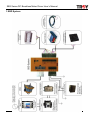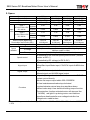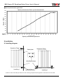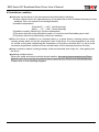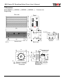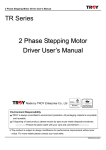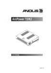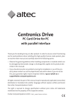
1
SBS Series DC Brushless Motor Driver User’s Manual
SBS Series
Brushless DC Motor Driver
User ’s Manual
Anlagentechnik GmbH
Made by TROY Enterprise Co., Ltd
ISO14001
Certificate No.: 09 104 9351
Environment Responsibility
●
TROY is always committed to environment protection. All packaging material is
●
recyclable and reusable.
If disposing of used product, please recycle by type as per waste disposal procedures.
---------------Protect the green earth with your care and commitment--------------
※The product is subject to design modification for performance improvement without prior
notice. For more details please contact your local seller.
SBS-QM-08E
SBS Series DC Brushless Motor Driver User’s Manual
Contents
1.System diagram
2.Specification……………………………………………………… 1
3.Verifying the product name and accessories……………… 3
4.Function of driver………………………………………………… 5
5.Wiring and operation………………………………………………6
5.1Wiring diagram……………………………………………………6
5.2Noise interference prevention………………………………….7
5.3Signal input and output………………………………………….7
5.4Operation…………………………………………………………...9
5.5Alarm protection function………………………………………10
5.6Connection…………………………………………………… …..11
5.7Parallel operation and multi-speed control………………….12
6.Installation…………………………………………………………...15
6.1Installing diagram…………………………………………… ……15
6.2Installation conditions……………………………………………16
7.Dimension……………………………………………………………17
※For any operational or technical question with the product, please contact us for professional
service「0800-450-168」during our business hours.
SBS-QM-08E
SBS Series DC Brushless Motor Driver User’s Manual
Precautions
Precautions for using
1.Thank you for purchasing TROY products. Please read this user’s manual thoroughly before
installing and operating the driver, and always keep the manual where it is readily available.
2.The products described in this manual has been designed and manufactured for use in
industrial machinery, and must not be used for any other purpose. We are not responsible for
any damage caused through failure to observe this warning.
3.Check that the motor, driver and any accessories are all present. If an accessory is missing or
damaged, contact the nearest our branches.
4.Never disassemble the motor and driver. Damage or performance impairment may result.
Disassembly voids all warranties.
Precautions for maintenance
Check the ambient environments, clean the system equipment to remove dust and tighten the
screws periodically. Also pay attention to the followings.
1. Contact us when repairs become necessary.
2. Since the temperature of the frame of the driver can rise high, be careful when conducting
maintenance work or inspection work.
Precautions for warranty period
Within the period of one year after delivery of the system equipment, when failures occurring
from design error or fabrication error attributable to the manufacture side occur, we will be
repairing the failure free of charge within the reparable range or will replace with substitute.
(We cannot hold ourselves responsible for breakage and accidents occurring from your use
beyond the specified range described in this document.)
Precautions for disposal
When disposing of the driver and the motor, treat them as ordinary industrial waste.
SBS-QM-08E
SBS Series DC Brushless Motor Driver User’s Manual
1.SBD System
SBS-QM-08E
SBS Series DC Brushless Motor Driver User’s Manual
2. Specs
Motor output
Round shaft
Pinion shaft
Drive model
Max
-Type 1
Current
AC110~115V±15%
Rated
50 / 60 Hz
Input
Current
Power
Max
-Type 2
Current
AC220~230V±15%
Rated
50 / 60 Hz
Current
Starting torque (Kgcm/Nm)
Rated Torque (Kgcm/Nm)
Permissible load inertia (GD2)
Speed range
To load
Speed
To voltage
variation
To temp.
Speed control
20W
6B20S-□N
6SBS020P-□N
SBD020-□
40W
6B040S-□N
6BS040P-□N
SBD040-□
60W
9B060S-□N
9B060P-□N
SBD060-□
90W
9B090S-□N
9B090P-□N
SBD090-□
2.4A
2.4A
2.5A
2.9A
0.59A
0.99A
1.48A
1.93A
1.7A
1.7A
1.7A
1.7A
0.33A
0.56A
0.82A
1.05A
4.5/0.45
6.5/0.65
1.5/0.15
2.5/0.25
3.0/0.30
5.0/0.50
1.0/0.10
2.0/0.20
39.42Kgcm2
54.23 Kgcm2
14.01Kgcm2
9.55Kgcm2
250~2000rpm (Rated toque output)
-1% (at 2000 rpm with no-load ~rated load)
±2% (Power voltage variation: -1 type is±15%,-2 type is±10% at
2000rpm under no load)
±2% (0~40℃, at 2000 rpm with no-load)
●Controlled by the external speed potentiometer (Variable
resistor at 20 kΩ).
●Controlled by DC voltage (at DC 0~5V/).
Signal input
Signal output
Functions
●Photocoupler input interface.
●Stop/Start input.Brake input,.CW/CCW input.ALARM clear
input
●Open Collector output interface.
●Speed signal and ALARM signal output
●Input/output signal contact which can connect to PLC I/O
contact control directly
●Motor flat torque output within 250~2000RPM
●It has instantaneous brake stop,clockwise/
counterclockwise,natural stop,slow start/slow down
●When brake stop it has electrical holding torque function
The protection function activated,motor will stop and the
「ALARM」red light lit up during motor over load/over
speed/over heat/controller over voltage/controller low
voltage/motor cable broken
※Please fill the power in the box-□,”1”indicates AC110~115V±15%;”2” indicates AC220V~230V
±15%
1
SBS-0S-V07E
SBS Series DC Brushless Motor Driver User’s Manual
2.1Motor/Controller specs
Item
Controller
Motor
Insulating resistance
When tested with DC500V high
resistance meter, the
resistance between power, F.G
ground, and I/O contact
terminal is over 100MΩ.
When tested with DC500V high
resistance meter, the resistance
between wires and motor case is
over 100MΩ.
No abnormal condition when
supplying 1.8KV/60Hz voltage
between the power and the F.G
No abnormal condition when
Dielectric strength
ground connection terminal and
supplying 1.8KV/60Hz voltage
3KV/60Hz voltage between the
continued 1 sec.
power and I/O connection
terminal for one minute.
0~40℃
0~50℃
Temperature
Environmental
Humidity
Within 85%
conditions
Atmosphere
No corrosive gases,dust,water or oil
2
SBS-0S-V07E
SBS Series DC Brushless Motor Driver User’s Manual
3.Verifying the combination when purchased
Upon opening the package, verify that the items listed below are included then install, wring and
operating. If there is any problem please contact our branch.
3.1 Verifying the content of package
Round type/Pinion type ※Note:The pinion type has to attached with「GEARHEAD」then it can install
Item
Quantity
Controller
1
Mounting plate
2
(Attached with flat screwsX4PCS)
Variable resistor
1
1
Signal insulated cable(For variable resistor)
Connector (10 pins&4 pins)
1
User’s manual
1
Motor
1
3.2Verifying the product number code
●If you purchased is the 「Round type」please check the combination as below:
Name of
Name of
Power
Voltage spec
Name of motor
combination
controller
AC110V~115V
6SBS020S-1N
6B020S-1N
SBD020-1
20W
AC220V~230V
6SBS020S-2N
6B020S-2N
SBD020-2
AC110V~115V
6SBS040S-1N
6BS040S-1N
SBD040-1
40W
AC220V~230V
6SBS040S-2N
6BS040S-2N
SBD040-2
AC110~115V
9SBS060S-1N
9B060S-1N
SBD060-1
60W
AC220~230V
9SBS060S-2N
9B060S-2N
SBD060-2
AC110V~115V
9SBS090S-2N
9B090S-1N
SBD090-1
90W
AC220V~230V
9SBS090S-2N
9B090S-2N
SBD090-2
●If
you purchased is the 「Pinion type」please check the combination as below:
Name of
Name of
Power
Voltage spec
Name of motor
combination
controller
AC110V~115V
6SBS020P-1N
6B020P-1N
SBD020-1
20W
AC220V~230V
6SBS020P-2N
6B020P-2N
SBD020-2
AC110V~115V
6SBS040P-1N
6BS040P-1N
SBD040-1
40W
AC220V~230V
6SBS040P-2N
6BS040P-2N
SBD040-2
AC110~115V
9SBS060P-1N
9B060P-1N
SBD060-1
60W
AC220~230V
9SBS060P-2N
9B060P-2N
SBD060-2
AC110V~115V
9SBS090P-2N
9B090P-1N
SBD090-1
90W
AC220V~230V
9SBS090P-2N
9B090P-2N
SBD090-2
※Note: If you purchased is the 「Pinion type」please select the 「GEARHEAD」to attached with
3
SBS-0S-V07E
SBS Series DC Brushless Motor Driver User’s Manual
4.Function of driver
電源燈(綠色LED)
POWER indicator(Green LED)
POWER
馬達
Motor
connector
連接座
M
O
T
O
R
ALARM
indicator(Red LED)
異常燈(紅色LED)
STOP/RUN
BRAKE
CW/CCW
ACAC電源輸入
power input
connector
連接座
AC
AC
F.G.
F.G.
ALARM
A.R.
S.O.
A.O.
VR-H
VR-M
VR-L
COM
-
1
2
3
4
5
6
7
8
9
10
緩慢起動/停止
Acceleration/Deceleration time
時間設定器
potentiometer
輸入/輸出信號
Input/output signal
連接座
connector
控制器操作面板
Controller panel
4
SBS-0S-V07E
SBS Series DC Brushless Motor Driver User’s Manual
Item
Functions
Motor connector
Please insert the motor cable
Please input the AC power voltage according to the specs of controller
「AC」contact:Please connect power line N and L
「FG」contact:Please contact to frame ground of the system
AC power input connector
「NC」contact:Not used
Note:The mark of controller voltage specs
「-1」indicates→Single phase AC110~115V±15% 50/60Hz
「-2」indicates→Single phase AC220~230V±15% 50/60Hz
When AC power is on, the 「POWER」green light on the front panel will lit up
The protection function activated, motor will stop and the 「ALARM」red light
lit up during motor over load/ controller low voltage/controller over voltage
SS(Slow-start)Acceleration time max 8 sec( 0~2000RPM within no load)
Power LED(Green)
ALARM LED (Red)
Acceleration/Deceleration
time potentiometer
SD(Slow-down)Deceleration time max 7 sec( 2000RPM~0RPM +within no
load)
No.
Input/Output
connector
signal
Name of function
Function
1.
Name
of
panel
STOP/RUN
STOP/RUN
2.
BRAKE
Brake stop
3.
CW/CCW
Clockwise
rotation
input/Counterclockwise
rotation input
Input signal level「L」→Start 「H」
→Stop ※2
Input signal level「L」→Brake
stop 「H」→Stop normally
Input signal level 「 L 」
→Counterclockwise rotation
4.
A.R.
LARM release
5.
S.O.
Speed output signal
6.
A.O.
ALARM output signal
7-9.
VR-H/M/L
External
potentiometer
speed
10.
-COM
Control
GND
power
signal
「H」→Clockwise rotation
Alarm Reset, input 「 Negative
trigger signal」→ALARM release
Used when monitoring the rate
of rotation, pulse signals output
12Pulse/ rotation
The signal is output when
motoroverload/overspeed/
overheat/controller
overvoltage/controller
low
voltage/motor cable broken.At
the same time motor will stop
normally
Setting motor rotation speed via
connecting speed potentiometer
or DC voltage(0~5V)
Ground terminal for input/output
signals and external DC power
GND
※1.Acceleration/Deceleration time will be different because of load type(ex:Inertia,friction)
※2. 「L」means contact connected with 「-COM」;「H」means no connect (For details please refer
to the wiring)
5
SBS-0S-V07E
SBS Series DC Brushless Motor Driver User’s Manual
5.Installation
5.1Wiring
Be馬達電纜線連接器請確實插入控制
sure the motor connector
器連接座,完全插入時,連接器上
is fully inserted to the
的卡榫會發出輕微的喀答聲
controller connector
DC +24V
POWER
Motor
cable
馬達電纜線
M
O
T
O
R
2k * 2pcs
速度脈波信號輸出(12pulse/回轉)
異常警示信號輸出(動作時L準位輸出)
STOP/RUN
BRAKE
AC輸入AC電源
power input
L L線
line
N N線
line
CW/CCW
AC
AC
SW1
F.G.
F.G.
ALARM
A.R.
S.O.
A.O.
VR-H
VR-M
VR-L
COM
-
1
2
3
4
5
6
7
8
9
10
ON時--啟動 / OFF時--停止
A
ON時--剎車停止 / OFF--自然停止
B
ON時--逆轉 / OFF時--正轉
C
觸發ON時--解除異常狀態
D
40
3
2
1
30
50
60
70
80
20
90
10
0
100
SPEED CONTROL
速度設定器
Variable
resistor
控制器操作面板
Controller
panel
A:Speed signal output (12 pulses are output for each rotation)
B:Alarm signal output (It is activated when L level output)
C:ON--Start/OFF--Stop
D:ON--Brake stop/OFF--Stop normally
E:ON—Counterclockwise/OFF--clockwise
F:When triggered ON--Alarm release
6
SBS-0S-V07E
SBS Series DC Brushless Motor Driver User’s Manual
5.2 Noise interference prevention
Noise interference
channel
Preventive measures
1. Arrange short-distance wiring and the wire should be less
than 2m long. Separate the signal wires from the power
Input/output signal
cords and the spacing should be over 30cm.
cable
2. When using the external potentiometer(VR) or DC voltage
for speed control, use the signal line provided with the unit.
Motor-Driver
Connection cable
Power cable
1. The motor and the drive should be connected with cables.
In case of long-distance wiring, please use the optional
extension cable to ensure proper wiring.
2. Separate these wires from the power cords and the
spacing should be over 30cm.
1. Supply the driver with a separate AC power. Do not share
the power supply for those devices with radiating noise
sources (e.g. High frequency, ultrasonic, welder or thermo
coupler etc.)If necessary please install the “No fuse
braker”(NFB) to prevent the surge current
2. For the F.G. connection on the driver, use the type 3.It is
grounding with short-distance and coarser diameter wires.
3. Install a noise filter in front of the AC power input to shield
off external noise interference.
5.3Signal input and output
●Input circuit
Contact No.
1.STOP/RUN
接點編號:
1.STOP/RUN
2.BRAKE
2.BRAKE
3.CW/CCW
3.CW/CCW
4.A.R.(Alarm
4.A.R.(AlarmReset)
Reset)
Photocoupler
光耦合器
Input
輸入接點
contact
Switch or
開關或
P.L.C.contact
P.L.C.接點
Internal內部直流電源
DC power
Resistor
(Rs)
限流電阻Rs
外部直流電源
External
DC power
DC+24V
DC+24V
DC+5V
DC+5V
Contact No.
接點編號:
5.S.O.(Speed
5.S.O.(Speed
Out)Out)
6.A.O.(Alarm Out)
6.A.O.(Alarm
Out)
輸出接點
Photocoupler
光耦合器
信號輸出
Signal
output
-COM
控制器外部
External
of controller
-COM
控制器內部
Internal
of controller
控制器外部
External
of controller
7
控制器內部
Internal of controller
SBS-0S-V07E
SBS Series DC Brushless Motor Driver User’s Manual
Circuit specs of input surface
Circuit specs of output surface
1.Photocoupler interface circuit and the power
supplied by internal DC power
2.「STOP/RUN」
「BRAKE」
「CW/CCW」contact
and acted mode in 「N.C.Normally closed
switch」or「Normally open switch」
3.「A.R.」contact acted mode is 「Push buttom
switch」triggered time continue more than 10ms
1.Open collector circuit output mode which need
external DC power voltage and the voltage value
less DC 26V, connected resistor(Rs)and keep
after Alarm released then loose the switch
current value less 20mA.
「S.O.」
「A.O.」signal output via 「Signal output
contact」which can measured by voltmeter and
the 「external DC voltage」is the level during
normal,the 「0V」is the level during action
External DC voltage:
At DC+24V Rs=1.2kΩ
At DC+5V Rs=200Ω
Description of input contact
Contact function
Description of output contact
Signal
Action
condition
STOP/RUN
BRAKE
CW/CCW
Contact
Signal
Action
function
condition
S.O.
Pulse signal
Speed signal output
(Speed out)
Minus logical
and pulse speed is 1
Active”L”
msec.Motor output 12
H
Stop operation
L
Start operation
H
Natural stop
L
Brake stop
H
Rotation direction is
A.O.
Minus logical
Controller output the
clockwise
(Alarm output)
Active “L”
signal and the ALARM
L
pulses every rotation
LED(Red) lit up
Rotation direction is
counterclockwise
A.R.
H
Alarm monitor
(Alarm reset)
L
Alarm release
● Definition of contact signal
When
contact H時
is H
接點狀態為
輸入接點
Input
contact
When
contactL時
is L
接點狀態為
限流電阻Rs
Resistor(Rs)
輸入接點
Input
contact
External
DC
外部直流電源
power
DC+24V
Output
DC+5V
光耦合器 輸出接點
Photocoupler
DC+24V
contact
DC=5V
-COM
光耦合器
器
Photocoupler
-COM
-COM
External
of controller
控制器外部
8
控制器內部
控制器內部
Internal
of controller
SBS-0S-V07E
SBS Series DC Brushless Motor Driver User’s Manual
5.4Operation
●Operation mode setting
Signal input
Operation mode
Instantaneous clockwise/
counter clockwise
Brake stop
Brake stop then start or
slow start*
Naturally stop or slow stop*
Naturally stop then start or
slow start*
STOP/RUN
BRAKE
CW/CCW
A.R.
(Alarm Reset)
L
H
L
L
H→Instantaneous
clockwise
L→Instantaneous
counterclockwise
H or L
L
L→H
H or L
H
L→H
H
H or L
H
H→L
H
H or L
H
H
H
H→L→H
Alarm release
H
H
H or L
「L」continued
10ms
「*」indicates Acceleration/Deceleration time potentiometer,default value is「0」
Cautions:
1.A.R.(Alarm Reset)signal:When motor operated please maintain at「H」to make sure the 「Alarm
monitor 」circuit of internal controller operated normal.
If maintain at「L」and controller has Alarm condition,the protection functions can not work.A.O.(Alarm
Output) can not output the signal which will cause the controller damage easily so please pay attention
to edit the control procedure
2.「A.O.」signal output with ALARM led lit up and return the「STOP/RUN」to 「H」which can avoid the
unexpected start operation during ALARM release
3.Please do not control the motor start/stop operation by 「Power SW」and motor will start operation
while power is turn on.But it will occur the surge current and cause the controller damage easily
9
SBS-0S-V07E
SBS Series DC Brushless Motor Driver User’s Manual
●Controller
operation timing chart
Instantaneous
瞬間正/逆轉
CW/CCW
rotation
CW clockwise
CW正轉
rotation
Short time
brake→start
短時間剎車-->啟動
Brake during ALARM
output
natural stop 異常發生時
自然停止間剎車
ALARM output motor
stop naturally
異常發生時馬達自然停止
CCW
counterclockwise
CCW逆轉
rotation
剎車停止
自然停止
Natural
stop
自然停止
Natural
stop
剎車停止
間隔
2sec
Interval
2sec
STOP/RUN
異常發生時請先回復"H"準位
BRAKE
CW/CCW
A.R.
S.O.
順時針旋轉
Clockwise
rotation
順時針旋轉
Counterclockwise
逆時針旋轉
rotation
ALARM output please
return to “H” level
間隔0.5sec
Interval
0.5sec
“L”level maintain
"L"準位持續10ms
10 ms
Clockwise
rotation
Pulse脈波寬度1ms
width ms
Auto
release
自動解除
A.O.
約10us
10μs
ALARM
異常輸出
output
5.5ALARM protection function
The protection function activated when motor over load/over speed/over heat/over voltage/low
voltage/cable broken and motor stop,the 「ALARM」LED(red) lit up at the
same time.「A.O.」output contact will output 「H」level and change to the 「L」level
Type of protection
function
Over load
Over speed
Over heat
Over voltage
Low voltage
Cable broken
Description
Activated when a load exceeding the rated torque is applied to
the motor for 7 sec
Motor speed over 3000rpm
The protection function will be triggered when the internal
heatsink temperature of the driver exceeds 80℃
1. The protection function will be triggered when the motor
operates with loads exceeding the permissible load inertia, or
when the motor is used in up and down vertical movements.
2.During motor operation,the AC power voltage AC 110V or AC
220V which input to the driver is over 35%
1.During motor operation, the AC power voltage AC 110V or
AC 220V which input to the driver is lower than 20%
Motor cable was broken
10
SBS-0S-V07E
SBS Series DC Brushless Motor Driver User’s Manual
Note:If there is any exceptional conditions during motor running,please turn the controller’s
「POWER SW 」OFF,then do the wiring,check the load and power voltage.When the
expectional conditions eliminated and repeat the above-mentioned steps.At this time 「ALARM」
light will go out.
After electrify the 「ALARM」light lit up, please contact to our local seller.
「ALARM」release:(1)「A.R.」input contact keep at the「L」condition 10ms then back to the
「H」condition.
(2)Please turn the「POWER SW」OFF more than 5sec then input the
power
5.6Connection
●Connecting the motor
The motor is connected to the driver using the connectors provided.Be sure the motor connector is fully
inserted to the controller connector.Please turn the 「POWER SW」OFF while connecting which avoid
the improper connection to cause the driver damaged.
The cable can be extended to a maximum of 10m using an extension cable (Sold separately).Please
choose the suitable extension cable while ordering.
The total length from motor to controller=Motor lead length 60 cm+Extension cable length
Model of extension cable
Length(m)
CB-010
1
CB-020
2
CB-030
3
CB-050
5
CB-070
7
CB-100
10
延長電纜線
Extension
cable
※Actual cable length = Required length + 10cm
●Connecting the AC power
The CE and UL certified terminal board shall be used for the power input. When connecting the driver,
fix the power supply wire at the terminal (3-pin accessory) and then insert the terminal into the power
terminal jack on the driver. Use AWG18 power source cable (in profile over 0.75mm2). The driver
power ground (FG) terminal should be connected with Class 3 grounding. Use as short grounding
wires as possible (The ground impedance should be less than 100Ω).
11
SBS-0S-V07E
SBS Series DC Brushless Motor Driver User’s Manual
5.7Parallel operation and multi-speed control
*External potentiometer
3
VRx 主調整
VRx main
adjust
20KΩ 1/4W
2
1
Main
controller-1
主控制器-1
Main
controller-N
控制器-N
VR-H
AC
AC
Power cord
電源線
FG
AC110V--115V 或
AC220V--230V
VR-H
VR-M
VR-L
VR1 Fine-tune
VR1 微調校正
50KΩ 1/4W
50KΩ 1/4W
AC
VR-M
AC
VR-L
FG
VRn Fine-tune
VRn 微調校正
50KΩ
1/4W
50KΩ 1/4W
L line
N line
*DC power
External
DC
外部直流電壓
voltage
DC
0--5V
DC 0-5V
+
-Driver-N
驅動器-N
Main
Driver-1
主驅動器-1
H
AC
Power
cord
電源線
AC110V—115V
AC110V--115V或
AC220V--230V
orAC220V—230V
AC
FG
H
M
AC
L
VR1VR1
微調校正
50K 1/4W
Fine-tune
50K 1/4W
AC
FG
M
L
VRnVRn
微調校正
50K 1/4W
Fine-Tune
50K 1/4W
L line
L線
N N線
line
Using the DC power
DC voltage setting range
DC 0 ~ 5V
DC current capacity
1 mA / units
Main controller-1 fine-tune 50 KΩ1/4W
resistor VR1
Controller-N fine-tune
50 KΩ1/4W
resistor VRn
Using an external speed controller
20 (KΩ)
Main adjusting resistor VRx
1/ 4 W
Main controller-1 fine-tune
50 KΩ 1/4W
resistor VR1
Controller-N fine-tune resistor
50 KΩ 1/4W
VRn
12
SBS-0S-V07E
SBS Series DC Brushless Motor Driver User’s Manual
1.“N” represents the number of controller for the parallel operation, and do not use over 10 controllers for the parallel
operation.
2.Be sure to connect the fine-tune resistor VR1~fine-tune resistor VRn, so as to adjust the speed difference between
each motor.
3.Except for the collective connection of main adjusting DC voltage/resistor VRx, other output/input control signals
should be connected to each controller separately.
●Multi-speed control
VR-H
VR1
VR-M
1
1
VR-L
1
VR2
VR3
SW1
2
SW2
2
SW3
2
3-step speed switching control
SW3
SW2
SW1
Resistance
OFF
OFF
ON
VR1
OFF
ON
OFF
VR2
ON
OFF
OFF
VR3
Note:
1.It is recommended to use 20KΩvariable resistor for VR1, VR2 and VR3 (But do not below 10KΩ).
2.The higher the resistance value is, the higher the voltage and the faster the speed.
3.If there required over 3-step speed control, please contact our customer service depart.
13
SBS-0S-V07E
SBS Series DC Brushless Motor Driver User’s Manual
*Speed controlled by external DC voltage
VR-H
Rs
1KΩ 1/4W
VR-M
+
External DC
voltage
外部直流電壓
DC 0—5V
DC
0--5V
Above 1mA
1mA
以上
-
VR-L
Note:
1. The external DC power output must be connected in parallel with the Rs resistor 1KΩ, 1/4W.
2. Please use the output-insulating DC power supply with ∞ output impedance.
●External DC voltage-Motor speed characteristics
外部直流電壓 - 轉速 變化曲線
2200
2000
1800
Speed(RPM)
轉速
1600
(RPM)
1400
1200
1000
800
600
400
200
5.0
4.8
4.6
4.4
4.2
4.0
3.8
3.6
3.4
3.2
3.0
2.8
2.6
2.4
2.2
2.0
1.8
1.6
1.4
1.2
1.0
0.9
0.8
0.7
0.6
0.5
0.4
0.3
0.2
0.1
0.0
0
外部直流電壓(V)
External DC voltage(V)
14
SBS-0S-V07E
SBS Series DC Brushless Motor Driver User’s Manual
●Speed potentiometer graduation
速度設定器刻度 - 轉速
變化曲線
Speed potentiometer-Motor
speed
characteristic
2200
2000
1800
Speed(RPM)
轉速
1600
(RPM)
1400
1200
1000
800
600
400
200
0
0
Resistor
電阻值(k
Value(kΩ)
0
Ω)
1
1.5
2.0
2.6
3.5
5.1
6.1
7.5
5
10
15
20
25
30
35
40
8.5
9.9
11.3
12.9
14.2
15.5
16.5
17.4
18.5
19.2
19.5
20
45
50
55
60
65
70
75
80
85
90
95
100
速度設定器刻度
Speed potentiometer graduation
6.Installation
6.1Installing diagram
操 作 面 板 Panel
側
Operation
金Metal
屬 基plate
板
操 作 面 板Panel
側
Operation
安裝固定
片
Mounting
bracket
安 裝 方Installing
式 (一 )1
固定螺絲
Mounting
screws
2 )
安 裝Installing
方 式 (二
※There is also have DIN spec aluminum rail mounting tools(accessories),please contact with our local seller
15
SBS-0S-V07E
SBS Series DC Brushless Motor Driver User’s Manual
6.2Installation condition
●Install
and use the driver in the environment described as the following:
※Indoor (without direct sun light exposure) or the place that is well ventilated and easy for heat
radiation. Don’t not expose to the sunlight directly.
※Ambient temperature:
Controller0℃~+40℃ (Avoid freezing).
Motor
0℃~+50℃ (Avoid freezing)
※Ambient humidity: Below 85% (Avoid condensation).
※The place that will not be affected by water, oil, corrosive and flammable gas or dust.
※The place that will not affected by continuous vibration.
●When
the driver is installed in an enclosed place or a place where a heating source exists
nearby, please watch out for the temperature rise of the driver. It is recommended to use a fan
for forced cooling and maintaining the temperature of the driver at below 400C so as to avoid
excessive temperature inside the driver and activation of the overheat protection function.
●Keep
conductive objects (cutting powders, bolts and electrical wire chips, etc.) from getting into
the driver.
●Installing
multiple drivers:
When you install and anchor multiple drives together, be sure to keep a spacing over 25mm
between each drive and the drive should have a spacing over 25mm from other peripherals .
Please refer to the installing diagram
16
SBS-0S-V07E
SBS Series DC Brushless Motor Driver User’s Manual
7.Dimension
Model:SBD020-□,SBD040-□,SBD060-□,SBD090-□
Common size
Weight:600g
側視圖
End
view
操作面板
Panel
POWER
ALARM
S.S
80
M
O
T
O
R
STOP/RUN
BRAKE
CW/CCW
A.R.
S.O.
A.O.
VR-H
VR-M
VR-L
COM
AC
AC
F.G.
-
F.G.
136
1
2
3
4
5
6
7
8
9
10
16
16
M3(4)
4.5(2)
安裝固定片
16
19
Vertical
俯視圖 view
M3(4)
48
98
28
16
20
52
20
12
12
20
Mounting
bracket
2
後蓋case
Back
40
0.5 Mounting screws
固定螺絲(一字)
(Slotted
type)
40
30
50
60
0.5
10
20
M9
40
24
80
20
40
70
90
旋鈕
100
0
SPEED CONTROL
15
Knob
Speed
旋鈕刻度板
potentiometer Dial plate
可變電阻器本體
旋鈕刻度板尺寸圖
Dimension
Dimension
旋鈕刻度板尺寸圖
17
SBS-0S-V07E
SBS Series DC Brushless Motor Driver User’s Manual
*For environment protection, paper saving and resources preservation, please download the user’s
manual directly from SUNHOLY website:http:// www.sunholy.com.tw
Our constant aim:Demand for professionalism
Our belief:
Commitment to every detail
Our innovation: Introduction of cutting-edge equipments
Our pride:
Pursuit of superior products
We are confident that each SUNHOLY products bears tests
For we are highly motivated!
Complete SUNHOLY service system
We offer our customers a complete service package:
♁『0800-450-168 technical hotline service』
♁『Periodical motor E-newspaper』
♁『Motor selection and calculation service』
♁『Professional on site service』
♁『On-site motor technical seminar service』
♁『Total motor solution& after sales service』
Ready for request !
SUNHOLY TRADING CO., LTD
Professional agency
3F,No78.,Sec2,Chang An E.RD. Taipei, Taiwan.
TEL:+886-2-2516-6060
FAX:+886-2-2508-0323
http://www.sunholy.com.tw
E-mail:[email protected]
SBS-OS-07E