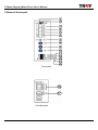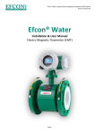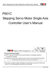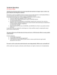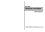
1
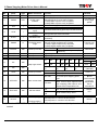
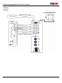
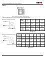
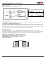
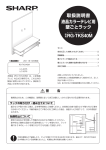
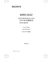
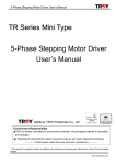
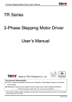
2 Phase Stepping Motor Driver User’s Manual
TR Series
2 Phase Stepping Motor
Driver User ’s Manual
Made by TROY Enterprise Co., Ltd
Anlagentechn ik G mb H
ISO14001
Certificate No.: 09 104 9351
Environment Responsibility
●
TROY is always committed to environment protection. All packaging material is recyclable
●
and reusable.
If disposing of used product, please recycle by type as per waste disposal procedures.
---------------Protect the green earth with your care and commitment---------------
※The product is subject to design modification for performance improvement without prior
notice. For more details please contact your local seller.
TR22PM-OK-V04E
2 Phase Stepping Motor Driver User’s Manual
Precautions
Precautions for using
1.Thank you for purchasing TROY products. Please read this user’s manual thoroughly before
installing and operating the driver, and always keep the manual where it is readily available.
2. The products described in this manual has been designed and manufactured for use in industrial
machinery, and must not be used for any other purpose. We are not responsible for any damage
caused through failure to observe this warning.
3.Check that the motor, driver and any accessories are all present. If an accessory is missing or
damaged, contact the nearest our branches.
4.Never disassemble the motor and driver. Damage or performance impairment may result.
Disassembly voids all warranties.
Precautions for maintenance
Check the ambient environments, clean the system equipment to remove dust and tighten the screws
periodically. Also pay attention to the followings.
1. Contact us when repairs become necessary.
2. Since the temperature of the frame of the driver can rise high, be careful when conducting
maintenance work or inspection work.
Precautions for warranty period
Within the period of one year after delivery of the system equipment, when failures occurring
from design error or fabrication error attributable to the manufacture side occur, we will be
repairing the failure free of charge within the reparable range or will replace with substitute.
(We cannot hold ourselves responsible for breakage and accidents occurring from your use beyond
the specified range described in this document.)
Precautions for disposal
When disposing of the driver and the motor, treat them as ordinary industrial waste.
TR22PM-OK-V04E
2 Phase Stepping Motor Driver User’s Manual
Contents
1.Specs…………………………………………………………… 1
2.Name of driver part……………………………………………2
3.Wiring…………………………………………………………… 4
4.Wiring examples……………………………………………… 6
5.Operation……………………………………………………… 8
6.Installation and dimension………………………………… 9
※For any operational or technical question with the product, please contact us for professional
service「0800-450-168」during our business hours.
TR22PM-OK-V04E
2 Phase Stepping Motor Driver User’s Manual
1.Specs
●Specs
Driver model
Drive current
Input power
Excitation mode
Signal output/input mode
Input signal
CW pulse input
CCW pulse input
H.OFF input
Output signal
TIMING output
TR21PM
0.85A/phase
DC 24V MIN:>1A
1.20A/phase
DC 24V MIN:>1.5A
Bipolar drive
Full step(1.8°),Half step(0.9°);1/4 step(0.45°),1/8 step(0.225°)
●Photo
coupler input
●Open collector output
1pulse: Pulse input;2 pulse:Clockwise pulse input
1 pulse:Rotating direction signal input;2 pulse:Counterclockwise
pulse input
HOLDING OFF input
Excitation phase origin output
Full step:1 signal outputs every 4 pulses
Half step:1 signal output every 8 pulses
1/4 step:1 signal output every 16 pulses
1/8 step:1 signal output every 32 pulses
●Self
test(TEST)
●Pulse
input mode switch(1P/2P)
●Step angle switch【Full,Half(1/2),1/4,1/8】
Functions
●Inner
pulse generate(INT)/External pulse input(EXT)function
selection
Inner pulse : Max pulse speed:5Kpps
Acceleration time ACC:60ms~1.96s
Deceleration time DEC:12ms~1s
●Inverse
Protection modes
LED display
Dimension(mm)
Weight
Temperature
Ambient
power protection:Auto disconnection in the case of
reversed voltage polarities
●Over current protection:Auto disconnection in the case of
current input exceeding rated value
POWER、TIMING
100(L)X65(W)X32(H)
275g
0℃~40℃
Humidity
<85%
Condition
Avoid dust and corrosive、inflammable gas
1
TR22PM-OK-V04E
2 Phase Stepping Motor Driver User’s Manual
2.Name of driver part
Front panel
前端面板
Left
side panel
左側面板
2
TR22PM-OK-V04E
2 Phase Stepping Motor Driver User’s Manual
1.
Name of the
panel
POWER
2.
TIMING
LED
3.
CW
Ι
4.
CCW
Ι
No.
Type
Name of function
LED
Power indicator
Phase origin
indicator
2P:CW pulse input
1P:Pulse input
2P:CCW pulse
input
1P:Run direction
control
5.
H.OFF
Ι
HOLDING OFF
6.
TIMING
O
Excitation phase
origin
7.
EXT/INT
SW
Pulse input mode
8.
9.
10.
SPEED
ACC
DEC
VR
VR
VR
Adjustment
Adjustment
Adjustment
11.
M1
SW
Step angle switch
12.
M2
SW
13.
1P/2P
SW
Pulse input mode
Function
LED lamp lit up when power input
Full step:LED lit up once every 4 pulses
Half step:LED lit up once every 8 pulses
1/4 step:LED lit up once every 16 pulses
1/8 step:LED lit up once every 32 pulses
Clockwise timing pulse input via this terminal
Counterclockwise timing pulse input via this terminal
OFF/ACD
SW
Timing pulse input via this terminal
(L)level input to unexcited the motor.Axle rotated by
hand easily
Full step:1 signal outputs every 4 pulses
Half step:1signal outputs every 8 pulses
1/4 step:1 signal outputs every 16 pulses
1/8 step:1signal outputs every 32 pulses
EXT
Pulse input via CW/CCW
Pulse generated by internal(Tip
INT
switch:1P)
Regulating the motor run speed
Regulating the pulse acceleration time
Regulating the pulse deceleration time
M1
M2
ON
ON
Full step
run
1P side
2P side
M1
M2
M1
M2
M1
M2
OF
OF OF OF
ON ON
F
F
F
F
Half step 1/4 step 1/8 step
run
run
run
1 pulse input
2 pulse input
Motor current to be maintained at
run current upon stopping pulse
input
Auto current down
ACD side
15.
TEST/OFF
SW
Self test switch
16.
MOTOR
O
Motor wiring
Power input (+)
17.
DC 24V
Ι
Power ground(-)
LED will lit up
during high
speed
Counterclockwise timing pulse input via this terminal
OFF side
14.
Remark
Motor current drops approx0.1sec
upon stopping pulse input,so as to
mitigate motor temperature rise
Stop the self test function and set at
OFF side during operation
OFF
side
TEST
Driver rotated CW by 2PPS
side
Connecting the motor to the driver
External power V+ connect to this terminal
External power V- connect to this terminal
Less DC 24V
Less 10mA
Default:INT
Default:50%
Default:50%
Default:0%
Default:
M1
M2
OFF
OFF
1/8 step
(1600 dpi)
Default:1P
Default:
★ACD
recommended
to mitigate
temperature
rise of
motor/driver
Default:
OFF
DC24V
※Indication:LED→LED lamp,SW→Switch,VR→Variable resistor,Ι→Input contact,O→Output
contact
3
TR22PM-OK-V04E
2 Phase Stepping Motor Driver User’s Manual
3.Wiring
3.1Driver
2 phase stepping motor
External power input
DC Power
Control
Interface +5V
CW signal input
CCW signal input
Excitation current
release
Excitation TIMING output
4
TR22PM-OK-V04E
2 Phase Stepping Motor Driver User’s Manual
3.2Motor
Motor connect with driver via this terminal
2 phase stepping motor wiring contrast chart(Variety brands)
●4
leads of internal motor wiring
A phase
Phase
Brand
A
A
B
B
Tamagawa
Blue
Red
White
Yellow
Oriental
motor
Black
Green
Red
Blue
Sanyo
denki
Orange
Blue
Red
Yellow
A phase
B phase B phase
Wiring chart
●6
leads of internal motor wiring
A phase
A phase
B phase
Phase
Brand
A
COM
A
B
COM
B
Tamagawa
Black
Yellow
Green
Red
White
Blue
Oriental
Motor
Black
Yellow
Green
Red
White
Blue
Sanyo
denki
Orange
White
Blue
Red
Black
Yellow
B phase
Do not
connect
Note
Do not
connect
Wiring chart
5
TR22PM-OK-V04E
2 Phase Stepping Motor Driver User’s Manual
4.Wiring examples
4.1External pulse:CW、CCW pulse input
★Note:
Less 20mA
Driver internal circuit
Less 20mA
Controller
output
External power
voltage VO
External resister
R
5V
X
12V
390Ω 1/4W
24V
1KΩ 1/2W
(1)2 pulse input mode
Input pulse has clockwise pulse and counterclockwise pulse; -CW terminal:Clockwise pulse input
-CCW terminal:Counterclockwise pulse input
The negative edge-triggered input is employed. The motor stays at ‘’H’’ level in the case of no pulse
signal output. The motor turns 1 step clockwise in the case of 1 pulse input at CW terminal. The motor
turns 1step counterclockwise in the case of 1 pulse input at CCW terminal.
(2)1 pulse input mode
Input pulse connect to –CW and clockwise/counterclockwise control connect to the –CCW
The negative edge-triggered input is employed. The motor stays at ‘’H’’ level in the case of no pulse
signal output. The pulse signal input to the –CW terminal and –CCW terminal rotation direction
indicates:”H” level clockwise ,”L” level counterclockwise
(3)Pulse voltage range:”H” level is 4~5V,”L” level is 0~0.5V
(4)Pulse width>5μsec and up/down time<2μsec
(5)CW/CCW definition
Motor shaft
CCW(Counterclockwise)
CW(Clockwise)
6
TR22PM-OK-V04E
2 Phase Stepping Motor Driver User’s Manual
4.2Internal pulse:Start/Stop
Less 20mA
Driver internal
circuit
Less 20mA
(1)-CW:STRT/STOP switch at “H” level is STOP(Stop operation condition);at “L” level is
START(Start operation condition)
(2)-CCW:CCW/CW switch at “H” level is clockwise rotation;at “L” level is counterclockwise rotation
Note:
Because of the auto current down(ACD) function,please set the -CCW terminal at “H” level when
motor didn’t run.If motor only need counterclockwise rotation during motor start running.Switching the
motor leads A→B and A→B
★Note:
4.3H.OFF input
Less 20mA
Driver internal
circuit
Controller
output
External power
voltage VO
External
resistor R
5V
12V
X
390Ω 1/4W
24V
1KΩ 1/2W
36V
1.8KΩ 1W
Control signal H.OFF at “L”level and motor excitation release and motor running current declined to
the 0 then motor shaft could be rotated by hand easily
7
TR22PM-OK-V04E
2 Phase Stepping Motor Driver User’s Manual
4.4TIMING output
★Note:
Please add proper external
resistor(R) to keep the current of
the circuit below 10mA
Vo
R=
-RS
10mA
TIMING signal:This timing signal indicates that the excitation state of conforms to the initial detect
home position with greater precision by setting the mechanical home position of equipment to coincide
with the excitation home position (step0) of the motor.
The time (TIMING) lamp on the front panel turns on every 4 pulses at full-step (1.8°/step) ;every 8
pulses at half-step (0.9°/step);every 16 pulses at 1/4 step(0.45°/step)and every 32 pulses at 1/8 step
(0.225°/step).The TIMING lamp is continuously on during high-speed operation, and the transistor is
on.
5.Operation
According to the inquiry and select the stepping mode(Tip switch M1、M2) then switch the tip switch
ACD to the ACD
M1
M2
M1
M2
M1
M2
M1
M2
ON
ON
OFF
ON
ON
OFF
OFF
ON
Running by full
Running by half step
Running by 1/4 step
Running by 1/8 step
step(1.8°/step)
(0.9°/step)
(0.45°/step)
(0.225°/step)
5.1CW、CCW input via external of TR21PM
(1)Switching the toggle switch to the EXT
(2)Selecting the tip switch according to the pulse generator mode(1P or 2P):1P/2P
Select 1P:PULSE connect to the CW terminal,DIR connect to the CCW terminal
(Clockwise/counterclockwise rotation control)
Select 2P:Clockwise PULSE connect to the CW terminal,counterclockwise PULSE connect to the
CCW terminal
5.2Pulse generated from internal of TR21PM
(1)Switching the toggle switch to the INT
(2)Tip switch:1P/2P,please switch to the 1P
(3)-CW:STRT/STOP switch at “H” level is STOP(Stop operation condition);at “L” level is
START(Start operation condition)
-CCW:CCW/CW switch at “H” level is clockwise rotation;at “L” level is counterclockwise rotation
8
TR22PM-OK-V04E
2 Phase Stepping Motor Driver User’s Manual
Note:
Because of the auto current down(ACD) function,please set the -CCW terminal at “H” level when
motor didn’t run.If motor only need counterclockwise rotation while motor start running.Switching the
motor leads A→B and A→B
(5)According to the inquiry and regulate the variable resistor:Pulse speed(SPEED)
Acceleration(ACC)、deceleration(DEC)
5.3TEST(Self-test for drive part)
(1)Switching the toggle switch to the INT
(2)Do not input any signal to the terminal CW and CCW
(3)Tip switch TEST switch to the TEST
(4)Checking the accuracy of TIMING lamp lit up(Please refer to the TIMING output P.11)
5.4Measuring via motor phase current
(1)Turn off the driver power and switch the tip switch ACD to the OFF、TEST to the OFF
(2)First connect the driver to the ammeter then connect to the motor contact A
(3)Turn on the driver power and do not output the pulse to the motor(Motor at standstill without
running);the value of ammeter indicated is phase current
(4)Switching the tip switch ACD to the ACD and the value of ammeter indicated is the phase
current(Holding current) during auto current down condition with motor at standstill without running
current drop rate is approx 60%
6.Installation and dimension
●Driver
dimension
Screws hole
Driver dimension
Mounting bracket dimension
9
TR22PM-OK-V04E
2 Phase Stepping Motor Driver User’s Manual
●Driver
installation
1.Horizontal installation
Mounting
plate
Mounting
plate
<Step 1>
<Step 2>
Locking the installation seat onto the
mounting plate by using 2 screws
Fit the driver into the groove of mounting
plate. Mounted with 2 screws
2.Vertical installation
Mounting
plate
<Step 1>
<Step 2>
Lock the mounting base onto the
mounting plate by using 4 screws
Remove the middle 2 screws of driver.
Vertically fit the driver into the groove of
the mounting base. Then re-mount the
2 removed screws
10
TR22PM-OK-V04E
2 Phase Stepping Motor Driver User’s Manual
*For environment protection, paper saving and resources preservation, please download the user’s
manual directly from SUNHOLY website:http:// www.sunholy.com.tw
Our constant aim:Demand for professionalism
Our belief:
Commitment to every detail
Our innovation: Introduction of cutting-edge equipments
Our pride:
Pursuit of superior products
We are confident that each SUNHOLY products bears tests
For we are highly motivated!
Complete SUNHOLY service system
We offer our customers a complete service package:
♁『0800-450-168 technical hotline service』
♁『Periodical motor E-newspaper』
♁『Motor selection and calculation service』
♁『Professional on site service』
♁『On-site motor technical seminar service』
♁『Total motor solution& after sales service』
Ready for request!.
SUNHOLY TRADING CO., LTD
Professional agency
3F,No78.,Sec2,Chang An E.RD. Taipei, Taiwan.
TEL:+886-2-2516-6060
FAX:+886-2-2508-0323
http://www.sunholy.com.tw
E-mail:[email protected]
TR22PM-OK-V04E