1
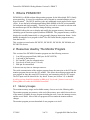
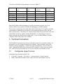
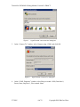
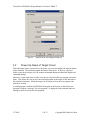
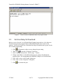
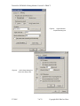
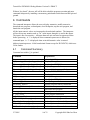
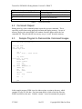
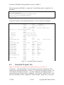
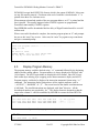
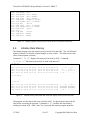
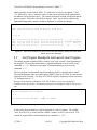
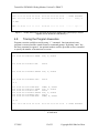
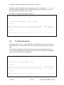
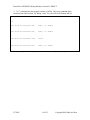
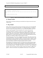
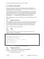
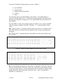
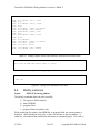
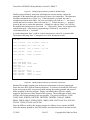
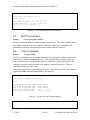
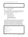
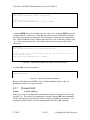
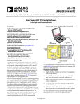
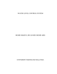
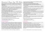
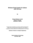
Tutorial
for
PICMON18
Debug Monitor
Version 2.6
DRAFT
Shu-Jen Chen
5/26/2004
Copyright 2004 Shu-Jen Chen
Tutorial for PICMON18 Debug Monitor Version 2.6 DRAFT
1. What is PICMON18?
PICMON18 is a ROM resident debug monitor program for the Microchip® PIC18 family
microcontrollers. It is used in conjunction with a terminal or terminal emulator such as
HyperTerminal®. The RS232 interface is the only additional circuit needed for the target
circuit. It uses the built- in Background Debug Mode (BDM) of the PIC microcontroller
for breakpoint and single stepping. Therefore, the user code is executed in real-time with
the maximum speed of the controller during the debug execution.
PICMON18 allows the user to display and modify the program memory, data memory,
(including special function registers) and data EEPROM. The program memory could be
displayed or modified numerically or using assembly language instruction format. It also
handles download of user program in Intel® Hex file format into the program memory
from the host PC.
This version was tested on the PIC18F252, PIC18F452, PIC18F458, PIC18F8680, and
PIC18F8720 devices.
2. Resources Used by The Monitor Program
This version of the PICMON18 monitor program uses the following resources:
1.
2.
3.
4.
5.
Last 8K byte program Flash (10K bytes for PIC18F8720)
Last bank of data memory
RC6 and RC7 pins for communication
Four levels of stack (out of 31 levels)
RB6 pin for external halt
It does not use any timer or interrupt resources.
The serial communication of the monitor program shares the same pins as the SCI but the
monitor program does not use the SCI module. This allows the monitor program and the
user program to share the same RS232 transceiver and connecting cable for SCI output.
The SCI input could be shared if the “key break” feature (see Section 3.5) is disabled.
A pull-up resistor should be installed on RB6 pin if “key break” feature is not used, a
floating RB6 will render the PICMON18 unusable.
2.1 Memory Usages
The monitor memory usages and available memory for user are in the following table.
The monitor program uses memory at the end of the memory space which leaves the rest
of the memory available for user program including the reset vector, the interrupt vectors,
and the access RAM. Most of the user programs will run under the monitor without
changes.
The monitor program prevents download of user program over itself.
2/7/2005
2 of 32
Copyright 2004 Shu-Jen Chen
Tutorial for PICMON18 Debug Monitor Version 2.6 DRAFT
Device
Program memory
used
Data memory
used
Program memory
available
Data memory
available
PIC18F252
0x6000-0x7FFF
0x500-0x5FF
0x0000-0x5FFF
0x000-0x4FF
PIC18F452
0x6000-0x7FFF
0x500-0x5FF
0x0000-0x5FFF
0x000-0x4FF
PIC18F458
0x6000-0x7FFF
0x500-0x5FF
0x0000-0x5FFF
0x000-0x4FF
0xC00-0xCFF
0x0000-0xDFFF
0x000-0xBFF
0xE00-0xEFF
0x00000-0x1D7FF
0x000-0xDFF
PIC18F8680 0xE000-0xFFFF
PIC18F8720 0x1D800-0x1FFFF
Table 1:
Memory usages of PICMON18
Since the last bank of the data memory is used by the monitor program, use of last
memory bank in user program will hinder the debugging by monitor program.
When code is written using relocatable object files or Microchip C18 compiler, the linker
script should be modified to prevent the use of the monitor program memory and last
bank of data memory. Microchip C18 compiler default linker scripts puts stack at the end
of the RAM, which is in conflict with the PICMON18. Use the debugger version of
linker script (the one with file name ending with ‘i’) will avoid the problem. For other
compilers, please refer to their user’s manual.
3. Terminal Connection
The PICMON18 communicates to the user through a terminal or a terminal emulator. In
this tutorial we will use HyperTerminal as the example. HyperTerminal is part of the
Windows software distribution. Connect the target circuit board to a PC by an RS-232
cable. Although PICMON18 does not use the SCI (USART), it shares the pins with the
SCI. If the device has more than one SCI, the one with the lowest number is used.
3.1
Configurate HyperTerminal
Launch the HyperTerminal on the PC by:
1.
2.
Click Start Programs Accessories Communications HyperTerminal
In the Connection Description, enter a name and select an icon then click OK
2/7/2005
3 of 32
Copyright 2004 Shu-Jen Chen
Tutorial for PICMON18 Debug Monitor Version 2.6 DRAFT
Figure 1:
3.
In the “Connect To” window, select Connect using: COM1 and click OK
Figure 2:
4.
HyperTerminal “new connection” dialog box
HyperTerminal “Connect To” dialog box
In the “COM1 Properties” window, select Bits per second: 19200, Data bits: 8,
Parity: None, Stop bits: 1, Flow control: None.
2/7/2005
4 of 32
Copyright 2004 Shu-Jen Chen
Tutorial for PICMON18 Debug Monitor Version 2.6 DRAFT
Figure 3:
3.2
HyperTerminal “Port Settings” dialog box
Power Up Reset of Target Circuit
When the target circuit is powered on, the power- up reset code display the sign-on banner
on the terminal. The monitor program then starts count down. If any key is pressed
before count down reaches zero, the monitor command interpreter starts and displays the
command prompt.
Otherwise, when count down reaches zero, the previously loaded user program execution
starts. This allows the user to leave the monitor program in the target circuit and remove
the terminal connection. When the target circuit is powered on, the user program runs
after three seconds.
A small program is loaded with PICMON18 monitor in the factory so that before user
program is loaded, a message “No user program!” is displayed on the terminal when an
attempt is made to execute the user program.
2/7/2005
5 of 32
Copyright 2004 Shu-Jen Chen
Tutorial for PICMON18 Debug Monitor Version 2.6 DRAFT
Figure 4:
3.3
Power on reset of PICMON18 without user program loaded
Set Line Delay for Download
Before we move forward, we will finish HyperTerminal setup and save it for future use.
Download program into program Flash or data EEPROM takes time to burn in the
memory. At the end of each line of download, the HyperTerminal needs to pause for the
PIC to finish programming.
1. Click
to disconnect so that you may change the port setting
2. Then click
to open the “Properties” dialog box
3. Select “Setting” tab and click “ASCII setup…” button
4. Change “Line Delay” to 40 milliseconds if you are going to download only
program Flash. For downloading data EEPROM, change it to 80 milliseconds
5. Click “OK” to close “ASCII setup” dialog box
6. Click “OK” to close “Properties” dialog box
7. Click
2/7/2005
to reconnect the port
6 of 32
Copyright 2004 Shu-Jen Chen
Tutorial for PICMON18 Debug Monitor Version 2.6 DRAFT
Figure 5:
HyperTerminal
Properties dialog box
Figure 6:
2/7/2005
ASCII Setup dialog box
where line delay is set
7 of 32
Copyright 2004 Shu-Jen Chen
Tutorial for PICMON18 Debug Monitor Version 2.6 DRAFT
3.4
Save HyperTerminal Settings
At this time, it will be a good time to save the HyperTerminal setting as an icon on the
desktop so that next time you do not have to setup the HyperTerminal.
Click File Save As… and save the setting on the desktop.
An icon like
will appear on the desktop. Next time, just double click the icon
and a HyperTerminal window with the same setting will appear.
3.5
Key Break
“Key break” is a feature to halt the execution of user program and enter PICMON18
command interpreter. To enable “key break”, a jumper should be installed between RB6
pin and the RX pin (RC7 on most of the PIC18). When the program execution is halted,
the content of WREG, STATUS, and PC registers are displayed on the monitor followed
by the content of the program memory pointed by PC and the disassembly of the
instruction.
Figure 7:
Use key break to enter command interpreter after count down
“Key break” feature allows the user to halt the program execution and is a powerful tool
for debugging. But the feature prevent the user program from using the SCI input
because when any key is hit while the user program is running, the user program is
halted. If SCI input is required for the user program, the “key break” jumper should be
removed and a pull- up resistor is installed on RB6 pin.
2/7/2005
8 of 32
Copyright 2004 Shu-Jen Chen
Tutorial for PICMON18 Debug Monitor Version 2.6 DRAFT
Without “key break”, the user still will be able to halt the program execution and enter
command interpreter by installing a momentary push-button switch between RB6 pin and
ground.
4. Commands
The command interpreter allows the user to display memories, modify memories,
download user program, set breakpoint, clear breakpoint, step the user program, and
launch the user program.
All the input numeric values are interpreted as hexadecimal numbers. The interpreter
will not accept any notation such as “0x” in the inputs, though it is used in the output.
The input is not case sensitive. All input characters are converted to uppercase letters
before processing. A ‘!’ is displayed when command syntax error is detected in
command input. A ‘?’ is displayed when an invalid numeric value is entered.
Address input/output uses 16-bit hexadecimal format except for PIC18F8720, which uses
24-bit format.
4.1
Command Summary
Command text within [ ] is optional
Command
Explanation
H
D[F] starting_address [ending_address]
DE starting_address [ending_address]
DP starting_address [ending_address]
DI starting_address [ending_address]
DR
DS
M[F] starting_address
ME starting_address
MP starting_address
MI starting_address
F starting_address end_address value
L
S new_program_counter
T [step_count]
G [starting_addr]
B[P] address [number_of_pass]
BR addr [number_of_pass]
BW addr [number_of_pass]
BMR addr data [number_of_pass]
prints a brief Help screen
Display File registers
Display data EEPROM
Display Program flash
Disassemble the program flash
Display WREG, STATUS and PC
Display stack
Modify File registers
Modify data EEPROM
Modify Program flash
Modify program flash by Instruction
Fill data memory
Download user program
Set program counter
Trace program instructions
Go – launch user program
Set breakpoint at program address
Set breakpoint at data read address
Set breakpoint at data write address
Set breakpoint of data read data match
2/7/2005
9 of 32
Copyright 2004 Shu-Jen Chen
Tutorial for PICMON18 Debug Monitor Version 2.6 DRAFT
BMW addr data [number_of_pass]
BC
P [until_address]
R
<enter>
Table 2:
Set breakpoint of data write data match
Clear breakpoint
Continue program execution until address
Execute reset instruction
Repeat the previous command
Command summary
4.2 Command Repeat
Hitting enter key at the command prompt repeats the previous command. This is
especially useful when tracing program execution and display memory. In case of
memory display, the repeat display will continue from the address where the last
command left. This provides the user an easy way to “scroll” down the memory.
4.3
Sample Program to Demonstrate Command Usages
list
p=18f452
#include <p18f452.inc>
array equ 0x40
sum
equ 0x30
counter equ 0x32
org 0
goto start ; reset vector
org 0x100
start lfsr 0, array
movlw 0x10
movwf counter
clrf sum
clrf sum+1
loop movf POSTINC0, W
addwf sum
bnc
$+4
incf sum+1
decfsz
counter
goto loop
bra
$
end
Figure 8:
Sample program to calculate the sum of an array located at 0x40-0x4F
In this sample program, FSR0 is used as index register to point to the array, which
contains 16 bytes of 8-bit data. Post- increment mode is used to fetch the data into
WREG and add it to the sum. Variable “counter” is used to terminate the program.
2/7/2005
10 of 32
Copyright 2004 Shu-Jen Chen
Tutorial for PICMON18 Debug Monitor Version 2.6 DRAFT
Enter the program in MPLAB as “sample.asm” and build the product “sample.hex” for
download.
:020000040000FA
:0400000080EF00F09D
:1001000000EE40F0100E326E306A316AEE5030264A
:0C01100001E3312A322E86EF00F0FFD709
:00000001FF
Figure 9:
Content of sample.hex
A listing file, sample.lst, is also generated by MPLAB. This file is essential for debugging.
Version 1.4
00000040
00000030
00000032
000000
000000 EF80
000100
000100
000104
000106
000108
00010A
00010C
00010E
000110
000112
000114
000116
EE00
0E10
6E32
6A30
6A31
50EE
2630
E301
2A31
2E32
EF86
00011A D7FF
00001
list
p=18f452
00002
#include <p18f452.inc>
00001
LIST
00002 ; P18F452.INC Standard Header File,
Microchip Technology, Inc.
00845
LIST
00003
00004 array equ 0x40
00005 sum
equ 0x30
00006 counter equ 0x32
00007
00008
org 0
F000
00009
goto
start
; reset vector
00010
00011
org 0x100
F040
00012 start
lfsr
0, array
00013
movlw
0x10
00014
movwf
counter
00015
clrf
sum
00016
clrf
sum+1
00017 loop
movf
POSTINC0, W
00018
addwf
sum
00019
bnc
$+4
00020
incf
sum+1
00021
decfsz counter
F000
00022
goto
loop
00023
00024
bra
$
00025
00026
end
Figure 10:
4.4
The program listing in sample.lst
Download Program File
Make sure line delay is set properly for terminal emulator (see section 3.3).
Command “L” starts downloading. First, the monitor requests the confirmation of the
erasure of the user program memory. Answer “Y” erases the user program memory. For
each 1 Kbyte of memory erased, one “.” is printed. When the user program memory is
erased, the message “Ready to load” is displayed. Click Transfer Send Text File… and
browse to the directory where “sample.hex” resides and enter “sample.hex” as file name.
2/7/2005
11 of 32
Copyright 2004 Shu-Jen Chen
Tutorial for PICMON18 Debug Monitor Version 2.6 DRAFT
PICMON18 accepts Intel HEX32 file format, which is the output of MPLAB. It does not
use any file transfer protocol. Checksum at the end of each line is checked and a “C” is
printed when there is a checksum error.
When attempt to download outside of the user program address, an “E” is printed and the
line is ignored. This usually happened when CONFIG registers are programmed.
Download cannot modify CONFIG registers.
Data EEPROM could be downloaded but line delay of HyperTerminal needs be set at 80
milliseconds.
When a successful download is complete, the monitor program prints an “S” and prompts
the user to hit “enter” key to reset. After reset, hit “enter” key again to stop count down
and get a command prompt.
> L
Erase user program? (Y/N) Y........................
Ready to load
....S
Hit enter to reset
PICMON 18F452 v2.6 (c) 2004, Shujen Chen
Hit any key to enter monitor: 2.1.
>
Figure 11:
4.5
Download program HEX file and reset after download is complete
Display Program Memory
The program memory could be checked using “DP” command followed by the beginning
address and the ending address. Program memory is always displayed in full lines with
16-bit format. The ASCII equivalents are displayed in 8-bit format. Since PIC18 uses
little endian byte ordering, byte swapping occurs between numeric display and ASCII.
Program memory could also be displayed in instruction mnemonic format using “DI”
command. The instruction display format shows all the implicit attributes such as
“, ACCESS”, “, BANKED”, or “, F”. The second word of the double word instructions
is left blank. The invalid instructions are displayed with “data” directive. All the
hexadecimal numbers are preceded by “0x”. The display format is designed so that the
output after column 11 could be assembled by MPLAB to recreate the same HEX file.
> DP 100 120
0100: EE00 F040 0E10 6E32
0110: E301 2A31 2E32 EF86
0120: FFFF FFFF FFFF FFFF
6A30 6A31 50EE 2630
F000 D7FF FFFF FFFF
FFFF FFFF FFFF FFFF
[email protected] 0j1j.P0&
..1*2... ........
........ ........
>
Figure 12:
Display program memory from 0x100 to 0x120
> DI 100
0100: EE00 LFSR
2/7/2005
0, 0x040
12 of 32
Copyright 2004 Shu-Jen Chen
Tutorial for PICMON18 Debug Monitor Version 2.6 DRAFT
0102:
0104:
0106:
0108:
010A:
010C:
010E:
0110:
0112:
0114:
0116:
0118:
011A:
011C:
011E:
F040
0E10
6E32
6A30
6A31
50EE
2630
E301
2A31
2E32
EF86
F000
D7FF
FFFF
FFFF
MOVLW
MOVWF
CLRF
CLRF
MOVF
ADDWF
BNC
INCF
DECFSZ
GOTO
BRA
data
data
0x10
0x32, ACCESS
0x30, ACCESS
0x31, ACCESS
0xFEE, W, ACCESS
0x30, F, ACCESS
0x0114
0x31, F, ACCESS
0x32, F, ACCESS
0x010C
0x011A
0xFFFF
0XFFFF
>
Figure 13:
4.6
Display program memory from 0x100 to 0x120 in instruction mnemonics
Initialize Data Memory
The sample program uses data memory array between 0x30 and 0x4F. We will fill up the
memory with 0x55 so that the content changes are more visible. This shall not have any
effect on the program execution.
Command “D 20 5F” displays data memory from 0x20 to 0x5F. Command
“F 30 4F 55” fills memory from 0x30 to 0x4F with data 0x55.
> D 20 5F
0020:
0030:
0040:
0050:
04
20
10
2F
14
00
00
80
08
41
CD
00
02
00
00
44
11
14
24
00
88
06
05
C9
44
20
00
00
19
8C
30
01
05
02
44
00
01
58
01
00
80
08
20
00
22
48
2A
20
44
C0
40
0A
A9
88
0B
01
F0
00
00
02
08
96
22
9A
......D.
.A... .
....$..0
/..D....
..."D...
.X.H....
D. *@.."
... ....
08
55
55
00
02
55
55
44
11
55
55
00
88
55
55
C9
44
55
55
00
19
55
55
01
05
55
55
00
01
55
55
00
80
55
55
00
22
55
55
20
44
55
55
0A
A9
55
55
01
F0
55
55
02
08
55
55
9A
......D.
UUUUUUUU
UUUUUUUU
/..D....
..."D...
UUUUUUUU
UUUUUUUU
... ....
> F 30 4F 55
> D 20 5F
0020:
0030:
0040:
0050:
04
55
55
2F
14
55
55
80
>
Figure 14:
Fill data memory 0X30-0X4F with 0x55 and display memory before and after
The program uses the data in the array at 0x40 to 0x4F. So data needs be entered in the
array before executing the program. Command “M 40” modifies the data memory
starting at location 0x40. After “enter” key is pressed, the monitor program prints the
2/7/2005
13 of 32
Copyright 2004 Shu-Jen Chen
Tutorial for PICMON18 Debug Monitor Version 2.6 DRAFT
address and the current content “0040: 55-“ and waits for value to be entered. Value
“12” followed by “space” enters the value 12 into current location (0x40) and advance
the address to next location (0x41). The content of the new location is displayed and the
process repeats. When last value 0x30 is entered, “enter” key is used to return to the
command prompt where memory could be displayed to confirm the changes.
> M 40
0040: 55-12 55-14 55-16 55-18 55-1A 55-1C 55-1E 55-20
0048: 55-22 55-24 55-26 55-28 55-2A 55-2C 55-2E 55-30
> D 20 5F
0020:
0030:
0040:
0050:
04
55
12
2F
14
55
14
80
08
55
16
00
02
55
18
44
11
55
1A
00
88
55
1C
C9
44
55
1E
00
19
55
20
01
05
55
22
00
01
55
24
00
80
55
26
00
22
55
28
20
44
55
2A
0A
A9
55
2C
01
F0
55
2E
02
08
55
30
9A
......D.
UUUUUUUU
.......
/..D....
..."D...
UUUUUUUU
"$&(*,.0
... ....
>
Figure 15:
4.7
Enter even numbers from 0x12 to 0x30 into data memory starting at location 0x40;
display the memory afterward
Set Program Breakpoint and Launch User Program
The sample program initializes FSR0, variable “sum” and “counter” at the beginning of
the program. To check the initialization, a program breakpoint is set at 0x10A using
command “B 10A” then the user program is launched starting at reset vector by
command “G 0”.
The user program execution halts when instruction at 0x10A is fetched and executed.
The monitor program takes over and displays WREG, flags of STATUS, PC and the next
instruction to be executed. The flags of STATUS register is displayed with lowercase for
“0” and uppercase for “1”.
Because of the hardware limitation of the PIC18 devices, only one breakpoint is
available at any given time. Subsequent setting of new breakpoint replaces the current
one.
> B 10A
Program breakpoint set at 0x010A
> G 0
W=10 nOZDC PC=010C:50EE MOVF
0xFEE, W, ACCESS
>
Figure 16:
Set program breakpoint at 0x10A and start program execution at 0
At this point, the data memory could be displayed to verify its content. The variable
“sum” at 0x30-0x31 is cleared and the variable “counter” at 0x32 is set to 0x10. The
content of register FSR0 could be displayed by command “D FE9”.
2/7/2005
14 of 32
Copyright 2004 Shu-Jen Chen
Tutorial for PICMON18 Debug Monitor Version 2.6 DRAFT
> D 30 4F
0030: 00 00 10 55 55 55 55 55
0040: 12 14 16 18 1A 1C 1E 20
55 55 55 55 55 55 55 55
22 24 26 28 2A 2C 2E 30
...UUUUU UUUUUUUU
....... "$&(*,.0
10 40 00 ** ** ** ** **
........ .@......
> D FE9
0FE0: 00 7F 00 ** ** ** ** **
>
Figure 17:
4.8
Display data memory from 0x30 to 0x4F then display FSR0; note display of indirect
registers are not allowed and indicated by “**”
Tracing the Program Execution
Program execution could be traced by using “T” command. One instruction in user
program is executed and the control returns to command prompt. By hitting “enter” key,
the trace command is repeated. An optional number could be provided to trace command
to specify the number of instructions to execute.
> T
W=12 nozDc PC=010E:2630 ADDWF
0x30, F, ACCESS
>
W=12 nozdc PC=0110:E301 BNC
0x0114
>
W=12 nozdc PC=0114:2E32 DECFSZ 0x32, F, ACCESS
>
W=12 nozdc PC=0116:EF86 GOTO
0x010C
> T 6
W=12
W=14
W=14
W=14
W=14
W=14
nozdc
nozdc
nozdc
nozdc
nozdc
nozdc
PC=010C:50EE
PC=010E:2630
PC=0110:E301
PC=0114:2E32
PC=0116:EF86
PC=010C:50EE
MOVF
ADDWF
BNC
DECFSZ
GOTO
MOVF
0xFEE, W, ACCESS
0x30, F, ACCESS
0x0114
0x32, F, ACCESS
0x010C
0xFEE, W, ACCESS
> d 30
0030: 26 00 0E 55 55 55 55 55
55 55 55 55 55 55 55 55
&..UUUUU UUUUUUUU
>
Figure 18:
2/7/2005
Use of trace command to single step program execution or execute specified number
of instructions
15 of 32
Copyright 2004 Shu-Jen Chen
Tutorial for PICMON18 Debug Monitor Version 2.6 DRAFT
Breakpoint could be specified with an optional pass count. Command “B 116 4” set a
program breakpoint at address 0x116 and the program execution halts after the fourth
time instruction at location 0x116 is executed.
Command “G” resumes user program execution.
> B 116 4
Program breakpoint set at 0x0116 on pass 0x04
> G
W=1C NOzDc PC=010C:50EE MOVF
0xFEE, W, ACCESS
> D 30 4F
0030: 8A 00 0A 55 55 55 55 55
0040: 12 14 16 18 1A 1C 1E 20
55 55 55 55 55 55 55 55
22 24 26 28 2A 2C 2E 30
...UUUUU UUUUUUUU
....... "$&(*,.0
1C 46 00 ** ** ** ** **
........ .F......
> D FE9
0FE0: 00 7F 00 ** ** ** ** **
>
Figure 19:
4.9
Setting program breakpoint after multiple pass
Set Data Breakpoint
Breakpoint could be set for a read of data from a specified location, a write of data to a
specified location or when the data read/write at a specified location matches a specified
value.
The following example sets a breakpoint when a data write to location 0x31 occurs (a
carry occurs when adding the value from array to location 0x30). When data breakpoint
is hit, the value of the data is also displayed.
> BW 31
Data write breakpoint set at 0x031
> G
W=24 nozdc D=01 PC=0116:EF86 GOTO
0x010C
> D 30 4F
0030: 0E 01 06 55 55 55 55 55
0040: 12 14 16 18 1A 1C 1E 20
55 55 55 55 55 55 55 55
22 24 26 28 2A 2C 2E 30
...UUUUU UUUUUUUU
....... "$&(*,.0
24 4A 00 ** ** ** ** **
........ $J......
> D FE9
0FE0: 00 7F 00 ** ** ** ** **
>
2/7/2005
16 of 32
Copyright 2004 Shu-Jen Chen
Tutorial for PICMON18 Debug Monitor Version 2.6 DRAFT
Figure 20:
Setting data breakpoint when a write to location 0x31 occurs
If we would like to halt the program execution when there are four entries of data left to
be processed, the breakpoint could be set when counter (at location 0x32) is set to 4.
This is accomplished by command “BMW 32 4”.
> BMW 32 4
Data write match breakpoint set at 0x032 with data 0x04
> G
W=28 nozdc D=04 PC=010C:50EE MOVF
0xFEE, W, ACCESS
> D 30 4F
0030: 5C 01 04 55 55 55 55 55
0040: 12 14 16 18 1A 1C 1E 20
55 55 55 55 55 55 55 55
22 24 26 28 2A 2C 2E 30
\..UUUUU UUUUUUUU
....... "$&(*,.0
28 4C 00 ** ** ** ** **
........ (L......
> D FE9
0FE0: 00 7F 00 ** ** ** ** **
>
Figure 21:
4.10
Setting data write match breakpoint at location 0x32 and value 4
Breakpoint Removal and Key Break
Breakpoint is removed by command “BC”.
User program execution could be halted and enter monitor program by user if key break
is enabled. This is useful when user program execution seems to “get lost”. Halting user
program execution and enter monitor program allows examination of register content and
memory.
> BC
Breakpoint removed
> G
[key break here]
W=30 nozdc PC=011A:D7FF BRA
0x011A
> D 30 4F
0030: 10 02 00 55 55 55 55 55
0040: 12 14 16 18 1A 1C 1E 20
55 55 55 55 55 55 55 55
22 24 26 28 2A 2C 2E 30
...UUUUU UUUUUUUU
....... "$&(*,.0
30 50 00 ** ** ** ** **
........ 0P......
> D FE9
0FE0: 00 7F 00 ** ** ** ** **
2/7/2005
17 of 32
Copyright 2004 Shu-Jen Chen
Tutorial for PICMON18 Debug Monitor Version 2.6 DRAFT
>
Figure 22:
4.11
Remove breakpoint, resume program execution then halt it by key break
Modify Program Memory
Modify program memory allows entering a short program for quick testing. It could also
be used for patches by advanced user. Modify program could be done in numeric form or
with instructions.
The following example turns bit 0 of PORTD on and off. You may connect an LED to
RD0 pin to test the result.
000200
000202
000204
000206
9095
8083
9083
EF01 F001
00027
00028
00029
00030
Figure 23:
again
bcf 0xF95, 0
bsf 0xF83, 0
bcf 0xF83, 0
goto again
; TRISD
; PORTD
; PORTD
Sample code for modify program memory
Command “MI 200” starts modifying instructions at location 0x200. It displays the
address, the content of the program memory at that address and the instruction mnemonic
then wait for a new instruction to be entered. “Enter” key advances the address of next
instruction. If a blank line is entered, it will skip to next instruction without making
modification to the current instruction. A “.” terminates the modification and returns to
command prompt.
> MI 200
0200: FFFF data
0xFFFF - BCF F95, 0
0202: FFFF data
0xFFFF - BSF F83, 0
0204: FFFF data
0xFFFF - BCF F83, 0
0206: FFFF data
0xFFFF - GOTO 202
020A: FFFF data
0xFFFF - .
> DI 200 20A
0200:
0202:
0204:
0206:
0208:
020A:
9095
8083
9083
EF01
F001
FFFF
BCF
BSF
BCF
GOTO
data
0xF95, 00, ACCESS
0xF83, 00, ACCESS
0xF83, 00, ACCESS
0x0202
0xFFFF
>
Figure 24:
2/7/2005
Modify program memory by instructions and display the result
18 of 32
Copyright 2004 Shu-Jen Chen
Tutorial for PICMON18 Debug Monitor Version 2.6 DRAFT
“S 200” command sets the program counter to 0x200. The trace command starts
execution from that location. By hitting “enter” key, the LED will flash on and off.
> S 200
> T
W=D0 NozDC PC=0202:8083 BSF
0xF83, 00, ACCESS
>
W=D0 NozDC PC=0204:9083 BCF
0xF83, 00, ACCESS
>
W=D0 NozDC PC=0206:EF01 GOTO
0x0202
>
W=D0 NozDC PC=0202:8083 BSF
0xF83, 00, ACCESS
>
Figure 25:
2/7/2005
Set program counter to 0x200 and single step the program
19 of 32
Copyright 2004 Shu-Jen Chen
Tutorial for PICMON18 Debug Monitor Version 2.6 DRAFT
USER’S MANUAL
5. Start up codes
5.1 Cold start
The monitor code enters cold start with one of the following conditions:
1.
2.
3.
4.
Power on reset
Brown out reset
Execution of reset instruction
Depressing reset button
The cold start displays sign-on banner, and counts down for three seconds. If any key is
hit on the keyboard before countdown reaches to zero, the monitor command interpreter
starts. Otherwise, the user program at location 0 is launched.
5.2 Warm start
The monitor code enters warm start with one of the following conditions:
1.
2.
3.
4.
5.
Breakpoint condition met
Hit any key on the keyboard when “key break” (see Section 7) feature is enabled
Assert RB6 (active low) while executing user program
Single stepping
Stack overflow or underflow
The warm start code prints out the content of WREG, STATUS, PC (which points to next
instruction), the content of the program memory pointed by the PC and the mnemonic of
next instruction. It proceeds to the command interpreter and waits for user input, except
in the case of single stepping.
While single stepping (Trace command), the step count is decremented and the next user
program instruction is executed before returning to warm start again. When the step
count reaches zero, the execution transfers to the command interpreter.
5.3 Stack underflow or overflow
When stack underflow occurs, the stack pointer is reset and the PC is pushed on to the
stack. The monitor will print out the PC (which points to next instruction).
When stack overflow occurs, the stack is unwound and dumped on the output to provide
the sequence that led to the overflow.
> g 100
Stack underflow!
W=00 noZdc PC=0104:0006 POP
2/7/2005
20 of 32
Copyright 2004 Shu-Jen Chen
Tutorial for PICMON18 Debug Monitor Version 2.6 DRAFT
>
Figure 26:
Output of running a test program to cause stack underflow
> g 200
Stack overflow! Unwind the stack:
023C 023A 0238 0236 0234 0232 0230 022E 022C 022A 0228 0226 0224 0222 0220
021E
W=90 noZdc PC=023C:0005 PUSH
>
Figure 27:
Output of running a test program to cause stack overflow
6. Reset button
Depressing the reset button on the target circuit board resets the processor and executes
cold start code.
7. Key break
Often a defect in the user program causes the execution of code to stay in an unintended
loop and is not responding to external stimuli. For debugging purposes, it is helpful to
know the location of the program infinite loop. Key break uses the BDM external halt
feature to stop the program execution and preserve the context of the processor.
The BDM external halt is initiated by a high to low transition of RB6 pin of the
microcontroller. The user may install a jumper between RB6 and RC7 (the RS232 RX
signal) to enable the key break feature. The RS232 data signal normally idles at logic
high. When a key is stroke on the keyboard, the start bit of the data transmission causes
the high to low transition of RB6 to halt the program execution.
The monitor program waits for the completion of the reception of the character from the
keyboard and discard it. The content of WREG, STATUS, PC, and the mnemonic of the
next instruction are displayed before entering the command interpreter. The user will be
able to determine the location of the code execution at the time of keystroke. The user
may use the monitor commands to debug the program after the key break.
The installation of the jumper prevents the user program from using the keyboard input.
If keyboard inputs are desirable by the user program, a momentary pushbutton switch
with a pull- up resistor connected to RB6 pin could be used to break the user program and
enter the monitor program. The BDM external halt is only effective when executing user
program. Once the execution enters the monitor program, the transitions of RB6 pin are
ignored. Therefore, the duration of the pushbutton switch closure is inconsequential.
2/7/2005
21 of 32
Copyright 2004 Shu-Jen Chen
Tutorial for PICMON18 Debug Monitor Version 2.6 DRAFT
8. Command interpreter
The command interpreter allows the user to display memories, modify memories,
download user program, set breakpoint, clear breakpoint, single (or multiple) step the
user program, and launch the user program.
All the input numeric values are interpreted as hexadecimal numbers. The interpreter
will not accept any notation such as “0x” in the inputs, though it is used in the output.
The input is not case sensitive. All input characters are converted to uppercase letters
before processing. A ‘!’ is displayed when command syntax error is detected in
command input. A ‘?’ is displayed when an invalid numeric value is entered.
Address input/output uses 16-bit hexadecimal format except PIC18F8720 which uses 24bit format.
8.1
Repeat command
When the enter key is pressed without entering a command at the command prompt, the
last command entered is repeated. This is a convenient feature for a command like
“Trace”, where each “Enter” keystroke executes one user program instruction. The
repeat feature does not work after entering the assembly code by “MI” command.
After a cold start, the default command is Help.
8.2
Help
Syntax:
H
A brief help screen is printed. The help screen is intended to provide hints of the
command and in no way comprehensive.
> h
D[F,E,P,I] addr [addr] - display mem
D[R,S] - display regs, stack
M[F,E,P,I] addr - modify memory
F addr addr data - fill file regs
B[P,R,W,D,C] addr [count] - set/clear breakpoint
L - load user prog
G [addr] - launch user prog
T [count] - trace prog
P [addr] - proceed until
>
Figure 28:
8.3
Output of the help command
Display memories
Syntax:
D[F E P I R S] starting_address [ending_address]
The Display command displays one of the memories:
F – file registers, RAM (default)
2/7/2005
22 of 32
Copyright 2004 Shu-Jen Chen
Tutorial for PICMON18 Debug Monitor Version 2.6 DRAFT
E – data EEPROM
P – program Flash
I – program Flash in disassembly
R – registers
S – stack
If no selection is given, the default display is file register. If no ending address is
provided, a default length is used. To simplify the monitor program, the display starts
and ends at the boundary of a display line. For example, DF will start and end on a 16byte boundary.
Since the FSRs are used by the monitor program, the indirect access registers do NOT
reflect the memory pointed by the FSRs. Therefore, “**” is printed in place of their
values.
DR, “Display registers”, command essentially print out the line as if a breakpoint is hit.
This allows the user to find out where the program counter is before proceeding with
debugging.
DS, “Display stack”, command dump the return addresses on the stack with the top-ofthe-stack first.
> df 500 548
0500:
0510:
0520:
0530:
0540:
01
04
05
05
00
9E
00
48
00
00
B6
00
05
00
00
04
04
00
00
00
00
00
00
00
00
00
03
00
37
00
00
0A
00
20
00
00
0A
37
00
00
00
A1
00
29
00
00
A1
29
05
00
00
36
05
05
00
00
EF
05
FF
00
00
03
FF
20
00
B6
44
20
05
20
01
46
05
48
6E
01
00
48
00
6F
........
........
.H.....7
.....7 .
........
........
..6..DF.
.)... .H
)... .H.
..... no
>
Figure 29:
Display file register (RAM) from location 0x500 to 0x548
> dp 1064 10a4
1060:
1070:
1080:
1090:
10A0:
CFFD
0A0D
0000
6F6C
6EF7
F501
7453
0A0D
0077
0E70
CFFE
6361
7453
0E80
6EF6
F500
206B
6361
1710
D007
9CD4
766F
206B
AEFC
ACFC
ECC9
7265
6E75
D006
D009
F00E
6C66
6564
9EFC
9CFC
D012
776F
6672
0E10
0E10
........
..Stack
....Stac
low.....
.np..n..
........
overflow
k underf
........
........
>
Figure 30:
Display program memory from location 0x1064 to 0x10A4
DI command displays instructions in a format that is compatible to MPASM. When the
first two column (address and numeric values) are removed, the output should assemble
to the same memory image. Code not understood by the DI command is displayed with
pseudo- instruction “data” followed by its numeric value. “data” is recognized by
MPASM as a valid directive.
2/7/2005
23 of 32
Copyright 2004 Shu-Jen Chen
Tutorial for PICMON18 Debug Monitor Version 2.6 DRAFT
> di 54c
054C:
054E:
0550:
0552:
0554:
0556:
0558:
055A:
055C:
055E:
0560:
0562:
0564:
0566:
0568:
056A:
C017
F01C
C018
F01B
50F5
021C
CFF4
F017
CFF3
F018
0009
50F5
0123
0156
0342
021C
MOVFF
0x017, 0x01C
MOVFF
0x018, 0x01B
MOVF
MULWF
MOVFF
0xFF5, W, ACCESS
0x1C, ACCESS
0xFF4, 0x017
MOVFF
0xFF3, 0x018
TBLRD*+
MOVF
0xFF5, W, ACCESS
data 0x0123
data 0x0156
MULWF 0x42, BANKED
MULWF 0x1C, ACCESS
>
Figure 31:
Display program memory with instruction mnemonics from location 0x50
> dr
W=A4 noZdC PC=0BAE:2EE8 DECFSZ 0xFE8, F, ACCESS
>
Figure 32:
Display registers and next instructions
Figure 33:
Display return addresses on the stack
> ds
0910 0066
>
8.4
Modify memories
Syntax:
M[F,E,P,I] starting_address
The Modify command allows the user to modify:
F – file registers, RAM (default)
E – data EEPROM
P – program Flash
I – program Flash in assembly code
While modifying file register, data EEPROM, or program Flash, the current content is
displayed. After entering the new value, a space will advance to the next address. A
return key will terminate the modification and return to command prompt. If no value is
2/7/2005
24 of 32
Copyright 2004 Shu-Jen Chen
Tutorial for PICMON18 Debug Monitor Version 2.6 DRAFT
given, the current value is not modified but will advance to the next address. If an invalid
character is typed for a value, a ‘?’ is displayed followed by a new line to repeat the same
location. The range of the value is not checked. Out of range value is truncated.
> df 210
0210: 86 04 25 21 40 08 90 6A
40 49 00 2C 56 90 40 0E
..%[email protected] @I.,V.@.
> mf 210
0210: 86-11 04-22 25-33 21-44 40-55
> df 210
0210: 11 22 33 44 55 08 90 6A
40 49 00 2C 56 90 40 0E
."3DU..j @I.,V.@.
>
Figure 34:
Modify five bytes of file register starting at 0x210 and display before and after the
modifications
> mf 217
0217: 6A-55 40-4s
?
0218: 40-66
> df 210
0210: 11 22 33 44 55 08 90 55
66 49 00 2C 56 90 40 0E
."3DU..U fI.,V.@.
>
Figure 35:
> dp 300
0300: FFFF FFFF FFFF FFFF
Modify file register with error in input
FFFF FFFF FFFF FFFF
........ ........
> mp 300
0300: FFFF-1234
?
0306: FFFF-7777
> dp 300
FFFF-5678
0300: 1234 5678 ABCD 7777
FFFF-abcd
FFFF-efgh
FFFF FFFF FFFF FFFF
4.xV..ww ........
>
Figure 36:
Modify program memory with error in input
If an attempt is made to modify program Flash outside of user memory area, a double
“##” is displayed and the modification is aborted.
> mp 7000
7000: FFFF-1234 ##
>
2/7/2005
25 of 32
Copyright 2004 Shu-Jen Chen
Tutorial for PICMON18 Debug Monitor Version 2.6 DRAFT
Figure 37:
Modify program memory outside of allowed region
Modify program Flash by instruction will display the current memory content, the
mnemonic of the instruction and wait for user to enter a new instruction. The instruction
should be terminated by an “Enter” key. If the instruction is accepted, the code is
assembled and stored in the Flash. An error in assembly will result in a ‘!’. An error in
invalid character for numeric value will result in a ‘?’. Follow the error, a ‘-‘ prompt is
given for the user to reenter the instruction. A blank line with an “Enter” key will skip
the modification and advance to next word. A ‘.’ followed by “Enter” key terminates the
modification mode. Flash memory programming is followed by verification. If
verification failed, an ‘x’ is printed.
A pseudo- instruction “data” could be used to enter numeric values for a constant table.
The number following “data” is interpreted as a 16-bit hexadecimal value.
> mi 200
0200: 5002 MOVF
0x02, W, ACCESS - movlw 34
0202: 0F01 ADDLW
0x01 - movff 765, 432
0206: 0606 DECF
0x06, F, ACCESS - call 346
020A: D002 BRA
0x0210 - data 123
020C: 8480 BSF
0xF80, 02, ACCESS - .
> di 200 210
0200:
0202:
0204:
0206:
0208:
020A:
020C:
020E:
0210:
0E34
C765
F432
ECA3
F001
0123
8480
D001
9480
MOVLW
MOVFF
0x34
0x765, 0x432
CALL
0x0346
data
BSF
BRA
BCF
0x0123
0xF80, 02, ACCESS
0x0212
0xF80, 02, ACCESS
>
Figure 38:
Modify program memory by instruction mnemonics
Caveat: This monitor program runs in the same environment as the user program and
shares the same SFRs (Special Function Registers). In order not to disturb the SFRs used
by the user program, they are preserved upon entering the monitor program and restored
before returning to the user program. Display and modify these SFRs are actually
mapped to the preserved values instead of the registers. The modification of these values
will take effect when returning to the user program. The preserved SFRs are: TOSU,
TOSH, TOSL, STKPTR, TBLPTRU, TBLPTRH, TBLPTRL, TABLAT, FSR0H,
FRS0L, FSR1H, FRS1L, FSR2H, FRS2L, WREG, BSR, STATUS, RCSTA, INTCON,
T0CON, T1CON, T2CON, and T3CON.
Since the FSRs are used by the monitor program, the indirect access registers do NOT
reflect the memory pointed by the FSRs and the associated increment or decrement of the
2/7/2005
26 of 32
Copyright 2004 Shu-Jen Chen
Tutorial for PICMON18 Debug Monitor Version 2.6 DRAFT
FSRs does NOT affect the user program’s FSRs. Therefore, “**-” is printed in place of
their values and the modifications are skipped.
8.5
Fill data memory
Syntax:
F starting_address end_address value
Fill command fills the specified RAM region with the specified value.
> f 120 15f 33
> d 100 18f
0100:
0110:
0120:
0130:
0140:
0150:
0160:
0170:
0180:
00
00
33
33
33
33
00
28
00
00
01
33
33
33
33
06
00
42
00
04
33
33
33
33
00
20
04
00
00
33
33
33
33
00
8A
00
03
00
33
33
33
33
00
40
00
01
00
33
33
33
33
00
08
80
00
00
33
33
33
33
00
00
0C
08
00
33
33
33
33
10
04
00
00
02
33
33
33
33
24
00
00
00
10
33
33
33
33
A2
40
00
20
00
33
33
33
33
00
00
00
02
00
33
33
33
33
00
08
01
C0
00
33
33
33
33
01
03
02
80
80
33
33
33
33
10
10
40
42
08
33
33
33
33
00
00
00
40
10
33
33
33
33
86
08
00
........
........
33333333
33333333
33333333
33333333
........
(. .@...
.B......
.. ...B@
........
33333333
33333333
33333333
33333333
$.......
.@......
.....@..
>
Figure 39:
8.6
Syntax:
Fill data memory (RAM) from 0x120 to 0x15F with 0x 33 and display the result
Download user program
L
When the download command is executed, the monitor prompts the user to confirm
before erasing the user program area of the program memory. A “Y” answer will
proceed to erase the program Flash. An “N” will skip the erasure. Any other answers
will abort the operation and return to command prompt. After memory is erased, the
monitor prompts the user to download the file. The download command accepts Intel
Hex file format. The file is buffered one line at a time. After the whole line is received,
the line is then loaded into the program Flash or data EEPROM. Since no flow control is
implemented, a 40 ms line delay is required at the HyperTerminal for downloading
program FLASH. An 80 ms line delay is required when downloading data EEPROM.
A successful line received is echoed with a ‘.’; a failure in the line received is echoed by
an ‘C’. An attempt to download location outside of user program or data EEPROM area
will be ignored and echoed with an ‘E’. At the end of a successful download, an ‘S’ is
echoed and a prompt message is displayed asking user to confirm the forced cold start. If
error(s) occurred during download, an ‘F’ is displayed. Flash memory programming is
followed by verification. If verification failed, an ‘x’ is printed.
> l
Erase user program memory? (Y/N) y....
Ready to load
...C..E..F
File download complete, hit enter to reset
Figure 40:
2/7/2005
A failed download with transmission error and out of range error
27 of 32
Copyright 2004 Shu-Jen Chen
Tutorial for PICMON18 Debug Monitor Version 2.6 DRAFT
> l
Erase user program memory? (Y/N) y....
Ready to load
........................................S
File download complete, hit enter to reset
PICMON 18F452 v2.5.1 (c) 2004, Shujen Chen
Hit any key to enter monitor: 4.3.
>
Figure 41:
8.7
A successful download with forced reset
Set PC command
Syntax:
S new_program_counter
Set PC command modifies the saved program counter value. This value is pushed on the
stack before returning to the user program. Therefore, when Trace command or Go
command is issued, the user program execution starts at the new location.
8.8
Trace command
Syntax:
T [step_count]
The Trace command executes a single instruction in user program, displays registers and
returns to the monitor command interpreter. If an optional numeric count is given, the
Trace command will trace through the number of instructions, print registers after each
instruction execution and then return to the monitor command interpreter. The trace
command default step count is one.
The instruction executed is pointed by the saved PC value. The saved PC value could be
displayed by DR command and modified by S command.
> t
W=30 noZdc PC=0046:ECDC CALL
0x01B8
> t 5
W=30
W=30
W=30
W=30
W=30
noZdc
noZdc
noZdc
noZdc
noZdc
PC=01B8:6E83
PC=01BA:6A80
PC=01BC:6A95
PC=01BE:D000
PC=01C0:8680
MOVWF
CLRF
CLRF
BRA
BSF
0xF83,
0xF80,
0xF95,
0x01C0
0xF80,
ACCESS
ACCESS
ACCESS
03, ACCESS
>
Figure 42:
A single step and a multiple stepping
> s 4a
> t
2/7/2005
28 of 32
Copyright 2004 Shu-Jen Chen
Tutorial for PICMON18 Debug Monitor Version 2.6 DRAFT
W=FF noZdc PC=004C:6F02 MOVWF
0x02, BANKED
>
W=FF noZdc PC=004E:0EB0 MOVLW
0xB0
>
Figure 43:
8.9
Modify program counter to 0x4A and continue single stepping
Launch user program
Syntax:
G [starting_addr]
The G command will launch the user program starting from the saved program counter
value or the optional starting address given at the command line. After a reset or a cold
start, the saved program counter value is set to 0. The saved program counter value could
be displayed by DR command and modified by S command.
8.10
Set/clear breakpoint
Syntax:
B[P] addr [number_of_pass]
BR addr [number_of_pass]
BW addr [number_of_pass]
BMR addr data [number_of_pass]
BMW addr data [number_of_pass]
BC
Command BP sets a program breakpoint address. When the program counter (PC) of the
user program execution matches the breakpoint address, the user program halts and enters
monitor. Some critical registers and the next instruction to be executed are displayed.
An optional number could be provided so that the execution halts after matching the
breakpoint address for the number of passes specified. The pass number is only
applicable for one time use after the breakpoint set command, but the breakpoint will
remain active until cleared by BC command. After a multi-pass breakpoint hit, the
breakpoint remains active but the pass number is set to one. If multi-pass breakpoint is
desired again, the user needs to re-enter the breakpoint command with the pass number.
> di 0 22
0000:
0002:
0004:
0006:
0008:
000A:
000C:
000E:
0010:
0012:
0014:
0016:
0018:
001A:
0000
0100
EE00
F000
EE10
F050
6A00
5000
ECDA
F03E
0E20
ECD2
F03E
CFEE
2/7/2005
NOP
MOVLB
LFSR
0x00
0, 0x000
LFSR
1, 0x050
CLRF
MOVF
CALL
0x00, ACCESS
0x00, W, ACCESS
0x7DB4
MOVLW
CALL
0x20
0x7DA4
MOVFF
0xFEE, 0xFE6
29 of 32
Copyright 2004 Shu-Jen Chen
Tutorial for PICMON18 Debug Monitor Version 2.6 DRAFT
001C: FFE6
001E: 2A00 INCF
0020: D7F6 BRA
0x00, F, ACCESS
0x000E
>
Figure 44:
Display of a sample program (as a demonstration of breakpoint use below). This
program prints out the loop counter (at location 0) and copies a byte from input buffer
(starting at 0) to output buffer (starting at 0x50).
> bp 1e
Program breakpoint set at 0x001E
> g 0
00
W=20 noZdc PC=0020:D7F6 BRA
0x000E
> bp 1e 4
Program breakpoint set at 0x001E on pass 0x04
> g
01 02 03 04
W=20 noZdc PC=0020:D7F6 BRA
0x000E
>
Figure 45:
Set a single pass program breakpoint at 0x1e and a multi-pass breakpoint at the
same program location
Command BR sets a data read breakpoint at a RAM address. When a read from the
breakpoint address occurs, the program execution halts. Command BW works similar as
BR except the program execution halts when a write to the breakpoint address occurs.
The optional pass counter may be applied for BR and BW too. When breakpoint is hit by
data read/write, the value of the data is display with “D=” in the register display line.
> br 15
Data read breakpoint set at 0x015
> g 0
00 01 02 03 04 05 06 07 08 09 0A 0B 0C 0D 0E 0F 10 11 12 13 14 15
W=20 noZdc D=08 PC=001E:2A00 INCF
0x00, F, ACCESS
>
Figure 46:
A data read breakpoint at location 0x15
> bw 62
Data write breakpoint set at 0x062
> g 0
00 01 02 03 04 05 06 07 08 09 0A 0B 0C 0D 0E 0F 10 11 12
W=20 noZdc D=00 PC=0020:D7F6 BRA
0x000E
>
Figure 47:
2/7/2005
A data write breakpoint at location 0x62
30 of 32
Copyright 2004 Shu-Jen Chen
Tutorial for PICMON18 Debug Monitor Version 2.6 DRAFT
> br 0 14
Data read breakpoint set at 0x000 on pass 0x14
> g 0
00 01 02 03 04 05 06 07 08
W=20 noZdc D=08 PC=000E:5000 MOVF
0x00, W, ACCESS
>
Figure 48:
A multi-pass data read breakpoint at location 0
Command BMR sets a pair of address/data for a data read. Command BMW sets a pair
of address/data for a data write. When the data transfer matches both address and data
specified, the program execution halts. The optional pass counter may be applied here
alos. When breakpoint is hit by address/data match, the value of the data is display with
“d=” in the register display line. It should be identical to the value specified in the
breakpoint.
> bmr 0 22
Data read match breakpoint set at 0x000 with data 0x22
> g 0
00 01 02 03 04 05 06 07 08 09 0A 0B 0C 0D 0E 0F 10 11 12 13 14 15 16 17 18 19
1A 1B 1C 1D 1E 1F 20 21
W=22 noZdc D=22 PC=7DB4:EF72 GOTO
0x6EE4
>
Figure 49:
A data match breakpoint at location 0 with data value 22
Command BC clears the breakpoint.
> bc
Breakpoint removed
>
Figure 50:
Removing all types of breakpoint
Because of the limitation of BDM to have a single breakpoint register, only one
breakpoint could be set at any given time.
8.11
Syntax:
Proceed Until
P [until_address]
Often, the user sets a breakpoint then continues the program execution from where the
current PC is. This could be accomplished by issuing command BP then command G.
The P command (proceed until) does both in a single command for convenience. The
breakpoint remains effective after P command until removed by BC command.
2/7/2005
31 of 32
Copyright 2004 Shu-Jen Chen
Tutorial for PICMON18 Debug Monitor Version 2.6 DRAFT
> p 2d2
W=02 nozDC PC=02D4:6E0B MOVWF
0x0B, ACCESS
>
Figure 51:
8.12
Reset
Syntax:
R
Proceed from the current PC until program address 0x02d2
The reset command executes the reset instruction and forces a cold start.
2/7/2005
32 of 32
Copyright 2004 Shu-Jen Chen