1
WATER LEVEL CONTROL SYSTEM
MOHD SHAIFUL IRUAN BIN MOHD ARIS
UNIVERSITI TEKNOLOGI MALAYSIA
PSZ 19:16 (Pind. 1/07)
UNIVERSITI TEKNOLOGI MALAYSIA
DECLARATION OF THESIS / UNDERGRADUATE PROJECT PAPER AND COPYRIGHT
Author’s full name :
MOHD SHAIFUL IRUAN BIN MOHD ARIS
Date of birth
:
12 FEBUARY 1988
Title
:
WATER LEVEL CONTROL SYSTEM
Academic Session:
2010/2011 - 2
I declare that this thesis is classified as :
√
CONFIDENTIAL
(Contains confidential information under the Official Secret
Act 1972)*
RESTRICTED
(Contains restricted information as specified by the
organisation where research was done)*
OPEN ACCESS
I agree that my thesis to be published as online open access
(full text)
I acknowledged that Universiti Teknologi Malaysia reserves the right as follows :
1. The thesis is the property of Universiti Teknologi Malaysia.
2. The Library of Universiti Teknologi Malaysia has the right to make copies for the purpose
of research only.
3. The Library has the right to make copies of the thesis for academic exchange.
Certified by :
SIGNATURE
880212-11-5765
(NEW IC NO. /PASSPORT NO.)
Date : 20 MAY 2011
NOTES :
SIGNATURE OF SUPERVISOR
DR SALINDA HJ BUYAMIN
NAME OF SUPERVISOR
Date : 20 MAY 2011
*If the thesis is CONFIDENTIAL or RESTRICTED, please attach with the letter from
the organisation with period and reasons for confidentiality or restriction.
“I declare that I have read this work and in my opinion this work is adequate
in term of scope and quality for the purpose of awarding a Bachelor of
Engineering (Electrical - Mechatronic)”
Signature
: …………………………………..
Name of Supervisor : Dr Salinda Hj Buyamin
Date
: 20th MAY 2011
i
WATER LEVEL CONTROL SYSTEM
MOHD SHAIFUL IRUAN BIN MOHD ARIS
A thesis is submitted in fulfillment of the requirements for the award of Bachelor of
Engineering (Electrical – Mechatronic)
Faculty of Electrical Engineering
Universiti Teknologi Malaysia
MAY 2011
ii
I declare that this thesis entitled “Water level Control System” is the result of my
own research except as cited in the references. The thesis has not been accepted for
any degree and is not concurrently submitted in candidature of any other degree.
Signature
:…………………………………………………
Name
:MOHD SHAIFUL IRUAN BIN MOHD ARIS
Date
:
iii
Special dedicated to my beloved mother, father, brother, sister and friends for
support, encouragement and motivation through my journey of education.
iv
ACKNOWLEDGEDMENT
I am heartily thankful to my supervisor; Dr Salinda Hj Buyamin, whose
encouragement, guidance and support from the initial to the final level enabled me to
develop an understanding of the subject. She inspired me greatly to work in this
project. Her willingness to motivate me contributed tremendously to the project. I
also would like to thank her for showing me some example that related to the topic of
the project.
Deepest thanks and appreciation to my parents, family, special mate of mine,
and others for their cooperation, encouragement, constructive suggestion and full of
support for the report completion, from the beginning till the end. Also thanks to all
of my friends and everyone, that has been contributed by supporting my work and
helps myself during the final year project progress till it is fully completed.
Lastly, I offer my regards and blessings to all of those who supported me in
any respect during the completion of the project.
v
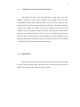
ABSTRACT
The objectives of this project to build a Virtual Water Level Control System
(VWLCS) by using Microsoft Visual Basic and to build the prototype of Automatic
Water Level Control System (AWLCS) that will be able to display the current level
of the water in tower tank and base tank .The water level control system between
base tank and tower tank are always gave the problems to the user. The problem with
the system is there no indicator to show the current level of water in both tanks. The
user does not know the current level of water in their tanks to and not be able to plan
to use that water effectively and alert them if the water supply is stop. The prototypes
AWLCS was developed to reduce the human interface between machines and make
the machine to operate in sequential step. The prototype system for AWLCS is
especially design to sense the water level in both tanks that will give signal to
microcontroller to start or stop the pump. It designed was also to automatically
control the water pump motor which ensures the constants reserve water in based
tank.
vi
ABSTRAK
Objectif projek ini adalah untuk membina sistem kawaln air bayangan
(VWLCS) dengan menggunakan Mikrosoft Visual Basic dan juga untuk membina
model bagi system kawalan air automatic (AWLCS) yang boleh menunjukkan paras
air di dalm tangki rumah iaitu tangki atas dan tangki simpanan bawah. Sistem
kawalan paras air diantara tangki atas dan tangki simpanan selalu mendatangkan
masalah kepada pengguna. Masalh timbul kerana tiada penunjuk untuk menunjukkan
paras air sebenar yang ada didalam kedua-dua tangki. Ini menyebabkan pengguna
tidak dapat merancang penggunaan air dengan berkesan seandainya bekalan air ke
tangki simpanan terputus. Model untuk AWLCS telah dibina khas untuk mengesan
paras air bagi kedua-dua tangki dan akan menghantar isyarat kepada mikropengawal
samada untuk menghidupkan atau mematikan pam air. Model ini telah dibina untuk
mengawal pam air secara automatik bagi mengelakkan kerosakkan terhadap pam air
yang digunakan.
vii
TABLE OF CONTENTS
CHAPTER
1
2
TITLES
PAGE
TITLE PAGE
i
DECLRATION OF THESIS
ii
DEDICATION
iii
ACKNOWLEDGMENT
iv
ABSTRACT
v
ABSTRAK
vi
TABLE OF CONTENT
vii
LIST OF TABLES
x
LIST OF FIGURES
xi
LIST OF APPENDICES
xii
INTRODUCTION
1
1.1
Introduction
1
1.2
Problem Statement
2
1.3
Objectives of Project
3
1.4
Scope of Project
3
1.5
Outline of Thesis
4
LITERATURE REVIEW
5
2.1
Overview
5
2.2
Type of Water Level Control System
6
2.2.1 Traditional Water Level Control System
6
viii
2.3
2.4
2.2.2 Manual Water Level Control System
8
2.2.3 Automatic Water Level Control System
9
Advantages and Disadvantages
11
2.3.1 Traditional Water Level Control System
11
2.3.2 Manual Water Level Control System
12
2.3.3 Automatic Water Level Control System
12
Available Design/Project
13
3
METHODOLOGY
14
3.1
Hardware Implementation
14
3.2
Main Board
14
3.2.1
16
Microcontroller – PIC 18F452
3.2.1.1
Pin Description of the PIC
18F452
3.2.2
LCD 16x2
21
3.3
Water Level Sensor Board
23
3.4
Relays board
24
3.5
Power Supply Board
27
3.6
Software Implementation
27
3.7
Virtual Water Level Control System (VWLCS)
27
3.7.1
Manual Mode
28
3.7.2
Automatic Mode
29
3.8
Automatic Water Level Control System
(AWLCS)
3.9
30
PICkit 2 v2.55 software with USB ICSP
PIC Programmer
4
18
31
RESULTS AND DISCUSSIONS
35
4.1
Result
35
4.2
Discussion
36
ix
4.2.1
4.2.2
5
Testing: PIC 18F452 Pins
36
4.2.1.1
Procedures
37
4.2.1.2
Result and Analysis
38
Experiment: Probe sensor testing
38
4.2.2.1
Procedures
38
4.2.2.2
Result and Analysis
39
4.3
Result and Analysis for VWLCS
39
4.4
Result and Analysis for AWLCS
43
CONCLUSION AND FUTURE WORK
46
5.1
Conclusions
46
5.2
Future Work
47
REFERENCES
48-49
APPENDICES
50-66
x
LIST OF TABLES
TABLE NO.
TITLE
PAGE
2.1
Traditional water level control system operation theory
7
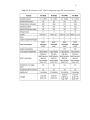
3.1
Key features of PIC 18F452 compared to other PIC
17
microcontroller
4.1
Light of LED
36
4.2
Probe sensor measurement
38
xi
LIST OF FIGURES
FIGURE NO.
TITLE
PAGE
2.1
Block diagram of a traditional water level controller
8
2.2
Block diagram of automatic water level control system
10
3.1
Main board
15
3.2
Pin diagram of PIC 18F452
18
3.3
PIC 18F452 pin connection
21
3.4
Sensor board
22
3.5
Water level sensor schematic diagram
23
3.6
Relay board
24
3.7
SPDT relay circuit diagram
25
3.8
Power Supply Board
26
3.9
Flow chart for manual mode
28
3.10
Flow chart for automatic mode
29
3.11
MikroC Pro Compiler for PIC software
30
3.12
PICkit2 Programmer
32
3.13
PIC kit2 software after successful download hex file
33
3.14
USB ICSP PIC programmer diagram
34
4.1
VWLCS selecting mode
39
4.2
Manual mode for VWLCS
40
4.3
Automatic mode for VWLCS
41
4.4
AWLCS display system
42
4.5
Results for AWLCS (a)
43
4.6
Results for AWLCS (b)
44
4.7
Results for AWLCS (c)
45
xii
LIST OF APPENDICES
APPENDIX
A
TITLE
Source Code for AWLCS
PAGE
50-66
CHAPTER 1
INTRODUCTION
1.1
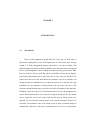
Introduction
Water is really important to people daily life. Every day, we need water to
bath, drink, washing and to work. Occasionally there is a time when water is really
needed. It is really disappointed situation when there is no water available. This
situation happen not because of none availability of the water but due to wastage and
lack of water management control. Nobody care about how they get the water. What
they care is there is water to used. But when no availability of water always happen,
people know that problem will be affect their life. So, they come out with idea of to
control the water level in the tank. Before the automatic water level controller was
designed, people use traditional way to control the water level in the tank. By using
traditional way, the controller is usually placed at the top of the water tower. The
corrosion and mal-function may occur due to the effect of humidity to the controller.
In addition, when the water level of the basement tank is too low, the pumping motor
may be burned because there is no water to be pumped. People also use the manual
way to control the water level in their tank, but this process always needs to be
repeated. To overcome this situation people come with the Automatic Water Level
Controller. The automatic water level control system is using a controller design to
automatically switch on or off motor to maintain water level in the over head tank.
2
The design or project consisted of one control unit and level sensor. The level
sensor continuously monitor the water level and sends the signal to switch on the
motor when the water level in the tank becomes below the low set limit and switch
off the motor when the water level reaches the high level setting. It also switches off
when the pump water is exhausted before filling overhead tank, to avoid the pump
running dry. Although the water level was control automatically, the user still does
not know the actual level of water in their tank water.
Hence, it is really important to improve current automatic water level
controller by improving on the monitoring of the actual level of water. By knowing
the actual level of water, the user can prepare and plan how to use their water based
on the current quantity of water. This will make sure the water can be used in
efficient way and there problem of non-availability will not occur.
1.2
Problem Statement
Although the manual way for controlling the water level between two water
tank is a good to avoid electricity and water wastage, but sometimes can cause nonavailability of water and also wastage if the user fail to follow to the manual
operating in time. The automatic water level control system is a good system that
will continuously monitor the level of water in both tanks which will ensure no
wastage of electricity and water and avoid the dry running. But some improvement is
needed by added water level indicator for the system. This will make sure the water
can be used in efficient way and the problem of non-availability will not occur.
3
1.3
Objectives of Project
The main objective for this project is to display the current levels of water in
the tank especially for a house property which is base tank and tower tank. Another
objective of this project is to control the water pump motor automatically and also to
indicate either the water pump is in operating or not.
1.4
Scopes of Project
In order to achieve the objectives of this project a virtual model for Water
Level Control System (VWLCS) and also a prototype for Automatic Water Level
Control System (AWLCS) are design and build.
VWLCS was designed by using a Microsoft Visual Basic. The virtual model
was designed to be able to operate in two modes which are in manual mode and also
in automatic mode. A prototype for AWLCS was build to operate in automatic mode
only. The levels of water in both tank and the operating for the water pump are
displayed by using LCD and LED as indicator.
4
1.5
Outline of Thesis
There are five chapters in this thesis. In first chapter, it discusses about the
problem statement, objective and scope of this project. Chapter two is discussion
about the literature reviews that have been done. It will cover the study between
traditional control system and digital water level control system, while also covering
subjects such as microcontroller and MikroC Pro Compiler used in programming.
Chapter three consists of discussion on methodology in hardware and
software implementation of this project. The hardware implementation discussed the
circuit that was design. The result and discussion that gathered from the project will
be presented in chapter four. It discussed the result of this project and also the way to
make this project successfully achieve the objective. The last chapter, which is
chapter five, is about conclusion of this project and future work that can be done.
CHAPTER 2
LITERATURE REVIEW
2.1
Overview
Generally most houses and buildings have two water tanks, one placed on the
roof and another one on the ground or sometimes underground. Water is first stored
in an underground tank or called as based tank and from there it is pumped up to the
overhead tank or called as tower tank located on the roof [1, 2]. People who live in
their own house are easily to control the water level in the tank. They generally
switch ON the pump when their taps go dry and switch OFF the pump when the
overhead tank starts overflowing. This results in the unnecessary wastage.
That way was really good management to avoid undue wastage but
sometimes causes non-availability of water in the case of emergency [1, 2]. For the
residents who live in high buildings, they can’t control the water level in the tanks.
The system that was used is either traditional or automatic water level control system
to control the water between two different level tanks [1]. By using the traditional
water level control system it will save a cost [1] and use simple structure. However,
since the controller is usually placed at the top of the water tower, corrosion and malfunction may occur due to the effect of humidity to the controller. Meanwhile, if the
6
water level of the basement tank is too low, the pumping motor may be burned
because there is no water to pump.
People who control their tank water level manually also face a few problems
due to manual process. The received water supply is allowed to fill the lower tank
first, and water pump motor is then switched ON manually so that the water from the
lower tank is pumped and shifted into the upper tank on the roof. Once the water
from the lower tank is completely transferred into the upper tank, the pump is again
manually switched OFF. This process may have to be repeated quite regularly and at
times may become a bit of a headache. Moreover in case one forgets or fails to do the
manual operations in time, may result in an overflowing of water and wastage of
electricity as well [2].
The automatic water level control system is a system that especially designed
to sense the water level. This system was created to reduce human interface between
machines and make machine to operate in sequential steps belonging to the machines
each other.
2.2
Type of Water Level Control System
2.2.1
Traditional Water Level Control System
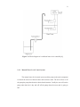
One of the traditional water level control system is float switches [1, 13]. The
floating balls will be used as the sensors for level detection, which is depicted in
7
figure 2.1. As shown in the figure, the controller has two floating balls (will be called
ball A and ball B hereafter) placed at two levels (will be called level H and level L
hereafter). The switch of the pumping motor is set to be on or off according to the
positions of the floating balls. The operation theory is as shown in the following table
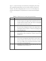
2.1[1]
Table 2.1: Traditional water level control system operation theory
Step
1
Description
When the water level of the water tank is lower than level L, due to
the effect of gravity, the weights of ball A and ball B will be heavy
enough to make the switch be closed. This will turn on the pumping
water to pump water into the water tower.
2
When the water level reaches level L, ball B will float on the water
due to the effect of floating force. However, the weight of ball A is
still enough to make the switch be on. Therefore, the pumping motor
keeps on pumping water.
3
When the water reaches level H, ball A and ball B have no weight on
the switch due to effect of floating force. Therefore, the motor stops
pumping water.
4
When the residents use the water, the water will be lower than level
H first. In this case, though the weight of ball A is on the switch, it is
not heavy enough to turn on the motor. If the water is lower than
level L, the weights of ball A and ball B will make the switch be
closed and turn on the pumping motor.
5
Repeating the above procedure, the water in the water tower can be
controlled between level H and level L.
8
Figure 2.1: Block diagram of a traditional water level controller [1]
2.2.2
Manual Water Level Control System
The manual water level control system used the pump as the main component
to control the water level between base tank and tower tank. The user will on or off
the pump the pump based on their desired and situation. Usually the user will on the
pump when their tab is dry and will off the pump when the tower tank is going to
full.
9
2.2.3
Automatic Water Level Control System
To overcome the traditional water level control system problems and to avoid
manual control system, a lot of companies and people come out with their own water
level controller design. Mostly, people have tried to detect and control the water level
in a digital manner [1]. The automatic system was designed to automatically control
of water pump motor, which ensures constant reserve of water in storage tanks [4]. It
also takes over the task at indicating and controlling the water level in the water
tower tank [5]. Usually, there are two type of design that they always used. The first
one is to install a sensor to detect the water level of the basement tank. When the
water level in the basement tank is less than a prescribed value, the power of the
pumping motor will be shut down to prevent ‘dry run’ to avoid the motor burn [1,6].
The second way is to install a sensor to detect the water level of the tower tank. The
sensors sense the presence of water. If there is no water then microcontroller gives
control signal to start the motor and if there is sufficient water in the field then the
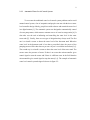
microcontroller give control signal to stop the motor [1,6]. The example of automatic
water level control system designed is shown in figure 2.2:
10
Figure 2.2: Block diagram of automatic water level control system
The operation theory of this system is the Automatic Water Level Controller
will automatically START the pump set as soon as the water level falls below the
predetermined level (usually kept half or 2/3rd ) tank and shall SWITCH OFF the
pump set as soon as tank is full or water level in the lower tank is at below minimum
level. The LED indicator was built for showing FULL (STOP), EMPTY Levels in
Upper Tank (START) and Lower Tank (STOP) and to present either the Motor in
ON or OFF mode. When the water reached at specific level such as maximum or
minimum levels, the LED that represents that level will be ON.
11
2.3
Advantages and Disadvantages
Every design and type of water level control system has their own advantages
and disadvantages. However, people always come with a new creation and design to
improve the water levels control system. This creation will help people to get better
in their life [5].
2.3.1
Traditional Water Level Control System
As mention before, the floating balls will be use as the sensors for level
detection for the traditional water level controller system. This control system has the
advantages of simple structure , low cost [1, 3] by using floating balls as the sensors
for water level control, and the ability of the operator to check their function by
manually tilting the float switches [3]. However, the placement of the contact switch
for the pumping motor at the top of water tower may corrode the contact point of the
switch due to the humidity effect. This will cause the switch to mal-function.
Meanwhile, since there are no means to detect the water level of the basement water
tank, it is possible that the pumping water will be burned if there is water level in the
basement water tank is too low [1].
2.3.2
Manual Water Level Control System
The advantage of this control system is can be avoid the wastage of electricity
and water. The problem is when the user fails to do manual operating in time it may
12
cause non availability or the wastage in electricity and water. This process also needs
to repeat every time [1, 2].
2.3.3
Automatic Water Level Control System
Compared with the traditional water level control system, the digital or
automatic water level control system has the following advantages:
1. No mechanical switch is used. Therefore, there will be no corrosion problem
[1].
2. When the water level is lower than a prescribed value, the power of the
pumping motor will be shut down to prevent the damage of the motor [1, 16]
at the same time will increases the pump set life [3-8].
3. Save electricity and water by ensure no outflow and dry running [1 -8].
And the disadvantages of this system are [1]:
1. The water levels of the water tower and the water tank are not displayed.
2. When the water level of the water tank is too low, only the power is shut
down. However, the status of the water tank level is still unknown.
3. Several digital IC components are needed in implementation. This will
increase the complexity of designing.
13
2.4
Available Design/Project
Currently, a lot of companies or person was come out with new design water
level control called AWLCS. The AWLCS is using controller design to
automatically switch on / off motor to maintain water level in the over head tank [38]. The design or project that was consists of one control unit and level sensor. The
level sensor continuously monitors water level and sends signal to switch on the
motor when the water level in the tank becomes below the low set limit and switch
off the motor when the water level reaches the high level setting also switches off
when the sump water is exhausted before filling overhead tank, pump running dry .
The level settings can be easily done by positioning the low level and high level
sensing weights in required level [6].
There are lots of advantages by using automatic water level control system.
With this system we can decide what the water levels for operations of pump set in
upper/lower tanks [6]. The Automatic water level controller to ensure no overflows
or dry running of pump there by saves electricity and water. The pump set life can be
increases by setting the water level is lower than a prescribed value, the power of the
pumping motor will be shut down to prevent the damage of the motor [3-8].
The problem with the design is there are no indicator to show the current
level of water in base tank and tower tank. The system was design to automatically
running the pump base on the level of water at tower water. The pump will be
automatically ON when the level of water reach some specific point that was setup.
However, the pumping motor will be stopped base on the level of water in both
tanks. There is no problem if the pump motor stopped due to tower tank because it
means that tank is already full. The problem occur when the pump stop due to there
is not enough water in the base tank and there is no indicator to show the current
level of water in tower tank to alert the user.
14
CHAPTER 3
METHODOLOGY
3.1
Hardware Implementation
The project for AWLCS consists of main board, sensor boards, relay board
and power supply board. Each board has their own function and later works as one
system. Main board consists of microcontroller, LCD 16x2 and LED. Sensor boards
consist of LM324 and circuit for water level sensor probe for tower tank and base
tank. Relay board consists of relay circuit for water pump. The last board was power
supply board consists of 5V regulator.
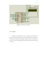
3.2
Main board
Main board is the heart of overall project for AWLCS that function as a
monitoring system, control system and display system. The main board will control
output interface and display interface and also to process data receive from sensor
interface circuit. Figure 3.1 below shows the main board for AWLCS project
15
Figure 3.1: Main board
The board consists of:
1. PIC18F452 as a microcontroller
2. Display circuit
i.
LCD 16x2
ii.
LED
16
3.2.1
Microcontroller PIC 18F452
Microcontrollers are general purposes microprocessors which have additional
parts that allow them to control external devices. A microcontroller is a very
powerful tool that allows a designer to create sophisticated I/O data manipulation
algorithms. The simplest microcontroller architecture consists of a microprocessor,
memory and I/O. The microprocessor consists of a central processing unit (CPU) and
the control unit (CU). Memory is the important part of a microcomputer system.
There are basically five types of memories:
a) Random Access Memory (RAM)
b) Read Only Memory (ROM)
c) Erasable Programmable Read Only Memory (EPROM)
d) Electrically Erasable Programmable Read Only Memory (EEPROM)
e) Flash (EEPROM)
The PIC families of microcontroller are developed by Microchip Technology
Inc. PIC microcontrollers have simple architectures and there are many versions of
them, some with only small enhancement and some offering more features. In this
project, the microcontroller used is PIC 18F452. Key features of this microcontroller
are as stated in Table 3.1
17
Table 3.1: Key features of PIC 18F452 compared to other PIC microcontrollers
18
3.2.1.1
Pin Description of the PIC 18F452
The PIC 18F452 consists of 40-pin device with the following pins:
MCLR
Master clear input
RB4-RB7
Bi-directional port B pins. Some of these pins are also used as
programming pins.
RB0-RB2
Bi-directional port B pins. Also, external interrupt pin
INT0-INT2
RB3/CCP2
Bi-directional port B pins. Also, Capture2 input/Compare2
output/PWM2 output
Figure 3.2: Pin diagram of PIC 18F452
RA0 - RA1
Bi-directional port A pins. Also, analog input pins
RA2
Bi-directional port A pins. Also, analog input pin and analog negative
reference voltage.
RA3
Bi-directional port A pins. Also, analog input pin and analog positive
reference voltage
RA4
Bi-directional port A pins. Also, clock input to Timer() module.
19
RA5
Bi-directional port A pins. Also, analog input and synchronous serial
port slave select pin
RE0-RE2
Bi-directional port E pins. Also, analog input and parallel slave port
control pins
RD0-RD7
Bi-directional port D pins. Also, parallel slave bus I/O pins.
VSS
Ground reference.
VDD
Positive power supply voltage.
OSC1-OSC2 Oscillator crystal inputs
RC0
Bi-directional port C pin. Also, Timer1 oscillator output or Timer1
clock
input.
RC1
Bi-directional port C pin. Also, Timer 1oscillator output or Capture2
input/Compare2 output/PWM2 output
RC2
Bi-directional port C pin. Also, Capture21 input/Compare1
output/PWM1output
RC3
Bi-directional port C pin. Also, synchronous serial clock input/output
for
SPI/ I2C mode.
RC4
Bi-directional port C pin. Also, the SPI Data In and I2C Data I/0
RC5
Bi-directional port C pin. Also, SPI Data Out
RC6
Bi-directional port C pin. Also, USART asynchronous transmit or
synchronous clock.
RC7
Bi-directional port C pin. Also, USART asynchronous receive or
synchronous data.
The amount of program memory provided by the PIC 18F452 should be
sufficient for many level monitoring and control applications. These applications also
need large data memories since most of the operations use many operation loops,
requiring several bytes to store a single variable in the data memory.
20
The function microcontroller is to control the whole operation for the system.
The data received from water level sensor circuit will be connected to the
microcontroller input. Besides that LCD 16x2, LED and relay for the pump will be
connected to the microcontroller output.
The basic circuits for the microcontroller are crystal oscillator and reset
switch.This project used 20MHz crystal oscillator to produce high frequency and
give the best performance. There are 4MHz internal crystal oscillator built inside the
microcontroller; hence the total crystal oscillation is 80MHz. The push button reset
switch is used to reset the whole system with the latest memory are stored at the
RAM.
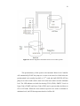
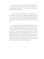
Based on Figure 3.3, the water level sensor for tower tank and base tank was
connected to PORTA (RA0, RA1, RA2 and RA3) and (RA4, RA5 and RA6) as an
input to the microcontroller. PORTA function as a digital input can be processed by
the microcontroller. RA3 is used as a voltage reference for analogue to digital
converter which is used to get full scale value for the input. LCD 16x2 pins (DB4,
DB5, DB6, DB7, E and RS) are connected to PORTC (RC4, RC5, RC6, RC7) and
PORTD (RD0 and RD1). Besides that PORTB (RB0, RB1, RB2, and RB3) are
connected to LED pump, LED heater, LED lamp and LED light. While, PORTB
(RB4, RB5, RB6, and RB7) are connected to relay pump, relay heater, relay lamp
and relay fan. Buzzer, LED heater, push button heater and push button pump
manually are connected to PORTD (RB4, RB5, RB6, and RB7).
21
Figure 3.3: PIC 18F452 pin connection
3.2.2
LCD 16x2
This project used LED and LCD 16x2 as a display system. The LEDs will
turn on based on the amount of water level that was sensed by the sensor. The LCD
16x2 has two rows and each row can display 16 characters. First row will display the
current level of water for both tanks and the second level will display either the pump
is on or off.
22
3.3
Water Level Sensor Board
For this project there are two tanks which are tower tank and base tank. There
are four levels that need to be displayed for tower tank and three levels for the base
tank. Base tank water level contains of pump that used to pump water from the base
tank to tower tank. To prevent the pump from burn out the pumping system will stop
if the water inside the base water tank is empty.
e
The
he pump will not turn on even
though there are changes in the parameter
parameter until the base tank is filled with water.
Figure 3.4 in the paragraph shows the water level sensor board for the system.
Figure 3.4: Sensor board
show water level sensor schematic circuit. Water level sensor
Figure 3.5 shows
used the comparator LM324 (low power quad operational amplifiers). If water sensor
probe detect the water then the voltage output from LM324 to the PIC is 0V and if
water sensor probe do not detect the water then the voltage from LM324 to the PIC is
about 3.6V. From the analysis there are two different voltages, 3.6V (sensor probe do
not sense water) and 0V (sensor probe sense water).
23
The microcontroller was programmed based on this analysis. When
microcontroller sense 0V (sensor probe sense water) from water level sensor output,
the LEDs and LCD will on and display the current level of water depend on the
tanks. The output from microcontroller that controls the relay pump will trigger or
not based on the condition that was programmed.
Figure 3.5: Water level sensor schematic diagram.
24
3.4
Relays Board
Figure 3.6: Relay board
This project used 5V single pole double throw (SPDT) relay to interface
between microcontroller and pump. 5V SPDT relay is a device consisting of a coil of
wire wrapped around an iron core. When electricity is applied to the coil of wire, it
becomes magnetic, hence the term electromagnet applied. The pin1, 2 and 3 are an
SPDT switch controlled by the electromagnet. When electricity is applied to pin4 and
pin5, the electromagnet acts upon the SPDT switch so that the pin3 and pin1 are
connected. When the electricity is disconnected, then the pin2 and pin1 are
connected. It is important to note that the electromagnet is magnetically linked to the
switch but the two are NOT linked electrically, hence this can avoid any harm to the
microcontroller.
25
Figure 3.7: SPDT relay circuit diagram
Figure 3.7 shows the schematic diagram for SPDT relay connection on the
board. Based on the figure pin no.4 connect to 5V Vcc, pin no 5 connect to transistor
2N4401, pin no. 1 and 3 connect to pump wire. Relay circuit used the transistor
because the current from microcontroller is not enough to trigger on the relay, hence
the transistor act as current amplifier that will gain the current from microcontroller.
3.5
Power Supply Board
This project used 5v to regulate 5V voltage from battery that supplies 12V
voltage. 5V power supply connected to main board, sensor board and relay board.
Figure 3.8 below shows the power supply board for the system.
26
Figure 3.8: Power Supply Board
3.6
Software Implementation
Software implementation is the important part of this project and takes the
longest period of analysis and research. There were two software were used in this
project. The first one is Visual Basic 2008 that was used to design a VWLCS. The
second one is MikroC Pro compiler. MikroC Pro compiler with MCC18 was used to
write C language program for the prototype of Automatic Water Level Control
System (AWLCS). This software will convert the C++ language to HEX file that can
be read by the microcontroller.
27
3.7
Virtual Water Level Control System (VWLCS)
The VWLCS for this project was designed by using visual basic 2008
software. Visual basic can develop a Graphical User Interface (GUI) to provide
visual graphical output on the computer monitor. The GUI is used to display or show
how the prototype for the other part of this project will work. By using visual basic
software, the VWLCS was design to be able to operate in manual mode and
automatic mode. The coupled of tanks was created to represent tower tank and base
tank. Four levels which is reference level, level 1, level 2 and full level are pointed to
the tower tanks to represent the level water. Minimum level and maximum level are
pointed to the base tank to represent the levels of water in the base tank. The design
is exactly the same for both manual and automatic mode.
3.7.1
Manual Mode
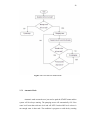
In the manual mode the user can choose which level in tower tank to system
fill up the water from base tank to the chosen level in tower tank. The system flow
graph for the manual mode is shows in figure 3.9 below:
28
Figure 3.9: Flow chart for manual mode
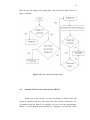
3.7.2 Automatic Mode
Automatic mode means the user just need to push the START button and the
system will be always running. The pumping motor will automatically ON if the
water level lower than reference level and will OFF if reached full level or there is
not enough water in base tank. The condition is program to avoid the dry running
29
that will cause the damage to the pump motor. The system flow chart is shown in
figure 3.10 below:
Figure 3.10: Flow chart for automatic mode
3.8
Automatic Water Level Control System (AWLCS)
Another part of this project is to build a prototype of AWLCS that will
operate in automatic mode only. The system flow chart is shown in the figure 3.10.
As mention before the MikroC Pro compiler was used to run the programming.
MikroC is used to program microcontroller in C language. It will provide all the
30
necessary programming needs, from the input set point to the output implementation
of the system. Figure 3.11 shows the view of MikroC for PIC software used in the
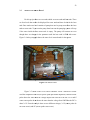
project. MicroC is a powerful, feature rich development tool for PIC
microcontrollers. It provides a successful match featuring highly advanced IDE,
ANSI compliant compiler, broad set of hardware libraries, comprehensive
documentation and plenty of ready-to-run examples.
Figure 3.11: MikroC Pro Compiler for PIC software
MikroC allows quick development and deployment of complex applications.
It enables C source code writing using highly advanced Code Editor. The included
MikroC libraries could be used to speed up the development of data acquisition,
memory, displays, conversions, and communications. Code Explorer helps user to
monitor the program structure, variables, and functions. Any programmers could be
used to generate the commented, human-readable assembly and standard HEX.
Plenty of examples are also provided to be expanded, developed and used as building
breaks in user project.
31
There are two parts of the program which are the main program and
subroutine part. The microcontroller will run the main program aided by the
subroutines. The subroutine includes how the level of water input is read by the
microcontroller. The program in C language can be referred in Appendix A.
3.9
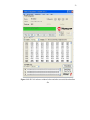
PICkit 2 v2.55 software with USB ICSP PIC Programmer
This project used PICkit 2 v2.55 software to download the hex file project
into the PIC18F452. The USB ICSP PIC programmer used to interface
betweenPIC18F452 with the software PICkit 2 v2.55. Figure 3.12 and figure 3.13
show the PICkit2Programmer window before and after successful download hex file.
32
Figure 3.12: PICkit2 Programmer
33
Figure 3.13: PIC kit2 software window before and after successful download hex
file
34
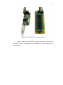
Figure 3.14: USB ICSP PIC programmer diagram
Figure 3.14 shows the USB ICSP PIC programmer diagram. The function of
this USB ICSP PIC programmer is to download hex file from computer to the
microcontroller.
36
CHAPTER 4
RESULT AND DISCUSSION
4.1
Result
The VWLCS and the prototype of AWLCS successfully show the levels of
water in tower tank and base tank and control the pump automatically. The VWLCS
are designed to operate in manual mode and automatic mode. The AWLCS are
designed to operate in automatic mode only. AWLCS used LED as indicator for each
level and also use the LCD to display the current levels of water and to display either
the pump motor is on or off.
The prototype of AWLCS needs a hardware and software development. This
project use a nail as a probe sensor to detect the level of water and it work properly.
The controller system for AWLCS was PIC18F452. This project successfully
program the microcontroller that be able to control the sensor as an input also control
the output such as LCD, LED and the pump motor. The development of prototype
for the AWLCS need a testing process and experiment to conduct to make sure the
system work properly especially in hardware development.
36
4.2
Discussion
4.2.1
Testing: PIC 18F452 Pins
It is really important to check either the PIC pin work or not to make sure our
project will work as plan. The procedures and result will discuss in section below:
4.2.1.1
4.2.1.2
Procedures
1)
Program the PIC pins that will be used as a output to the LED.
2)
Connect the pins port to the LED.
3)
Supply 5V of voltage to the circuit.
4)
Light of LED will be recorded to represent the pins is functioning.
Result and Analysis
Table 4.1: Light of LED
PIC Pin
Light of LED
RA0
ON
RA1
ON
RA2
ON
RA3
ON
RA4
ON
RA5
ON
RB0
ON
37
RB1
ON
RB2
ON
RB3
ON
RB4
ON
RC0
ON
RC1
ON
RC2
ON
RC3
ON
RC4
ON
RC5
ON
RC6
ON
RC7
ON
RD0
ON
RD1
ON
RD2
ON
RD3
ON
RD4
ON
RD5
ON
RE0
ON
RE1
ON
RE2
ON
The result show that the LED is on which means the pins port give an output
voltage and that pins can be used.
4.2.2
Experiment: Probe Sensor testing
The probe sensor to sense the water for this project was my own design. A
calibration need to be done to measure the sensitivity of my probe sensor. A nail is
used as probe sensor. The main components in this experiment is sensor board circuit
38
which consists of variable resistor, that connected to the LM 324 which is used as the
voltage comparator, nail as a probe sensor and multi meter to measure the input and
output voltage for LM 324. The procedures and result is discussed in the following
section:
4.2.2.1
Procedure
1)
Connected the nail to the water level sensor circuit.
2)
Voltage of 5V is supplied to the circuit.
3)
Set the voltage reference for LM 324 equal to 3.7V using variable resistor.
4)
Measure and record the input and output voltage for LM 324.
5)
Put the nail in the water.
6)
Measure and record the input and output voltage for LM 324.
4.2.2.2
Result and analysis
Table 4.2: Probe sensor measurement
Probe sensor
Vin
Vout
Sense no water
4.78 V
3.6 V
Sense water
2.11 V
0V
From the data measurement in the Table 4.2, there is a different voltage for
input and output voltage when the nail sense water and do not sense water. The
programming can be developed from the analysis of the data. The output voltage of
39
3.6V will be read as digital value 1 and 0V will be read as digital value 0 by
microcontroller which will indicate the water levels that was sense by the probe
sensors.
4.3
Result and Analysis for VWLCS
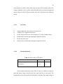
Figure 4.1 in the paragraph show that the system firstly will ask the user the
operating mode for the system. After the mode was choosing, the users need to click
the start button first to start the system. Figure 4.2 shows the system in manual mode
and Figure 4.3 show the system in the automatic mode.
Figure 4.1: VWLCS selecting mode
40
The current level that shown in the figure 4.2 is level 2 for the tower tank and
at minimum level for base tank. The system will continuosly display the levels of
water and change water level reach at new level for both tank. For the manual mode
the user can stop the pumping process at any level by click the stop button.
Figure 4.2 Manual mode for VWLCS
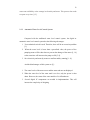
The figure 4.3 shows the system in the automatic mode. The current level for
tower tank is at level 2 and at minimum level for base tank. This system will stop the
pumping process automatically when the level of water reach at full level for tower
tank or the level at base tank lower than minimum level.
41
Figure 4.3 Automatic mode for VWLCS
4.4
Result and Analysis for AWLCS
After the testing process was done for mikrocontroller port and water level
sensor, the complete circuit for AWLCS will be designed and built. The next
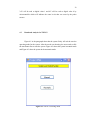
required process is to test the system in the real enviroment. This is important
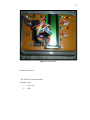
process that will determine either the system is successful or not. The figure 4.4
shows the display device that will be display the level of water in the tanks.
42
Figure 4.4: AWLCS Display system
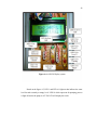
Based on the figure 4.5, LED 1 and LED 6 is light on that indicate the water
level for tank currently at empty level. LED 10 which represent for pumping process
is light off means the pump is off. The LCD will display the result.
43
Figure 4.5: Result for AWLCS
Based on the figure 4.6, LED 1, LED 2 for tower tank is light on which
means the current water level is at warning level. The LED 6 is light on that indicate
the water level for base tank currently at empty level. LED 10 which represent for
pumping process is light off means the pump is off. The LCD will display the result.
44
Figure 4.6: Result for AWLCS
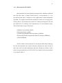
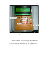
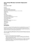
Based on the figure 4.7 in the paragraph, LED 1, LED 2, LED 3 and LED 4
for tower tank is light on which means the current water level is at level 2. The LED
6, LED 7 and LED 8 is light on that indicate the water level for base tank currently at
middle level. LED 10 which represent for pumping process is light on means the
pump is on. The LCD will display the result.
45
Figure 4.7: Result for AWLCS
47
CHAPTER 5
CONCLUSION AND FUTURE WORK
5.1
Conclusion
As mention in chapter 1 before, the objective of this project is to display the
levels of water in house tanks. Another objective of this project is to control the
pumping motor automatically to avoid dry running that maybe cause damage to the
pump motor. A VWLCS and AWLCS are design and build to achieve the objectives
of the project.
This project has successfully accomplished the objectives. The VWLCS and
AWLCS successfully show the levels of water for tower tank and base tank and also
able to control the pump automatically. The prototype of AWLCS used LEDs and
LCD as display device that will display the levels of water on show either the pump
motor is on or off.
The achievement of the objective for the project will alert the user about the
current water storage in their tanks that will help them to plan and use the water in
47
effective way. This system also able to avoid the pump from burn because the pump
only running when there enough water in base tank.
5.2
Future Work
Even though this project is successfully design and build, improvement can
be done in order to make the system more efficient and effectively. The system can
be interface by GUI that will help the user to check the levels of water in their house
tanks on computer screen. Interfacing with GUI also will help the user to control
pump motor manually which give more variety to the user.
Another that can be improved is the probe sensor. Although the nail work
properly as a sensor but if we used it for a long time it will be corrosion. The probe
sensor will not working effectively.
48
REFERENCES
[1]
Shou Quan Lu. A Circuit for Water Level Detection and Control. Graduate
Student, Institute of Electrical Engineering, National Yunlin University of
Science and Technology, Touliu, Yunlin 640, Taiwan.
[2]
Article by Swagatam : Build this simple Electronic Water Level Controller
BRIGHT HUB ENGINEERING
http://www.brighthub.com/engineering/electrical/articles/68342.aspx
[3]
Article by Digitek : Automatic Water Level Controller
http://www.digitek.in/
[4]
Article by COSY COMMUNICATIONS “SAVE WATER & ENERGY BY
AUTOMATIC WATER LEVEL CONTROLLER/ WATER LEVEL
INDICATOR”.
http://www.cosycommunications.com/
[5] Article by Arihant : Automatic Water Level Controller
http://www.ramneek-arihant.com/awc.html
49
[6] Article by ELWER SYSTEMS: Automatic Water Level Controller
http://www.indiamart.com/elwer-systems/products.html
[8] Article by Manufacturers of Automatic Water Level Controller in India,
Manufacturers of Float Switches in India.htm
http://statuswaterlevelcontroller.com/sawlc.htm
[9] Article by LABGEAR INDIA: Automatic Water Level Controller
http://www.labgearindia.com/
[10] Thesis by MUHAMMAD NASIRUDDIN BIN MAHYUDDIN
MODEL REFERENCE ADAPTIVE CONTROL
OF COUPLED TANK LIQUID LEVEL CONTROL SYSTEM
Faculty of Electrical Engineering
Universiti Teknologi Malaysia; November 2005
[11] Microchip Technology Inc. “PIC18f452 Data Sheet” Americas: Data Sheet.
2001
[12] STMMicroelectronics LM 324 Low Power Quad Operational Amplifiers.
Italy: Data Sheet. June 1999.
[13] mikroElektronika. (2006). mikroC Making it Simple: User’s manual.
www.mikroC.com
APPENDIX A
//-------------------------------------LCD PIN CONNECTION--------------------------------
sbit LCD_RS at RD1_bit;
sbit LCD_EN at RD0_bit;
sbit LCD_D7 at RC7_bit;
sbit LCD_D6 at RC6_bit;
sbit LCD_D5 at RC5_bit;
sbit LCD_D4 at RC4_bit;
//------------------------------------LCD MODULE CONNECTION-------------------------
sbit LCD_RS_Direction at TRISD1_bit;
sbit LCD_EN_Direction at TRISD0_bit;
sbit LCD_D7_Direction at TRISC7_bit;
sbit LCD_D6_Direction at TRISC6_bit
sbit LCD_D5_Direction at TRISC5_bit;
sbit LCD_D4_Direction at TRISC4_bit;
//----------------------------------------------CONFIGURATION-----------------------------#pragma config OSC = HS
#pragma config WDT = OFF
51
#pragma config LVP = OFF
#pragma config BOR = OFF
//-------------------------------------------DEFINE I/O PORT----------------------------------
#define Probe1 PORTA.F0
#define Probe2 PORTA.F1
#define Probe3 PORTA.F2
#define Probe4 PORTA.F3
#define Probe5 PORTA.F4
#define Probe6 PORTA.F5
#define Probe7 PORTE.F0
#define LevelLED1 PORTB.F0
#define LevelLED2 PORTB.F1
#define LevelLED3 PORTB.F2
#define LevelLED4 PORTB.F3
#define WLED8 PORTD.F4
#define LevelLED5 PORTB.F4
#define LevelLED6 PORTE.F1
#define LevelLED7 PORTE.F2
#define WLED9 PORTD.F5
#define PUMPLED PORTD.F2
#define PUMPRELAY PORTD.F3
//----------------------FUNCTION PROTOTYPE & LOOP CONDITION----------------
void Move_Delay()
{
// Function used for text moving
52
Delay_ms(500);
// You can change the moving speed
here
}
void U()
{
Lcd_Cmd(_LCD_CLEAR);
// Clear display
Lcd_Out(1,2,"TANKS EMPTY");
// Write text in first row
Lcd_Out(2,2,"PUMP OFF");
// Write text in second row
WLED8 = 1;
LevelLED1=0;
LevelLED2=0;
LevelLED3=0;
LevelLED4=0;
WLED9 = 1;
LevelLED5=0;
LevelLED6=0;
LevelLED7=0;
PUMPLED=0;
PUMPRELAY=0;
}
void V(void)
{
Lcd_Cmd(_LCD_CLEAR);
// Clear display
Lcd_Out(1,2,"WARNING AND EMPTY"); // Write text in first row
Lcd_Out(2,2,"PUMP OFF");
WLED8 = 0;
LevelLED1=1;
LevelLED2=0;
LevelLED3=0;
LevelLED4=0;
WLED9 = 1;
LevelLED5=0;
LevelLED6=0;
// Write text in second row
53
LevelLED7=0;
PUMPLED=0;
PUMPRELAY=0;
}
void X(void)
{
Lcd_Cmd(_LCD_CLEAR);
// Clear display
Lcd_Out(1,2,"LEVEL 1 AND EMPTY");
// Write text in first row
Lcd_Out(2,2,"PUMP OFF");
// Write text in second row
WLED8 = 0;
LevelLED1=1;
LevelLED2=1;
LevelLED3=0;
LevelLED4=0;
WLED9 = 1;
LevelLED5=0;
LevelLED6=0;
LevelLED7=0;
PUMPLED=0;
PUMPRELAY=0;
}
void Y(void)
{
Lcd_Cmd(_LCD_CLEAR);
// Clear display
Lcd_Out(1,2,"LEVEL 2 AND EMPTY");
// Write text in first row
Lcd_Out(2,2,"PUMP OFF");
// Write text in second row
WLED8 = 0;
LevelLED1=1;
LevelLED2=1;
LevelLED3=1;
LevelLED4=0;
WLED9 = 1;
LevelLED5=0;
54
LevelLED6=0;
LevelLED7=0;
PUMPLED=0;
PUMPRELAY=0;
}
void Zat(void)
{
Lcd_Cmd(_LCD_CLEAR);
// Clear display
Lcd_Out(1,2,"FULL AND EMPTY");
// Write text in first row
Lcd_Out(2,2,"PUMP OFF");
// Write text in second row
WLED8 = 0;
LevelLED1=1;
LevelLED2=1;
LevelLED3=1;
LevelLED4=1;
WLED9 = 1;
LevelLED5=0;
LevelLED6=0;
LevelLED7=0;
PUMPLED=0;
PUMPRELAY=0;
}
void Fat(void)
{
Lcd_Cmd(_LCD_CLEAR);
// Clear display
Lcd_Out(1,2,"EMPTY AND MIN LEVEL");
// Write text in first row
Lcd_Out(2,2,"PUMP ON");
// Write text in second
row
WLED8 = 1;
LevelLED1=0;
LevelLED2=0;
LevelLED3=0;
55
LevelLED4=0;
WLED9 = 0;
LevelLED5=1;
LevelLED6=0;
LevelLED7=0;
PUMPLED=1;
PUMPRELAY=1;
}
void G(void)
{
Lcd_Cmd(_LCD_CLEAR);
// Clear display
Lcd_Out(1,2,"WARNING AND MIN LEVEL");
// Write text in first row
Lcd_Out(2,2,"PUMP ON");
// Write text in second
row
WLED8 = 0;
LevelLED1=1;
LevelLED2=0;
LevelLED3=0;
LevelLED4=0;
WLED9 = 0;
LevelLED5=1;
LevelLED6=0;
LevelLED7=0;
PUMPLED=1;
PUMPRELAY=1;
}
void H(void)
{
Lcd_Cmd(_LCD_CLEAR);
// Clear display
Lcd_Out(1,2,"LEVEL 1 AND MIN LEVEL");
//Write text in first row
Lcd_Out(2,2,"PUMP ON");
// Write text in second
row
WLED8 = 0;
56
LevelLED1=1;
LevelLED2=1;
LevelLED3=0;
LevelLED4=0;
WLED9 = 0;
LevelLED5=1;
LevelLED6=0;
LevelLED7=0;
PUMPLED=1;
PUMPRELAY=1;
}
void Iat(void)
{
Lcd_Cmd(_LCD_CLEAR);
// Clear display
Lcd_Out(1,2,"LEVEL 2 AND MIN LEVEL");
// Write text in first row
Lcd_Out(2,2,"PUMP ON");
// Write text in second
row
WLED8 = 0;
LevelLED1=1;
LevelLED2=1;
LevelLED3=1;
LevelLED4=0;
WLED9 = 0;
LevelLED5=1;
LevelLED6=0;
LevelLED7=0;
PUMPLED=1;
PUMPRELAY=1;
}
void J(void)
{
Lcd_Cmd(_LCD_CLEAR);
// Clear display
Lcd_Out(1,2,"FULL AND MIN LEVEL");
// Write text in first row
57
Lcd_Out(2,2,"PUMP OFF");
// Write text in second
row
WLED8 = 0;
LevelLED1=1;
LevelLED2=1;
LevelLED3=1;
LevelLED4=1;
WLED9 = 0;
LevelLED5=1;
LevelLED6=0;
LevelLED7=0;
PUMPLED=0;
PUMPRELAY=0;
}
void K(void)
{
Lcd_Cmd(_LCD_CLEAR);
// Clear display
Lcd_Out(1,2,"EMPTY AND MID LEVEL");
// Write text in first row
Lcd_Out(2,2,"PUMP ON");
// Write text in second
row
WLED8 = 1;
LevelLED1=0;
LevelLED2=0;
LevelLED3=0;
LevelLED4=0;
WLED9 = 0;
LevelLED5=1;
LevelLED6=1;
LevelLED7=0;
PUMPLED=1;
PUMPRELAY=1;
}
void L(void)
58
{
Lcd_Cmd(_LCD_CLEAR);
// Clear display
Lcd_Out(1,2,"WARNING AND MID LEVEL");
// Write text in first row
Lcd_Out(2,2,"PUMP ON");
// Write text in second
row
WLED8 =0;
LevelLED1=1;
LevelLED2=0;
LevelLED3=0;
LevelLED4=0;
WLED9 = 0;
LevelLED5=1;
LevelLED6=1;
LevelLED7=0;
PUMPLED=1;
PUMPRELAY=1;
}
void M(void)
{
Lcd_Cmd(_LCD_CLEAR);
// Clear display
Lcd_Out(1,2,"LEVEL 1 AND MID LEVEL");
// Write text in first row
Lcd_Out(2,2,"PUMP ON");
// Write text in second
row
WLED8 = 0;
LevelLED1=1;
LevelLED2=1;
LevelLED3=0;
LevelLED4=0;
WLED9 = 0;
LevelLED5=1;
LevelLED6=1;
LevelLED7=0;
PUMPLED=1;
59
PUMPRELAY=1;
}
void Nat(void)
{
Lcd_Cmd(_LCD_CLEAR);
// Clear display
Lcd_Out(1,2,"LEVEL 2 AND MID LEVEL");
// Write text in first row
Lcd_Out(2,2,"PUMP ON");
// Write text in second
row
WLED8 = 0;
LevelLED1=1;
LevelLED2=1;
LevelLED3=1;
LevelLED4=0;
WLED9 = 0;
LevelLED5=1;
LevelLED6=1;
LevelLED7=0;
PUMPLED=1;
PUMPRELAY=1;
}
void O(void)
{
Lcd_Cmd(_LCD_CLEAR);
// Clear display
Lcd_Out(1,2,"FULL AND MIN LEVEL");
// Write text in first row
Lcd_Out(2,2,"PUMP OFF");
// Write text in second
row
WLED8 = 0;
LevelLED1=1;
LevelLED2=1;
LevelLED3=1;
LevelLED4=1;
WLED9 = 0;
LevelLED5=1;
60
LevelLED6=1;
LevelLED7=0;
PUMPLED=0;
PUMPRELAY=0;
}
void Pat(void)
{
Lcd_Cmd(_LCD_CLEAR);
// Clear display
Lcd_Out(1,2,"EMPTY AND MAX LEVEL");
// Write text in first row
Lcd_Out(2,2,"PUMP ON");
// Write text in second
row
WLED8 = 1;
LevelLED1=0;
LevelLED2=0;
LevelLED3=0;
LevelLED4=0;
WLED9 = 0;
LevelLED5=1;
LevelLED6=1;
LevelLED7=1;
PUMPLED=1;
PUMPRELAY=1;
}
void Q(void)
{
Lcd_Cmd(_LCD_CLEAR);
// Clear display
Lcd_Out(1,2,"WARNING AND MAX LEVEL");
// Write text in first row
Lcd_Out(2,2,"PUMP ON");
// Write text in second
row
WLED8 = 0;
LevelLED1=1;
LevelLED2=0;
LevelLED3=0;
61
LevelLED4=0;
WLED9 = 0;
LevelLED5=1;
LevelLED6=1;
LevelLED7=1;
PUMPLED=1;
PUMPRELAY=1;
}
void Rat(void)
{
Lcd_Cmd(_LCD_CLEAR);
// Clear display
Lcd_Out(1,2,"LEVEL 1 AND MAX LEVEL");
// Write text in first row
Lcd_Out(2,2,"PUMP ON");
// Write text in second
row
WLED8 = 0;
LevelLED1=1;
LevelLED2=1;
LevelLED3=0;
LevelLED4=0;
WLED9 = 0;
LevelLED5=1;
LevelLED6=1;
LevelLED7=1;
PUMPLED=1;
PUMPRELAY=1;
}
void Sat(void)
{
Lcd_Cmd(_LCD_CLEAR);
// Clear display
Lcd_Out(1,2,"LEVEL 2 AND MAX LEVEL");
// Write text in first row
Lcd_Out(2,2,"PUMP ON");
// Write text in second
row
WLED8 = 0;
62
LevelLED1=1;
LevelLED2=1;
LevelLED3=1;
LevelLED4=0;
WLED9 = 0;
LevelLED5=1;
LevelLED6=1;
LevelLED7=1;
PUMPLED=1;
PUMPRELAY=1;
}
void T(void)
{
Lcd_Cmd(_LCD_CLEAR);
// Clear display
Lcd_Out(1,2,"FULL AND MAX LEVEL");
// Write text in first row
Lcd_Out(2,2,"PUMP OFF");
// Write text in second
row
WLED8 = 0;
LevelLED1=1;
LevelLED2=1;
LevelLED3=1;
LevelLED4=1;
WLED9 = 0;
LevelLED5=1;
LevelLED6=1;
LevelLED7=1;
PUMPLED=0;
PUMPRELAY=0;
}
63
//-------------------------------------LCD DISPLAY---------------------------------------
char txt1[] = "MOHD SHAIFUL IRUAN BIN MOHD ARIS";
char txt2[] = "WATER LEVEL CONTROL SYSTEM";
char txt3[] = "FINAL YEAR PROJECT";
char txt4[] = "PSM 1&2";
char i;
//------------------------------------------------MAIN------------------------------------------------
void main()
{
PORTA =0;
PORTB =0;
PORTC =0;
PORTD =0;
ADCON1 = 6;
TRISA=0b11111111;
TRISB=0b00000000;
TRISC=0b00000000;
TRISD=0b00000000;
TRISE=0b00000001;
//-------------------------------SUBROUTINE LCD SETTING-------------------------
Lcd_Init();
// Initialize LCD
Delay_ms(1000);
Lcd_Cmd(_LCD_CLEAR);
// Clear display
64
Lcd_Cmd(_LCD_CURSOR_OFF);
// Cursor off
Lcd_Out(1,2,txt3);
// Write text in first row
Lcd_Out(2,2,txt4);
/ Write text in second row
Delay_ms(2000);
Lcd_Cmd(_LCD_CLEAR);
// Clear display
Lcd_Out(1,1,txt1);
// Write text in first row
Lcd_Out(2,2,txt2);
// Write text in second row
Delay_ms(2000);
for(i=0; i<4; i++)
{
// Move text to the right 4 times
Lcd_Cmd(_LCD_SHIFT_RIGHT);
Move_Delay();
}
while(1)
{
// Endless loop
for(i=0; i<8; i++)
{
// Move text to the left 7 times
Lcd_Cmd(_LCD_SHIFT_LEFT);
Move_Delay();
}
for(i=0; i<8; i++)
{
// Move text to the right 7 times
Lcd_Cmd(_LCD_SHIFT_RIGHT);
Move_Delay();
}
Delay_ms(3000);
while(1)
{
if ((Probe1 ==1) && (Probe2 ==1) && (Probe3 ==1) && (Probe4 ==1) &&
(Probe5 ==1) && (Probe6 ==1)&&(Probe7==1))
U();
else if ((Probe1 ==0) && (Probe2 ==1) && (Probe3 ==1) && (Probe4 ==1) &&
(Probe5 ==1) && (Probe6 ==1)&&(Probe7==1))
65
V();
else if ((Probe1 ==0) && (Probe2 ==0) && (Probe3 ==1) && (Probe4 ==1) &&
(Probe5 ==1) && (Probe6 ==1)&&(Probe7==1))
X();
else if ((Probe1 ==0) && (Probe2 ==0) && (Probe3 ==0) && (Probe4 ==1) &&
(Probe5 ==1) && (Probe6 ==1)&&(Probe7==1))
Y();
else if ((Probe1 ==0) && (Probe2 ==0) && (Probe3 ==0) && (Probe4 ==0) &&
(Probe5 ==1) && (Probe6 ==1)&&(Probe7==1))
Zat();
else if ((Probe1 ==1) && (Probe2 ==1) && (Probe3 ==1) && (Probe4 ==1) &&
(Probe5 ==0) && (Probe6 ==1)&&(Probe7==1))
Fat();
else if ((Probe1 ==0) && (Probe2 ==1) && (Probe3 ==1) && (Probe4 ==1) &&
(Probe5 ==0) && (Probe6 ==1)&&(Probe7==1))
G();
else if ((Probe1 ==0) && (Probe2 ==0) && (Probe3 ==1) && (Probe4 ==1) &&
(Probe5 ==0) && (Probe6 ==1)&&(Probe7==1))
H();
else if ((Probe1 ==0) && (Probe2 ==0) && (Probe3 ==0) && (Probe4 ==1) &&
(Probe5 ==0) && (Probe6 ==1)&&(Probe7==1))
Iat();
else if ((Probe1 ==0) && (Probe2 ==0) && (Probe3 ==0) && (Probe4 ==0) &&
(Probe5 ==0) && (Probe6 ==1)&&(Probe7==1))
J();
else if ((Probe1 ==1) && (Probe2 ==1) && (Probe3 ==1) && (Probe4 ==1) &&
(Probe5 ==0) && (Probe6 ==0)&&(Probe7==1))
K();
else if ((Probe1 ==0) && (Probe2 ==1) && (Probe3 ==1) && (Probe4 ==1) &&
(Probe5 ==0) && (Probe6 ==0)&&(Probe7==1))
L();
else if ((Probe1 ==0) && (Probe2 ==0) && (Probe3 ==1) && (Probe4 ==1) &&
(Probe5 ==0) && (Probe6 ==0)&&(Probe7==1))
66
M();
else if ((Probe1 ==0) && (Probe2 ==0) && (Probe3 ==0) && (Probe4 ==1) &&
(Probe5 ==0) && (Probe6 ==0)&&(Probe7==1))
Nat();
else if ((Probe1 ==0) && (Probe2 ==0) && (Probe3 ==0) && (Probe4 ==0) &&
(Probe5 ==0) && (Probe6 ==0)&&(Probe7==1))
O();
else if ((Probe1 ==1) && (Probe2 ==1) && (Probe3 ==1) && (Probe4 ==1) &&
(Probe5 ==0) && (Probe6 ==0)&&(Probe7==0))
Pat();
else if ((Probe1 ==0) && (Probe2 ==1) && (Probe3 ==1) && (Probe4 ==1) &&
(Probe5 ==0) && (Probe6 ==0)&&(Probe7==0))
Q();
else if ((Probe1 ==0) && (Probe2 ==0) && (Probe3 ==1) && (Probe4 ==1) &&
(Probe5 ==0) && (Probe6 ==0)&&(Probe7==0))
Rat();
else if ((Probe1 ==0) && (Probe2 ==0) && (Probe3 ==0) && (Probe4 ==1) &&
(Probe5 ==0) && (Probe6 ==0)&&(Probe7==0))
Sat();
else if ((Probe1 ==0) && (Probe2 ==0) && (Probe3 ==0) && (Probe4 ==0) &&
(Probe5 ==0) && (Probe6 ==0)&&(Probe7==0))
T();
}