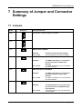
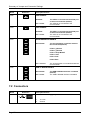
1
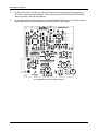
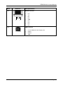
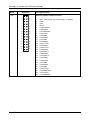
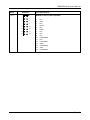
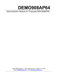
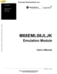
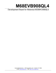
DEMO908JL16
Demonstration Board
for Freescale
MC68HC908JL16 Family
(32-Pin SDIP)
User’s Manual
Revision 1.0
Copyright © 2006 SofTec Microsystems®
DC01037
We want your feedback!
SofTec Microsystems is always on the look-out for new ways to improve its Products and
Services. For this reason feedback, comments, suggestions or criticisms, however small,
are always welcome.
Our policy at SofTec Microsystems is to comply with all applicable worldwide
safety and EMC/EMI regulations. Our products are certified to comply to the
European New Approach Directives and the CE mark is applied on all our
products.
SofTec Microsystems
E-mail (general information): [email protected]
E-mail (marketing department): [email protected]
E-mail (technical support): [email protected]
Web: http://www.softecmicro.com
Important
SofTec Microsystems reserves the right to make improvements to the inDART-One In-Circuit Programmer/Debugger, its
documentation and software routines, without notice. Information in this manual is intended to be accurate and reliable.
However, SofTec Microsystems assumes no responsibility for its use; nor for any infringements of rights of third parties which
may result from its use.
SOFTEC MICROSYSTEMS WILL NOT BE LIABLE FOR DAMAGES RESULTING FROM LOSS OF DATA, PROFITS, USE
OF PRODUCTS, OR INCIDENTAL OR CONSEQUENTIAL DAMAGES, EVEN IF ADVISED OF THE POSSIBILITY
THEREOF.
Trademarks
SofTec Microsystems is a registered trademark of SofTec Microsystems, Spa.
Freescale™ and the Freescale logo are trademarks of Freescale Semiconductor, Inc.
Microsoft and Windows are trademarks or registered trademarks of Microsoft Corporation.
PC is a registered trademark of International Business Machines Corporation.
Other products and company names listed are trademarks or trade names of their respective companies.
DEMO908JL16 User's Manual
Contents
1
2
Introduction 5
1.1
Overview 5
1.2
Package Contents 5
1.3
Supported Devices 5
1.4
Recommended Reading 5
1.5
Getting Technical Support 6
Hardware Features 7
2.1
3
4
5
6
7
8
Demonstration Board Features 7
Software Setup 9
3.1
Overview 9
3.2
Host System Requirements 9
3.3
Installing CodeWarrior Development Studio 9
3.4
Installing SofTec Microsystems Additional Components 10
Hardware Setup 11
4.1
First Connection 11
4.2
Power Supply 13
Operating Modes 15
5.1
Overview 15
5.2
Standalone Mode 15
5.3
Host Mode 15
Application Tutorial 17
6.1
Overview 17
6.2
Step-by-Step Tutorial 17
Summary of Jumper and Connector Settings 19
7.1
Jumpers 19
7.2
Connectors 20
Troubleshooting 25
8.1
USB Driver Problems 25
Page 3
DEMO908JL16 User's Manual
1 Introduction
1.1 Overview
The DEMO908JL16 Demonstration board has been designed for the evaluation,
demonstration and the debugging of the Freescale MC68HC908JL16 microcontroller.
The DEMO908JL16 can be used as a standalone application, or via its built-in USB-to-MON08
bridge, or together the Freescale Student Learning Kit (Freescale code: MCUSLK) through an
external 28-pin I/O Header female connector.
1.2 Package Contents
The DEMO908JL16 package includes the following items:
The DEMO908JL16 evaluation board;
A USB cable;
The SofTec Microsystems “System Software” CD-ROM;
The CodeWarrior Development Studio Special Edition CD-ROM;
This user’s manual.
1.3 Supported Devices
The DEMO908JL16 Demonstration Board supports the following devices:
MC68HC908JL16 family;
And any future pin-to-pin compatible device.
1.4 Recommended Reading
Freescale HC08 microcontroller-specific datasheets;
DEMO908JL16 Schematic.
Page 5
Introduction
1.5 Getting Technical Support
Technical assistance is provided to all customers. For technical assistance, documentation
and information about products and services, please refer to your local SofTec Microsystems
partner.
SofTec Microsystems offers its customers a technical support service at
[email protected].
Page 6
DEMO908JL16 User's Manual
2 Hardware Features
2.1 Demonstration Board Features
The DEMO908JL16 board features:
1.
An MCU section containing:
An MC68HC908JL16 microcontroller (in 32-pin SDIP package, already
programmed with a demo application—in addition, you can also use any other pinto-pin-compatible device);
One clock sources: a 9.8304 MHz crystal, selectable via the “OSC ENA” jumper.
2.
A power supply section containing:
A 12 V DC Power Supply Input Connector;
Power input selection jumpers for selecting the input voltage input source:
o
12 V DC input connector;
o
USB connector;
o
I/O header connector.
3.
A built-in “USB TO MON08” section which allows the host PC to communicate with the
microcontroller through a standard USB interface. USB 2.0 is fully supported. When
using an external in-circuit debugger (via the “MON08” connector), the “USB TO
MON08” circuitry must be bypassed by removing all of the J402 jumpers.
4.
A Reset section containing a Reset push-button connected to the MCU Reset pin.
5.
An input section containing:
Two push-buttons together with jumpers to connect/disconnect them to/from the
PTA0 and PTA1 pins of the microcontroller;
A potentiometer, together with a jumper to connect/disconnect it to/from the
PTD3/ADC8 pin of the microcontroller.
6.
An output section containing two high-efficiency (low-current) LEDs together with two
jumpers to connect/disconnect them to/from the PTD4 and PTD5 pins of the
microcontroller.
Page 7
Hardware Features
7.
An RS-232 section providing one RS-232 channel connected to the microcontroller’s
SCI serial communication interface. The microcontroller’s PTD6/TxD and PTD7/RxD
lines are used by the RS-232 channel.
8.
An accelerometer section featuring a Freescale MMA7260Q sensor. All of the sensor’s
input/output lines are connected to the microcontroller via jumpers.
3
2
1
7
6
5
8
The DEMO908JL16 Demonstration Board
Page 8
4
DEMO908JL16 User's Manual
3 Software Setup
3.1 Overview
i
Note: before connecting the Demonstration Board to the PC, it is
recommended that you install all of the required software first (see
below), so that the appropriate USB driver will be automatically found by
Windows when you connect the Demonstration Board.
The Demonstration Board requires that both CodeWarrior Development Studio Special Edition
and SofTec Microsystems Additional Components be installed in the host PC.
i
Note: CodeWarrior Development Studio for HC(S)08 must be installed
first.
3.2 Host System Requirements
The Demonstration Board is controlled by CodeWarrior Development Studio. The following
hardware and software are required to run the CodeWarrior user interface together with the
Demonstration Board:
A 200-MHz (or higher) PC compatible system running Windows 98, Windows 2000 or
Windows XP;
128 MB of available system RAM plus 1 GB of available hard disk space;
A USB port;
CD-ROM drive for installation.
3.3 Installing CodeWarrior Development Studio
To install the CodeWarrior Development Studio Special Edition, insert the CodeWarrior CDROM into your computer’s CD-ROM drive. A startup window will automatically appear. Follow
the on-screen instructions.
Page 9
Software Setup
3.4 Installing SofTec Microsystems Additional
Components
The SofTec Microsystems Additional Components install all of the other required components
to your hard drive. These components include:
The Demonstration Board’s USB driver;
The software plug-in for CodeWarrior;
Examples;
Demonstration Board’s user’s manual;
Demonstration Board’s schematic;
Additional documentation.
To install the SofTec Microsystems Additional Components, insert the SofTec Microsystems
“System Software” CD-ROM into your computer’s CD-ROM drive. A startup window will
automatically appear. Choose “Install Instrument Software” from the main menu. A list of
available software will appear. Click on the “Additional Components” option. Follow the onscreen instructions.
i
Page 10
Note: to install the Additional Components on Windows 2000 or Windows
XP, you must log in as Administrator.
DEMO908JL16 User's Manual
4 Hardware Setup
4.1 First Connection
The Demonstration Board is connected to a host PC through a USB port. Connection steps
are listed below in the recommended flow order:
1.
Install all the required system software as described in the previous section.
2.
Make sure the “POWER SEL1” jumper is in the “USB” position.
3.
Insert one end of the USB cable into a free USB port.
4.
Insert the other end of the USB cable into the USB connector on the Demonstration
Board.
5.
The first time the Demonstration Board is connected to the PC, Windows recognizes the
instrument and starts the “Found New Hardware Wizard” procedure, asking you to
specify the driver to use for the instrument. On Windows XP (SP2) the following dialog
box will appear.
Select the “No, not this time” option and click the “Next >” button.
6.
The following dialog box will appear.
Page 11
Hardware Setup
Click the “Next >” button.
7.
Depending on your Windows settings, the following warning may appear.
i
Note: this warning is related to the fact that the USB driver used by
the Demonstration Board is not digitally signed by Microsoft, and
Windows considers it to be potentially malfunctioning or dangerous
for the system. However, you can safely ignore the warning, since
every kind of compatibility/security test has been carried out by
SofTec Microsystems.
Click the “Continue Anyway” button.
8.
Windows will install the driver files to your system. At the end of the installation, the
following dialog box will appear.
Page 12
DEMO908JL16 User's Manual
Click the “Finish” button to exit from the “Found New Hardware Wizard” procedure.
9.
The Demonstration Board’s USB driver is now installed on your system.
4.2 Power Supply
The Demonstration Board can be powered in three ways:
12 V DC input connector;
USB connector;
I/O header connector.
Two jumpers (“POWER SEL1” and “POWER SEL2”) specify which power source to use.
These two jumpers work together, as detailed in the table below. Care must be taken in setting
these jumpers appropriately. Please refer to the following table for details.
Page 13
Hardware Setup
“POWER SEL1”
“POWER SEL2”
Configuration Selected
“USB”
“3V3 OUT”
Power supply taken from the USB connector. 3.3 V
supplied to the pin 1 of the I/O header (J103). Default
configuration.
“5V IN”
*** Forbidden. ***
Removed
Power supply taken from the USB connector.
“3V3 OUT”
Power supply taken from the power supply connector
(J301). 3.3 V supplied to the pin 1 of the I/O header
(J103).
“5V IN”
*** Forbidden. ***
Removed
Power supply taken from the power supply connector
(J301).
“3V3 OUT”
*** Forbidden. ***
“5V IN”
Power supply taken from the pin 1 of the I/O header
(J103).
Removed
*** Forbidden. ***
“UNREG”
Removed
Page 14
DEMO908JL16 User's Manual
5 Operating Modes
5.1 Overview
The Demonstration Board can work in two modes: “standalone” mode and “host” mode.
5.2 Standalone Mode
In standalone mode, no PC connection is required. The microcontroller is factory programmed
with a sample application.
To run the built-in example:
Ensure that the “OSC ENA”, “PTD5 ENA”, “PTD4 ENA”, “PTD3 ENA”, “PTA1 ENA” and
“PTA0 ENA” jumpers are inserted.
Ensure that all of the accelerometer enable jumpers (“PDT2”, “PTD1”, “PTD0”, “PTA7”,
“PTA5” and “PTA4”) are inserted.
Power on the Demonstration Board through either the 12 V DC plug-in power supply or
the 28-pin I/O Header connector, and make sure that the “POWER SEL1” and “POWER
SEL2” jumpers select the appropriate power source (see chapter “4.2 Power Supply” for
details).
The green “POWER” LED on the board should turn on.
Press the “SW0” push-button. Then, by rotating the potentiometer, you affect the results
of the A/D conversion, which in turn varies the blinking frequency of the “LED1” and
“LED2” LEDs.
Press the “SW1” push-button. Then, by rotating the board around its x, y or z axes, you
affect the accelerometer reading along that axis, and the “LED1” and “LED2” LEDs turn
on, off or blink depending on the board’s position.
5.3 Host Mode
In host mode the program execution is controlled by the host PC through the “USB” connector.
You can use the PC to debug the application by, for example, executing the program step by
step and watching how the microcontroller registers vary, using the provided CodeWarrior
Development Studio.
Page 15
Operating Modes
i
Note: all of the HC08 family devices feature a monitor code resident in
ROM which, through a serial communication line, allows the programming
and the in-circuit debugging of the user application. The monitor code is
executed in “monitor mode”; the user application is executed in “user
mode”. To enter the monitor mode some microcontroller lines must be
properly driver (for further details please refer to the microcontroller’s data
sheet).
The USB TO MON08 INTERFACE section groups the circuitry needed to
generate the required signals to enter the monitor mode and
communicate with the host PC’s USB port. In particular, to enter the
monitor mode, the “USB TO MON08 INTERFACE” circuitry:
Generates a high-level voltage signal (VTST) on the IRQ pin of the
microcontroller;
Generates a high-level voltage and an appropriate reset signal on
the RST pin of the microcontroller;
Drives the microcontroller’s VDD on and off, with specific timing, in
order to enter the monitor mode;
Handles a single-wire, bi-directional serial communication line on a
specific pin of the microcontroller.
To work in host mode (using the built-in USB to MON08 interface):
Make sure that all of the jumpers in the “USB to MON08” section are inserted.
Make sure that the “POWER SEL1” jumper is in the “USB” position.
Connect the host PC to the board through the provided USB cable.
Page 16
DEMO908JL16 User's Manual
6 Application Tutorial
6.1 Overview
This section will provide a step-by-step guide on how to launch your first project and get
started with the CodeWarrior for HC(S)08 user interface.
6.2 Step-by-Step Tutorial
The sample application is the same as the one described in the “Standalone Mode” section
above.
1.
Ensure that the Demonstration Board is connected to the PC (via the USB cable) and
that the board is powered.
2.
Make sure that all of the Demonstration Board jumpers are set to their factory position
(see chapter “7.1 Jumpers” for details)
3.
Start CodeWarrior for HC(S)08 Development Studio by selecting it in the Windows Start
menu.
4.
From the CodeWarrior main menu, choose “File > Open”. Select the “Demo.mcp”
workspace file that is located under the “\Program Files\SofTec Microsystems\
DEMO908JL16\CodeWarrior Examples\C\Demo” directory. Click “Open”. The Project
Window will open.
5.
The C code of this example is contained in the “main.c” file. Double click on it to open
it.
6.
From the main menu, choose “Project > Debug”. This will compile the source code,
generate an executable file and download it to the demo board.
7.
A new debugger environment will open. From the main menu, choose “Run >
Start/Continue”. The program will be executed in real-time.
8.
From the main menu, choose “Run > Halt”. The program execution will stop. The next
instruction to be executed is highlighted in the Source window.
9.
From the main menu, choose “Run > Single Step”. The instruction highlighted in the
Source window will be executed, and the program execution will be stopped immediately
after.
10.
From the main menu, choose “Run > Start/Continue”. The application will restart from
where it was previously stopped.
Congratulations! You have successfully completed this tutorial! You can continue to
experiment with the CodeWarrior user interface and discover by yourself its potentialities. For
an in-depth guide of all of the user interface features, select “Help > CodeWarrior Help” from
CodeWarrior Development Studio’s main menu.
Page 17
DEMO908JL16 User's Manual
7 Summary of Jumper and Connector
Settings
7.1 Jumpers
Name
J302
Reference
1
Description/Pinout
See chapter “4.2 Power Supply” for details
2
3
J102
1
2
3
J101
OSCILLATOR ENABLE
Installed:
Not Installed:
J205
SW0 PUSH-BUTTON ENABLE
Installed:
Not Installed:
J207
The SW0 push-button is connected to
the microcontroller’s PTA0 input
(default)
The SW0 push-button is not connected to
the microcontroller
SW1 PUSH-BUTTON ENABLE
Installed:
Not Installed:
J206
On-board crystal selected (default)
Clock provided by an external oscillator
The SW1 push-button is connected to
the microcontroller’s PTA1 input
(default)
The SW1 push-button is not connected to
the microcontroller
POTENTIOMETER ENABLE
Installed:
Not Installed:
The potentiometer is connected to the
microcontroller’s PTD3/ADC8 analog
input (default)
The potentiometer is not connected to the
microcontroller
Page 19
Summary of Jumper and Connector Settings
Name
Reference
Description/Pinout
LED0 ENABLE
J202
Installed:
Not Installed:
The LED0 is connected to the PTD4 port
of the microcontroller (default)
The LED0 is not connected to the
microcontroller
LED1 ENABLE
J203
Installed:
Not Installed:
J204
The LED1 is connected to the PTD5 port
of the microcontroller (default)
The LED1 is not connected to the
microcontroller
ACCELEROMETER ENABLE
1
All installed:
The accelerometer is interface with the
microcontroller(default)
PTA4 = g-Select1
PTA5 = g-Select2
PTA7 = Sleep Mode#
PTD0 = Xout
PTD1 =Yout
PTD2 =Zout
None installed:
J402
The accelerometer is not interfaced with the
microcontroller
USB TO MON08 ENABLE
1
All installed:
Not Installed:
The USB to MON08 interface is enabled
(default)
The USB to MON08 interface is disabled
7.2 Connectors
Name
J301
Reference
2
1
Description/Pinout
9-12 V DC Power Supply Input Connector
1.
2.
Page 20
12 V DC
Ground
DEMO908JL16 User's Manual
Name
Reference
J201
RS-232 Connector
9
5
J401
Description/Pinout
6
1
1.
2.
3.
4.
5.
6.
7.
8.
9.
N.C.
TX
RX
N.C.
GND
N.C.
N.C.
N.C.
N.C.
USB Connector
1.
2.
3.
4.
5 V DC USB Bus Power Supply Line
USB DUSB D+
GND
Page 21
Summary of Jumper and Connector Settings
Name
J103
Page 22
Reference
1
2
3
4
5
6
7
8
9
10
11
12
13
14
15
16
17
18
19
20
21
22
23
24
25
26
27
28
Description/Pinout
28-Pin I/O Header Female Connector
1.
2.
3.
4.
5.
6.
7.
8.
9.
10.
11.
12.
13.
14.
15.
16.
17.
18.
19.
20.
21.
22.
23.
24.
25.
26.
27.
28.
VDD (see chapter “4.2 Power Supply” for details)
IRQ#
VSS
RST#
PTD6/TxD/SCL
PTB0/ADC0
PTD7/RxD/SDA
PTB1/ADC1
PTA0/KBI0
PTB2/ADC2
PTA1/KBI1
PTB3/ADC3
PTD4/T1CH0
PTB4/ADC4
PTD5/T1CH1
PTB5/ADC5
PTD0/ADC11
PTB6/ADC6
PTD1/ADC10
PTB7/ADC7
PTD2/ADC9
PTA4/KBI4
PTD3/ADC8
PTA5/KBI5
PTE0/T2CH0
PTA2/KBI2/SDA
PTE1/T2CH1
PTA3/KBI3/SCL
DEMO908JL16 User's Manual
Name
J104
Reference
1
2
3
4
5
6
7
8
9
10
11
12
13
14
15
16
Description/Pinout
MON08 Connector (Not Populated)
1.
2.
3.
4.
5.
6.
7.
8.
9.
10.
11.
12.
13.
14.
15.
16.
N.C.
VSS
N.C.
RST#
N.C.
IRQ#
N.C.
N.C.
N.C.
PTB0/ADC0
N.C.
PTB1/ADC1
OSC1
PTB2/ADC2
VDD
PTB3/ADC3
Page 23
DEMO908JL16 User's Manual
8 Troubleshooting
8.1 USB Driver Problems
If you connected the Demonstration Board to the PC before installing the SofTec
Microsystems Additional Components, the Demonstration Board’s USB driver may not have
been correctly installed on your system. Unplugging and replugging the USB cable is of no
use, since Windows has marked the device as “disabled”. As a consequence, the PC cannot
communicate with the Demonstration Board.
To restore the USB driver (provided the SofTec Microsystems Additional Components have
been installed), perform the following steps under Windows XP:
1.
Connect the Demonstration Board to the PC.
2.
Open the Control Panel (Start > Settings > Control Panel).
3.
Open the “System” options.
4.
Select the “Hardware” tab.
5.
Click the “Device Manager” button.
6.
The “uDART In-Circuit Debugger” device will be shown with an exclamation mark next
to it. Double click on this device.
7.
In the “General” tab, click the “Reinstall Driver” button. Follow the on-screen
instructions.
Page 25