1
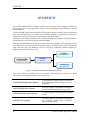
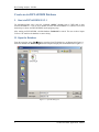
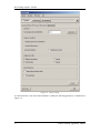
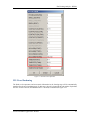
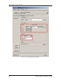
Hot Forming Training Tutorial Version 5.9.2.1 Engineering Technology Associates, Inc. 1133 E. Maple Road, Suite 200 Troy, MI 48083 Tel: +1 (248) 729 3010 Fax: +1 (248) 729 3020 Email: [email protected] Engineering Technology Associates, Inc., ETA, the ETA logo, and eta/DYNAFORM are the registered trademarks of Engineering Technology Associates, Inc. All other trademarks or names are the property of the respective owners. ©1998-2014 Engineering Technology Associates, Inc. All rights reserved. FOREWORD FOREWORD The concepts, methods, and examples presented in this text are for illustrative and educational purposes only, and are not intended to be exhaustive or to apply to any particular engineering problem or design. This material is a compilation of data and figures from many sources. Engineering Technology Associates, Inc. assumes no liability or responsibility to any person or company for direct or indirect damages resulting from the use of any information contained herein. eta/DYNAFORM Application Manual I OVERVIEW OVERVIEW The eta/DYNAFORM software package consists of four programs. These programs represent the pre-processor, solver and post-processor. They are: eta/DYNAFORM, eta/Job Submitter, eta/POST and eta/3DPlayer. eta/DYNAFORM is the pre-processor portion of the software package, which is used to construct the sheet metal forming models. It includes VDA and IGES translators for importing line data and a complete array of tools for altering or constructing line data and meshing it. LS-DYNA is the software package’s solver. eta/DYNAFORM has a complete LS-DYNA interface allowing the user to run LS-DYNA from eta/DYNAFORM. eta/POST and eta/GRAPH are the post-processing portions of the package. These programs are used to post-process the LS-DYNA result files from the analysis. eta/POST creates contour, deformation, FLD, and stress plots and animations with the result files. eta/GRAPH contains functions for graphically interpreting the same results. eta/POST (post-processor) eta/DYNAFORM LS-DYNA (pre-processor) (solver) eta/3DPlayer (post-processor) Figure 1: Components of eta/DYNAFORM solution package. Each of the software components has its own manual which should be referenced for further information on running these programs. These manuals are: eta/DYNAFORM Application Manual A comprehensive training manual for using the eta/DYNAFORM software package for various applications. eta/DYNAFORM User’s Manual A reference guide to the functions contained in the eta/DYNAFORM program (pre-processor). LS-DYNA Keyword User’s Manual A reference guide to the LS-DYNA program (solver). eta/POST User’s Manual A reference guide to the functions contained in the eta/POST program and eta/GRAPH program (post-processor). II eta/DYNAFORM Application Manual TABLE OF CONTENTS TABLE OF CONTENTS FOREWORD................................................................................................................ I OVERVIEW ............................................................................................................... II TABLE OF CONTENTS .......................................................................................... III Hot Forming Analysis - B Pillar ................................................................................. 1 Create an eta/DYNAFORM Database ...................................................................................... 2 I. Start eta/DYNAFORM 5.9.2.1···································································· 2 II. Open the Database ·················································································· 2 HOT FORMING SETUP ........................................................................................................... 4 I. New Hot Forming Setup ··········································································· 4 II. General ······························································································· 5 III. Blank Definition ···················································································· 5 IV. Blank Material and Property Definition ························································· 8 V. Tools Definition ····················································································10 VI. Tools Material Definition ·········································································14 VII. Tools Positioning ··················································································15 VIII. Process Definition ·················································································18 IX. Control Parameters ················································································20 X. Animation ···························································································21 XI. Gravity Loading ····················································································23 XII. Press Hardening ····················································································25 XIII. Submit Job ··························································································27 POST PROCESSING (with eta/POST) ................................................................................... 29 I. Reading the Results File into the Post Processor ··············································29 II. Deformation ························································································30 III. Thinning·····························································································31 IV. View Temperature Distribution ··································································32 MORE ABOUT eta/DYNAFORM 5.9.2.1 ............................................................... 34 CONCLUSION .......................................................................................................... 35 eta/DYNAFORM Application Manual III Hot Forming Analysis - B Pillar 1. Hot Forming Analysis - B Pillar eta/DYNAFORM Application Manual 1 Hot Forming Analysis - B Pillar Create an eta/DYNAFORM Database I. Start eta/DYNAFORM 5.9.2.1 For workstation/Linux users, enter the command “df5921” (default) from a UNIX shell to start eta/DYNAFORM5.9.2.1. For PC users, double click the eta/DYNAFORM5.9.2.1 (DF5921) icon from the desktop or choose eta/DYNAFORM from the program group. After starting eta/DYNAFORM, a default database Untitled.df is created. The user needs to import CAD or CAE model to the database to start working. II. Open the Database From the menu bar, select FileOpen to open the Open File dialog box, as illustrated in Figure 1.1. Select the database file HotForming.df and click Open to display the model illustrated in Figure 1.2. Figure 1.1 2 Open file dialog box eta/DYNAFORM Application Manual Hot Forming Analysis - B Pillar Figure 1.2 eta/DYNAFORM Application Manual Opened Model 3 Hot Forming Analysis - B Pillar HOT FORMING SETUP After finishing the preparation of model, click the Hot Forming from AutoSetup menu to display Hot Forming Setup. Figure 1.3 AutoSetup menu I. New Hot Forming Setup Clicking Hot Forming menu, the New Hot Forming dialog box appears for the user to define the basic setup parameters, as illustrated Figure 1.4. Figure 1.4 4 Sheet Forming Setup dialog box 1. Input blank thickness:1.95 (mm). 2. Select process type: Single Action. 3. Select original die face: Upper &Lower. 4. Click OK to display the Hot Forming interface. eta/DYNAFORM Application Manual Hot Forming Analysis - B Pillar II. General After entering General interface, the program will automatically create three stages: Gravity, Forming and Hardening. As the tool defined in the forming stage is cited in the gravity and hardening stages, the user is allowed to define the blank and tool from the forming stage, as illustrated in Figure 1.5. You do not need to modify any parameters except for changing the Title into Forming. See Figure 1.5. Figure 1.5 General interface III. Blank Definition 1. Enter the Blank interface, and click the Blank tab to display the Blank Definition interface. eta/DYNAFORM Application Manual 5 Hot Forming Analysis - B Pillar 2. Then, click the Define geometry button from Geometry field in the blank definition interface. See Figure 1.6. Figure 1.6 3. The Blank Generator dialog box illustrated in Figure 1.7 is displayed. Figure 1.7 6 Define blank Blank generator dialog box 4. Click the Add Part button to select the BLANK part from the SELECT PART dialog box illustrated in Figure 1.8. 5. After selecting the part, click OK button to return to the Blank Generator dialog box. As illustrated in Figure 1.9, the BLANK part has been added to the list of blank. 6. Click the Exit button to return to the blank definition interface. Now, the color of Blank tab eta/DYNAFORM Application Manual Hot Forming Analysis - B Pillar is changed from RED to BLACK. See Figure 1.10. Figure 1.8 Select Part dialog box eta/DYNAFORM Application Manual Figure 1.9 Blank generator 7 Hot Forming Analysis - B Pillar Figure 1.10 Blank definition interface IV. Blank Material and Property Definition In the hot forming analysis, both the structural material and thermal material need to be defined. The structural materials include MAT 106 and MAT 244. Click the button under the material to display the material dialog box illustrated in Figure 1.11. Click the Import button to import the MAT244 material file blankmat.mat. 8 eta/DYNAFORM Application Manual Hot Forming Analysis - B Pillar Figure 1.11 Structural material definition Note: Users can create the material defined by them by selecting the material type, or edit the selected material. Click the Import button to import the thermal material file blankmat_hot.mat, as illustrated in Figure 1.12. eta/DYNAFORM Application Manual 9 Hot Forming Analysis - B Pillar Figure 1.12 Thermal material definition V. Tools Definition 10 1. Enter Tools interface, and click the red Tools tab to display the Tool Definition interface. 2. icon from the Icon bar, and turn off the BLANK part. Click BLANK button to Click turn off the blank part. 3. Click OK to exit ON/OFF dialog box of the part. The program defines three default tools: die, punch and binder located at the left of tools interface. The user can define the tools one by one. 4. Enter the die interface, and select die located at the left of tools list, then select Define geometry… button to define die, as illustrated in Figure 1.13. 5. The Tool Preparation dialog box is displayed. Click MeshOrganizeDefine tool icon in the preparation dialog box illustrated in Figure 1.14. eta/DYNAFORM Application Manual Hot Forming Analysis - B Pillar Figure 1.13 Die definition Figure 1.14 Preparation 6. The Define Geometry dialog box is displayed. Click the Add part… button, as illustrated in Figure 1.15. 7. Select the DIE button from the popped Select Part interface. See Figure 1.16. eta/DYNAFORM Application Manual 11 Hot Forming Analysis - B Pillar Figure 1.15 8. 12 Tool definition Figure 1.16 Select Part Click OK to return to Define geometry interface, and now the die part has been added to part lists. See Figure 1.17. eta/DYNAFORM Application Manual Hot Forming Analysis - B Pillar Figure 1.17 9. Tool definition Click the Exit button to return to tool definition interface. Now, the die has been defined and the font color of die is changed from RED to BLACK. See Figure 1.18. Figure 1.18 Die definition interface 10. Select punch located at the left side of tools list to display punch definition interface. 11. Finish the definition for punch and binder by referring to Step 5-Step 9. 12. Click the Exit button to exit the Tool Preparation dialog box. eta/DYNAFORM Application Manual 13 Hot Forming Analysis - B Pillar Figure 1.19 Tool definition interface VI. Tools Material Definition In the hot forming analysis, both the structural material and thermal material of the blank, and the thermal material of the tool need to be defined. Dynaform allows the user to same or different materials for the tool. 1. 14 Click the ThermalMat button, as illustrated in Figure 1.20. eta/DYNAFORM Application Manual Hot Forming Analysis - B Pillar Figure 1.20 Thermal material definition of tools 2. Toggle on the Used for all tools option, as illustrated in Figure 1.21. 3. Click the Import button to import the tool material: toolmat_hot.mat. 4. Click the OK button to exit the thermal material dialog box. Figure 1.21 Thermal material dialog box VII. Tools Positioning After defining all tools, the user needs to position the relative position of tools. The tool positioning operation must be carried out each time when the user finishes the tool definition. Otherwise, the user may not obtain correct result. In addition, the tool position is related to the working direction of each tool. Therefore, you need to carefully check the working direction prior to positioning the tools. 1. Click the Positioning button in the Tools tab to display the Positioning dialog box. 2. The program will automatically locate other tools and the blank with binder as the reference position. The tools and the blank will be moved to a new position and the corresponding distance values will display in each edit box, as illustrated in Figure 1.22. Click the Reset button to restore the original position of the blank and tool. Click the On lowers button to position the blank and tool based on the lowers, as illustrated in Figure 1.23. 3. 4. eta/DYNAFORM Application Manual 15 Hot Forming Analysis - B Pillar Figure 1.22 16 Tool positioning dialog box eta/DYNAFORM Application Manual Hot Forming Analysis - B Pillar Figure 1.23 5. Modify datum reference Click icon on the Icon bar to display the relative position of tools and blank(s), as shown in Figure 1.24. eta/DYNAFORM Application Manual 17 Hot Forming Analysis - B Pillar Figure 1.24 6. The relative position of tools and blank after positioning Click OK button to save the current position of tools and blank(s), and return to the Hot Forming interface. Note: In the hot forming, after the user has performed the positioning operation to the tool, the relative position of tools and blanks is displayed on the screen. However, you may follow by clicking the Reset button in the Positioning dialog box to set the tools and blank(s) back to its original position. Now, all Tools have been positioned. The user can set up next process. In Hot Forming application, the definition and positioning of blank(s) and tools and definition of process are not required in strict order. Therefore, you can randomly modify each operation. However, an experiential engineer should have a good habit, so we suggest that the user should set up the tools and blanks step by step. VIII. Process Definition Process definition is helpful to setting up process numbers, time of every process, and condition of every tool and so on. The user can click Process of the main interface, and enter process interface. When defining a new setting, the user only need select a template. Then the program will automatically add some essential processes. To typical program, these processes need not amend or amend a little. In this way, the user can reduce setting time. We select the Single Action template before, so the forming brings two default processes, one is binder process, and the other is draw process. 18 1. Select closing process from the list located at left side of the interface as the current process. Modify the default setting of closing stage, as shown in Figure 1.25(a). 2. Select drawing process from the list located at left side of the interface as the current process. Modify the default setting of drawing stage, as shown in Figure 1.25(b). eta/DYNAFORM Application Manual Hot Forming Analysis - B Pillar a) eta/DYNAFORM Application Manual Closing process interface 19 Hot Forming Analysis - B Pillar b) Drawing process interface Figure 1.25 Process definition IX. Control Parameters In Control interface, use the default parameters suggested by the program. For different model sizes and mesh sizes, we suggest the following operations. Time step size and adaptive steps 1. 20 Click button followed by Time step size (DT2MS), and the program will automatically calculate the time step sizes of the minimum ten elements and the average time step size of all elements. As the method that adopts the minimum time step size has a eta/DYNAFORM Application Manual Hot Forming Analysis - B Pillar good computing stability, but it will take much longer to calculate. Therefore, the user can enter the proper time step size with reference to the above values. Click OK button to accept the calculated time step size for this example, as illustrated in Figure 1.26. 2. Click button behind Thermal Time step (TMAX), and the program will automatically calculate the recommended thermal time step according to the tool movement velocity. Figure 1.26 Control parameters X. Animation Now, the user can display model setting by animation in order to check the movement condition of the tools. eta/DYNAFORM Application Manual 21 Hot Forming Analysis - B Pillar 1. Click PreviewAnimation button from the menu bar, as illustrated in Figure 1.27. Figure 1.27 Animation menu 2. Click the Play button to show the animation of tool movement according to the defined motion curve. 3. The user can select the Individual Frames option from the Animate dialog box illustrated in Figure 1.28 to display the incremental tool movement. Click icon to display the tool movement step by step. Figure 1.28 Animate dialog box 4. It will display the positions of all tools relative to their original states on the screen. See Figure 1.29. 5. Click Exit button to return to the Hot Forming Setup interface. 6. Click SetupSave to save the database. 22 eta/DYNAFORM Application Manual Hot Forming Analysis - B Pillar Figure 1.29 Animation of tool movement XI. Gravity Loading A certain softening occurs to the blank in the hot analysis; therefore, the gravity loading analysis is suggested to conduct generally. It cites the blank and tool of the forming stage in the gravity loading, so the user does not need to re-define the blank and tool. The temperature distribution and the stress-strain information after the gravity loading will automatically transfer to the forming stage. eta/DYNAFORM Application Manual 23 Hot Forming Analysis - B Pillar Figure 1.30 Gravity Loading In Control interface, click the Advanced button to modify the following parameters, as illustrated in Figure 1.31. 24 eta/DYNAFORM Application Manual Hot Forming Analysis - B Pillar Figure 1.31 Thermal control parameter XII. Press Hardening The blank, tool temperature and stress-strain information in the forming stage will be automatically transferred to the press hardening stage. In this stage, the tool is located in the end position. By default, the force for die is 40 tons, and duration time is 5 seconds, as illustrated in Figure 1.32. eta/DYNAFORM Application Manual 25 Hot Forming Analysis - B Pillar Figure 1.32 Press Hardening process definition 26 eta/DYNAFORM Application Manual Hot Forming Analysis - B Pillar Figure 1.33 Press Hardening control parameters XIII. Submit Job After defining all the setup, you may submit jobs of the current setting for calculation. 1. Click JobJob Submitter in the menu bar, as illustrated in Figure 1.34. 2. The program pops up a Job Options dialog box illustrated in Figure 1.35. LS-DYNA double precision solver is adopted for calculation in the hot forming analysis. 3. Click OK button to complete the option setup. eta/DYNAFORM Application Manual 27 Hot Forming Analysis - B Pillar Figure 1.34 Figure 1.35 4. 28 Job menu Job options The current job has already been submitted to the Job submitter for unified management. If there is not any other job in the Job submitter list, the LS-DYNA window is displayed. eta/DYNAFORM Application Manual Hot Forming Analysis - B Pillar POST PROCESSING (with eta/POST) The eta/POST reads and processes all the available data in the d3plot. In addition to the undeformed model data, the d3plot file also contains all result data generated by LS-DYNA (stress, strain, time history data, deformation, etc.). I. Reading the Results File into the Post Processor To execute eta/POST, click PostProcess from eta/DYNAFORM menu bar illustrated in Figure 1.36. The default path for eta/POST is C:\Program Files\ETA\DYNAFORM5.9.2.1. In this directory, you can double click the executable file, EtaPostProcessor.exe to open eta/POST GUI illustrated in Figure 1.37. The eta/POST can also be accessed from the programs listing under the start menu of eta/DYNAFORM. Figure 1.36 Post Process menu Figure 1.37 Post process GUI 1. Select the menu File Open in eta/POST to display the Open dialog box. 2. Select ETA Multiple stage file (*.idx) as the file type, as illustrated in Figure 1.39. 3. Select the HotForming.idx file. 4. Click the Open button to open the calculation result file. eta/DYNAFORM Application Manual 29 Hot Forming Analysis - B Pillar Figure 1.38 File type list 5. The user is allowed to perform the post processing to the result file, and the operation toolbars are illustrated in Figure 1.39. Figure 1.39 Tool bar of eta/POST II. Deformation 1. The default Plot State is Deformation. In the drop-down menu of Frame, choose Single Frame option, as illustrated in Figure 1.40. 30 eta/DYNAFORM Application Manual Hot Forming Analysis - B Pillar Figure 1.40 2. Deformation dialog box Since it is difficult to see the Blank with all of the other tools being displayed, you can hide all the other tools by clicking the icon from Icon bar. 3. In Part Operation dialog, close all the tools except BLANK part. The color of all the closed parts turns to white. 4. Click Exit to exit the operation. 5. The user may also change the displayed model using the view manipulation icons on the Icon bar illustrated in Figure 1.41. Figure 1.41 View manipulation icons III. Thinning 1. Select 2. Select THINNING from the drop-down, as illustrated in Figure 1.42. 3. Click the Play button to animate the thinning contour. icon from the tool bar. eta/DYNAFORM Application Manual 31 Hot Forming Analysis - B Pillar 4. Move the Frame/Second slider to set the animation velocity. 5. Click the Stop button to stop the animation. Figure 1.42 Thickness operation dialog box IV. View Temperature Distribution For the hot forming analysis, the user more concerns about the temperature distribution of the blank and tool. 1. Click 2. Select Temperature from the Contour Plot/Animation drop-down. 3. Select Temperature from the Current Component drop-down, as illustrated in Figure 1.43. 32 icon from the tool bar. eta/DYNAFORM Application Manual Hot Forming Analysis - B Pillar Figure 1.43 Temperature display Note: In addition to the above-mentioned functions, eta/POST also provides the functions such as Major/Minor Strain, FLD, Vector, Circular Grid and Blank Tool Distance. The user can refer to eta/POST User’s Manual for detailed description about these functions. eta/DYNAFORM Application Manual 33 MORE ABOUT eta/DYNAFORM 5.9.2.1 MORE ABOUT eta/DYNAFORM 5.9.2.1 The eta/DYNAFORM 5.9.2.1 configuration file is located under both the installation directory and My Documents directory. Inside the eta/DYNAFORM 5.9.2.1 installation directory, there is a file called dynaformdefault.config. Many key default parameters are included in this file. When the user opens eta/DYNAFORM 5.9.2.1 for the first time, the program will automatically create a file called dynaformdefault.config under My Documents directory. The configuration file locates in the “My Documents” directory of the current user’s PC, for example, C:\Documents and Settings\Andy\My Documents\ETA\Dynaform5.9.2.1 (Windows XP), C:\Users\Andy\My Documents\ETA\Dynaform5.9.2.1 (Windows 7). The user can open this file and change these default parameters, or click OptionEdit Default Config from Menu bar to edit these default parameters in the dialog box. The modified default values in the dialog box will be saved in the configuration file under My Documents directory. The configuration file under My Documents directory will take precedence over the one under the installation directory. For UNIX/Linux users, the dynaformdefault.config file is located under both the installation directory and the user’s home directory (/home/Andy/ETA/Dynaform5.9.2.1). The dynaformdefault.config file located under the installation directory will take precedence over the one located in the user home directory. The default parameters for the hot forming are illustrated in the following figure. Default parameters in hot forming 34 eta/DYNAFORM Application Manual CONCLUSION CONCLUSION This concludes the training guide’s basic overview of eta/DYNAFORM 5.9.2.1. This manual is meant to give you a basic understanding of finite element modeling for forming analysis, as well as displaying the forming results. It is by no means an extensive study of the simulation techniques and capabilities of eta/DYNAFORM. For more detailed study of eta/DYNAFORM, you are urged to attend an eta/DYNAFORM training session. Please refer to the eta/DYNAFORM User’s Manual and the LS-DYNA Keyword User’s Manual for detailed description of individual functions and analysis settings. eta/DYNAFORM Application Manual 35