1
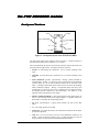
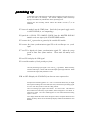
PCM encoding
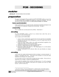
FS - end of frame marker
FS - frame synch
PCM data out
clock periods
LSB at end of frame
time
Figure 3: 5 frames of 4-bit PCM output for zero amplitude input
Knowing:
1. the number of slots per frame is 8
2. the location of the least significant bit is coincident with the end of the frame
3. the binary word length is four bits
4. the first three slots are ‘empty’ (in fact filled with zeros, but these remain
unchanged under all conditions of the 4-bit coding scheme)
then:
T11 identify the binary word in slots 4, 3, 2, and 1.
quantizing levels for 4
4--bit linear
encoding
You will now proceed to determine the quantizing/encoding scheme for the 4-bit
linear case.
T12 remove the ground connection, and connect the output of the VARIABLE DC
module to Vin. Sweep the DC voltage slowly backwards and forwards
over its complete range, and note how the data pattern changes in
discrete jumps.
T13 if you have a WIDEBAND TRUE RMS METER module use this to monitor
the DC amplitude at Vin - otherwise use the oscilloscope (CH1-B).
Adjust Vin to its maximum negative value. Record the DC voltage and
the pattern of the 4-bit binary number.
T14 slowly increase the amplitude of the DC input signal until there is a sudden
change to the PCM output signal format. Record the format of the
new digital word, and the input amplitude at which the change
occurred.
Copyright © 2005 Emona Instruments Pty Ltd
D1-11 - 7