1
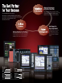
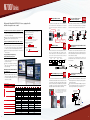
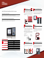
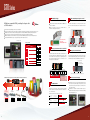
MITSUBISHI CNC
The Best Partner for Your Success
Advanced Technologies
for the Next Generation
With the sophisticated technologies we have developed as a total factory
automation manufacturer, we attain advanced machining control and contribute
This is the MITSUBISHI CNC business philosophy.
to the highest accuracy and productivity of manufacturing worldwide.
All the staffs who are committed to MITSUBISHI CNC business wish to be
MITSUBISHI CNCs change machine tools, machining and manufacturing.
“the best partner for customers aiming at global and future-oriented development”.
We will continue our efforts with the aim that our CNCs
be great help to the customers.
Solid Support for
Day-to-day Comfort
Providing prompt responses, solid technologies
Optimum Solutions for the Future
and user-friendly supports, we continuously
As a global CNC provider as well as the best partner, we provide optimum
in the world so that they choose MITSUBISHI
technologies and supports for the users making a step toward the future.
CNCs again.
improve our after-sales service quality for users
MITSUBISHI CNCs create new values in cooperation with the users.
Contents
Technologies
Solutions
Support
Product Line
M700V Series
M70V Series
E70 Series
P.3-4
P.5-6
P.7-8
P.9-10
P.11-12
P.13-14
P.15-16
User-friendly
C70 Series
User Support Tools
Development Tools
Automation Related Products
Warranty
Global Service Network
P.17-18
P.19-20
P.21-22
P.23
P.24
P.25-26
(Note) The contents of this catalog includes optional specifications. Refer to specification manuals for details.
1
2
Technologies
Technologies
Solutions
for the Next Generation
Support
With the sophisticated technologies we have developed as a total
factory automation manufacturer, we attain advanced machining control
Die/Mold Machining Time
Reduced
and contribute to the highest accuracy and productivity of
High-grade 5-Axis Machining
Control Technology
manufacturing worldwide.
MITSUBISHI CNCs change machine tools, machining and manufacturing.
High-accuracy Machining with
Complete Nano Control
High-quality Machining with
Balanced Accuracy and Speed
Complete nano control enables high-speed and high-accuracy
machining at a maximum fine-segment feed rate of 168kBPM.
(BPM: Block per Minute)
High-speed and High-accuracy Control
High-accuracy machining is realized by controlling each axis
so that the tool center point moves linearly at a commanded
feed rate even if the rotary axis moves in linear interpolation.
Tool Center Point Control
Machining speed attained with 0.1mm-pitch NC program
The complete nano control enables all processing in
nanometers, from NC operation to servo processing.
This advanced machining control technology supports
next-generation ultra-precision machining.
SSS control ensures high machining stability and quality with
virtually no effects resulting from cutting shape or speed.
Smooth surfaces can be achieved even when small steps
exist in a path, and machining time can be reduced by 5 to
30% relative to conventional systems.
M700 Series
(Our Conventional)
13.5m/min
Rotation center
M700V Series
SSS control OFF
16.8m/min
SSS control ON
At the same cutting
rate of F1700.
Y (µm)
504
Y (µm)
1,000
0
502
501
Micron
500
0
High-speed and High-accuracy
Tapping
503
500
500 1,000 1,500 2,000
X (µm)
Taper machining: X:Y=2:1
Machining program
G1 X2. Y1. F9. 43
499
Feed rate: F1700,
Machining time: 1hr 38min 36sec
Feed rate: F1700,
Machining time: 1hr 23min 48sec
Lines left on surface
No lines.
Machining time reduced.
Nanometer
498
497
995 996 997 998 999 1,000 1,001 1,002 1,003 1,004 1,005
X (µm)
Path of tool center point
A high-speed error-compensation function is used for
controlling the spindle and servo, enabling accurate tapping.
At the increased feed
rate of F3400.
OMR-DD Control (Optimum Machine Response Direct Drive)
Interpolation path under nanometer control
Feed rate: F3400,
Machining time: 55min 00sec
<Finish machining condition>
F 1700/3400, S17000, Tool radius: 2mm
No noticeable lines on surface.
Machining time significantly
reduced.
Servo drive unit
Prevention of Interferences
in Machine
When a possibility of interference is detected on a machine
model, the motor decelerates to a stop before interfering.
The part to interfere is displayed in a different color.
Spindle drive unit
3D Machine Interference Check
Directly compensates
synchronization error
Spindle motor
Servo motor
Spindle speed
(r/min)
Spindle speed
(r/min)
4000
3000
2000
1000
0
−1000
4000
3000
2000
1000
0
−1000
Spindle speed
Servo/spindle
synchronization
error
−2000
−3000
−4000
0
0.5
1
1.5
Servo/spindle
−2000
synchronization
−3000 error
−4000
2
2.5
3
3.5
Without OMR-DD control (Sec.)
3
Spindle speed
0
0.5
1
1.5
2
2.5
With OMR-DD control
3
3.5
(Sec.)
Motor decelerates to a stop before interfering.
The part to interfere changes in color.
4
Solutions
Technologies
Solutions
for the Future
Support
As a global CNC provider as well as the best partner, we provide
Energy Savings
optimum technologies and supports for the users making a step
toward the future.
MITSUBISHI CNCs create new values in cooperation with the users.
Original Screen Design Environment
Drive units
Application of the power regeneration system which allows
energy generated during deceleration to be efficiently used
as a power supply. Use of low-loss power devices enables
reductions in loss of power.
Spindle motors/Servo motors
Energy loss of spindle motors during high-speed operation
has been substantially reduced. Drive current of servo
motors has also been reduced by downsizing the motors
while increasing the torque.
Spindle motor
Energy flow when motor is decelerating
Energy loss during continuous rated load operation
When motor is decelerating, energy in the motor is fed back to the power supply.
MDS-D2/DH2-CV
Converter
circuit
3-phase AC
power supply
6
MDS-D2/DH2-Vx
MDS-D2/DH2-SPx
Energy loss [kW]
Well-developed screen design tools help bring out the uniqueness of CNCs.
NC Designer, which helps create original screens easily, enables users to add unique customized screens that meet machine
tool characteristics.
Two types of designing methods are available: a programming-free method in which automatic programming is carried out upon
laying out switches, buttons and data display frames, etc. and a programming method that enables higher-level processing.
Inverter
circuit
Regeneration
inverter
circuit
Spindle motor
Servo motor
Current
4
Cut by 56%
3
5.2
2
2.3
1
Energy flow during deceleration
[Programming-free]
When rated output is 17.6kW at 15,000r/min
5
0
Our conventional
series
Motor current
High-efficiency
spindle motor
Servo motor
Current at stall torque
Macro data
0
Project files
Rated output: 2.0kW
Time
Reduced by
40%
Speed
Add
NC Designer
Motor speed
22.4
13.4
CNC display
Source codes
Source codes
(Arms)
Compile and link
[Programming method]
Time
Unique codes
Manufacturing Support Software
We provide optimal solutions for manufacturing sites by combining various software.
*Contact us for the details
of each software.
Our conventional
series
New series
Mitsubishi Factory Automation Solutions
Production management
Facility maintenance
Quality control
Our cultivated Factory Automation technologies and
experience contribute to offer the best suited systems for users.
Our FA solutions support high and low hierarchy components,
a network and even applications that control the components
and network required for a manufacturing floor.
Machining network system
Information
technologies
CAD/CAM system
Production management system
Optimized
Waste eliminated
MELQIC
inspection unit
Production management system
CAD/CAM system
GOT1000
MES
interface
Mechatronics
technologies
Machining network system
Electron beam machine
Control
technologies
Laser
EDM
Higher performance
Shorter machining time
NC
NC
NC
NC
MITSUBISHI CNC
M700V/M70V
PLC
Motion
controller
Robot
MITSUBISHI CNC
E70
MITSUBISHI CNC
C70
Drive
technologies
Distribution
technologies
Data transfer tool
NC Explorer
Remote monitoring tool
NC Monitor
Simple programming tool
NAVI MILL on PC/NAVI LATHE on PC
Power measuring
Energy measuring
module
MDU
module
Electric type
circuit breaker
indicator
Higher efficiency
Energy saved
AC servo
Inverter
Robot
Mitsubishi FA product groups
5
6
Technologies
Solutions
Support
for the Day-to-day Comfort
Support
Providing prompt responses, solid technologies and
After-sales Service
Displays in 17 Languages
user-friendly supports, we continuously improve our after-sales
service quality for users in the world so that they choose
MITSUBISHI CNCs again.
Global Service & Support Network
We provide satisfying after-sales services worldwide, aiming to be your best partner.
Maintenance service
Our service centers boasting high-quality customer service
system are located in various regions around the world to
provide secured and
reliable services for the
users. We offer wide
range of services such
as giving prompt and
precise advices and
suggestions, and onsite repairs, etc.
Supports 17 languages.
Supported languages
Japanese
English
German
Italian
French
Spanish
Chinese (traditional)
Chinese (simplified)
Korean
Portuguese
Hungarian
Dutch
Swedish
Turkish
Polish
Russian
Czech
Part supply
As each service center keeps maintenance parts in stock, the
down time after a failure can be minimized. We are making
our efforts to provide
utmost services that
allow users to use their
CNC machine tools
more securely.
High-quality
Our top priority is to provide users with high-performance and
high-quality products. We are making the best efforts to improve quality and reliability in every process from planning,
development, designing and manufacturing through operation
after delivery.
One-year maintenance contract
We provide maintenance services after expiration of warranty period in one-year units. Should there be any failure,
our engineer in the closest service center will be at your support immediately.
Training
Nagoya Works
Korean FA Center
Shanghai FA Center
Taiwan FA Center
Thailand FA Center
India FA Center
ASEAN FA Center
European FA Center
North American FA Center
We provide trainings on both basic and advanced operations
using actual machines. Individually tailored training programs
and on-site lessons are also available.
Please contact us for details.
FA Development Center
Nagoya Works
FA Communication Center
East Japan Mechatronics
Solution Center
West Japan Mechatronics
Solution Center
We have established FA Centers that manage service centers and service satellites in each area to enhance our service
quality by providing trainings for engineers and enhancing service parts and repair facilities.
7
8
Product Line
Drive Units
Advanced product lines take your machine to the next level
High-grade Mitsubishi CNC M700V Series,
Equipped with Advanced Complete Nano Control
The latest RISC-CPU is installed to achieve
advanced complete nano control
High-accuracy machining with complete nano
control
Easy operability that significantly reduces machining setup time
High-performance Servo/Spindle Drive Units
MDS-D2/DH2 Series
Multi-hybrid Drive Units MDS-DM2 Series
A line of high-performance multi-hybrid drive
units are available. The multi-hybrid drive unit
drives a maximum of three servo axes and one
spindle, supporting the ownsizing of units and offering technical advantages.
A power regeneration system that efficiently uses
energy during deceleration as power contributes
to highly-frequent acceleration/deceleration and
energy savings.
STO (safe torque off) is now available. (Note)
With the fastest current control cycle, basic performance is drastically enhanced
(high-gain control). A combination of high-speed servo motor and highaccuracy detector helps enhance overall drive performance.
A high-efficiency fin and low-loss power module have enabled unit downsizing. A
line of drive units driving a maximum of two spindles is available, contributing to a
reduction in control panel size.
STO (safe torque off) is now available. (Note)
All-in-one compact drive units MDS-DJ Series
Ultra-compact drive units with built-in power supplies contribute to reducing control panel size. The 2-axis type is added for further downsizing.
High-speed optical communication enables a shorter position interpolation cycle and direct
communication between drives, promoting further high-speed and high-accuracy machining.
A high-efficiency fin and low-loss power module have enabled unit downsizing,
which also leads to a reduction in control panel size.
STO (safe torque off) is now available. (Note)
(Note) Please contact us for availability of STO as a whole system.
Servo Motors
M700VW Series
(equipped with Windows® XPe)
Medium-inertia Motor HF Series
M700VS Series
Global Standard Mitsubishi CNC M70V Series, Pursuing High Speed and Accuracy
Enhanced machining accuracy and reduced
tact time
Easy and advanced operation contributing to
setup time reduction
Compact size
Low-inertia Motor HF-KP Series
High-inertia machine accuracy is ensured. Suitable
for machines requiring quick acceleration.
Range:
0.5 to 9 [kW]
Maximum speed: 4,000 or 5,000 [r/min]
Supports three types of detectors with a resolution
of 260,000, 1 million or 16 million p/rev.
Suitable for an auxiliary axis that require
high-speed positioning
Range:
0.1 to 0.75[kW]
Maximum speed: 6,000 [r/min]
Supports a detector with a resolution of
260,000p/rev.
Linear Servo Motor LM-F Series
Direct Drive Servo Motor TM-RB Series
Use in clean environments is possible since no ball screws are
used and therefore contamination from grease is not an issue.
Elimination of transmission mechanisms which include backlash,
enables smooth and quiet operation even at high speeds.
Dimensions:
Length:
290 to 1,010 [mm]
Width:
120 to 240 [mm]
High-torque direct-drive combined motor with a
high-gain control system provides quick acceleration
and positioning, which makes rotation smoother.
Suitable for a rotary axis that drives a table or spindle
head.
Range:
Maximum torque: 36 to 1,280 [N·m]
Spindle Motors
Simple CNC E70 Series, Offering Easy Operability and High Cost Performance
High-performance New Type Spindle Motor SJ-D Series
Motor energy loss has been significantly reduced
by optimizing the magnetic circuit.
Product line:
Normal
SJ-D Series
3.7 to 11 [kW]
Compact & light
SJ-DJ Series
5.5 to 15 [kW]
Simple operations free operators from burden
With the latest hardware installed, this CNC
realizes high cost performance
Low-inertia, High-speed New Type Spindle Motor SJ-DL Series
iQ Platform Compatible CNC C70 Series Incorporated with
Mitsubishi's State-of-the-Art Technologies
Compatible with the Mitsubishi FA integrated
solution, “iQ Platform”
High-performance CNC integrated with highspeed PLC offers high-speed control to reduce
cycle time
A wide variety of FA products helps construct
flexible lines
Tapping machine-dedicated spindle motors have
joined the new spindle motor line SJ-D Series in an
effort to speed up drilling and tapping.
The low-inertia reduces acceleration/deceleration
time, resulting in higher productivity.
Product line:
Low-inertia SJ-DL Series
0.75 to 7.5 [kW]
Built-in Spindle Motor SJ-BG Series
The optimized electrical design increases
the continuous rated torque per unit
volume compared to our conventional
model, contributing to downsizing of the
spindle unit.
The mold with cooling jacket is available
as an optional feature.
High-performance Spindle Motor SJ-V Series
A vast range of spindle motors is available, all ready to
support diversified machine tool needs.
Product line:
Normal
SJ-V Series
0.75 to 55 [kW]
Wide-range constant output
SJ-V Series
5.5 to 18.5 [kW]
High-speed
SJ-V-Z Series
2.2 to 22 [kW]
Hollow-shaft
SJ-VS Series
5.5 to 18.5 [kW]
Low-inertia, High-speed Spindle Motor SJ-VL Series
The spindle dedicated to tapping machines requiring
faster drilling and tapping.
The low-inertia reduces acceleration/deceleration time,
resulting in higher productivity.
Product line:
Low-inertia normal
SJ-VL Series
3.0 to 11 [kW]
Low-inertia hollow shaft SJ-VLS Series
3.7 to 11 [kW]
Tool Spindle Motor HF-KP/HF-SP Series
Taking advantage of the characteristics of a servo motor such as smallness and
high-output, this motor serves as a compact and high-output spindle motor which is
capable of high-speed rotation (6,000r/min). This motor contributes to downsizing
of spindles, such as the rotary tool spindle.
Product line:
Small capacity
HF-KP Series 0.4 to 0.9 [kW]
Medium capacity HF-SP Series
2.2 to 4 [kW]
*Customized screen
9
10
M700V Series
Tool Center Point Control
Complete Nano Control
(Machining Center System)
*M750VS,M750VW only
High-grade Mitsubishi CNC M700V Series, equipped with
advanced complete nano control
Latest RISC-CPU achieves Advanced Complete Nano Control
All operations from program values to servo commands are
done in nanometer units. Interpolation is at the nano-unit
level even when program commands are in micrometer
units.
High-speed architecture
M700V Series' numerical processing performance and PLC
processing performance have been significantly improved from
those of our conventional M700 Series.
The latest RISC-CPU and high-speed optical servo network are
installed, achieving high-speed and high-accuracy control, nano
control and 5-axis machining
Functions can be easily expanded by adding an expansion unit
Ultrahigh-speed PLC engine reduces cycle time
<Tool tilt type>
Rotation center
M700 Series
High-accuracy detector:
16million p/rev
High-gain control II
1
M700 Series
M700V Series
10 steps/µs
100 steps/µs
M700V Series
(Lathe System)
Optimum Feed Forward
Built-in PLC Basic Instruction Processing Performance
M700 Series
Guide Bushing Spindle Synchronization Control
OMR-FF Control
2
Unlike conventional control, which simply matches the motor
path to the commands, OMR control calculates the machine's status based on a model and applies correction to
motor control in order to match not the motor position, but
the machine tool position to the commands.
Command
NC
Current
Servo
Motor-end
Motor
Machine-end
Machine
Machining
Bar feeder
Motor
Ball screw
Table
SSS Control(Machining Center System)
Super Smooth Surface
Main Specifications
Machining center system
Number of control axes
Maximum number of NC axes (in total for all the part systems)
8
M730VS
Maximum number of spindles
4
Maximum number of PLC axes
6
Maximum number of PLC indexing axes
Maximum number of NC axes per part system
16
12
16
12
16
8
4
6
Least control increment
Maximum PLC program capacity
Display
Keyboard
Windows ® XPe
MITSUBISHI CNC machine operation panel
M730VW
12
16
16
12
16
4
6
6
8
2
4
6
6
6
4
8
4
4
8
2
8
2
4
—
Available
Available
Available
Available
Available
—
—
Available
Available
0.1µm
1nm
0.1µm
1nm
1nm
0.1µm
1nm
1nm
1nm
1nm
2,000kB
(5,120m)
2,000kB
(5,120m)
2,000kB
(5,120m)
2,000kB
(5,120m)
128,000 steps
128,000 steps
128,000 steps
128,000 steps
8.4-type/10.4-type/10.4-type touch panel/15-type (selectable)
10.4-type/10.4-type touch panel/15-type/15-type touch panel (selectable)
Sheet keys/clear keys (selectable)
Clear keys
—
Available
Compatible
Compatible
Control Axis Superimposition
(Lathe System)
This function enables machining using a certain part system
simultaneously with that of another part system by superimposing their movements.
This is effective when machining in multiple part systems is
ex-ecuted simultaneously. It allows for an axis to shift its coordi-nate system relative to the system using the axis.
X1
Workpiece travel command
for the 1st part system
8
6
—
1nm
SSS control is now available for the most basic function of fiveaxis simultaneous interpolation control, tool center point control.
It compensates uneven paths output from CAM to smoothly
joint the tool center points’ path. In addition, rotary axis pre-filter
is available to move the rotary axis smoothly, which achieves
high-grade cutting in five-axis simultaneous machining.
Guide bushing
(G/B spindle)
Collet chuck
(Reference spindle)
SSS control realizes high-quality machining compared
to the conventional high-speed high-accuracy mode
that leaves scratches on the surface as a result of
errors in CAD/CAM shapes and paths.
6
4
8
M750VW
16
Available
0.1µm
Maximum program capacity
M720VW
4
6
4
2
Lathe system
M750VW
6
4
8
8
Hard disk mode
M730VW
6
6
Front IC card mode
M720VW
12
6
CF card in control unit mode
Machining center system
M750VS
M730VS
16
4
Maximum number of part systems
Least command increment
Lathe system
M720VS
M750VS
4
Maximum number of simultaneous contour control axes
Bar feeder
Guide
Since Windows®XPe is installed in M720VW,
M730VW and M750VW, they facilitate developing such as MTB’s original CAM function and data managing function that can
enhance the operability
12
Machining
result
This function is for a machine with a spindle motor to rotate a
guide bushing: This function allows the guide bushing spindle motor (G/B spindle) to synchronize with a reference spindle motor (Reference spindle).
The position error compensation function reduces the
spindle’s vibration due to the workpiece’s torsion, and the
motor’s overload.
Calculation
OMR-FF Control
Windows ®XPe-based Model Added to
the Product Line
Maximum number of control axes (NC axes + spindles + PLC axes)
Rotation center
Rotation center
Path of the tool center point
User Macro Processing Performance
NC screen design has been renewed to
strongly support operations from machining setup to monitoring
The NC screen displays machining program check and machining states visually
by using 3D display
M720VS
Path of the tool
center point
168kBPM (Note 1)
(Note 1) BPM is the number of machining program blocks processed per minute.
(Note 2) M720VS’s machining program processing speed is 67.5kBPM.
Easy Operability that Significantly
Reduces Machining Setup Time
Model name
<Compound type>
Path of the tool
center point
135kBPM (Note 1)
M700V Series (Note 2)
Combination of “complete nano control” that processes everything from NC operation to servo control processing in nanometers, a state-of-the-art technology “SSS control” and “OMR control” makes it possible to achieve ultrahigh-quality machining
High-speed and high-accuracy machining at 168k blocks per
minute is possible
Specifications
<Table tilt type>
Table
High-speed
optical network
Machining Program Processing Speed
High-accuracy Machining with Complete Nano Control
Drive unit
MDS-D2/DH2
M700V Series
High-accuracy machining is realized by controlling each axis
so that the tool center point moves linearly at a commanded
feed rate even if the rotary axis moves in linear interpolation.
Z1
Tool travel
commandfor
the 2nd part
systemThe
SSS control
ON
Uneven paths are
compensated
high-speed high-accuracy mode(G61.1)
Z2
X2
The tool moves so as to keep
its relative position with the workpiece2ndpart
SSS control
* Maximum specifications including optional specifications are listed.
11
12
M70V Series
Rapid Traverse Constant Inclination High
Multi-step Acceleration/Deceleration Function Speed
(Machining Center System)
Global standard Mitsubishi CNC pursuing high speed and accuracy
*1st part system only
Rapid traverse acceleration/deceleration is performed
according to the motor’s torque characteristics.
As the motor’s characteristics can be utilized optimally,
positioning time is reduced, and cycle time is improved.
Enhanced Machining Accuracy and Reduced Tact Time
The minimum command unit of 0.1µm and minimum internal interpolation unit of 1nm allow highly accurate and smooth machining
High-speed error compensation function is incorporated in spindle and servo controls, which enables high-speed and highaccuracy tapping, etc
The high-speed PLC engine enhances the operation speed, contributing to cycle time reduction
Hobbing (Lathe System)
*TypeA only
Performance
Rapid traverse constant inclination
multi-step acceleration/deceleration
G code format is available for hobbing.
A spur gear can be machined by synchronously rotating
the hob axis and the workpiece axis in a constant ratio. A
heli-cal gear can be machined by compensating the workpiece axis according to the gear torsion angle for the Z
axis movement.
Speed
Rapid traverse constant inclination
acceleration/deceleration
Easy and Advanced Operation Contributing to Setup Time Reduction
This CNC is equipped with pop-up screens that prevent operators from being bothered with screen hierarchy, and guiding function that displays guidance on operations, programs and alarms
Ethernet interface is installed as standard; thus, program management can be easily realized
A compact flash installed in front of the display allows storing of large-capacity NC programs and easy management of maintenance data
Simple programming functions NAVI MILL and NAVI LATHE are installed
Hob axis
Reduced by 30%
Workpiece axis
Time
3D solid program check (Machining Center System)
*TypeA only
Mixed Control(cross axis control)
(Lathe System)
*TypeA only
Compact Size Achieved
Unit dimensions have been downsized by integrating a display with CNC control part, contributing to downsizing of control panel
High visibility TFT color LCD is used. 8.4-type and 10.4-type displays are available
The added 3D solid model check function allows more
realistic cutting check.
The control axes of each part system can be exchanged
using a program command. This enables the axis defined as
the axis of the 1st part system to be operated as the axis of
the 2nd part system.
Switching C1 axis control from the 1st part system to the 2nd part system
1st part system
1st part system
X1
X1
Z1
C1
C1
X2
Z2
2nd part system
SSS Control(Machining Center System)
Super Smooth Surface
Main Specifications
Machining center system
Model name
Number of
control axes
Lathe system
M70V TypeB
M70V TypeA
M70V TypeB
M70V TypeA
Maximum number of control axes (NC axes + PLC axes + spindle)
9
11
9
11
Maximum number of NC axes (in total for all the part systems)
5
8
5
9
Maximum number of spindles
2
2
3
4
Maximum number of PLC axes
6
6
6
6
Maximum number of simultaneous contour control axes
4
4
4
4
1
2
1
2
Specifications
Maximum number of part systems
Maximum program capacity
Maximum PLC program capacity
Display
Keyboard
500kB [1,280m]
20,000 steps
2,000kB [5,120m]
32,000 steps
20,000 steps
32,000 steps
Path A
Without SSS control
Compatible
Actual cutting path
Path B
Sheet keys/clear keys (selectable)
Scratches on
machined surface
Z
C
Path A
Smooth
command path
Path B
Tiny difference in level
13
Smooth command path
This function converts the commands programmed for the
orthogonal coordinate axes into linear axis movements
(tool movements) and rotary axis movements (workpiece
rotation) to control the contours.
It is useful for tasks such as cutting linear cutouts on the
outside diameter of the workpiece and grinding camshafts.
X
Tiny difference in level
8.4-type/10.4-type/10.4-type touch panel (selectable)
NC Designer
2nd part system
Y
500kB [1,280m]
MITSUBISHI CNC machine operation panel
* Maximum specifications including optional specifications are listed.
Without SSS control
2,000kB [5,120m]
HMI customization function
Z2
Polar Coordinate Interpolation(Lathe System)
1nm
Least control increment
X2
*TypeA only
By judging shapes in large from commanded paths, unnecessary deceleration is reduced even when fine steps exist; thereby, realizing smooth and deviation free die-mold machining.
Machining time can be shorter by 5 to 30% relative to our
conventional system, especially more effective at a higher
(Note) Additional hardware is required.
feed rate.
0.1µm
Least command increment
Z1
SSS control
Path A
Smooth command path
With SSS control
Actual cutting path
Tiny difference in level
Path B
Interpolation for
smooth step cutting
14
E70 Series
Nano Control
Simple CNC Offering Easy Operability and High Cost Performance
Memory Card/USB Memory Interface
Interpolation calculation accuracy improved
Simple operations free operators from burden
This CNC has the same screen structure as of M700V and M70V Series, allowing easy operations.
Switching between milling and lathe systems is accomplished simply by changing the parameter.
Various support tools help reduce initial setup time including the time for developing ladder programs and customized screens.
Even with one-micron-unit commands in the machining
program, interpolation is in nanometer units. As the calculation
accuracy of a block intersection is improved, lines on the
surface is finer.
A compact flash memory card (CF card) /USB memory
interface is located on the front of the display. In using CF
card, the card slot can be completely covered by a lid so as
to prevent foreign materials from entering (IP67).
Y(µm)
540
530
520
With the latest hardware installed, this CNC realizes high cost performance
510
Y(µm)
CNC control part integrated with a display provides compact size and high cost performance.
Ethernet interface is installed as standard; thus, program management can be easily realized.
Compatible with analog output, this CNC allows a spindle motor to be driven by an inverter.
1-micrometer
500
1,000
1-nanometer
490
480
500
470
950 960 970 980 990 1,000 1,010 1,020 1,030 1,040 1,050
X(µm)
0
0
500
1,000 1,500 2,000
X(µm)
PLC Axis
Inclined Axis Control (Lathe System)
Even when the control axes configuring a machine
aremounted at an angle other than 90 degrees, this
function enables it to be programmed and controlled in
the same way as with an orthogonal axis.
The inclination angle is set using a parameter, and axes
are controlled using the movement amounts of the axes
which are obtained through conversion and compensation
using this angle.
<Example of use>
When the X axis serves as the basic
axis and the Y axis serves as the
inclined axis
X: Actual X axis
Y: Actual Y axis
y: Programmed Y axis
θ: Inclination angle
X
Yp×tanθ
Indexing function
By setting the number of stations required for the application, the drive automatically sets up equal intervals between
each station. Positioning of the axis is only possible by commanding the station number.
1
24
23
2
3
4
Indexing position
22
9
21
Xa
5
6
7
8
Decelerator
10
11
12
13
20
Yp
θ
Main Specifications
Model name
Specifications
Number of
control axes
Servo motor
y
θ
Milling system
Maximum number of control axes (NC axes + PLC axes + spindle)
6
6
Maximum number of NC axes (in total for all the part systems)
3
3
Maximum number of spindles
1
2
Maximum number of PLC axes
2
2
Maximum number of simultaneous contour control axes
3
3
Maximum number of part systems
Least command increment
Least control increment
Maximum program capacity
Maximum PLC program capacity
Display
Keyboard
Yp/cosθ
Lathe system
1
19
Ya
18
14
17
16
15
Indexing function with magazine axis
Y
Spindle/C-axis Control
MITSUBISHI CNC Machine Operation Panel
1
0.1µm
1nm
230kB [600m]
8,000 steps
The spindle's constant position loop control has eliminated
the zero point return time when switching from the spindle to
C-axis.
8.4-type
Sheet keys
HMI customization function
NC Designer
MITSUBISHI CNC machine operation panel
Compatible
Speed
PLC program samples have been prepared for the basic key
layout, enabling the creation of suitable PLC programs for your
machine simply by adding interface components with machine. Refer to the product brochure for details.
Speed
* Maximum specifications including optional specifications are listed.
Shortened
Zero
point return
C-axis
positioning
<Our conventional series>
C-axis
positioning
Time
<E70 series>
Time
Example when combined with an 8.4-type display
15
16
User-friendly
for M700V Series & M70V Series & E70 Series
Operation Support
Human Machine Interface allowing easier and more visible use
Manual/Automatic backup function
HMI for Easier and More Visible Use
Screen structure linking to the operation processes
Operation processes are divided into three steps, “Monitor”,
“Setup” and “Edit”, and necessary information is aggregated
into three screens. These screens can be displayed by touching a single button on the keyboard.
(HMI:Human Machine Interface)
Pop-up screens
Batch-backup of the NC data into the memory card/USB
memory inserted in the front interface of the display is possible. For the built-in hard disk type M700VW Series,
backup in the hard disk is also possible.
Data is automatically backed-up at a certain interval set by
the parameter.
Program input error warning function
The added 3D solid model check function allows more realistic cutting check.*1
This function helps an operator to input and check programs.
Errors are indicated when a decimal point is omitted.*2
Tabs allow the user to select necessary operations from the
operation menu, and pop-up screens allow the user to
access desired information while the original screen remains
displayed. For displays with a touch panel, a keyboard can be
displayed on the screen.
Integration of program check
and editing functions
Decimal point omitted: A decimal
point has been left out of the
address data
Tab selection
Program check based on a 3D solid model
Large amount of information aggregated
into one screen
*1 Available with M700V Series, M70V TypeA (M System) only.
*2 Available with M700V Series only.
Manual/automatic backup function
Machining conditions
are displayed visually
Edit screen
Guidance function
Menu list
By pressing the help button, guidance (operation procedure
/parameter descriptions/alarm descriptions/G code format)
regarding the currently displayed screen will be shown.
Icon menu displays
screen images
Menu list buttons are newly introduced. With these buttons,
the screen desired for display can be called up directly.
The selected screen’s function outline is also displayed.
Counter display is
automatically enlarged
in the manual mode
Pop-up window
to avoid screen
switching
Visible hierarchy
with two-layer
menu display
Keyboard is displayed in the pop-up window
(for touch-panel displays)
Monitor screen
Shortcut icons to each screen
Setup screen
2-part system display
The Monitor screen of the 2nd part system can be displayed
together with the 1st part system. Switching screens is not
necessary.
Menu customization function
Menu keys on the bottom of the screen can be freely arranged. Frequently used menu keys can be put together on
the first page.
Outline of the selected
function appears
Simple Programming Functions with Simple Machining Menu
NAVI MILL (Machining center system) / NAVI LATHE (Lathe system)
* M700V Series, M70V Series only
Programs are automatically created for each process when an operator selects machining process and inputs data on screen.
A tool path can be graphically drawn for the program check.
This function also supports inclined surface machining.
Guidance image area
An operator sets the
shape of the inclined
surface to machine
2-part system display
17
NAVI MILL (Machining center system)
Machining
surface view
NAVI LATHE (Lathe system)
18
C70 Series
Building Block Type
iQ Platform-compatible CNC, providing the largest effect
on TCO reduction
Multi-axis, Multi-part System Control
Variety of network modules for Mitsubishi PLC MELSEC-Q
Series are available.
Motion controllers and robots are compatible with iQ
Platform, enabling system expansion.
A CNC structured in building block method on iQ Platform
Compact and high-speed CNC CPU module "Q173NCCPU" equipped with the multi-axis and multi-part system control
Ultrahigh-speed connection between ultrahigh-speed PLC CPU module MELSEC QnUD (H) CPU and CNC CPU
Variety of modules for power supply, input/output interface, network and measurement are available
"Mitsubishi Graphic Operation Terminal", an easily customizable HMI with high performance and multiple functions
Compatible with MELSOFT, easy-to-use engineering tools with multiple functions
<CNC CPU1>
Slot-in structure
for quick
attach/detachment
Main Specifications
Spindle motor
Servo motor
Spindle motor
Machining Lathe system
center system
Number of basic control axes (NC axes)
3
2
Maximum number of control axes (NC axes + spindles + PLC axes)
16
16
Maximum number of NC axes (total for part systems)
16
16
Maximum number of spindles
7
4
Maximum number of PLC axes
8
8
Number of simultaneous contouring control axes
4
4
Maximum number of NC axes in a part system
8
8
1
1
7
3
Standard number of part systems
Number of
control
part systems Maximum number of part systems
Ultrahigh-speed network between CNC CPUs and PLC CPUs
Safety Observation Function
Select from among
30/40/60/100/130/260
Program capacity [k steps]
PLC
function
Servo motor
Drive unit
C70
Specifications
Number
of control
axes
<CNC CPU2>
Drive unit
*Customized screen image
Model name
One CNC CPU module up to 7 part systems and 16 axes.
Up to two CNC CPU modules can be installed on iQ Platform.
For data transfer between CNC CPUs and PLC CPUs, we
have newly developed a dedicated high-speed bus. Data
are transferred at a high-speed cycle (0.88ms) between
the high-speed shared memories of each CPU, so each
CPU speed can be fully utilized.
This function enables safety signal comparison, speed observation and duplexed emergency stop. This function complies
with the European safety standard EN ISO 13849-1 PL d.
PLC CPU (Q0×UD×CPU)
CNC CPU (Q173NCCPU)
124/252
Maximum number of files to store
Safety signal module (Q173SXY)
4,096
Number of input/output points
PLC CPU
CNC CPU
CNC CPU
High-speed
Shared
memory
shared
memory
between CPUs
High-speed
Shared
memory
shared
memory
between CPUs
High-speed
Shared
memory
shared
memory
between CPUs
I/O network
Shared
memory
Shared
memory
Comparison of safety signals
Speed monitoring
Dual emergency stop
MELSEC Q bus
iQ Platform makes it possible to structure optimum controllers for various lines.
High-speed bus between multiple CPUs
Safety and
Energy-savings
Maintenance
Manufacturing
Technologies
Advancement
New Model Q PLC
Design and
Development
Reliability
Engine
machining line
PLC
CNC
HMI
CNC Servo Drive
CNC Spindle Drive
Engine
assembly line
PLC
Motion Controller
HMI
Servo Drive
Welding line
PLC
HMI
Servo Drive
Vehicle body
assembling line
PLC
HMI
Servo Drive
Data are transferred at a
high-speed cycle (0.88ms)
between the high-speed
shared memories of each CPU.
Continuity
Sequence processing time is widely accelerated, including
3.5 times faster basic instruction performance compared to
our conventional one.
Reduced scan time also reduces the tact time.
Basic command
performance
New model Q PLC
Floating-point
arithmetic
performance
New model Q PLC
PCMIX value
GOT 1000 Series Displays
Customized screens can be easily developed with the GOT
screen creation tool (GT Designer). It is possible to operate
a machine via a touch panel instead of a conventional machine operation panel.
NC Monitor is installed in SVGA and XGA models as
standard, which enables setting of each NC data and editing
of machining programs, etc.
Approx. 3.5 times
Conventional PLC
Approx. 13 times
Conventional PLC
New model Q PLC
Approx. 6 times
Conventional PLC
*Customized screen image
19
20
User Support Tools/Development Tools
User Support Tools Provide an Improved CNC Environment
Rich Development Tools Help Bring out the Uniqueness of CNCs
NC Designer
NC Trainer/NC Trainer plus
Remote Monitoring Tool
Data Transfer Tool
Servo Adjustment
Support Tool
Parameter Setup
Support Tool
M700V M70V
E70
MITSUBISHI CNC Training Tool
NC Trainer is an application for operating the screens of MITSUBISHI CNC M700V/M70V/E70 Series and machining programs. This application can be used for learning operating
CNC and checking the operations of the machining programs.
NC Trainer plus can also be used for checking the PLC program and custom screens.
Ethernet
M700V M70V
E70
Screen Design Tool
NC Analyzer
M700V M70V
E70
C70
Servo Adjustment Support Tool
By laying out ready-made standard parts, you can easily
create original screens without programming.
Using the C language source generation function of NC Designer, customized functions can be added by programming in
C language. (Dedicated development environment necessary)
Parts displayed on NC
(example)
Servo parameters can be automatically adjusted by activating
the motor using machining programs for adjustment or vibration
signals, and measuring/analyzing the machine characteristics.
<Main functions>
Bode diagram measurement display, speed loop gain adjustment, position loop gain
adjustment, notch filter setting, acceleration/deceleration time constant adjustment,
circularity adjustment and servo waveform measurement
Edit on a personal computer
Insert
Insert
PCMCIA
card
CF card
M700V/M70V/E70 Series
Ethernet
communication
M700VW Series
Memory card
NC Analyzer
CF card
NC Trainer
NC Trainer plus
NC Designer
NC Monitor M700V
NC Explorer
M700V M70V
E70
NC Maintainer
M700VW
Data Transfer Tool
By connecting the NC and host personal computer via Ethernet, data such as machining programs can easily be shared.
This tool is free of charge. Please contact us.
NC1
NC2
A software tool for a personal computer to carry out maintenance (such as parameter setting, NC diagnosis and PLC program diagnosis) of MITSUBISHI CNC on customer’s display.
M70V
E70
/Remote Monitor Tool
C70
Remote Monitoring Tool
NC Configurator2
M700V M70V
E70
C70
Parameter Setup Support Tool
An identical NC display screen can be displayed on a personal computer. By connecting a personal computer to the
NC unit when necessary, various data can be checked and
set using the same HMI as the standard NC screen.
Remote Monitor Tool (C70) is free of charge. please contact us.
The NC data file necessary for NC control and machine operation (such as parameters, tool data and common variables)
can be edited on a personal computer.
Please contact us to purchase a full function version. (A limited
function version is also available free of charge.)
NC3
Ethernet
communication
Ethernet
communication
Ethernet
communication
Ethernet
NC4
NC5
NC6
Customer’s display
Control unit
NC Configurator2
NC Monitor (M700V, M70V,E70)
Servo Selection Tool
M700V M70V
E70
C70
Diagnosis screen
Maintenance screen
PLC program diagnosis screen
* An operation check is required in combination with software installed on the display.
By selecting the machine configuration model and inputting the machine specifications, the optimal
servo motor meeting specifications
can be selected. Other selection
functions which fully support drive
system selection are also available.
This tool is free of charge. Please
contact us.
E70
C70
The MELSEC programming tool, offering a wide array of
functions and easy use, allows for convenient program
design and debugging. Linking with a simulator or other utility allows for the efficient creation of desired programs.
When the machine model and input
specifications are selected,
the selection result for the motor will
be displayed.
The result can be output in PDF
format.
<Main functions>
Servo motor capacity selection, regenerative resistor capacity selection, spindle
acceleration/deceleration time calculation, power supply capacity selection, power
supply facility capacity calculation, etc.
21
M700V M70V
Sequence Programming Tool
Machining program
NC Explorer
GX Developer
Ethernet
communication
Memory card
USB memory
GX Developer
22
Automation Related Products
WARRANTY
Please confirm the following product warranty details before using MITSUBISHI CNC.
PLC
MELSEC-Q Series Universal Model
Introducing the high-speed QCPU (QnUDVCPU) for faster processing of large data volumes.
◎Realize high-speed, high-accuracy machine control with various iQ Platform compatible controllers and multiple CPUs.
◎Easily connect to GOTs and Programming tools using built-in Ethernet port.
◎25 models from 10 k step small capacity to 1000 k step large capacity, are available.
◎Seamless communication and flexible integration at any network level.
Product Specifications
Program capacity
Number of I/O points [X/Y], number of I/O device points [X/Y]
Basic instruction processing speed (LD instruction)
External connection interface
Function module
Module extension style
Network
Magnetic motor starters
10k steps to 1000k steps
256 points to 4096 points/8192 points
120ns to 1.9ns
USB (all models equipped), Ethernet, RS-232, memory card, extended SRAM cassette
I/O, analog, high-speed counter, positioning, simple motion, temperature input, temperature control, network module
Building block type
Ethernet, CC-Link IE controller network, CC-Link IE field network, CC-Link,
CC-Link/LT, MELSECNET/H, SSCNETⅢ (/H), AnyWire, RS-232, RS-422
MS-T Series
Collection large satisfaction in a small body.
◎The industry-leading smallest dimension* is achieved in a general purpose Magnetic Contactor.
* In general Magnetic Contactors of 10A frame class (our survey in September, 2012)
◎Standard terminal cover improves safety.
◎Wide range of operation coil ratings available. Reducing inventory types and supporting selections.
◎Supporting your overseas business with compliance to various International Standards.
Product specifications
Frame
Applicable standards
Terminal cover
Improved wiring
Operation coil rating
Option units
Robot
10 A to 32 A
Certification to various standards including IEC, JIS, UL and CE (TÜV, CCC certification pending)
Standard terminal cover improves safety, simplifies ordering, and reduces inventory, etc.
Wiring and operability are improved with Streamling wiring terminal BC specifications.
Wide range of operation coil ratings reduces number of coil types from 14 (N Series) to seven types and simplifies selection.
Diverse lineup includes auxiliary contact blocks, surge absorber unit, and mechanical interlock unit.
MELFA F Series
High speed, high precision and high reliability industrial robot
◎Compact body and slim arm design, allowing operating area to be expanded and load capacity increased.
◎The fastest in its class using high performance motors and unique driver control technology.
◎Improved flexibility for robot layout design considerations.
◎Optimal motor control tuning set automatically based on operating position, posture, and load conditions.
Product Specifications
Degrees of freedom
Installation
Maximum load capacity
Maximum reach radius
23
Vertical:6 Horizontal:4
Vertical:Floor-mount, ceiling mount, wall mount (Range of motion for J1 is limited)
Horizontal:Floor-mount
Vertical:2-20kg Horizontal:3-20kg
Vertical:504-1503mm Horizontal:350-1,000mm
1. Warranty Period and Coverage
Should any fault or defect (hereafter called "failure") for which we
are liable occur in this product during the warranty period, we shall
provide repair services at no cost through the distributor from which
the product was purchased or through a Mitsubishi Electric service
provider. Note, however that this shall not apply if the customer was
informed prior to purchase of the product that the product is not
covered under warranty. Also note that we are not responsible for
any on-site readjustment and/or trial run that may be required after
a defective unit is replaced.
[Warranty Term]
The term of warranty for this product shall be twenty-four (24)
months from the date of delivery of product to the end user, provided
the product purchased from us in Japan is installed in Japan (but in
no event longer than thirty (30) months, Including the distribution
time after shipment from Mitsubishi Electric or its distributor).
Note that, for the case where the product purchased from us in or
outside Japan is exported and installed in any country other than
where it was purchased; please refer to "2. Service in overseas
countries" as will be explained.
[Limitations]
(1) The customer is requested to conduct an initial failure diagnosis
by him/herself, as a general rule. It can also be carried out by us
or our service provider upon the customer’s request and the
actual cost will be charged.
(2) This warranty applies only when the conditions, method,
environment, etc., of use are in compliance with the terms and
conditions and instructions that are set forth in the instruction
manual, user’s manual, and the caution label affixed to the
product, etc.
(3) Even during the term of warranty, repair costs shall be charged to
the customer in the following cases:
(a) a failure caused by improper storage or handling,
carelessness or negligence, etc., or a failure caused by the
customer’s hardware or software problem
(b) a failure caused by any alteration, etc., to the product made
by the customer without Mitsubishi Electric’s approval
(c) a failure which may be regarded as avoidable, if the
customer’s equipment in which this product is incorporated is
equipped with a safety device required by applicable laws or
has any function or structure considered to be indispensable
in the light of common sense in the industry
(d) a failure which may be regarded as avoidable if consumable
parts designated in the instruction manual, etc. are duly
maintained and replaced
(e) any replacement of consumable parts (including a battery,
relay and fuse)
(f) a failure caused by external factors such as inevitable
accidents, including without limitation fire and abnormal
fluctuation of voltage, and acts of God, including without
limitation earthquake, lightning, and natural disasters
(g) a failure which is unforeseeable under technologies available
at the time of shipment of this product from our company
(h) any other failures which we are not responsible for or which
the customer acknowledges we are not responsible for
2. Service in Overseas Countries
If the customer installs the product purchased from us in his/her
machine or equipment, and export it to any country other than where
he/she bought it, the customer may sign a paid warranty contract
with our local FA center.
This falls under the case where the product purchased from us in or
outside Japan is exported and installed in any country other than
where it was purchased.
For details please contact the distributor from which the customer
purchased the product.
3. Exclusion of Responsibility for Compensation against Loss of Opportunity, Secondary Loss, etc.
Whether during or after the term of warranty, we assume no
responsibility for any damages arising from causes for which we
are not responsible, any losses of opportunity and/or profit incurred
by the customer due to a failure of this product, any damages,
secondary damages or compensation for accidents arising under
specific circumstances that either foreseen or unforeseen by
Mitsubishi Electric, any damages to products other than this product,
or compensation for any replacement work, readjustment and startup
test run of on-site machines or any other operations conducted by
the customer.
4. Changes in Product Specifications
Specifications shown in our catalogs, manuals or technical documents
are subject to change without notice.
5. Product Application
(1) For the use of this product, its applications should be those that
may not result in a serious damage even if any failure or
malfunction occurs in the product, and a backup or fail-safe
function should operate on an external system to the product
when any failure or malfunction occurs.
(2) Mitsubishi CNC is designed and manufactured solely for
applications to machine tools to be used for industrial purposes.
Do not use this product in any applications other than those
specified above, especially those which are substantially
influential on the public interest or which are expected to have
significant influence on human lives or properties.
* Trademarks
MELDAS, MELSEC, EZSocket, EZMotion, iQ Platform, MELSOFT, GOT, CC-Link, CC-Link/LT and CC-Link IE, ApsMagic, RemoteMagic, are either trademarks or registered
trademarks of Mitsubishi Electric Corporation in Japan and/or other countries.
CamMagic is registered trademarks of Mitsubishi Electric Corporation in Japan or other countries.
Ethernet is a registered trademark of Xerox Corporation in the United States and/or other countries.
Microsoft® and Windows® are either trademarks or registered trademarks of Microsoft Corporation in the United States and/or other countries.
CompactFlash and CF are either trademarks or registered trademarks of SanDisk Corporation in the United States and/or other countries.
Other company and product names that appear in this manual are trademarks or registered trademarks of the respective companies.
24
Global Service Network
Overseas Service Network
AMERICA
MITSUBISHI ELECTRIC AUTOMATION INC. (AMERICA FA CENTER)
Central Region Service Center
500 CORPORATE WOODS PARKWAY, VERNON HILLS, ILLINOIS 60061, U.S.A.
TEL: +1-847-478-2500 / FAX: +1-847-478-2650
Michigan Service Satellite
ALLEGAN, MICHIGAN 49010, U.S.A.
TEL: +1-847-478-2500 / FAX: +1-847-478-2650
Ohio Service Satellite
LIMA, OHIO 45801, U.S.A.
TEL: +1-847-478-2500 / FAX: +1-847-478-2650
CINCINATTI, OHIO 45201, U.S.A.
TEL: +1-847-478-2500 / FAX: +1-847-478-2650
GOTHAER STRASSE 10, 40880 RATINGEN, GERMANY
TEL: +49-2102-486-0 / FAX: +49-2102-486-5910
Germany Service Center
KURZE STRASSE. 40, 70794 FILDERSTADT-BONLANDEN, GERMANY
TEL: + 49-711-770598-123 / FAX: +49-711-770598-141
France Service Center DEPARTEMENT CONTROLE NUMERIQUE
25, BOULEVARD DES BOUVETS, 92741 NANTERRE CEDEX FRANCE
TEL: +33-1-41-02-83-13 / FAX: +33-1-49-01-07-25
France (Lyon) Service Satellite
DEPARTEMENT CONTROLE NUMERIQUE
Minnesota Service Satellite
120, ALLEE JACQUES MONOD 69800 SAINT PRIEST FRANCE
TEL: +33-1-41-02-83-13 / FAX: +33-1-49-01-07-25
ROGERS, MINNESOTA 55374, U.S.A.
TEL: +1-847-478-2500 / FAX: +1-847-478-2650
Italy Service Center
West Region Service Center
16900 VALLEY VIEW AVE., LAMIRADA, CALIFORNIA 90638, U.S.A.
TEL: +1-714-699-2625 / FAX: +1-847-478-2650
Northern CA Satellite
SARATOGA, CALIFORNIA 95070, U.S.A.
TEL: +1-714-699-2625 / FAX: +1-847-478-2650
Pennsylvania Service Satellite
PITTSBURG, PENNSYLVANIA 15644, U.S.A.
TEL: +1-732-560-4500 / FAX: +1-732-560-4531
VIALE COLLEONI, 7 - CENTRO DIREZIONALE COLLEONI PALAZZO SIRIO INGRESSO 1
20864 AGRATE BRIANZA (MB), ITALY
TEL: +39-039-6053-342 / FAX: +39-039-6053-206
Italy (Padova) Service Satellite
VIA G. SAVELLI, 24 - 35129 PADOVA, ITALY
TEL: +39-039-6053-342 / FAX: +39-039-6053-206
U.K. Branch
ASEAN
MITSUBISHI ELECTRIC AUSTRALIA LTD.
Australia Service Center
307 ALEXANDRA ROAD #05-01/02 MITSUBISHI ELECTRIC BUILDING SINGAPORE
159943
TEL: +65-6473-2308 / FAX: +65-6476-7439
348 VICTORIA ROAD, RYDALMERE, N.S.W. 2116 AUSTRALIA
TEL: +61-2-9684-7269 / FAX: +61-2-9684-7245
Malaysia (KL) Service Center
60, JALAN USJ 10 /1B 47620 UEP SUBANG JAYA SELANGOR DARUL EHSAN,
MALAYSIA
TEL: +60-3-5631-7605 / FAX: +60-3-5631-7636
Malaysia (Johor Baru) Service Center
17 & 17A, JALAN IMPIAN EMAS 5/5, TAMAN IMPIAN EMAS, 81300 SKUDAI, JOHOR
MALAYSIA.
TEL: +60-7-557-8218 / FAX: +60-7-557-3404
Philippines Service Center
UNIT NO.411, ALABAMG CORPORATE CENTER KM 25. WEST SERVICE ROAD
SOUTH SUPERHIGHWAY, ALABAMG MUNTINLUPA METRO MANILA, PHILIPPINES 1771
TEL: +63-2-807-2416 / FAX: +63-2-807-2417
VIETNAM
MITSUBISHI ELECTRIC VIETNAM CO.,LTD
Vietnam (Ho Chi Minh) Service Center
TRAVELLERS LANE, HATFIELD, HERTFORDSHIRE, AL10 8XB, U.K.
TEL: +49-2102-486-0 / FAX: +49-2102-486-5910
UNIT 01-04, 10TH FLOOR, VINCOM CENTER 72 LE THANH TON STREET,
DISTRICT 1, HO CHI MINH CITY, VIETNAM
TEL: +84-8-3910 5945 / FAX: +84-8-3910 5946
Spain Service Center
Vietnam (Hanoi) Service Satellite
CTRA. DE RUBI, 76-80-APDO. 420
08173 SAINT CUGAT DEL VALLES, BARCELONA SPAIN
TEL: +34-935-65-2236 / FAX: +34-935-89-1579
South Region Service Center
Poland Service Center
SUITE 9-05, 9TH FLOOR, HANOI CENTRAL OFFICE BUILDING, 44B LY THUONG
KIET STREET,
HOAN KIEM DISTRICT, HANOI CITY, VIETNAM
TEL: +84-4-3937-8075 / FAX: +84-4-3937-8076
1845 SATTELITE BOULEVARD STE. 450, DULUTH, GEORGIA 30097, U.S.A.
TEL +1-678-258-4529 / FAX +1-678-258-4519
UL.KRAKOWSKA 50, 32-083 BALICE, POLAND
TEL: +48-12-630-4700 / FAX: +48-12-630-4701
Texas Service Satellites
Mitsubishi Electric Turkey A.Ş Ümraniye Şubesi
Turkey Service Center
GRAPEVINE, TEXAS 76051, U.S.A.
TEL: +1-678-258-4529 / FAX: +1-678-258-4519
HOUSTON, TEXAS 77001, U.S.A.
TEL: +1-678-258-4529 / FAX: +1-678-258-4519
Tennessee Service Satellite
Nashville, Tennessee, 37201, U.S.A.
TEL: +1-678-258-4529 / FAX: +1-678-258-4519
Florida Service Satellite
WEST MELBOURNE, FLORIDA 32904, U.S.A.
TEL: +1-678-258-4529 / FAX: +1-678-258-4519
Canada Region Service Center
4299 14TH AVENUE MARKHAM, ONTARIO L3R OJ2, CANADA
TEL: +1-905-475-7728 / FAX: +1-905-475-7935
Canada Service Satellite
EDMONTON, ALBERTA T5A 0A1, CANADA
TEL: +1-905-475-7728 FAX: +1-905-475-7935
Mexico Region Service Center
MARIANO ESCOBEDO 69 TLALNEPANTLA, 54030 EDO. DE MEXICO
TEL: +52-55-3067-7500 / FAX: +52-55-9171-7649
Monterrey Service Satellite
MONTERREY, N.L., 64720, MEXICO
TEL: +52-81-8365-4171
BRAZIL
MELCO CNC do Brasil Comércio e Serviços S.A
Brazil Region Service Center
ACESSO JOSE SARTORELLI, KM 2.1 CEP 18550-000, BOITUVA-SP, BRAZIL
TEL: +55-15-3363-9900 / FAX: +55-15-3363-9911
ŞERIFALI MAH. NUTUK SOK. NO.5 34775
ÜMRANIYE, ISTANBUL, TURKEY
TEL: +90-216-526-3990 / FAX: +90-216-526-3995
Czech Republic Service Center
KAFKOVA 1853/3, 702 00 OSTRAVA 2, CZECH REPUBLIC
TEL: +420-59-5691-185 / FAX: +420-59-5691-199
Russia Service Center
213, B.NOVODMITROVSKAYA STR., 14/2, 127015 MOSCOW, RUSSIA
TEL: +7-495-748-0191 / FAX: +7-495-748-0192
MITSUBISHI ELECTRIC EUROPE B.V. (SCANDINAVIA)
Sweden Service Center
HAMMARBACKEN 14 191 49 SOLLENTUNA, SWEDEN
TEL: +46-8-6251000 / FAX: +46-8-966877
Bulgaria Service Center
4 A.LYAPCHEV BOUL., POB 21, BG-1756 SOFIA, BULGARIA
TEL: +359-2-8176009 / FAX: +359-2-9744061
Ukraine (Kharkov) Service Center
APTEKARSKIY LANE 9-A, OFFICE 3, 61001 KHARKOV, UKRAINE
TEL: +380-57-732-7774 / FAX: +380-57-731-8721
Ukraine (Kiev) Service Center
4-B, M. RASKOVOYI STR., 02660 KIEV, UKRAINE
TEL: +380-44-494-3355 / FAX: +380-44-494-3366
Belarus Service Center
OFFICE 9, NEZAVISIMOSTI PR.177, 220125 MINSK, BELARUS
TEL: +375-17-393-1177 / FAX: +375-17-393-0081
South Africa Service Center
5 ALBATROSS STREET, RHODESFIELD, KEMPTON PARK 1619, GAUTENG, SOUTH AFRICA
TEL: +27-11-394-8512 / FAX: +27-11-394-8513
OCEANIA
MITSUBISHI ELECTRIC ASIA PTE. LTD. (ASEAN FA CENTER)
Singapore Service Center
TORRINGTON, CONNECTICUT 06790, U.S.A.
TEL: +1-732-560-4500 / FAX: +1-732-560-4531
Connecticut Service Satellite
25
EUROPE
MITSUBISHI ELECTRIC EUROPE B.V.
INDONESIA
PT. MITSUBISHI ELECTRIC INDONESIA
Indonesia Service Center
GEDUNG JAYA 11TH FLOOR, JL. MH. THAMRIN NO.12, JAKARTA PUSAT 10340,
INDONESIA
TEL: +62-21-3192-6461 / FAX: +62-21-3192-3942
THAILAND
MITSUBISHI ELECTRIC FACTORY AUTOMATION (THAILAND) CO.,LTD
Thailand Service Center
12TH FLOOR, SV.CITY BUILDING, OFFICE TOWER 1, NO. 896/19 AND 20 RAMA 3
ROAD,
KWAENG BANGPONGPANG, KHET YANNAWA, BANGKOK 10120,THAILAND
TEL: +66-2-682-6522-31 / FAX: +66-2-682-6020
CHINA
MITSUBISHI ELECTRIC AUTOMATION (CHINA) LTD. (CHINA FA CENTER)
China (Shanghai) Service Center
1-3, 5-10, 18-23/F, NO.1386 HONG QIAO ROAD, CHANG NING QU,
SHANGHAI 200336, CHINA
TEL: +86-21-2322-3030 / FAX: +86-21-2308-3000
China (Ningbo) Service Dealer
China (Wuxi) Service Dealer
China (Jinan) Service Dealer
China (Hangzhou) Service Dealer
China (Wuhan) Service Satellite
China (Beijing) Service Center
9/F, OFFICE TOWER 1, HENDERSON CENTER, 18 JIANGUOMENNEI DAJIE,
DONGCHENG DISTRICT, BEIJING 100005, CHINA
TEL: +86-10-6518-8830 / FAX: +86-10-6518-8030
China (Beijing) Service Dealer
China (Tianjin) Service Center
UNIT 2003, TIANJIN CITY TOWER, NO 35 YOUYI ROAD, HEXI DISTRICT,
TIANJIN 300061, CHINA
TEL: +86-22-2813-1015 / FAX: +86-22-2813-1017
China (Shenyang) Service Satellite
China (Changchun) Service Satellite
China (Chengdu) Service Center
ROOM 407-408, OFFICE TOWER AT SHANGRI-LA CENTER, NO. 9 BINJIANG DONG
ROAD,
JINJIANG DISTRICT, CHENGDU, SICHUAN 610021, CHINA
TEL: +86-28-8446-8030 / FAX: +86-28-8446-8630
China (Shenzhen) Service Center
ROOM 2512-2516, 25/F., GREAT CHINA INTERNATIONAL EXCHANGE SQUARE,
JINTIAN RD.S.,
FUTIAN DISTRICT, SHENZHEN 518034, CHINA
TEL: +86-755-2399-8272 / FAX: +86-755-8218-4776
China (Xiamen) Service Dealer
China (Dongguan) Service Dealer
KOREA
MITSUBISHI ELECTRIC AUTOMATION KOREA CO., LTD. (KOREA FA CENTER)
Korea Service Center
1480-6, GAYANG-DONG, GANGSEO-GU, SEOUL 157-200, KOREA
TEL: +82-2-3660-9602 / FAX: +82-2-3664-8668
Korea Taegu Service Satellite
INDIA
MITSUBISHI ELECTRIC INDIA PVT. LTD.
India Service Center
2nd FLOOR, TOWER A & B, DLF CYBER GREENS, DLF CYBER CITY,
DLF PHASE-III, GURGAON 122 002, HARYANA, INDIA
TEL: +91-124-4630 300 / FAX: +91-124-4630 399
Ludhiana satellite office
Jamshedpur satellite office
India (Pune) Service Center
EMERALD HOUSE, EL-3, J-BLOCK, MIDC BHOSARI. PUNE – 411 026,
MAHARASHTRA, INDIA
TEL: +91-20-2710 2000 / FAX: +91-20-2710 2100
Baroda satellite office
Mumbai satellite office
India (Bangalore) Service Center
PRESTIGE EMERALD, 6TH FLOOR, MUNICIPAL NO. 2,
LAVELLE ROAD, BANGALORE - 560 043, KAMATAKA, INDIA
TEL: +91-80-4020-1600 / FAX: +91-80-4020-1699
Chennai satellite office
Coimbatore satellite office
4F KT BUILDING, 1630 SANGYEOK-DONG, BUK-KU, DAEGU 702-835, KOREA
TEL: +82-53-382-7400 / FAX: +82-53-382-7411
TAIWAN
MITSUBISHI ELECTRIC TAIWAN CO., LTD. (TAIWAN FA CENTER)
Taiwan (Taichung) Service Center (Central Area)
NO.8-1, INDUSTRIAL 16TH RD., TAICHUNG INDUSTRIAL PARK, SITUN DIST.,
TAICHUNG CITY 40768, TAIWAN R.O.C.
TEL: +886-4-2359-0688 / FAX: +886-4-2359-0689
Taiwan (Taipei) Service Center (North Area)
10F, NO.88, SEC.6, CHUNG-SHAN N. RD., SHI LIN DIST., TAIPEI CITY 11155,
TAIWAN R.O.C.
TEL: +886-2-2833-5430 / FAX: +886-2-2833-5433
Taiwan (Tainan) Service Center (South Area)
11F-1., NO.30, ZHONGZHENG S. ROAD, YONGKANG DISTRICT, TAINAN CITY
71067, TAIWAN, R.O.C.
TEL: +886-6-252-5030 / FAX: +886-6-252-5031
26
BNP-A1200-Q[ENG]
MITSUBISHI CNC ( ENGLISH )
BNP-A1200-Q[ENG]
(ENGLISH)
K-K02-8-C8221-I NA1312 Printed in Japan (MDOC)
Revised publication, effective Dec. 2013.
Superseding publication of K-K02-8-C8221-H Aug. 2013.
Specifications are subject to change without notice.