1
SmartGraphics
PRINTRONIX IGP Emulation
Programmer’s Manual
GEK-89149A
PREFACE
Introduction
This manual provides detailed instructions on how to use the SmartGraphics Processor to emulate the
functionality of the Printronix-100 Intelligent Graphics Processor (IGP). All references in this manual
regarding SmartGraphics refer to the SmartGraphics Processor operating under this IGP emulation.
SmartGraphics provides enhanced text and graphics features that include variable-sized and rotated
characters, forms and label generation, as well as variable bar codes. Instructions for utilizing these
SmartGraphics features are presented according to mode of operation and applicable commands.
The following information is presented as each function or command is covered:
•
Mode of Operation
•
Command syntax
•
Explanation and usage
•
Illustrative examples
This manual also includes appendices containing command summaries, conversion tables, error
codes and recovery, and configuration instructions.
Objectives of This Manual
The purpose of this manual is to familiarize you with the capabilities and features of the
SmartGraphics Processor. It is designed to teach you how to use the required SmartGraphics commands. Each command is presented in an easy-to-learn format and illustrated through one or more
representative examples.
Intended Audience
The information provided in this manual will enable the user to take advantage of the desired print
features and functions. Likewise, software developers will find complete technical specifications
necessary to fully utilize SmartGraphics capabilities.
Prerequisite
Though not required, a prior knowledge of programming logic is naturally advantageous. As an aid to
the novice user, an introduction to printer software is provided in Chapter 1.
Manual Organization
This manual provides complete instructions for programming the SmartGraphics Processor. Information is presented as you will need it, starting with the basics. Each operation is illustrated by one or
more examples to help you understand the required command entries and printer functions.
GEK-89149A IGP Programmer’s Manual
i
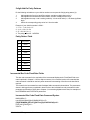
The following is a brief summary of each chapter:
Preface. The preface introduces SmartGraphics and explains the purpose of the manual. It also
describes the standard conventions that will be used and a brief overview of each chapter.
Chapter 1 - General Description. This chapter highlights SmartGraphics features, modes of operation and methods of printing. A brief introduction to printer software is also provided for the novice
user.
Chapter 2 - Normal Mode Commands. This chapter presents the commands that are available
under the Normal Mode of operation. Commands are listed alphabetically according to function for
easy reference.
Chapter 3 - Forms Generation. This chapter includes the commands used to create forms and
logos, as well as forms printing. Methods of incrementing and decrementing data will also be explained. Commands are grouped according to mode and function.
Chapter 4 - Bar Codes. This chapter describes the various bar codes available under SmartGraphics.
Specific instructions for generating those bar codes are supported by illustrative examples.
Chapter 5 - Character Sets and Fonts. This chapter explains how to use command parameters to
select the desired size or font for text printing. Instructions are also provided for creating user-defined
character sets.
Appendix A - Command Summary. This appendix lists all the commands available under the
SmartGraphics IGP emulation.
Appendix B - Character Sets. This appendix provides samples of multinational character sets.
Appendix C - Error Codes. This appendix defines the coded error messages that can result from
improper SmartGraphics command usage.
Appendix D - Description of Options Settings. This appendix describes the various options conditions used to set or change the SmartGraphics default settings.
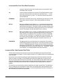
Conventions Used in This Manual
Throughout this manual, the following visual cues and standard text formats will assist you in identifying various elements:
Bold
-
Used to set off headings and important information.
Italics
-
Used for manual names and command titles.
Bullets
-
Bullets (!) itemize information in each section.
ALL CAPS
-
ALL CAPS call your attention to important words.
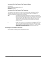
Getting Started
To use the SmartGraphics IGP Printronix emulation, you must enter the PRG:SmartGraphics menu
and select the SGL:IGP Emul option. For detailed instructions on selecting the SmartGraphics option,
see the User’s Manual for the model printer in use.
Preface
ii
PREFACE
Introduction
This manual provides detailed instructions on how to use the SmartGraphics Processor to emulate the
functionality of the Printronix-100 Intelligent Graphics Processor (IGP). All references in this manual
regarding SmartGraphics refer to the SmartGraphics Processor operating under this IGP emulation.
SmartGraphics provides enhanced text and graphics features that include variable-sized and rotated
characters, forms and label generation, as well as variable bar codes. Instructions for utilizing these
SmartGraphics features are presented according to mode of operation and applicable commands.
The following information is presented as each function or command is covered:
•
Mode of Operation
•
Command syntax
•
Explanation and usage
•
Illustrative examples
This manual also includes appendices containing command summaries, conversion tables, error
codes and recovery, and configuration instructions.
Objectives of This Manual
The purpose of this manual is to familiarize you with the capabilities and features of the
SmartGraphics Processor. It is designed to teach you how to use the required SmartGraphics commands. Each command is presented in an easy-to-learn format and illustrated through one or more
representative examples.
Intended Audience
The information provided in this manual will enable the user to take advantage of the desired print
features and functions. Likewise, software developers will find complete technical specifications
necessary to fully utilize SmartGraphics capabilities.
Prerequisite
Though not required, a prior knowledge of programming logic is naturally advantageous. As an aid to
the novice user, an introduction to printer software is provided in Chapter 1.
Manual Organization
This manual provides complete instructions for programming the SmartGraphics Processor. Information is presented as you will need it, starting with the basics. Each operation is illustrated by one or
more examples to help you understand the required command entries and printer functions.
GEK-89149A IGP Programmer’s Manual
i
The following is a brief summary of each chapter:
Preface. The preface introduces SmartGraphics and explains the purpose of the manual. It also
describes the standard conventions that will be used and a brief overview of each chapter.
Chapter 1 - General Description. This chapter highlights SmartGraphics features, modes of operation and methods of printing. A brief introduction to printer software is also provided for the novice
user.
Chapter 2 - Normal Mode Commands. This chapter presents the commands that are available
under the Normal Mode of operation. Commands are listed alphabetically according to function for
easy reference.
Chapter 3 - Forms Generation. This chapter includes the commands used to create forms and
logos, as well as forms printing. Methods of incrementing and decrementing data will also be explained. Commands are grouped according to mode and function.
Chapter 4 - Bar Codes. This chapter describes the various bar codes available under SmartGraphics.
Specific instructions for generating those bar codes are supported by illustrative examples.
Chapter 5 - Character Sets and Fonts. This chapter explains how to use command parameters to
select the desired size or font for text printing. Instructions are also provided for creating user-defined
character sets.
Appendix A - Command Summary. This appendix lists all the commands available under the
SmartGraphics IGP emulation.
Appendix B - Character Sets. This appendix provides samples of multinational character sets.
Appendix C - Error Codes. This appendix defines the coded error messages that can result from
improper SmartGraphics command usage.
Appendix D - Description of Options Settings. This appendix describes the various options conditions used to set or change the SmartGraphics default settings.
Conventions Used in This Manual
Throughout this manual, the following visual cues and standard text formats will assist you in identifying various elements:
Bold
-
Used to set off headings and important information.
Italics
-
Used for manual names and command titles.
Bullets
-
Bullets (!) itemize information in each section.
ALL CAPS
-
ALL CAPS call your attention to important words.
Getting Started
To use the SmartGraphics IGP Printronix emulation, you must enter the PRG:SmartGraphics menu
and select the SGL:IGP Emul option. For detailed instructions on selecting the SmartGraphics option,
see the User’s Manual for the model printer in use.
Preface
ii
Table of Contents
PREFACE ......................................................................................................... I
CHAPTER 1. GENERAL DESCRIPTION ..................................................... 1-1
Introduction ..................................................................................................................... 1-1
How to Turn On IGP Emulation ...................................................................................... 1-1
Printer Emulation ............................................................................................................ 1-1
IGP with Other Emulations .................................................................................................................... 1-2
Features ........................................................................................................................... 1-3
Variable Print Size .................................................................................................................................. 1-3
Reversed Print ........................................................................................................................................ 1-3
Alphanumeric Rotation .......................................................................................................................... 1-3
Logo Creation ......................................................................................................................................... 1-3
Forms and Label Generation ................................................................................................................. 1-3
Fixed, Dynamic, and Overlay Data Printing ......................................................................................... 1-3
Automatic Data Increment/Decrement ................................................................................................. 1-3
Bar Codes ............................................................................................................................................... 1-3
Scaling Function .................................................................................................................................... 1-4
Multinational Character Sets ................................................................................................................. 1-4
Modes of Operation ......................................................................................................... 1-4
Normal Mode .......................................................................................................................................... 1-4
Create Logo Mode .................................................................................................................................. 1-4
Create Form Mode ................................................................................................................................. 1-4
Execute Form Mode ............................................................................................................................... 1-4
Stored Data ............................................................................................................................................. 1-4
Command Syntax Rules ................................................................................................. 1-5
Special Function Control Character <SFCC> ..................................................................................... 1-6
Semicolon (;) .......................................................................................................................................... 1-6
Numeric Value (n) ................................................................................................................................... 1-6
Uppercase ............................................................................................................................................... 1-6
Terminator .............................................................................................................................................. 1-6
GEK-89149A IGP Programmer’s Manual
iii
Printable Character ................................................................................................................................ 1-7
Parentheses ( ) ....................................................................................................................................... 1-7
Brackets [ ] ............................................................................................................................................. 1-7
Other Command Considerations ................................................................................... 1-7
Form Name ............................................................................................................................................. 1-7
Comments .............................................................................................................................................. 1-8
CHAPTER 2. NORMAL MODE COMMANDS ............................................. 2-1
Introduction ..................................................................................................................... 2-1
Compressed Print Command : DENSITY ...................................................................... 2-1
Create Form Mode Command : CREATE ....................................................................... 2-3
Delete Form Command : DELETE FORM ...................................................................... 2-3
Delete Logo Command : DELETE LOGO ...................................................................... 2-3
Directory Command : DIRECTORY ................................................................................ 2-4
Execute Form Mode Command : EXECUTE ................................................................. 2-5
Expanded Print Command : EXPAND ............................................................................ 2-5
Listen Command : LISTEN ............................................................................................. 2-6
Multinational Character Set Commands : ISET / USET................................................ 2-6
Normal Mode Command : NORMAL .............................................................................. 2-6
Quiet Command : QUIET ................................................................................................ 2-7
Reset Command : RESET ............................................................................................... 2-8
Scaling Command : SCALE ............................................................................................ 2-8
Vertical Line Spacing Command : LPI ........................................................................... 2-8
CHAPTER 3. FORMS AND LOGO GENERATION ..................................... 3-1
Create Form Mode Commands ...................................................................................... 3-1
Create Command : CREATE .................................................................................................................. 3-1
Alphanumerics Command : ALPHA ...................................................................................................... 3-2
Incrementing Alphanumeric (or Bar Code) Data : STEPMASK / STARTDATA ................................... 3-6
Incremental Alphanumeric Fixed Data Fields Command : ALPHA .................................................... 3-9
Incremental Alphanumeric Dynamic Data Fields Command : ALPHA ............................................. 3-10
Duplicating Incremental Alphanumeric (or Bar Code) Fields .......................................................... 3-11
Box Command : BOX ........................................................................................................................... 3-12
Table of Contents
iv
Corner Command : CORNER .............................................................................................................. 3-13
End Command : END ........................................................................................................................... 3-14
Form Length : LFORM6 / LFORM8 ..................................................................................................... 3-15
Horizontal Duplication Command : HDUP ......................................................................................... 3-15
Horizontal Lines Command : HORZ ................................................................................................... 3-17
Logo Call Command : LOGO .............................................................................................................. 3-18
Page Number Command : PAGE ......................................................................................................... 3-19
Reverse Print Command : REVERSE ................................................................................................. 3-20
Scale Command : SCALE .................................................................................................................... 3-21
Scale and Character/Dot Position Format Command: CP.DP command CP.DP ............................. 3-22
Vertical Duplication Command: VDUP .............................................................................................. 3-23
Vertical Lines Command : VERT ......................................................................................................... 3-24
Create Logo Mode : LOGO ........................................................................................... 3-26
Execute Form Mode Command : EXECUTE ............................................................... 3-28
Execute Overlay Data : EXECUTE ...................................................................................................... 3-31
Execute Dynamic Alphanumeric Data : EXECUTE ............................................................................ 3-32
Execute Dynamic Bar Code Data : EXECUTE .................................................................................... 3-34
Supplying Incremental Dynamic Data ......................................................................... 3-37
Execute Incremental Dynamic Data : EXECUTE ............................................................................... 3-38
Vertical Paper Motion .................................................................................................... 3-40
Fixed Record Length Utility Modes .................................................................................................... 3-41
Select Format Command : SFON / SFOFF ......................................................................................... 3-41
Ignore Sequence Command : IGON / IGOFF ...................................................................................... 3-42
CHAPTER 4. BAR CODES........................................................................... 4-1
Bar Code Type Summary ................................................................................................ 4-1
Bar Code Structure ......................................................................................................... 4-4
Bar Code Terminology .................................................................................................... 4-4
Quiet Zone .............................................................................................................................................. 4-4
Start/Stop Code ...................................................................................................................................... 4-4
Data Field ................................................................................................................................................ 4-4
Readable Data ........................................................................................................................................ 4-4
Check Digit ............................................................................................................................................. 4-5
Common Bar Code Parameters ............................................................................................................ 4-5
Code 3/9 Bar Code Structure ......................................................................................... 4-8
GEK-89149A IGP Programmer’s Manual
v
Code 128B Bar Code Structure .................................................................................... 4-10
Code 128C Bar Code Structure .................................................................................... 4-14
EAN 8 Bar Code Structure ............................................................................................ 4-17
EAN 13 Bar Code Structure .......................................................................................... 4-19
Interleaved 2/5 Bar Code Structure ............................................................................. 4-22
UPC-A Bar Code Structure ........................................................................................... 4-25
UPC-E Bar Code Structure ........................................................................................... 4-27
MSI Bar Code Structure ................................................................................................ 4-30
POSTNET Bar Code Structure ..................................................................................... 4-33
Bar Code Add-On Data (UPC and EAN styles) ............................................................ 4-34
5-digit Add-On Parity Patterns ............................................................................................................ 4-35
Incremental Bar Code Fixed Data Fields ..................................................................... 4-35
Incremental Bar Code Dynamic Data Fields ............................................................... 4-36
Duplicating Incremental Bar Code Fields ................................................................... 4-37
CHAPTER 5. CHARACTER SETS AND FONTS ......................................... 5-1
Font Types ....................................................................................................................... 5-1
OCR Character Set Selection ......................................................................................... 5-1
Bar Code Font (Printable Data Field) ............................................................................. 5-2
MultinationalCharacter Set ............................................................................................. 5-2
Accessing Characters and Character Sets ................................................................... 5-3
International Character Set Command: ISET ....................................................................................... 5-3
Accessing Characters: Data bit 8 ......................................................................................................... 5-3
User-defined Character Set Command: USET .............................................................. 5-4
APPENDIX A. COMMAND SUMMARY ...................................................... A-1
Normal Mode Commands ............................................................................................... A-1
Create Form Mode Commands ...................................................................................... A-1
Create Form Mode Commands (Continued) ................................................................. A-2
Create Logo Mode Commands ...................................................................................... A-2
Execute Form Mode Commands .................................................................................... A-2
Bar Code Commands ...................................................................................................... A-3
Table of Contents
vi
Bar Code Commands (Continued) ................................................................................. A-4
Incremental Bar Code Commands ................................................................................. A-4
Fixed Length Utility Commands ..................................................................................... A-4
Multinational Character Set Commands ....................................................................... A-4
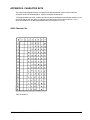
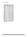
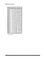
APPENDIX B. CHARACTER SETS ............................................................ B-1
ASCII Character Set ........................................................................................................B-1
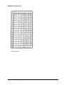
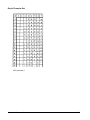
German Character Set ....................................................................................................B-2
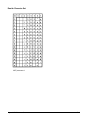
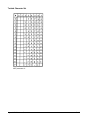
Swedish Character Set ...................................................................................................B-3
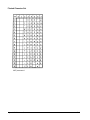
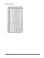
Danish Character Set ......................................................................................................B-4
Norwegian Character Set ...............................................................................................B-5
Finnish Character Set .....................................................................................................B-6
English Character Set .....................................................................................................B-7
Dutch Character Set ........................................................................................................B-8
French Character Set ......................................................................................................B-9
Spanish Character Set ..................................................................................................B-10
Italian Character Set...................................................................................................... B-11
Turkish Character Set ...................................................................................................B-12
OCR-A Character Set ....................................................................................................B-13
OCR-B Character Set ....................................................................................................B-14
Multinational Extended Character Set .........................................................................B-15
APPENDIX C. ERROR CODES................................................................... C-1
Debug Mode .....................................................................................................................C-1
Horizontal Line Command Errors ..................................................................................C-2
Vertical Line Command Errors .......................................................................................C-2
Box Command Errors .....................................................................................................C-3
Corner Command Errors ................................................................................................C-4
Alpha Command Errors ..................................................................................................C-5
Create Logo Command Errors .......................................................................................C-6
Create Errors ...................................................................................................................C-7
Execute Errors .................................................................................................................C-8
GEK-89149A IGP Programmer’s Manual
vii
Miscellaneous Errors ......................................................................................................C-8
Bar Code Errors ..............................................................................................................C-9
Reverse Print Errors ..................................................................................................... C-11
Printer Mode Errors....................................................................................................... C-11
Incremental Field Errors ...............................................................................................C-12
Scaling Command Errors .............................................................................................C-12
Multinational Character Set Errors ..............................................................................C-13
APPENDIX D. DESCRIPTION OF OPTIONS SETTINGS ........................... D-1
Other Models ...................................................................................................................D-1
Interface Type ..................................................................................................................D-1
Parity Type, Data/Stop Bits (Serial) ................................................................................D-2
Transmitting XON When Idle (Serial) .............................................................................D-2
Baud Rate (Serial Only) ..................................................................................................D-3
Reserved For Future Use ...............................................................................................D-3
SmartGraphics Diagnostic Mode ..................................................................................D-4
Density Bar Codes Densities .........................................................................................D-4
XOFF CONTROL ..............................................................................................................D-4
P-Series SFCC Mode ONLY ............................................................................................D-5
Not Used By IGP ..............................................................................................................D-5
Special Function Control Character - IGP(SFCC) .........................................................D-5
Character Set Select .......................................................................................................D-6
Sequence Terminator ......................................................................................................D-6
Delete Logo Control ........................................................................................................D-7
Power Up in Quiet Mode .................................................................................................D-7
Enable Default to OCR-B ................................................................................................D-7
Reserved for Future Use .................................................................................................D-7
Error Reporting................................................................................................................D-8
Multisource Selection .....................................................................................................D-8
Multisource Interface Delay ............................................................................................D-8
Ignore Character Selection .............................................................................................D-9
Reserved for future use ..................................................................................................D-9
Table of Contents
viii
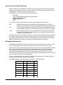
3800/3900 Series - Checking Status and Setting Options ...........................................D-9
4800/4900 Series - Checking Status and Setting Straps............................................D-10
5000 Series - Status and Setting Options ...................................................................D-10
GEK-89149A IGP Programmer’s Manual
ix
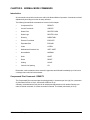
CHAPTER 1. GENERAL DESCRIPTION
Introduction
This chapter gives a brief overview of SmartGraphics features and command conventions. The
following information is included:
• Features
• Entering commands
• Modes of Operation
How to Turn On IGP Emulation
To turn ENABLE the IGP emulation, use the printer control panel to enter the LCD menu tree, find the
SmartGraphics or SGL menu, and then select IGP. See the user’s manual for the printer in use for
more information.
Printer Emulation
Some printers have the ability to emulate (function similar to) a printer made by a different manufacturer. The SmartGraphics Processor can emulate a Printronix printer with the IGP-100 option installed.
Under the IGP emulation, SmartGraphics supports a powerful command set that consists primarily of
English text.
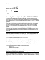
Any of the SmartGraphics print samples presented in this manual can be duplicated by creating an
ASCII text file that contains the command lines shown in the example. To illustrate, use an editor of
your choice, to create a file with two lines:
~DENSITY;17
This is 17 cpi
NOTE: There must be no blank spaces in front of a command. Lines of code can not be indented when programming in this language.
Save the file under the file name TEST, then copy the file to the printer with the DOS command:
copy test prn
GEK-89149A IGP Programmer’s Manual
1-1
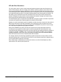
IGP with Other Emulations
For every printer, there is a set of control codes and escape sequences that control features of the
printer such as margins, tabs, form length, pitch, boldface, underline, graphics, and so forth. Such a
control set originates with a printer manufacturer. If a particular printer model has been widely used, its
control set may survive the obsolescence of the printer. If you have drivers for, say, a ProPrinter, then
you might prefer that any printer in your office/company would function as (emluate) a ProPrinter. For
that reason, printer manufacturers provide emulations of the control sets of other manufacturers’
printers. Existing drivers may remain in service through several printer changes, and certain emulations become de-facto standard printer control languages.
The SmartGraphics option is a printed circuit board with a processor, firmware, and other components
neccessary to implement two industrial graphics emulations: IGP and QMS.
Whether or not the SmartGraphics option is installed or enabled, the native control set for this printer is
ANSI X3.64. Alternative control sets (emulations) can be selected from the emulation menu on the
control panel, or in some cases, from the host. Before IGP is ENABLED, the printer is in some emulation. Let’s call that emulation the pre-graphics emulation.
When IGP is ENABLED, the printer continues to interpret control codes and escape sequences
according to the pre-graphics emulation until it receives a bona-fide IGP control sequence. It processes that and all subsequent input as IGP until a bona-fide IGP terminating command or condition is
received, for example, ~NORMAL. Then, it reverts to the pre-graphics emulation. Any pre-graphics
emulation parameters, such as font, pitch, print quality, form length, and so forth that were selected
before IGP data was received are re-asserted when IGP terminates.
For example, assume the selected (pre-graphics) emulation is Proprinter, and you want to mix IGP
jobs with Proprinter jobs. You don’t have to turn off IGP to use Proprinter except in the situation where
your Proprinter data includes IGP commands.
On the other hand, if a ASCII dump of an IGP job is desired, turn off the SmartGraphics (or SGL)
option and the IGP code will print as plain text.
Chapter 1. General Description
1-2
Features
The SmartGraphics Processor provides a variety of enhanced graphics and printing capabilities. The
following is a brief overview of these features.
Variable Print Size
Alphanumeric height and width can be independently controlled over a range of sizes up to 9.9 inches
(vertically and horizontally). Compressed print sizes available are 13, 15, and 17 characters per inch
(cpi). At 17 cpi, you can print up to 136 characters in an 8-inch printed area.
Reversed Print
Printing white characters on a dark background (reversed print) allows you to achieve highlighting and
contrasting effects.
Alphanumeric Rotation
To permit enhanced forms design and creativity, characters (normal, expanded, and compressed) can
be rotated 90, 180, and 270 degrees.
Logo Creation
Logos can be created and added to forms and listings by using alphanumeric commands and a variety
of print and shading features.
Forms and Label Generation
Form and label designs can be created and then duplicated horizontally and vertically to give a
“preprinted” appearance. Graphic features include boxes, vertical and horizontal solid and dashed
lines (with variable thickness), logos, and special alphanumeric print methods: fixed, overlay and
dynamic data.
Fixed, Dynamic, and Overlay Data Printing
Alphanumeric data can be printed on forms in three ways: “fixed” data, entered when the form is
created (e.g., company name and address); “dynamic” data that is entered by command when the
form is executed (e.g., quantity and amount).; “overlay” data, printed in a specified location when the
form is executed to provide a “filled-in” look (e.g., customer name and address)
Automatic Data Increment/Decrement
Data fields (alphanumeric and bar code) can be automatically incremented or decremented. The user
can specify both the beginning value and increment/decrement value.
Bar Codes
Bar code styles can be printed in a regular or dark mode using standard or user-selected ratios. The
following bar code styles are available: Code 3 of 9, Interleaved 2 of 5, UPC-A, UPC-E, MSI A through
D, Code 128 Subset B and C, EAN 8, EAN 13, and POSTNET.
GEK-89149A IGP Programmer’s Manual
1-3
Scaling Function
Graphic elements (e.g., boxes, corners, etc.) can be scaled so that they retain their physical characteristics when printed in horizontal or vertical densities other than the base density of 60 x 72 dots per
inch.
Multinational Character Sets
SmartGraphics provides the user with many foreign character sets (96 characters in length). You can
also create your own character sets using characters already defined in the font memory.
Modes of Operation
SmartGraphics supports four modes of operation: Normal, Create Form, Create Logo, and Execute
Form. You select the mode of operation and the task to be performed by sending a sequence of
commands to the printer. Each mode has specific commands which are valid in that mode.
Normal Mode
In Normal Mode, the printer monitors the data stream until a Special Function Control Character
(SFCC) is detected.Until a SFCC is received, no IGP processing takes place. A SFCC identifies the
start of a command to enable a SmartGraphics function. The SFCC default is a tilde “~”; however, this
can be changed to a different character in the printer’s menu.
Create Logo Mode
The Create Logo Mode is used to design a logo to be printed on any document (i.e., form, report, or
listing). The logo is created, not printed, under the Create Logo Mode, it is printed during the Execute
Form Mode when the document is printed. Only logo-related error messages will be printed during the
Create Logo Mode.
Create Form Mode
The Create Form Mode allows design of forms, form elements, and bar codes. Graphics including
lines, boxes, corners, bar codes, data, and previously defined logos can be defined as part of a
specific form by using the appropriate commands. The form is not printed under the Create Form
Mode; it is printed during the Execute Form Mode. Only applicable error messages will be printed
during the Create Form Mode.
Execute Form Mode
Documents are printed under the Execute Form Mode. Various print features are available (e.g.,
compressed print, elongated characters, etc.). The alternate character set can also be used.
Stored Data
Data stored in the printer’s memory remains there until it is deleted by a command, power is removed,
or the reset command is received.
Chapter 1. General Description
1-4
Command Syntax Rules
SmartGraphics commands have a specific format that must be followed for proper operation. Failure
to comply to the required syntax will result in indeterminate operation. The following subsections
specify the syntax rules used for commands. Examples are provided to illustrate each rule.
Throughout this manual, commands are presented as follows:
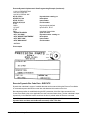
Compressed Print (Density) Command Syntax:
<SFCC>DENSITY;n<LF>
Parameters in Command Syntax:
<SFCC>
Special Function Control Character. Unless changed by in the printer’s menu,
TILDE (~) is the default SFCC.
DENSITY
Character Density Command
n
Selects the density in cpi. Replace "n" with 10,12,13,15,17, 10A or 10B.
<LF> (or <CR><LF>)
Terminator
The following applicable syntax examples are based on the above DENSITY command. A mark
indicates the correct syntax usage; the X indicates incorrect usage of the applicable command character or parameter.
GEK-89149A IGP Programmer’s Manual
1-5
Special Function Control Character <SFCC>
The Special Function Control Character (SFCC) identifies beginning of an IGP command. Various
characters can be selected as the SFCC (the tilde “~” character is used as a default and will be used
in all examples). The SFCC must be placed at the beginning of a line.
Example: Set compressed print (17 cpi)
( [ ) ~DENSITY;17
( X ) DENSITY;17
Semicolon (;)
A semicolon must be used to separate each parameter (alpha data, numeric data, options, etc.) of the
command. No blank spaces are allowed between the semicolon and the next parameter. A missing or
misplaced semicolon will result in an error message.
Example:
( [ ) ~DENSITY;17
( X ) ~DENSITY 17
Numeric Value (n)
Throughout this manual, a lowercase n is used to represent a numeric value in the command stream.
If a command includes this n parameter, you must substitute the appropriate numeric value in place of
the n. No value is required if the lowercase n is part of an optional, unused command parameter.
Example:
( [ ) ~DENSITY;17
( X ) ~DENSITY
Uppercase
ALL commands and form names must be entered in uppercase.
Example:
( [ ) ~DENSITY;17
( X ) ~Density;17
Terminator
For the printer to accept the command line, it MUST be followed by a LINEFEED or a carriage return
with line feed terminator. A command line without a terminator will not be accepted.
Example:
( [ ) ~DENSITY;17
( X ) ~DENSITY;17;
Chapter 1. General Description
1-6
Printable Character
Alphanumeric and bar code data must be bordered by a printable character (a delimiter). Double
quotes (“) will be used as the delimiter throughout this manual. Any printable character other than a
space, slash (/), or the SFCC can be used as the delimiter. The same printable character must occur
before the first character and after the last character of the text; it cannot occur within the text.
Example:
( [ ) Print 17 cpi sample
( X ) Print 17 ”cpi” sample
(Delimiter cannot be used within the text.)
( X ) dog biscuits taste good
(Printed result: og biscuits taste goo. The lowercase d positioned at the beginning and end of the text
is interpreted as the delimiter.)
Parentheses ( )
Parentheses denote variable data. You have a choice of what to enter, but you MUST enter something
at this point in the command line. Do not enter the parentheses themselves.
Example:
( [ ) DPrint 17 cpi sampleD
( [ ) Print 17 cpi sample
( X ) (D)Print 17 cpi sample(D)
Brackets [ ]
An optional command parameter is shown inside brackets. To use the option, include the data within
the brackets, but do not enter the brackets themselves.
Example:
( [ ) ~SCALE;CHAR;8;13
( X ) ~SCALE;CHAR[;8;13]
Other Command Considerations
Form Name
Up to eight (8) alphanumeric characters (no spaces) can be used to identify the form being created.
The form name is used to identify the form during Execute Form Mode.
Example:
( [ ) ~CREATE;FORM001
( X ) CREATE;FORM 001
GEK-89149A IGP Programmer’s Manual
1-7
Comments
Comments can be added to a command line or on a separate line to aid in preparation or maintenance
of a form or logo. Comments must be preceded by a “/” slash command.
Example:
( [ ) ~CREATE;FORM001
( X ) CREATE;FORM 001
Chapter 1. General Description
/FORM #1
FORM #1
1-8
CHAPTER 2. NORMAL MODE COMMANDS
Introduction
All commands covered in this section are valid in the Normal Mode of operation. Commands are listed
alphabetically according to function for easy reference.
The following Normal Mode commands are covered in this chapter:
•
Compressed Print
DENSITY
•
Create Form Mode
CREATE
•
Delete Form
DELETE FORM
•
Delete Logo
DELETE LOGO
•
Directory
DIRECTORY
•
Execute Form Mode
EXECUTE
•
Expanded Print
EXPAND
•
Listen
LISTEN
•
Multinational Character Set
ISET / USET
•
Normal Mode
NORMAL
•
Quiet
QUIET
•
Reset
RESET
•
Scaling
SCALE
•
Vertical Line Spacing
LPI
Remember, each command must be entered in uppercase and followed immediately by a line feed or
a carriage return with line feed terminator.
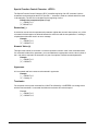
Compressed Print Command : DENSITY
The Compressed Print command sets the printing density in characters per inch (cpi). An n parameter
of 10A selects OCR-A at 10 cpi; 10B selects OCR-B at 10 cpi.
A Density command sets the print size for all subsequent alphanumerics until another Density command, a Normal command, or a Reset command is entered. The default print density is 10 cpi.
GEK-89149A IGP Programmer’s Manual
2-1
DENSITY Command Syntax:
<SFCC>DENSITY;n<LF>
DENSITY Parameters:
<SFCC>
Special Function Control Character. The default is TILDE (~).
DENSITY
Character Density Command
n
Selects the density in cpi. Replace “n” with 10,12,13,15,17, 10A or 10B.
<LF>
Terminator
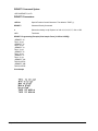
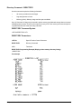
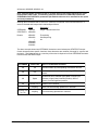
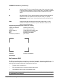
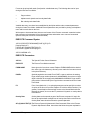
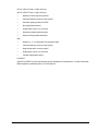
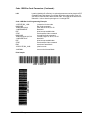
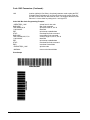
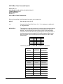
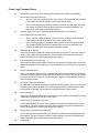
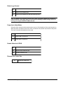
DENSITY Programming Example (Print Sample Fonts [10 CPI to OCR-B]):
~DENSITY;10
This is 10 cpi
~DENSITY;12
This is 12 cpi
~DENSITY;13
This is 13 cpi
~DENSITY;15
This is 15 cpi
~DENSITY;17
This is 17 cpi
~DENSITY;10A
THIS IS OCR-A
~DENSITY;10B
THIS IS OCR-B
Print Sample
Chapter 2. Normal Mode Commands
2-2
Create Form Mode Command : CREATE
This command puts IGP in the Create Form Mode. In this mode, applicable commands are used to
design form elements.
(Refer to Chapter 3 for command syntax and example.)
Delete Form Command : DELETE FORM
The Delete Form command is used to delete a form (identified by form name) from the directory and
printer memory. If the SmartGraphics DELETE LOGOS option is ENABLED, then any logos associated with this form will also be deleted.
(See Smartgraphics options description in Appendix D.)
DELETE FORM Command Syntax:
<SPCC>DELETE FORM;FORMNAME<LF>
DELETE FORM Parameters:
<SFCC>
Special Function Control Character.
DELETE
Delete Form Command
FORMNAME
Name of form to delete. The entire form directory can be deleted by entering
*ALL as the FORMNAME.
<LF>
Terminator
DELETE FORM Programming Example (Delete a form named LABEL) :
~DELETE FORM;LABEL
Delete Logo Command : DELETE LOGO
The Delete Logo command deletes the logo from the directory and printer memory. Once a logo is
deleted, any attempt to print a form containing that logo will produce an error message.
DELETE LOGO Command Syntax:
<SFCC>DELETE LOGO;LOGONAME<LF>
DELETE LOGO Parameters:
<SFCC>
Special Function Control Character.
DELETE
Delete LOGO Command
LOGONAME
Name of Logo to be deleted. Enter the name exactly as it was created. The
entire logo directory can be deleted by entering *ALL as the LOGONAME.
<LF>
Terminator
DELETE LOGO Programming Example (Delete a logo named NUT):
~DELETE LOGO;NUT
GEK-89149A IGP Programmer’s Manual
2-3
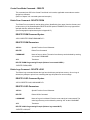
Directory Command : DIRECTORY
Use this command to print the following information:
•
All memory resident forms and logos
•
Logo assignments to forms
•
Memory (printer) Memory usage and free space available
Up to 32 forms and 16 logos may be stored in printer memory provided total storage does not exceed
available printer memory. The form will not print if memory is full. Free memory area must be equal to
or greater than the size of the form being executed.
DIRECTORY Command Syntax:
<SFCC>DIRECTORY<LF>
DIRECTORY Parameters:
<SFCC>
Special Function Control Character.
DIRECTORY
Directory Command
<LF>
Terminator
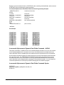
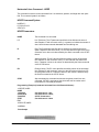
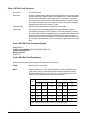
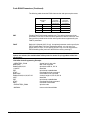
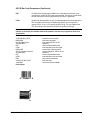
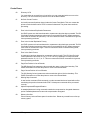
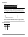
DIRECTORY Programming Example (Display printer memory directory listing):
~DIRECTORY
Print Sample
Chapter 2. Normal Mode Commands
2-4
Execute Form Mode Command : EXECUTE
The Execute Form Mode command executes a previously created form.
Refer to Chapter 3 for command syntax and example.
Expanded Print Command : EXPAND
Use the Expanded Print command to enlarge alphanumeric characters vertically (character height)
and horizontally (character width) up to 99 times the standard size. Both the VE and HE parameters
must be zero or greater. A VE or HE setting of 1 gives single size characters using the expanded font;
a setting of 0 results in standard size characters.
All alphanumerics following an Expanded Print command will be printed at the specified VE and HE
values until the occurrence of another Expanded Print command, a Normal Mode command, or a
Reset command.
EXPAND Command Syntax:
<SFCC>EXPAND;VE;HE<LF>
EXPAND Parameters:
<SFCC>
Special Function Control Character.
EXPAND
Expanded Print Command
VE
Indicates the vertical expansion factor. Range = 0 to 113.
HE
Indicates the horizontal expansion factor. Range = 0 to 113.
<LF>
Terminator
Example: .
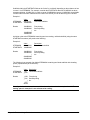
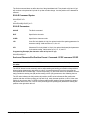
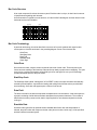
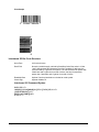
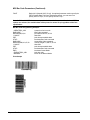
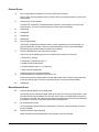
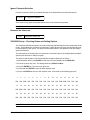
EXPAND Programming Example (Print characters at the standard size, then set vertical and
horizontal expansion at twice the standard size and print):
~NORMAL
ABC123
~EXPAND;2;2
ABC123
~NORMAL
/Normal Mode (no expansion)
/Expand characters 2x2
/return to Normal Mode
Print Sample
GEK-89149A IGP Programmer’s Manual
2-5
Listen Command : LISTEN
The Listen command returns the printer from the QUIET state to the standard operation state (see
QUIET command). In standard mode of operation, valid IGP commands are executed by the
SmartGraphics processor.
LISTEN Command Syntax:
<SFCC>LISTEN<LF>
LISTEN Parameters:
<SFCC>
Special Function Control Character.
LISTEN
Listen Command
<LF>
Terminator
Example: .
Programming Example (Enable standard operation):
~LISTEN
Multinational Character Set Commands : ISET / USET
The ISET (International Character Set) and USET (User-Defined Character Set) commands provide
access to multinational and custom character sets.
(Refer to Chapter 5, Multinational Character Sets.)
Normal Mode Command : NORMAL
SmartGraphics is automatically set for Normal Mode when power is applied, or after a reset is issued
to the SmartGraphics controller (this occurs following any change from the SmartGraphics menu). Use
the Normal Mode command to return the printer to the Normal Mode of operation after performing a
function under one of the other three mode commands (EXECUTE, CREATE or LOGO). In Normal
Mode, the printer does not process (change) the data stream, but looks for the SFCC valid IGP
commands.
Note: A Normal command following an Execute command must be preceded by an blank line
(<LF>).
NORMAL Command Syntax:
<SFCC>NORMAL<LF>
NORMAL Programming Example (Return the printer to the Normal Mode):
~NORMAL
Chapter 2. Normal Mode Commands
2-6
Quiet Command : QUIET
Use the QUIET command to put the printer in the Quiet state. In Quiet state, all data, including valid
IGP commands, are passed to the printer and not executed by the SmartGraphics processor. The
printer will remain in the Quiet state until the next occurrence of a LISTEN command that enables
standard printer operation.
The following commands are valid in the Quiet state:
Listen
Select Format On
Select Format Off
Ignore Sequence On
Ignore Sequence Off
LISTEN
SFON
SFOFF
IGON
IGOFF
Note: The printer will ignore the QUIET command in Execute Form Mode.
QUIET Command Syntax:
<SFCC>QUIET<LF>
QUIET Parameters:
<SFCC>
Special Function Control Character.
QUIET
Quiet Command
<LF>
Terminator
Example: To print a listing of a file that contains SmartGraphics commands. Send a QUIET command
prior to sending the file to the printer.
QUIET Programming Example:
~NORMAL
~QUIET
• • •
~LISTEN
GEK-89149A IGP Programmer’s Manual
set to Normal Mode
tell SmartGraphics to NOT process IGP commands.
print the program listing
return printer to standard operation
2-7
Reset Command : RESET
The RESET command deletes all forms and logos from printer memory. A reset can also be accomplished by cycling power (turning the printer off and on) or by changing a SmartGraphics parameter
from the control panel menu.
RESET Command Syntax:
<SFCC>RESET<LF>
RESET Parameters:
<SFCC>
Special Function Control Character.
RESET
Reset Command
<LF>
Terminator
RESET Programming Example (Reset the printer):
~RESET
Scaling Command : SCALE
The Scaling command sets the vertical and horizontal pitch for form printing.
Refer to Chapter 3 for command syntax and example.
Vertical Line Spacing Command : LPI
Use the Vertical Line Spacing Command to select the vertical printing format. Default line spacing is 6
lpi (lines per inch). All subsequent text after an LPI will be printed at the new LPI until the occurrence
of another LPI command, a Normal Mode Command, or a Reset Command.
LPI Command Syntax:
<SFCC>LPI;n<LF>
LPI Parameters:
<SFCC>
Special Function Control Character.
LPI
Vertical Line Spacing Command
n
Sets line spacing in lpi:6,8,9, or 10.
<LF>
Terminator
Chapter 2. Normal Mode Commands
2-8
LPI Programming Example (Set SmartGraphics vertical line spacing to 8 lpi):
~LPI;8
Note: The LPI command affects only printed alphanumerics; the printer line spacing is not
changed. Therefore, if the printer receives an 8 lpi command while SmartGraphics is set to 9 or
10 lpi, the top of the first character line may be cut off. This truncation can be avoided by
issuing two line feeds before the 8 lpi data stream. You could also set the SmartGraphics
option CR=LF, and then send a carriage return and line feed prior to the 8 lpi data stream.
GEK-89149A IGP Programmer’s Manual
2-9
CHAPTER 3. FORMS AND LOGO GENERATION
This section includes the commands used to create forms and logos, as well as forms printing. Methods of incrementing and decrementing data will also be explained. Commands are grouped according
to mode and function.
The following commands and functions are explained in detail. Illustrative examples are provided
where applicable.
Create Form Mode Commands
Create Command
Alphanumerics
Boxes
Corners
End Command
Form Length
Horizontal Duplication
Horizontal Lines
Logo Call
Page Number
Reverse Print
Scale
Scale and CP.DP Format
Vertical Duplication
Vertical Lines
CREATE
ALPHA
BOX
CORNER
END
LFORM6 / LFORM8
HDUP
HORZ
LOGO
PAGE
REVERSE
SCALE
CP.DP
VDUP
VERT
Create Logo Mode
LOGO
Execute Form Mode
EXECUTE
Create Form Mode Commands
The Create Form Mode commands are used to design forms, all form components (boxes, corners,
etc.), and bar codes. Forms are not printed in the Create Form Mode, they are printed in the Execute
Form Mode after all form design is complete. Each form element has its own specific set of commands
and parameters that determine size, location, and content.
Create Command : CREATE
To begin form design, the Create Form Mode must be accessed using the Create command.
CREATE Command Syntax:
<SFCC>CREATE;[/]FORMNAME[;FL]<LF>
GEK-89149A IGP Programmer’s Manual
3-1
CREATE Parameters:
<SFCC>
Special Function Control Character.
CREATE
Create Form Mode Command
/
An optional debug parameter that checks each line in the program for invalid
characters and parameters. The program is evaluated when you attempt to
print the form under the Execute Mode. It is then that the form is actually
stored in printer memory and the form name entered into the directory. Error
messages will be printed for any errors found. The correct program equations
will be stored. Ultimately, you must correct all errors and delete the /. The
form will not be produced if the / is left in the program.
Note: The / may exist outside the parameter string; e.g., to precede a comment line.”
FORMNAME
Defines the name of the form being created. The form name may contain a
maximum of eight alphanumeric characters. No spaces, semicolons, slashes,
or the SFCC are allowed. An existing form with the same name will be
overwritten and replaced. Any future editing, executing, or deleting of the form
must be done using the assigned name.
FL
Form Length. Use this optional parameter to designate the maximum length
of the form in dot rows (6 lpi line spacing yields 12 dot rows per line; 8 lpi line
spacing yields 9 dot rows per line). The default length of 792 dot rows (11
inches at 6 lpi) will be used if this parameter is left blank. You can enter a
value (1 to 65,535) to specify Form Length in dot rows. You can also enter 0
to denote an unspecified length. If 0 is used, the form will end automatically
after the last element has been printed.
CREATE Programming Example:
(Create a form named SAMPLE with an automatic form length)
~CREATE;SAMPLE;0
ALPHA
C17;20;15;0;0;”EEEE”
...
...
STOP
END
/create sample form
/17 cpi spacing
...
...
/terminate Alpha command
/terminate Create Mode
Note: A complete program and resulting output is shown under Alpha command example.
Alphanumerics Command : ALPHA
The standard Alpha command is used to define and position a data field on a form. Other forms of the
Alpha command are used to automatically increment, decrement, duplicate, and reset alphanumeric
data field values (see Incrementing Alphanumeric Data).
Depending on the parameters used, a printed alphanumeric data field will be treated as either static
(preprinted) or dynamic data. Dynamic data is entered when the form is printed. The Position data
position of a dynamic data field is set under the Create Form Mode; the entered alphanumeric data
must be redefined before each print when the form is produced under the Execute Form Mode.
Chapter 3. Forms and Logo Generation
3-2
In addition to alphanumeric data string entry, Alpha command parameters provide the following data
field manipulation options:
•
90 degrees clockwise and counterclockwise rotation
•
180 degrees rotation (inverted print)
•
Reverse print (white on black) with two density options
•
Elongated character printing (non-rotated printing only)
•
Compressed print settings (non-rotated printing only)
•
Dynamic data field positioning
•
Vertical and horizontal character expansion
ALPHA Command Syntax:
ALPHA<LF>
[R[D][L];][E;][Cn;][AFn;L;][DIR;[UC;]]SR;SC;VE;HE;
(D)ASCII Text(D)<LF>
STOP<LF>
ALPHA Parameters:
ALPHA
Alphanumeric Command
R[D][L]
Reverse, Dense and Long Field: R and RD are optional reverse print parameters. An R specifies a black background; RD specifies a denser black
background. The L (Long field parameter) option is used only when defining a
dynamic data field (for either horizontal or rotated print). The L specifies a
long background field to include descended characters, such as lowercase j,
g, y, and p, parts of which print below the base line.
Note: The L option is not required for a static data field; the reverse field length will be adjusted automatically to include descenders.
E
Elongation: The optional E parameter specifies elongated character printing
(approximately double height and single width). If the E option is used, the VE
and HE parameters must be set to 0 to avoid an error. The E option is not
allowed with rotated alphanumerics.
Cn
Compressed Print: Optional horizontal compressed print parameter. If used,
C must be followed by an n value of 10, 12, 13, 15, or 17 to specify cpi
(characters per inch), or 10A for 10 cpi OCR-A or 10B for 10 cpi OCR-B. If
the Cn option is used, the VE and HE parameters must be set to 0 to avoid an
error. The Cn option is not allowed with rotated alphanumerics.
GEK-89149A IGP Programmer’s Manual
3-3
ALPHA Parameters (Continued):
AFn;L
Form Location and Length: An optional parameter used to identify form
location and length of a dynamic data field. If used, the actual text cannot be
entered during the Create Form Mode (Do not use the ALPHA TEXT parameter). Dynamic text is entered during the Execute Form Mode, so it can be
changed without redefining or recreating the form, refer to Execute Dynamic
Alphanumeric Data.
To use the AFn;L option, replace n with a number (1 to 127) to specify the
alphanumeric string location on the form. The SR and SC parameters specify
the precise position (starting row and column) for field n. For L (length), enter
the maximum number of characters (1-226) allowed for this alphanumeric
string. The number of characters of dynamically entered text must be equal to
or less than the assigned L value. Refer to Execute Dynamic Alphanumeric
Data.
DIR;[UC]
Direction: Optional parameter for rotating a character string. No entry is
required for standard horizontal print orientation. The UC (Upper Case only)
parameter can be used to print rotated uppercase characters on the full page
width. DIR is actually replaced with directional codes as follows:
CW = 90° clockwise rotation
CCW = 90° counterclockwise rotation
INV = 180° rotation (for inverted print)
The CW, CCW or INV can be followed by UC, if you wish to specify uppercase characters only. The UC option will convert all lowercase alpha characters to uppercase.
Note: The E (Elongated) and Cn (Compressed Print) options are not allowed with rotated
characters.
SR
Starting Row: The SR value specifies the Starting Row position of the alphanumeric data (either static or dynamic). Replace SR with a numeric value (1
to one less than the length of the form). Character row or dot row is determined by the Scale command or the CP.DP format.
SC
Starting Column: The SC value specifies the Starting Column position of the
alphanumeric data (either static or dynamic). Replace SC with a numeric
value (1 to one less than the width of the form). Character column or dot
column is determined by the Scale command or the CP.DP format.
VE
Vertical Expansion: The VE value is a factor for vertical enlargement of
characters. Enter a numeric value (0 to 113). Zero specifies the standard font
(no expansion). Both VE and HE factors must be zero or non-zero; characters
cannot be enlarged in one plane only. VE and HE can contain different nonzero factors.
Note: The E (Elongated) and Cn (Compressed Print) parameters cannot be used with a nonzero vertical expansion.
Chapter 3. Forms and Logo Generation
3-4
ALPHA Parameters (Continued):
HE
Horizontal Expansion: The HE value is a factor for horizontal enlargement of
characters. Enter a numeric value (0 to 113). Zero specifies the standard font
(no expansion). Both VE and HE factors must be zero or non-zero; characters
cannot be enlarged in one plane only. VE and HE can contain different nonzero factors.
D
Delimiter: Used to denote the start and finish of the alphanumeric string
(ASCII TEXT). Use any printable character other than a /, the SFCC, or a
character used within the string itself. Quotation marks (“) are most commonly
used to denote both ends of an alphanumeric string. The delimiter is not
printed.
ASCII TEXT
The alphanumeric to be printed. Enter any of the standard ASCII printable
characters except the character used as the delimiter or D parameter. This
static, or fixed data, appears prepositioned on the form at the position by the
SR and SC parameters. Unlike dynamic data, this data can be changed only
by redefining the form with the Alpha command under the Create Form Mode.
STOP
Stop terminates this command and causes the printer to wait for a new
command. If STOP is not entered, the printer will wait for another set of Alpha
command parameters.
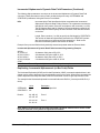
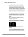
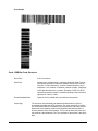
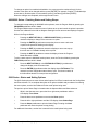
Example: The following is an illustration of Alpha command capabilities showing various print sizes,
rotation, and positioning of static data.
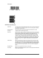
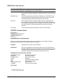
ALPHA Programming Example:
~CREATE;SAMPLE;0
ALPHA
C17;20;15;0;0;”EEEE”
C15;20;18;0;0;”EEEE”
C13;20;21;0;0;”EEEE”
20;24;1;2;”X”
20;26;2;1;”P”
20;27.5;3;2;”A”
20;30;3;3;”N”
20;33;4;3;”D”
R;23;28;0;0;”REVERSE”
CCW;24;15;0;0;”Tilt”
CW;22;24;0;0;”Tip”
INV;26;20;0;0;”Flip”
STOP
END
~EXECUTE;SAMPLE
~NORMAL
GEK-89149A IGP Programmer’s Manual
/create sample form
/17 cpi spacing
/15 cpi spacing
/13 cpi spacing
/expand print x1 VE, x2 HE
/expand print x2 VE, x1 HE
/expand print x3 VE, x2 HE
/expand print x3 VE, x3 HE
/expand print x4 VE, x3 HE
/reverse
/counterclockwise
/clockwise
/invert
/terminate Create Mode
/print sample
/return to Normal Mode
3-5
Print Sample
Incrementing Alphanumeric (or Bar Code) Data : STEPMASK / STARTDATA
This feature is useful for automatic incrementing of data fields, such as item numbers on invoice
forms, boxes or carton labels. This updating function is generally referred to as the incremental field
feature. Whether the data is actually incremented or decremented depends on the sign (+/-) direction
parameter.
The incremental field feature can be used with either fixed (static) or dynamic data. As with the Alpha
(or bar code) command used in the Create Form Mode, additional Execute Form command parameters are required to use this feature with dynamically entered data (see Execute command). A
maximum of 255 incremental static (fixed) alphanumeric fields per form (up to 65,535 forms) are
allowed..
Before explaining Alpha command format, the STEPMASK and STARTDATA parameters that control
incrementing need to be explained. These parameters can be part of both the Incremental Alphanumeric Fixed Data command and the Execute command when using Incremental Alphanumeric Dynamic Data.
Note: The equivalent bar code commands, Incremental Bar Code;increment/decrement Bar
Code Fixed Data and Incremental Bar Code Dynamic Data, will be covered in Chapter 4. The
incremental parameter functions are the same, but the bar code command syntax is quite
different from the Alpha command. The following STEPMASK and STARTDATA explanation
Alpha and bar code commands.
The STEPMASK STEPMASK parameter performs three functions:
1)
2)
3)
specifies the increment value (step)
specifies the number of characters allowed in the data field (STARTDATA)
provides a mask to control incrementing of linked or unlinked parts (subfields) of the data field.
The STARTDATA parameter contains the starting value of the data field. The number of characters
must be equal to or less than the number of characters in the STEPMASK parameter. Where the
number of alphanumeric characters is less, the data will be right justified and preceded by spaces.
These characters are allowed in STARTDATA fields to be incremented:
Numerics, 0 - 9.
Alpha, A - Z (uppercase only).
Any printable character is allowed in non-incrementing fields.
Note: Bar code STARTDATA values are determined by the type of bar code being used. Refer
to Chapter 4 for individual bar code specifications.
Example: A STEPMASK of 000001 will increment a 7-character STARTDATA value by one with each
printing. In other words, a STARTDATA of “AB34560” will become AB34561, AB34562, etc.; AB3456A
Chapter 3. Forms and Logo Generation
3-6
will become AB3456B, AB3456C, etc.
Note: Complete Alpha command syntax is covered under Incrementing Alphanumeric Fixed
(and Dynamic) Data Fields. The following examples illustrate the relationship between the
STEPMASK and STARTDATA parameters (the default values are to be assumed for the repeat
and reset parameters).
Although the STEPMASK and STARTDATA values are not entered in this command format, it is
easier to illustrate and interpret their relationship as follows:
STEPMASK
STARTDATA
Results
Value
0000001
AB34560
Description
Single 7-alphanumeric field
AB34561
AB34562
|
AB99999
AC00000
AC00001
First printing
Second printing
etc.
The above example shows how STEPMASK characters control subsequent STARTDATA output.
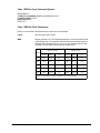
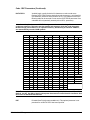
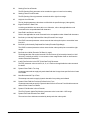
Certain characters have specific functions; these characters are numbers (0 through 9), a space, and
the letter L. The following table is a summary of the rules for Alpha or bar code STEPMASK character
function and STARTDATA output:
STEPMASK
STARTDATA
0-9
0-9
Increment number by corresponding STEPMASK amount.
0-9
A-Z
Increment alpha character by corresponding STEPMASK
amount.
0-9
S p a ce
Will become same character type (alpha or numeric) as
character to right (linked increment position). Will be
numeric if in least significant position.
0-9
Effect on STARTDATA Contents
Not 0-9 or A-Z Results in error condition.
L
Anything
Linked, non-incrementing alphanumeric character.
Anything Else
(e.g.,X)
Anything
Non-incrementing alphanumeric character.
GEK-89149A IGP Programmer’s Manual
3-7
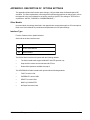
Subfields within the STARTDATA field can be “linked” or “unlinked” depending on the existence of one
or more L’s in STEPMASK. For example, consider the STARTDATA data field 123ABC001 as three
separate subfields: 123/ABC/001. In order to cause 123ABC999 to become 124ABC000, the subfields
on either side of the ABC subfield must be linked. Here is how you can do that using the L variable:
Example 1:
STEPMASK
STARTDATA
Results
Value
000LLL001
123ABC900
Description
Two linked subfields
123ABC901
123ABC902
|
123ABC999
124ABC000
First printing
Second printing
etc.
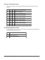
An Alpha or bar code STEPMASK containing two incrementing, unlinked subfields (using the same
STARTDATA as above) will produce the following:
Example 2:
STEPMASK
STARTDATA
Results
Value
001XXX001
123ABC900
Description
Two unlinked subfields
124ABC901
125ABC902
|
222ABC999
223ABC000
First printing
Second printing
etc.
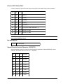
The following is an example of an Alpha STEPMASK containing two linked subfields with a leading
space (represented by an underscore):
Example 3:
STEPMASK
STARTDATA
Results
Value
_L01
_CAA
Description
Two linked subfields
_CAB First printing
_CAC Second printing
| etc.
_CZZ
ACAA
Note: Symbols rather than values would be shown for bar codes in examples 1 and 2. The
leading space in example 3 is not relevant to bar coding.
Chapter 3. Forms and Logo Generation
3-8
Incremental Alphanumeric Fixed Data Fields Command : ALPHA
This Alpha command is a modified version of the standard Alpha command. Do not use it as a substitute for standard alphanumeric command; use it only to automatically increment fixed data alphanumeric fields. Refer to standard Alpha command instructions for parameters not covered below. Also,
see Incrementing Alphanumeric Data for a detailed explanation of the STEPMASK and STARTDATA
parameters.
Incremental Alphanumeric Fixed Data Fields Command Syntax:
ALPHA<LF>
[R[D];][E;][Cn;]I;[DIR;]SR;SC;VE;HE;[idir]<LF>
STEPMASK;[RPTnnn;][RSTnnn;](D)STARTDATA(D)<LF>
STOP<LF>
Incremental Alphanumeric Fixed Data Fields Parameters:
I
Increment: Identifies the Alpha command as the Incremental Alphanumeric
Fixed Data Fields command.
idir
Increment Direction (default is to increment): An optional parameter used to
specify the arithmetic effect of the step on the data field. Enter “+” (or leave
blank) to increment (add step amount to) or enter “-” to decrement (subtract
step amount from) the data field.
STEPMASK
Specifies the increment amount (step), data field length, and mask to control
incrementing. Refer to Incrementing Alphanumeric Data for details.
STARTDATA
The starting value of alphanumeric data field to be incremented. The number
of STARTDATA characters must be equal to or less than the number of
characters in the STEPMASK parameter. STARTDATA text must be enclosed within the standard delimiters (commonly quote marks); e.g.,
“123ABC001”. Refer to the Incrementing Alphanumeric Data for details.
RPTnnn
Repeat Count (default is 1; i.e., increment with each printing): An optional
parameter used to specify the number of times to repeat a field value before
incrementing it. This feature is useful for printing multiple copies of a form
(such as a label) before changing the data field. To use this option, enter RPT
and replace nnn with the repeat count (1 to 65535).
RSTnnn
Reset Count (default is zero; no reset): An optional parameter used to specify
the number of times to print an incremented field (on one or more forms)
before resetting it to its starting value. This feature is useful if the data field
consists of levels of subfields; e.g., job/phase/item number generation. The
item number can be generated, reset, and then the phase incremented, etc.
To use this option, enter RST and replace nnn with the reset count (1 to
65,535).
GEK-89149A IGP Programmer’s Manual
3-9
Example: Increment and decrement a STARTDATA value containing linked subfields, and increment a
STARTDATA value containing two unlinked subfields.
Incremental Alphanumeric Fixed Data Fields Command Programming Example:
~CREATE;COUNT;1
ALPHA
I;1;10;0;0
000LLL001;”123ABC995"
I;1;25;0;0;000LLL001;”123ABC001"
I;1;40;0;0
001XXX001;”ABC999ZZV”
STOP
END
~EXECUTE;COUNT;10
/create a one-line form
/increment
/two linked subfields
/decrement
/two linked subfields
/increment
/two unlinked subfields
/print 10 times
~NORMAL
Print Sample
Incremental Alphanumeric Dynamic Data Fields Command : ALPHA
This Alpha command is a modified version of the standard Alpha command. Do not use it as a substitute for standard alphanumeric command; use it only to automatically increment alphanumeric dynamic data fields. Refer to standard Alpha command instructions for parameters not covered below.
Use this Alpha command to specify the position and size of the incremental dynamic data field under
the create form mode. The STEPMASK and STARTDATA parameters are entered in the execute
command under the execute forms mode. The starting data for both standard and incremental dynamic data fields can be changed without changing the form definition program. You can change the
incremental parameters for a new print job without changing the form definition program.
Incremental Alphanumeric Dynamic Data Fields Command Syntax:
ALPHA<LF>
[R[D];][E;][Cn;][IAFn;L;[DIR;]SR;SC;VE;HE;<LF>
STOP<LF>
Chapter 3. Forms and Logo Generation
3-10
Incremental Alphanumeric Dynamic Data Field Parameters (Continued):
The following Alpha parameters are unique to the Incremental Alphanumeric Dynamic Data Field
command. These parameters must be used to enable the dynamic entry of STEPMASK and
STARTDATA parameters during the Execute Forms Mode.
IAFn
Increment Alpha Field: Identifies the Alpha command as the Incremental
Alphanumeric Dynamic Data Fields command. The n parameter numbers the
data field for form location. Enter IAF and replace n with a number (1 to 255).
The SR (Starting Row) and SC (Starting Column) parameters entered in the
standard Alpha command specify the exact location of this data field number
on the form.
L
Length: Enter a number (1 to 226) to specify the field length for STARTDATA.
The number of characters dynamically entered for the STARTDATA parameter must be equal to or less than the value entered for L. Refer to the
Execute Incremental Dynamic Data section for details.
Example: Set up several fields to be dynamically entered and printed under the Execute Mode.
Incremental Alphanumeric Dynamic Data Fields Command Programming Example:
ALPHA
AF1;8;9;5;0;0
AF2;26;13;5;0;0
AF3;8;16;5;0;0
AF4;10;16;28;0;0
STOP
/9-character field; print at SR 9, SC
/26-character field; print at SR 13, SC 5
/8-character field; print at SR 16, SC 5
/10-character field; print at SR 16, SC 28
Note: Refer to Execute Dynamic Alphanumeric Data for print sample.
Duplicating Incremental Alphanumeric (or Bar Code) Fields
The Horizontal Duplication (HDUP) and Vertical Duplication (VDUP) commands explained later in this
chapter can be used to duplicate incremental alphanumerics or bar codes. When these commands are
used to duplicate fixed or dynamic data, fields are incremented in a left-to-right, top-to-bottom order.
The example below illustrates duplicated incremental fields with HDUP=3 (3 across) and VDUP=2 (2
down):
STEPMASK
STARTDATA
Results
Value
01
AA
Description
Increment alpha field
AA AB AC
AD AE AF
Form 0
AG AH AI
AJ AK AL
Form 1
Note: Spacing is determined by the HDUP and VDUP commands. Results shown for bar codes
would be actual bar code symbols as opposed to the letters.
GEK-89149A IGP Programmer’s Manual
3-11
Box Command : BOX
Boxes can be created using the Box command sequence. Parameters are used to define the starting
row and column (upper left corner) and ending row and column (lower right corner) positions. Line
thickness, size, and position are also user defined. Single, multiple, and overlapping boxes can be
printed in vertical/horizontal orientation.
BOX Command Syntax:
BOX<LF>
LT;SR;SC;ER;EC<LF>
STOP<LF>
BOX Parameters:
BOX
Boxes extend down and to the right from the starting row and column position
(defined by the SR and SC parameters).
LT
Line Thickness: This parameter specifies the line thickness in dots. Enter a
value of 1 or greater for the number of dots.
SR
Starting Row: The SR value specifies the starting row of the box. Replace SR
with a numeric value (1 to one less than the length of the form). Character
row or dot row is determined by the Scale command or the CP.DP format.
SC
Starting Column: The SC value specifies the starting column of the box.
Replace SC with a numeric value (1 to one less than the width of the form).
Character column or dot column is determined by the Scale command or the
CP.DP format.
ER
Ending Row: The ER value specifies the ending row of the box. Replace ER
with a numeric value (2 through the last row of the form). ER must be greater
than SR. Character row or dot row is determined by the Scale command or
the CP.DP format.
EC
Ending Column: The EC value specifies the ending column of the box.
Replace EC with a numeric value (2 through the last column of the form). EC
must be greater than SC. Character column or dot column is determined by
the Scale command or the CP.DP format.
STOP
Stop terminates this command and causes the printer to wait for a new
command. If STOP is not entered, the printer will wait for another set of Box
command parameters.
Box Command Programming Example (Print three concentric boxes):
~CREATE;3BOXES
BOX
3;35;25;40;50
2;36;26;39;49
1;37;27;38;48
STOP
END
~EXECUTE;3BOXES
/create form for box example
/large box; 3-dot border
/middle; 2-dot border
/small; 1-dot border
/terminate Box command
/terminate Create Mode
/print box example
~NORMAL
/return to Normal Mode
Chapter 3. Forms and Logo Generation
3-12
Print Sample
Corner Command : CORNER
Corners are created using the Corner command sequence. Parameters define the starting row and
column (upper left corner) and ending row and column (lower right corner) positions. Line thickness
and arm lengths are also user-defined. The four corners are printed in vertical/horizontal orientation.
Variable rotation of corners is not provided.
CORNER Command Syntax:
CORNER<LF>
LT;SR;SC;ER;EC;VL;HL<LF>
STOP<LF>
CORNER Parameters:
CORNER
The Corner command. Corners will be extended down and to the right from
the starting row and column position (defined by the SR and SC parameters).
LT
Line Thickness: This parameter specifies the line thickness, measured in
dots. Enter a value (1 or greater) for the number of dots.
SR
Starting Row: The SR value specifies the starting row of the corner. Replace
SR with a numeric value (1 to one less than the length of the form). Character
row or dot row is determined by the Scale command or the CP.DP format.
SC
Starting Column: The SC value specifies the starting column of the corner.
Replace SC with a numeric value (1 to one less than the width of the form).
Character column or dot column is determined by the Scale command or the
CP.DP format.
ER
Ending Row: The ER value specifies the ending row of the corner. Replace
ER with a numeric value (2 through the last row of the form). ER must be
greater than SR. Character row or dot row is determined by the Scale command or the CP.DP format.
EC
Ending Column: The EC value specifies the ending column of the corner.
Replace EC with a numeric value (2 through the last column of the form). EC
must be greater than SC. Character column or dot column is determined by
the Scale command or the CP.DP format.
GEK-89149A IGP Programmer’s Manual
3-13
CORNER Parameters (Continued):
VL
Vertical Length: The VL value specifies the length of the vertical arm of each
of the four corners. Replace VL with a numeric value (1 or greater). Character
or dot column format is determined by the Scale command or the CP.DP
format.
HL
Horizontal Length: The HL value specifies the length of the horizontal arm of
each corner in the set. Replace HL with a numeric value (1 or greater).
Character or dot column format is determined by the Scale command or the
CP.DP format.
STOP
Stop terminates this command and causes the printer to wait for a new
command. If STOP is not entered, the printer will wait for another set of
Corner command parameters.
Programming Example (Create a set of four corners):
~CREATE;CORNERS
CORNER
3;25;25;35;50;3;5
STOP
END
~EXECUTE;CORNERS
/create form for corners
/Corner thickness is 3 dots,
/3 rows high and 5 columns wide
/terminate Corner command
/terminate Create Mode
/print corners
~NORMAL
/return to Normal Mode
Print Sample
End Command : END
The End command is used to terminate the current mode of operation. It must be used before entering
a new mode command (Normal, Create, Logo, or Execute). In addition to terminating the current
mode, the End command initiates the following printer functions:
•
Program errors are cleared out.
•
Error-free sections of the current form program are stored.
•
SmartGraphics returns to the Normal (default) mode.
Note: The Debug debug slash (/) included in the Create command will result in the printing of
any applicable error messages.
Chapter 3. Forms and Logo Generation
3-14
END Command Syntax:
END<LF>
END Parameters:
END
The End command is used to terminate the current mode of operation before
issuing a new mode command.
For an example, refer to the example for the CORNER command.
Form Length : LFORM6 / LFORM8
Two commands are provided for setting the form length to a specified number of lines per form. Form
length can be set in 6 or 8 lpi (lines per inch) values. The two Form Length commands are:
Form Length Command Syntax:
LFORM6;nnnn<LF> or LFORM8;nnnn<LF>
Form Length Parameters:
LFORM6
The Form Length command for 6 lpi forms.
LFORM8
The Form Length command for 8 lpi forms.
nnnn
Specifies the forms length in total number of lines allowed per form. Replace
nnnn with the desired the number of lines:
1 - 5461 lines for 6 lpi forms;
1 - 7281 lines for 8 lpi forms.
A value that exceeds the maximum number of lines will result in an error
message.
Programming Example (Set a form length of 11" at 8 lpi):
LFORM8;88
Note: LFORM commands affect printed text only, not the printer emulation setting for lpi. The
LFORM6 and LFORM8 commands are the equivalent of the printer set to “data processing
mode”; 12 dot rows per line at 6 lpi or 9 dot rows at 8 lpi.
Horizontal Duplication Command : HDUP
This command is used to duplicate (repeat) form elements. It specifies the number of times the
elements are to be duplicated horizontally as well as the spacing between each duplication. The
command for the elements to be duplicated is placed after the HDUP command.
The HDUP command can also be used to modify incremental data output (refer to Duplicating Incremental Alphanumeric Data).
HDUP Command Syntax:
HDUP;DN;OF<LF>
(Elements to be Duplicated)
HDUP;OFF<LF>
GEK-89149A IGP Programmer’s Manual
3-15
HDUP Parameters:
HDUP
The Horizontal Duplication command.
DN
Duplication Number: The DN value specifies the number of times the entered
form elements will be repeated horizontally. Replace DN with a numeric value
(1 to 255).
OF
Offset (starting column to starting column): The OF value specifies the
horizontal spacing between each duplication of the form elements. Replace
OF with a number based on dot or character columns as determined by the
Scale command or the CP.DP format.
HDUP;OFF
Terminates the Horizontal Duplication command. If not entered, the printer
waits for another form element to be specified. A variety of element types can
be specified for duplication within one duplication command.
Programming Example (Duplicate staggered vertical lines to create a border effect):
~CREATE;BORDER
HDUP;5;9
VERT
1;5;9;10
1;6;8;10
1;7;7;9
1;8;6;8
1;9;5;7
1;10;6;8
1;11;7;9
1;12;8;10
1;13;9;10
STOP
HDUP;OFF
END
~EXECUTE;BORDER
/terminate Vertical Line command
/terminate Horizontal Duplication
/terminate Create Mode
/print zigzag lines
~NORMAL
/return to Normal Mode
/repeat 5 times with 9-column offset
/Vertical Line command
/line thickness=1; column 5; SR=9; ER=10
Print Sample
Chapter 3. Forms and Logo Generation
3-16
Horizontal Lines Command : HORZ
This command is used to create a horizontal line. Line thickness, position, and length are user specified. The command syntax is as follows:
HORZ Command Syntax:
HORZ<LF>
LT;R;SC;EC<LF>
STOP<LF>
HORZ Parameters:
HORZ
The Horizontal Line command.
LT
Line Thickness: The LT parameter specifies the line thickness in terms of
dots. Replace LT with a numeric value (1 or greater) to indicate the number of
dots. Line thickness extends downward from the starting row.
R
Row: The R parameter specifies the row where the horizontal line will be
drawn. Replace R with a row value (1 to one less than the length of the form).
Character row or dot row is determined by the Scale command or the CP.DP
format.
SC
Starting Column: The SC value specifies the starting column of horizontal
line. Replace SC with a numeric value (1 to one less than the width of the
form). Character column or dot column is determined by the Scale command
or the CP.DP format.
EC
Ending Column: The EC value specifies the ending column of the horizontal
line. Replace EC with a numeric value (2 to the last column of the form). EC
must be greater than SC. Character column or dot column is determined by
the Scale command or the CP.DP format.
STOP
Stop terminates this command and causes the printer to wait for a new
command. If STOP is not entered, the printer will wait for another set of
Horizontal Line command parameters.
Programming Example (Create two horizontal lines of different thickness):
~CREATE;LINES
HORZ
1;25;25;50
2;25.6;25;50
3;26;25;50
STOP
END
~EXECUTE;LINES
/line thickness is 1 dot
/line thickness is 2 dots;
/CP.DP format used
/line thickness is 3 dots
~NORMAL
Print Sample
GEK-89149A IGP Programmer’s Manual
3-17
Logo Call Command : LOGO
A logo is actually created under the Create Logo Mode command. The Logo Call command selects a
previously defined logo and positions it on the form.
LOGO Command Syntax:
LOGO<LF>
SR;SC;LOGO NAME<LF>
STOP<LF>
LOGO Parameters:
LOGO
The Logo Call command.
SR
Starting Row: The SR value specifies the starting row of the logo (based on
the upper left corner of the logo grid). Replace SR with a numeric value (1 to
one less than the length of the form). Character row or dot row is determined
by the Scale command or the CP.DP format.
SC
Starting Column: The SC value specifies the starting column of the logo
(based on the upper left corner of the logo grid). Replace SC with a numeric
value (1 to one less than the width of the form). Character column or dot
column is determined by the Scale command or the CP.DP format.
LOGO NAME
Name given the logo when created. Replace LOGO NAME with the desired
logo name (up to 8 characters); this entry must match the logo name stored in
the printer directory.
STOP
Stop terminates this command and causes the printer to wait for a new
command. If STOP is not entered, the printer will wait for another set of Logo
Call command parameters.
Example: Call a previously defined logo named NUT and print the logo two times (see logo definition
under Create Logo command in this chapter).
LOGO Programming Example:
~CREATE;NUTZ;0
LOGO
15;15;NUT
15;27;NUT
STOP
END
~EXECUTE;NUTZ
/create form for nuts
/print at SR 15; SC 15
/print at SR 15; SC 27
/terminate Logo command
/terminate Create Mode
/print nuts
~NORMAL
/return to Normal Mode
Chapter 3. Forms and Logo Generation
3-18
Print Sample
Page Number Command : PAGE
This command specifies the positioning of the page number on the form. In order for the printer to
automatically increment page numbers on successive copies of the form, the starting page number
must be defined with the Execute commands optional parameter, Page n. See the EXECUTE
command’s description in this chapter.
PAGE Command Syntax
PAGE;SR;SC<LF>
PAGE Parameters:
PAGE
The Page Number command.
SR
Starting Row: The SR value specifies the starting row of the page number.
Replace SR with a numeric value (1 to one less than the length of the form).
Character row or dot row is determined by the Scale command or the CP.DP
format.
SC
Starting Column: The SC value specifies the starting column of the page
number. Replace SC with a numeric value (1 to one less than the width of the
form). Character column or dot column is determined by the Scale command
or the CP.DP format.
GEK-89149A IGP Programmer’s Manual
3-19
Programming Example (Position the page number at row 62 and column 42):
~CREATE;PAGENUM
PAGE;62;42
ALPHA
6.8;20;0;0;"THIS DEMONSTRATES PAGE NUMBERING"
STOP
END
~EXECUTE;PAGENUM
~NORMAL
Reverse Print Command : REVERSE
This command specifies an area of the form for reverse printing (white on black). Two densities of
black background are available: the standard density background uses odd dot plotting; the higher
density background uses both odd and even dot plotting. Use the denser background when more
contrast is desired.
Form elements within the reverse print field are printed white on black. Reverse print can be used for
the following:
•
Standard (10 cpi) and expanded characters.
•
Rotated standard (10 cpi) and expanded characters.
•
Logos and all form elements (lines, boxes, etc.).
The Reverse Print feature is not provided for bar codes and compressed print. The command syntax
is as follows:
REVERSE Command Syntax
REVERSE<LF>
[DARK;]SR;SC;ER;EC<LF>
STOP<LF>
REVERSE Parameters:
REVERSE
The Reverse Printing command.
DARK
An optional parameter used to designate denser black background (odd and
even dot plotting). The standard or default is lighter background (odd dot
plotting only). Enter DARK if you wish to select the denser background.
SR
Starting Row: The SR value specifies the starting row of the reverse print
field. Replace SR with a numeric value (1 to one less than the length of the
form). Character row or dot row is determined by the Scale command or the
CP.DP format.
SC
Starting Column: The SC value specifies the starting column of the reverse
print field. Replace SC with a numeric value (1 to one less than the width of
the form). Character column or dot column is determined by the Scale
command or the CP.DP format.
Chapter 3. Forms and Logo Generation
3-20
REVERSE Parameters (Continued):
ER
Ending Row: The ER value specifies the ending row of the reverse print field.
Replace ER with a numeric value (2 through the last row of the form). ER
must be greater than SR. Character row or dot row is determined by the
Scale command or the CP.DP format.
EC
Ending Column: The EC value specifies the ending column of the reverse
print field. Replace EC with a numeric value (2 through the last column of the
form). EC must be greater than SC. Character column or dot column is
determined by the Scale command or the CP.DP format.
STOP
Stop terminates this command and causes the printer to wait for a new
command. If STOP is not entered, the printer will wait for another set of
Reverse Print command parameters.
Programming Example (Set page header bar for reverse print - high density):
~CREATE;HEADER
REVERSE
6;15;8;60
/print at SR 6, SC 15, ER 8, EC 60
STOP
ALPHA
6.8;20;0;0;”TEXT IN HEADER AREA PRINTS REVERSED”
STOP
END
~EXECUTE;HEADER
~NORMAL
Print Sample
Scale Command : SCALE
The Scale command determines data positioning by specifying the scale factor to be used; either dot
scale or character scale. Certain commands position data by parameters that specify starting row and
column (SR and SC) and ending row and column (ER and EC). If the Scale command specifies dot
scale, then data will be positioned at the dot row and dot column specified by the applicable command
parameter. Otherwise, data will be positioned at the character row and character column.
A standard 8 1/2 x 11 inch form (at the default setting, 6 lpi and 10 cpi) contains the following number
of rows and columns:
Scale
# Rows
# Columns
Character
Dot
66
792
80
720
Either of the Scale commands can be issued at any time during forms creation. Scale commands
become active at the point of insertion. Prior elements are printed at the former scale; elements that
follow a change will be printed at the scale designated.
GEK-89149A IGP Programmer’s Manual
3-21
The Scale command does not affect the size of the printed data itself. Text printed at 6 lpi and 10 cpi
will continue to be printed at 6 lpi and 10 cpi after a Scale change. Just the position of the data will be
affected.
SCALE Command Syntax:
SCALE;DOT<LF>
-orSCALE;CHAR[;LPI;CPI] <LF>
SCALE Parameters:
SCALE
The Scale command.
DOT
Specifies the dot scale.
CHAR
Specifies the character scale.
LPI
Lines Per Inch (default is 6 lpi): An optional vertical line spacing parameter for
character scaling. Valid entries are 6, 8, 9 or 10.
CPI
Characters Per Inch (default is 10 cpi): An optional horizontal pitch parameter
for character scaling. Valid entries are 10, 13, 15, and 17.
Programming Example (Set character scale at 8 lpi and 17 cpi):
SCALE;CHAR;8;17
Scale and Character/Dot Position Format Command: CP.DP command CP.DP
Note: Scale has no effect on the CP.DP Format command; each command is independent of
the other.
The CP.DP format is most commonly used to adjust starting and ending print Position data positions.
When printing alphanumeric data (text) on a form, it is normal to have a line or box occupying the
same position as the intended text. To avoid overprinting, CP.DP format values are entered to immediately precede the starting row (SR) and/or starting column (SC) parameters, thus offsetting the text.
The CP value indicates the Cell position cell position; the DP value indicates the Dot position dot
position with that cell. When printing at 6 lpi and 10 cpi, each character position or cell is 12 dot rows
high by 6 dot columns wide. A CP.DP format preceding an SC (starting column) dictates the starting
dot position down in the cell; a CP.DP value preceding an SR (starting row) dictates the starting dot
position to the right within the cell.
Chapter 3. Forms and Logo Generation
3-22
In the Execute LABEL example shown later in this chapter, the top line of a box prints at SC 2 and SR
6. In order to drop the title (“CATALOG NO.”) below this line, the subsequent ALPHA command calls
for print at starting row CP.DP position 6.6. Figure 3-1 is a graphic illustration of the effect of this
CP.DP positioning.
2.0
3.0
4.0
DP
6.0
0
7.0
Figure 3-1: Character Cell Grid (6 x 12 dots). X represents upper left box corner; 0 is the starting dot
position for text.
The Execute LABEL example utilizes CP.DP positioning for both SR and SC parameters.
Vertical Duplication Command: VDUP
This command is used to duplicate (repeat) form elements. It specifies the number of times the
elements are to be duplicated vertically, as well as the spacing between each duplication. The command for the elements to be duplicated is placed after the VDUP command. The VDUP command can
also be used to modify incremental data output (refer to Duplicating Incremental Alphanumeric Data).
VDUP Command Syntax:
VDUP;DN;OF<LF>
(elements to be duplicated)
VDUP;OFF<LF>
VDUP Parameters:
VDUP
The Vertical Duplication command.
DN
Duplication Number: The DN value specifies the number of times the entered
form elements will be repeated horizontally. Replace DN with a numeric value
(1 to 255).
OF
Offset (starting column to starting column): The OF value specifies the
vertical spacing between each duplication of the form elements. Replace OF
with a number based on dot or character columns as determined by the Scale
command or the CP.DP format.
GEK-89149A IGP Programmer’s Manual
3-23
VDUP Parameters (Continued):
VDUP;OFF
Terminates the Vertical Duplication command. If not entered, the printer waits
for another form element to be specified. A variety of element types can be
specified for duplication within one duplication command.
Programming Example (Create three columns, four blank lines each):
~CREATE;BLANKS
VDUP;4;2
HORZ
1;25;10;20
1;25;25;35
1;25;40;50
STOP
VDUP;OFF
END
~EXECUTE;BLANKS
/repeat 4 times with 2-column offset
/Horizontal Line command
/print at row 25, SC 10, EC 20
/terminate Horizontal Line command
/terminate Vertical Duplication
/print form
~NORMAL
/return to Normal Mode
Print Sample
Note: Position of print sample does not necessarily reflect actual print position.
Vertical Lines Command : VERT
This command is used to create a vertical line. Line thickness, position, and length are user specified.
The command syntax is as follows:
VERT Command Syntax:
VERT<LF>
LT;C;SR;ER<LF>
STOP<LF>
VERT Parameters:
VERT
The Vertical Line command.
LT
Line Thickness: The LT parameter specifies the line thickness in terms of
dots. Replace LT with a numeric value (1 or greater) to indicate the number of
dots. Line thickness extends to the right from the starting column.
Chapter 3. Forms and Logo Generation
3-24
VERT Parameters (Continued):
C
Column: The C parameter specifies the column at which the vertical line will
be drawn. Replace C with a value (1 to one less than the width of the form).
Character row or dot row is determined by the Scale command or the CP.DP
format.
SR
Starting Row: The SR value specifies the starting row of the vertical line.
Replace SR with a numeric value (1 to one less than the length of the form).
Character column or dot column is determined by the Scale command or the
CP.DP format.
ER
Ending Row: The ER value specifies the ending row of the vertical line.
Replace ER with a value (2 to the last row of the form). ER must be greater
than SR. Character column or dot column is determined by the Scale command or the CP.DP format.
STOP
Stop terminates this command and causes the printer to wait for a new
command. If STOP is not entered, the printer will wait for another set of
Vertical Line command parameters.
Programming Example (Create three columns, four blank lines each):
~CREATE;3LINES
VERT
3;10;50;55
2;15;50;55
1;20;50;55
STOP
END
~EXECUTE;3LINES
~NORMAL
/line thickness is 3 dots
/line thickness is 2 dots
/line thickness is 1 dot
/print form
/return to Normal Mode
Print Sample
GEK-89149A IGP Programmer’s Manual
3-25
Create Logo Mode : LOGO
Use this command to design and create a logo. You must define the overall grid size in dots, then
define the specific dot and/or series of dots to be printed in each grid row. The upper left corner of the
logo grid is the starting row (SR) and starting column (SC) parameters for the Logo Call command.
A logo grid contains 72 dots per inch vertically and 60 dots per inch horizontally. The largest logo
allowed is 252 dot rows high (3.5 inches) and 240 dot columns wide (4 inches). A maximum of 16
number logos can be created and stored in memory.
Note: Do not specify grid dimensions substantially larger than required by the logo; you will
waste SmartGraphics memory which will restrict other features that you may want to use.
LOGO Command Syntax:
<SFCC>LOGO;LOGO NAME;VL;HL<LF>
RN;D;D1-D2;D<LF>
END<LF>
LOGO Parameters:
<SFCC>
Represents the Special Function Control Character. Unless changed by
strapping option, enter ~ (default).
LOGO
The Logo command.
LOGO NAME
Defines the name of the logo being created. The logo name may contain a
maximum of eight alphanumeric characters. No spaces, semicolons, slashes
or the SFCC are allowed. Be careful: An existing logo with the same name will
be overwritten and replaced by the new logo. Any future editing, executing, or
deleting of the logo (e.g., Delete Logo or Logo Call commands) must be done
using the assigned name. A maximum of 16 logos can be stored in printer
memory.
VL
Vertical Length (252 maximum): The VL value specifies the overall vertical
length of the logo grid in dot rows. Replace VL with a sufficient numeric value
(not to exceed 252). Remember, oversizing wastes memory.
HL
Horizontal Length (240 maximum): The HL value specifies the overall horizontal length of the logo grid in dot rows. Replace HL with a sufficient numeric
value (not to exceed 240). Remember, oversizing wastes memory.
RN
Row Number: The RN value specifies the row number for this row of dots in
the logo grid. Use a separate command line for each row number. Rows are
numbered (1 to 252 maximum) from the top down.
D
Dot (single): D specifies a single dot position to be printed within a row. More
than one entry per line is allowed. Enter each dot number desired, separating
each entry with a semicolon. Dots are numbered (1 to 240 maximum) from
left to right.
Chapter 3. Forms and Logo Generation
3-26
LOGO Parameters (Continued):
D1-D2
Dots (series): Use these parameters to specify a range or series of dot
positions (left to right) to be printed within the row. The starting (D1) and the
ending (D2) positions will also be printed. Single dots and a series of dots can
be combined in the same command line. Enter the desired series (1-240,
minimum and maximum), separating each series with a semicolon.
END
END terminates Create Logo Mode.
Programming Example (Create a logo to resemble a hexagonal nut approximately 1 x 1"):
~LOGO;NUT;72;60
1;17-44
2;16;29;45
3;15;28;46
4;14;27;47
5;13;26;48
6;12;25;49
7;11;24;50
8;10;23;51
9;9;22;52
10;8;21;53
11;7;20;54
12;6;19;55
13;5;18;56
14;4;17;57
15;3;16;58
16;2;15;59
17;1-14;36-38;60
18;1;14;34-40;60
19;1;14;32-42;60
20;1;14;31;34-43;60
21;1;14;30;36-44;60
22;1;14;29;38-44;60
23;1;14;28;39-45;60
24;1;14;28;39-45;60
25;1;14;27;40-46;60
26;1;14;27;40-46;60
27;1;14;27;41-46;60
28;1;14;27;41-46;60
29;1;14;27;41-46;60
30;1;14;27;41-46;60
31;1;14;27;40-46;60
32;1;14;27;40-46;60
33;1;14;28;39-45;60
34;1;14;28;39-45;60
35;1;14;29;38-44;60
36;1;14;30;36-44;60
37;1;14;31;34-43;60
38;1;14;32-42;60
39;1;14;34-40;60
40;1-14;36-38;60
41;2-15;59
42;3-16;58
43;4-17;57
44;5-18;56
GEK-89149A IGP Programmer’s Manual
/logo grid set at 72 x 60
/row number; dots to be printed
3-27
Create Logo Mode Programming Example (Continued):
45;6-19;55
46;7-20;54
47;8-21;53
48;9-22;52
49;10-23;51
50;11-24;50
51;12-25;49
52;13-26;48
53;14-27;47
54;15-28;46
55;16-29;45
56;17-44
END
~CREATE;1NUT;0
LOGO
15;15;NUT
STOP
END
~EXECUTE;1NUT
/terminate Logo command
/create form for nut logo
/logo call command; note lack of SFCC
/print at SR 15; SC 15
/terminate Logo command
/terminate Create Mode
/print nut logo
~NORMAL
/return to Normal Mode
Print Sample
Execute Form Mode Command : EXECUTE
The Execute Form Mode command is used to print a form. This command can be used only after the
form has been created under the Create Form Mode.
The Execute command provides:
•
Optional page numbering
•
Optional form count for printing multiple copies
•
Print format commands (e.g., lpi, elongation, and plot mode)
•
Compressed and expanded print commands
•
Vertical spacing commands
•
Alternate character set selection
Chapter 3. Forms and Logo Generation
3-28
Forms can be printed with static (fixed) and/or variable data entry. The following data can be input
during the Execute Form Mode:
•
Page numbers
•
Alphanumeric dynamic and overlay data fields
•
Bar code dynamic data fields
Variable data entry must have been established by the Alpha and bar code command parameters
during the Create Form Mode. Additional Execute parameters are provided for printing such alphanumeric and bar code data on the form.
With respect to incremental data, there are two formats of the Execute command: a standard version
that executes non-incremental or fixed incremental data, and another one to execute incremental
dynamic data (refer to Execute Incremental Data).
EXECUTE Command Syntax:
<SFCC>EXECUTE;FORM NAME[;PAGE n][;FC]<LF>
[Overlay Data]<LF>
[<SFCC>AFn;(D)ASCII TEXT(D)]<LF>
[<SFCC>BFn;(D)DATA FIELD(D)]<LF>
<SFCC>NORMAL<LF>
EXECUTE Parameters:
<SFCC>
The Special Funtion Control Character.
EXECUTE
The Execute Form Mode command.
FORM NAME
Name given the form when created. Replace FORM NAME with the desired
form name (up to 8 characters); this entry must match the form name stored
in the printer directory.
PAGE n
Optional pagination command: Enter PAGE, a space, and then the starting
Page number page number (between 0 and 99999999). A maximum of eight
digits is allowed; the next page after 999999999 is 00000000. Page number
print position is determined by the Page Number command under the Create
Form Mode.
FC
Form Count (default is 1): An optional parameter used to specify the number
of copies of the form to be printed. Replace FC with the desired number (2 or
greater). SmartGraphics automatically returns to the Normal Mode after the
last page is printed, do not use the FC parameter if dynamic or overlay data is
to be entered.
Overlay Data
Overlay data can be entered as part of the Execute command. If used, this
line can be replaced with multiple lines of overlay data. Refer to the Execute
Overlay Data instructions that follow the syntax explanation.
AFn;(D)ASCII TEXT(D) The Execute Dynamic Alphanumeric Data Command. Refer to the Execute
Dynamic Alphanumeric Data instructions that follow the syntax explanation.
GEK-89149A IGP Programmer’s Manual
3-29
EXECUTE Parameters (Continued):
BFn;(D)ASCII TEXT(D) The Execute Dynamic Bar Code Data command. Refer to the Execute
Dynamic Bar Code Data instructions that follow the syntax explanation.
Normal
The Normal Mode command. This is not required if the FC parameter was
used. Enter the SFCC character and NORMAL to return to the Normal Mode.
This command must follow all other Execute commands to allow for variable
data entry (refer to the following instructions). A blank line must precede the
Normal command.
Programming Example (Create and print a 3 x 5" mailing label with company logo, name, and
address):
~CREATE;LABEL;216
/create 3" label form
HORZ
/Horizontal Line
2;1;2;33
1;1;35;39
1;2.4;33;36.2
1;4.3;33;36.2
1;5.8;35;39
STOP
CORNER
/Corner command
1;9;5;17;46;2;2
/line thickness 1
STOP
ALPHA
/Alpha command
2;2;2;2;”PRECISION PARTS”
/co. name and address
C15;3;14;0;0;”123 MAIN ST”
C15;4;12;0;0;”ANYWHERE, USA 54321"
C15;5;13;0;0;”(800) 555-1000"
10;7;0;0;”TO:”
STOP
LOGO
/logo previously defined
1;37;NUT
/print at SR 1, SC 37
STOP
END
/terminate Create Mode
~EXECUTE;LABEL
/print one form
~NORMAL
Chapter 3. Forms and Logo Generation
/return to Normal Mode
3-30
Print Sample
Note: Once created, LABEL forms can be printed by issuing the desired EXECUTE command
sequence (see the following Overlay example).
Execute Overlay Data : EXECUTE
Overlay data is a type of variable alphanumeric data that can be entered during the Execute Form
Mode. Imagine a form designed with blank areas yet to be filled in, and the overlay data as a transparency. The overlay text is entered in the exact position that fills in the blank areas when “overlaid” on
the form.
The positioning of overlay data is accomplished with physical line feeds and spaces. For example, if
the blank form area reserved for the customer name field begins at character row 12, column 20, you
can enter 12 line feeds, press the space bar 20 times, and type the company name as the overlay
data. Using this method, you can create an entire form as a page of overlay data.
Note: You must enter a form feed to separate each new page of overlay data.
Example: Supply customer name and address overlay data for the LABEL form (created in previous
Execute example).
EXECUTE Programming Example:
~EXECUTE;LABEL
ACME PRODUCTS, INC.
1000 BYRDS CIRCLE
MOHAVE, NM 98765
~NORMAL
GEK-89149A IGP Programmer’s Manual
/print one form
/insert 12 <LF>’s
/space over 20 times
/return to Normal Mode
3-31
Print Sample
Execute Dynamic Alphanumeric Data : EXECUTE
Dynamic alphanumeric data is a type of variable data that can be entered during the Execute Form
Mode. Unlike overlay data that is manually positioned when entered, dynamic data is located by
specifying the actual data and location on the form.
Dynamic data position is established using the AFn;L parameters of the Alpha command in the Create
Form Mode (refer to Alphanumeric Dynamic Data Fields Command). The data is input dynamically in
the identified location each time the form is printed under the Execute command.
Note: You must enter a form feed to separate each new page (i.e., the Execute command, the
dynamic fields and data, and the Normal command) of dynamic data.
Depending on the current mode status, all or part the following command syntax is required:
Execute Dynamic Alphanumeric Data Command Syntax:
<SFCC>EXECUTE;FORM NAME[;PAGE n]<LF>
<SFCC>AFn;(D)ASCII TEXT(D)<LF>
<SFCC>NORMAL<LF>
Execute Dynamic Alphanumeric Data Parameters:
<SFCC>
Represents the Special Function Control Character.
EXECUTE;FORM NAME
[;PAGE n]
The Execute Form Mode command and form name as previously
explained. This command line is not required if you are already in the
Execute Form Mode and the form has been called.
Note: The Form Count (FC) parameter cannot by used for dynamic data entry; however, the
optional page number parameter can be used.
Chapter 3. Forms and Logo Generation
3-32
Execute Dynamic Alphanumeric Data Parameters (Continued):
AFn
Alpha Field Identifier: The AF parameter identifies the dynamic data
field being entered. Enter AF and replace n with the same number
entered for the AFn;L parameter under the Alpha command during
the Create Form Mode.
D
Delimiter: Used to denote the start and finish of the alphanumeric
string. You may use any printable character other than a /, the SFCC,
or a character used within the string itself. Quotation marks (“) are
most commonly used to denote both ends of an alpha numeric string.
The delimiter is not printed.
ASCII TEXT
The alphanumeric string to be printed. Enter any of the standard
ASCII printable characters, except the character used as the delimiter
or D parameter. The data is printed on the form at the location
dictated by the n parameter reference. Print position is defined by the
SR and SC parameters entered under the Alpha command during the
Create Form Mode.
NORMAL
The Normal Mode command. After the last dynamic data command,
enter the SFCC and NORMAL to return to the Normal Mode. Enter an
<LF> (line terminator) to insert a blank line before the Normal command is entered.
You can repeat the AFn;(D)ASCII TEXT(D) sequence for every data field defined in the Create Form
Mode. The Execute Dynamic Bar Code Data command can also be combined in the same Execute
command sequence. Be sure to separate each page of dynamic data with a form feed.
Example: Create a shipping label that provides dynamic entry of these data fields: catalog number,
description, part number, and serial number.
Execute Dynamic Alphanumeric Data Programming Example:
~CREATE;LABEL2;216
/create 3" label form
HORZ
/Horizontal Line command
2;1;2;33
1;1;35;39
1;2.4;33;36.2
1;4.3;33;36.2
1;5.8;35;39
STOP
BOX
/Box command
2;6;2;17;47
/line thickness 2
STOP
HORZ
/Horizontal Line Command
1;11;2;47
1;14;2;47
STOP
VERT
/Vertical Line command
1;25;14;17
STOP
ALPHA
/Alpha command
2;2;2;2;”PRECISION PARTS”
/name and address
C15;3;14;0;0;”123 MAIN ST”
C15;4;12;0;0;”ANYWHERE, USA 54321"
C15;5;13;0;0;”(800) 555-1000"
6.6;3;0;0;”CATALOG NO:”
/box titles
GEK-89149A IGP Programmer’s Manual
3-33
Execute Dynamic Alphanumeric Data Programming Example (Continued):
11.6;3;0;0;”DESCRIPTION”
14.6;3;0;0;”PART NO.”
14.6;26;0;0;”SERIAL NO.”
AF1;8;9;5;0;0
AF2;26;13;5;0;0
AF3;8;16;5;0;0
AF4;10;16;28;0;0
STOP
LOGO
1;37;NUT
STOP
END
~EXECUTE;LABEL2
~AF1;”25-1046A”
~AF2;”WIDGET FASTENERS”
~AF3;”WGT-3492"
~AF4;”W98-600321"
/dynamic data: catalog no.
/description
/part number
/serial number
/logo previously defined
/print at SR 2, SC 37
/terminate Create Mode
/print one form
/dynamic entries: catalog no.
/description
/part number
/serial number
~NORMAL
Print sample
Execute Dynamic Bar Code Data : EXECUTE
Dynamic bar code data is a type of variable data that can be entered during the Execute Form Mode.
A command sequence defines the actual bar code data and its location on the form.
Bar code data position is established using the BFn parameter of the Bar Code command in the
Create Form Mode (refer to the applicable bar code command instructions). The bar code data is input
dynamically in the identified location each time the form is printed under the Execute command.
Note: You must enter a form feed to separate each new page (i.e., the Execute command, the
dynamic fields and data, and the Normal command) of bar code data.
Chapter 3. Forms and Logo Generation
3-34
Execute Dynamic Bar Code Data Command Syntax
<SFCC>EXECUTE;FORM NAME[;PAGE n]<LF>
<SFCC>BFn;(D)DATA FIELD(D)<LF>
<SFCC>NORMAL<LF>
Execute Dynamic Bar Code Data Parameters:
<SFCC>
Represents the Special Function Control Character.
EXECUTE;FORM NAME[;PAGE n]
The Execute Form Mode command and form name as
previously explained. This command line is not required if
you are already in the Execute Form Mode and the form has
been called.
Note: The Form Count (FC) parameter cannot by used for dynamic data entry; however, the
optional page number parameter can be used.
BFn
Bar Code Field Identifier: The BF parameter specifies a
dynamic bar code field and identifies the field being supplied
with data. Enter BF and replace n with the same number
entered for the BFn parameter under the bar code command
during the Create Form Mode.
D
Delimiter: Used to denote the start and finish of the alphanu
meric string . You may use any printable character other than
a /, the SFCC, or a character used within the string itself.
Quotation marks (“) are most commonly used to denote both
ends of an alphanumeric string. The delimiter itself is not
printed.
DATA FIELD
Enter the characters for the bar code data. The type of
characters allowed depends on the type of bar code used.
Refer to the applicable bar code Data Field instructions for
allowable types.
NORMAL
The Normal Mode command. After the last dynamic data
command, enter the SFCC and NORMAL to return to the
Normal Mode. Enter an <LF> (line terminator) to insert a
blank line before the Normal command is entered.
You can repeat the BFn;(D)DATA FIELD(D) sequence for every bar code field defined in the Create
Form Mode. The Execute Dynamic Alphanumeric Data command can also be combined in the same
Execute command sequence. Be sure to separate each page of dynamic data with a form feed.
Example: Add a bar code to the shipping label to represent the catalog number.
Note: Adding an element to the label means that the form must be redefined.
GEK-89149A IGP Programmer’s Manual
3-35
Execute Dynamic Bar Code Data Programming Example:
~CREATE;LABEL2;216
/create 3" label form
HORZ
/Horizontal Line command
2;1;2;33
1;1;35;39
1;2.4;33;36.2
1;4.3;33;36.2
1;5.8;35;39
STOP
BOX
/Box command
2;6;2;17;47
/line thickness 2
STOP
HORZ
/Horizontal Line command
1;11;2;47
1;14;2;47
STOP
VERT
/Vertical Line command
1;25;14;17
STOP
ALPHA
/Alpha command
2;2;2;2;”PRECISION PARTS”
/name and address
C15;3;14;0;0;”123 MAIN ST”
C15;4;12;0;0;”ANYWHERE, USA 54321"
C15;5;13;0;0;”(800) 555-1000"
6.6;3;0;0;”CATALOG NO:”
/box titles
11.6;3;0;0;”DESCRIPTION”
14.6;3;0;0;”PART NO.”
14.6;26;0;0;”SERIAL NO.”
AF1;8;9;5;0;0
/dynamic data: catalog no.
AF2;26;13;5;0;0
/description
AF3;8;16;5;0;0
/part number
AF4;10;16;28;0;0
/serial number
STOP
BARCODE
/Bar Code command
C3/9;BF1;7;25
/type and print position
STOP
LOGO
/logo previously defined
1;37;NUT
/print at SR 2, SC 37
STOP
END
/terminate Create Mode
~EXECUTE;LABEL2
/print one form
~AF1;”25-1046A”
/dynamic entries: catalog no.
~AF2;”WIDGET FASTENERS”
/description
~AF3;”WGT-3492"
/part number
~AF4;”W98-600321"
/serial number
~BF1;”25-1046A”
/bar code
~NORMAL
Chapter 3. Forms and Logo Generation
3-36
Print Sample
Supplying Incremental Dynamic Data
Incremental dynamic data fields are defined under the Create Form Mode refer to applicable Incremental Alpha or Bar Code commands. The incremental data itself is “dynamically” entered during the
Execute Form Mode. Corresponding incremental data fields must be supplied with the Execute
command; otherwise, dynamic data fields specified in the Create Form Mode will not be printed on the
form.
Incremental dynamic data, either alphanumeric or bar code data; is supplied at the top of the form
prior to any overlay data. It can be changed with each new batch of forms. The command formats for
supplying incremental alphanumeric and bar code dynamic data are basically the same.
Supplying Incremental Dynamic Data Command Syntax:
Incremental dynamic alphanumeric data:
<SFCC>IAFn;[idir]STEPMASK;[RPTnnn;][RSTnnn;](D)STARTDATA(D)
Incremental dynamic bar code data:
<SFCC>IBFn;[idir]STEPMASK;[RPTnnn;][RSTnnn;](D)STARTDATA(D)
Supplying Incremental Dynamic Data Parameters:
<SFCC>
The Special Function Control Character.
IAF
Incremental Alphanumeric Dynamic Data parameter.
IBF
Incremental Bar Code Dynamic Data parameter.
n
Field number identifier: The number of the dynamic data field as entered in
the Create Form Mode. Replace n with the same number entered for this field
in the AF or BF parameter. Refer to applicable Alpha or Bar Code command.
GEK-89149A IGP Programmer’s Manual
3-37
Supplying Incremental Dynamic Data Parameters (Continued):
idir
Increment Direction (default is to increment): An optional parameter used to
specify the arithmetic effect of the step on the data field. + (or leave blank) to
increment or - to decrement the data field.
STEPMASK
Specifies the increment amount (step), data field length, and mask to control
incrementing. Refer to Incrementing Alphanumeric Data or Incremental Bar
Code Data for details.
RPTnnn
Repeat Count (default is 1; i.e., increment with each printing): An optional
parameter used to specify the number of times to repeat a field value before
incrementing it. This feature is useful for printing multiple copies of a form
(such as a label) before changing the data field. To use this option, enter RPT
and replace nnn with the repeat count (1 to 65535).
RSTnnn
Reset Count (default is zero; no reset): An optional parameter used to specify
the number of times to print an incremented field (on one or more forms)
before resetting it to its starting value. This feature is useful if the data field
consists of levels of subfields; e.g., job/phase/item number generation. The
item number can be generated, reset, and then the phase incremented, etc.
To use this option, enter RST and replace nnn with the reset count (1 to
65,535).
STARTDATA
The starting value of alphanumeric data field to be incremented. The number
of STARTDATA characters must be equal to or less than the number of
characters in the STEPMASK parameter. If the number is less, the data will
be right justified with leading spaces (leading spaces are not provided for bar
code data). STARTDATA text must be enclosed within the standard delimiters
(commonly quote marks). Refer to the Incrementing Alphanumeric Data for
details.
Note: The type and quantity of characters allowed for bar code data depends on the type of bar
code used. Refer to the applicable bar code Data Field instructions.
Execute Incremental Dynamic Data : EXECUTE
The standard Execute command format is used to execute non-incremental as well as incremental
fixed data that is formatted under the Create Form Mode. The following Execute format is required for
executing incremental dynamic data (alphanumeric or bar code). It should be noted that the command
parameters differ from those required by the Execute command for non-incremental dynamic data.
You cannot issue both incremental and non-incremental dynamic data parameters in the same
Execute command.
The Execute Incremental Dynamic Data command is a modified version of the standard Execute
command.
Execute Incremental Dynamic Data Command Syntax:
<SFCC>EXECUTE;FORM NAME[;PAGE n];ICNTnnn[;IRSTnnn]
Chapter 3. Forms and Logo Generation
3-38
Execute Incremental Dynamic Data Parameters:
ICNTnnn
Incremental Form Count: The ICNT parameter specifies the number of forms
to be produced with the incremental fields automatically updated. To specify
the number of forms, enter ICNT and replace nnn with a numeric value (1 to
65,535).
IRSTnnn
Incremental Reset Count (default is 1): An optional parameter used to specify
the number of forms to produce before all incremental fields are reset to their
starting values. The IRST parameter can be used to separate the total
number of forms produced into multiple groups of identical copies. To use this
option, enter IRST and replace nnn with a numeric value (1 to 65,535) to
specify the reset count. In order for the reset to occur, the IRST value must
be less than the ICNT value.
Example: Print a sequential production number on a pre-existing label. The shipping label used in the
preceding examples (LABEL2) has been modified to include a box for production number. The modifications are shown in the program example that follows. A new label (LABEL3) must be created to
illustrate the incremental field feature. This 8-digit field will consist of date (month/day) followed by a 4digit incremental alphanumeric field. To achieve the final result, the labels are actually run twice; that
is, blank labels are loaded, the LABEL2 program is processed, then the printed labels are reloaded
and LABLEL3 is processed.
Executing Incremental Dynamic Data Programming Example:
~CREATE;LABEL2;216
HORZ
...
BOX
...
HORZ
...
VERT
1;33;11;14
1;25;14;17
...
ALPHA
...
1.6;3;0;0;”DESCRIPTION”
11.6;34;0;0;”PROD.NO.”
...
...
~EXECUTE;LABEL2;2
...
~NORMAL
/(modifications to LABLEL2)
/add down line for new box
/print box title
/print two labels
--- New Label --~CREATE;LABEL3;216
ALPHA
IAF1;8;13;36;0;0
STOP
END
~EXECUTE;LABEL3;2
~IAF1;XXXX0001;”0125AA99"
/Create new label
/incremental alpha field
/print two labels
/print production numbers
~NORMAL
GEK-89149A IGP Programmer’s Manual
3-39
Print Sample
Vertical Paper Motion
Paper movement is controlled either by the active printer emulation or by SmartGraphics. The emulation and the control panel are used during Normal Mode. Only SmartGraphics is used during Execute
Form Mode. Error messages or a drifting top of form can be prevented by observing the following
procedures:
1.
2.
3.
To compensate for the Skip Over Perf setting, reduce the optional Forms Length parameter
(FL) in the Create command by a corresponding amount. For example, if you want a 66 line
form (11 inches at 6 lpi) with a Skip Over Perf value of 6 lines (1 inch), enter an FL parameter
of 60 (60 lines equals 10 inches). This method of compensation will keep the top of form from
drifting.
Use the vertical line spacing command (LPI) to select the desired line spacing.
Use the Top of Form key on the control panel only when in the Normal Mode. Using this key in
other modes will cause the top of form to drift.
Paper must be loaded and adjusted to the desired top of form position before the Execute Form Mode
is executed. SmartGraphics does not track paper movement initiated through the control panel. The
use of control panel keys will cause the top of form maintained by SmartGraphics to differ from the top
of form maintained by the printer.
Chapter 3. Forms and Logo Generation
3-40
To re-sychronize SmartGraphics and the printer’s form settings, issue either a form feed or a NORMAL command to set SmartGraphics. Physically adjust the paper and press the control panel’s top of
form switch to set the print engine.
Fixed Record Length Utility Modes
Some software applications utilize “fixed record length” conventions where paper movement commands (carriage returns, line feeds, form feeds, etc.) are inserted to separate long data streams, and
pad characters are inserted to extend short data streams.
If SmartGraphics is used with a such an application, it may be necessary to ignore these paper
movement commands and pad characters. The SmartGraphics commands select Format and Ignore
Sequence are provided for this purpose. You can also use the Quiet command to pass all data
unchanged to the printer.
Select Format Command : SFON / SFOFF
Use this command as needed to ignore all host-generated paper movement commands (hex 00-0F)
during the Normal, Create Form, or Execute Form Mode. The SFON and SFOFF commands cannot
be used while Ignore Sequence is active. The command syntax is as follows:
SFON/SFOFF Command Syntax:
<SFCC>SFON
or
<SFCC>SFOFF
SFON/SFOFF Parameters:
<SFCC>
Represents the Special Function Control Character.
SFON
The Select Format On command.
SFOFF
Exits Select Format.
Note: Certain paper movement commands can be used only while in the Select Format Mode.
Use of these commands at any other time may result in a multiple error condition. Enter all
commands in uppercase.
<SFCC>CR
Sends a carriage return (hex 0D).
<SFCC>LF
Sends a line feed (hex 0A).
<SFCC>FF
Sends a form feed. (hex 0C).
GEK-89149A IGP Programmer’s Manual
3-41
Ignore Sequence Command : IGON / IGOFF
Use this command to ignore host-originated pad characters (refer to Fixed Record Length Utility
Mode). This command can be entered during Normal, Create Form, or Execute Form Modes. Once
IGON is issued, SmartGraphics will ignore all characters until it receives an IGOFF.
IGON/IGOFF Command Syntax:
<SFCC>IGON
or
<SFCC>IGOFF
IGON/IGOFF Parameters:
<SFCC>
Represents the Special Function Control Character.
IGON
Ignore Sequence On command
IGOFF
Exits Ignore Sequence.
Chapter 3. Forms and Logo Generation
3-42
CHAPTER 4. BAR CODES
A bar code is a graphic image that represents alphanumeric text characters. There are various types
of bar code formats recognized as industry standards. The type/style used is determined by the
application (e.g., publications, retail outlet, postal service, etc.)
Bar codes can be produced by issuing the applicable bar code command in Create Form Mode.
Depending on the type, bar code parameters include optional darker print, horizontal or vertical
orientation, magnification, variable height, and alphanumeric data field printing.
This chapter describes the following bar code types and commands:
Bar Code Type
Code 3/9
Code 128 - Subset B
Code 128 - Subset C
EAN 8
EAN 13
Interleaved 2 of 5
Universal Product Code - Version A
Universal Product Code - Version E
MSI
POSTNET
Command
C3/9
C128B
C128C
EAN8
EAN13
I-2/5
UPC-A
UPC-E
MSI
POSTNET
An overview of bar code types, terminology, and command conventions will be addressed first.
Bar Code Type Summary
This summary is presented in the following format:
Bar Code (command; data field length; code set)
Each code is followed by an abbreviated list of characteristics and options provided by that bar code
command.
Code 3/9 (C3/9; Variable; Alphanumeric)
•
Modulo-43 check digit field provided
•
Vertical positioning of the bar code symbol
•
Data can print above or below symbol
•
OCR-A and OCR-B font selection for human-readable data
•
Horizontal and vertical magnification
GEK-89149A IGP Programmer’s Manual
4-1
Code 128B (C128B; Variable; Alphanumeric)
•
Modulo-103 check digit field provided
•
Vertical positioning of the bar code symbol
•
Data printing above or below symbol
•
Automatic symbol compaction
•
Horizontal and vertical magnification
Code 128C (C128C; Variable; Numeric)
•
Modulo-103 check digit field provided
•
Vertical positioning of the bar code symbol
•
Data printing above or below symbol
•
Horizontal and vertical magnification
•
Nonnumeric or nonpaired numerics replaced with Code 128B symbols
EAN 8 (EAN8; Fixed 7 digits; Numeric)
•
Modulo-10 check digit field provided
•
No magnification option is allowed
•
Automatic printing of data in OCR-B
•
Height option from 0.4 to 9.9 inches
•
Suppress printable data field option
•
Optional 2-5 digit add-on data field
EAN 13 (EAN13; Fixed 12 digits, Numeric)
•
Modulo-10 check digit field provide
•
No magnification option is allowed
•
Automatic printing of data in OCR-B
•
Height option from 0.4 to 9.9 inches
•
Suppress printable data field option
•
Optional 2-5 digit add-on data field
•
Interleaved 2/5 (I-2/5; Variable, Numeric)
•
Modulo-10 check digit field provided
•
Vertical positioning of the bar code symbol
•
Data printed above or below symbol
•
Horizontal and vertical magnification
•
OCR-A and OCR-B font selection for human-readable data field
Chapter 4. Bar Codes
4-2
UPC-A (UPC-A; Fixed 11 digits, Numeric)
UPC-E (UPC-E; Fixed 11 digits, Numeric)
•
Modulo-10 check digit field provided
•
Vertical positioning of the bar code symbol
•
Automatic printing of data in OCR-B
•
No magnification allowed
•
Height option from 0.4 to 9.9 inches
•
Suppress printable data field option
•
Optional 2-5 digit add-on data field
MSI
•
Modulo 10, 11, or combination check digit provided
•
Vertical positioning of the bar code symbol
•
Data printed above or below symbol
•
Height option from 0.4 to 9.9 inches
•
Variable magnification option
POSTNET
Specific POSTNET bar code requirements can be obtained from Publication 25: “A Guide to Business
Mail Preparation” published by the U.S. Postal Service.
GEK-89149A IGP Programmer’s Manual
4-3
Bar Code Structure
A bar code composed of various elements or parts. Each bar code is unique, in that it has its own set
of specifications regarding each element.
As an illustration of a typical bar code structure, a Code 3/9 Bar Code diagram is shown below in both
horizontal and vertical orientation.
Normal
Dark
Bar Code Terminology
A particular terminology is used to describe the structure of bar code symbols with regard to their
various parts or elements as shown in the preceding diagram. Some of the elements are:
Quiet Zone
Start/Stop Code
Data Field
Readable Data
Check Digit
Quiet Zone
Quiet zones are blank, nonprint, areas required at both ends of a bar code. These nonprint zones
ensure accurate reading of the start/stop codes and keep nearby symbols from overlapping. The quiet
zone is to be a minimum dimension as specified by the bar code type. Be sure your forms design
provides adequate space for the quiet zones.
Start/Stop Code
The Start/Stop Code (called “framing bars” in POSTNET codes) is a unique character automatically
created by SmartGraphics. It specifies the leading and trailing end of the bar code to permit bidirectional scanning. Some bar code types require a Center Code as well.
Data Field
The area reserved for the bars that represent the alphanumeric text characters. A bar code symbol is
a graphic consisting of wide and narrow bars and spaces that represent characters. The number of
bars and the bar ratio (narrow to wide, dark to light) required for one character depends on the bar
code type.
Readable Data
Some bar code types allow an optional human-readable data field for bar code interpretation. If
allowed, the print location with respect to the bar code (above or below, below only) will be specified
with the individual command syntax.
Chapter 4. Bar Codes
4-4
Check Digit
The check digit is a value used to verify scanning accuracy. Some bar code commands provide an
option for automatic check digit generation and insertion. Otherwise, the check digit is inserted automatically as part of the command function. The method used to calculate the check digit depends on
the bar code type. When reading the bar code, a scanner generates its own check digit which it
compares against the embedded check digit.
Common Bar Code Parameters
Bar code command sequences contain a number of parameters, some of which are required and
some of which are optional. Some parameters are:
BARCODE, VSCAN, Hn, BFn;L, DARK, SR, SC, D, STOP
Parameters are common to the majority of the bar code commands. So there is no need for repeated
explanation with each command syntax. These parameters are given general coverage here so the
user can focus on the details unique to the applicable bar code command.
Common Bar Code Command Syntax:
BARCODE<LF>
(type)[;VSCAN][(magnify)][;Hn][;BFn;L][;DARK];SR;SC<LF>
[(D)(data field contents)(D)]<LF>
[(readable data and font options)]<LF>
STOP<LF>
Common Bar Code Parameters (exceptions are noted):
BARCODE
The Bar Code Command: This is the initial command that precedes any bar
code command sequence. It is always entered as shown, in upper case with
no space between BAR and CODE.
VSCAN
Vertical Orientation (optional): Bar codes are normally printed in a horizontal
orientation. VSCAN is an optional parameter used to position the bar code
vertically. The option is invoked by entering VSCAN in the command sequence. The VSCAN option is not allowed for POSTNET bar codes.
Hn
Height (default is 0.9 inch): This is an optional parameter used to alter the
height of the bar code symbol. To use this option, enter H and a numeric
value (4 to 99). Adjustments are made in tenth-inch increments from 0.4 to
9.9 inches. An entry of 25, for example, means the vertical height of the bar
code will be expanded 2.5 inches. The expansion includes the upper and
lower 0.1 inch guard bands and any human-readable data. The Hn option is
not valid for POSTNET bar codes.
GEK-89149A IGP Programmer’s Manual
4-5
Common Bar Code Parameters (Continued):
BFn;L
Bar Code Form Location and Length: This is an optional parameter provided
by all bar code types. It is used to identify form location and length of a
dynamic bar code data field (similar to the Alpha AFn;L parameter). If used,
the actual bar code data field cannot be entered during the Create Form
Mode. Do not use the DATA FIELD parameter. Dynamic bar code data is
entered during the Execute Form Mode, so it can be changed without redefining or recreating the bar code. Refer to Execute Dynamic Bar Code Data.
To use the BFn;L option, replace n with a number (1 to 255) to specify the bar
code location on the form. The SR and SC parameters will specify the precise
starting row and column for field n. For L (length), enter the total number of
characters to allow for the data field. The number of characters of dynamically
entered text must be equal to or less than the assigned L value. Refer to
Execute Dynamic Alphanumeric Data. The DATA FIELD parameter description specifies the valid characters available for the applicable bar code type.
DARK
Dark Plot Mode: All bar codes except POSTNET provide a Dark Plot Mode
option used to make the symbol darker. The darker appearance is achieved
by adding additional dots horizontally to the wide bars. Use of the Dark Plot
Mode improves the Print Contrast Ratio (PCR), an important factor for bar
code readability. The higher the light and dark contrast is between bars and
spaces, the more likely the bar code is to be read with accuracy by a scanning device.
Ribbon life is extended under the dark mode, because a greater number of
readable symbols can be produced by the same ribbon. Due to the printing of
extra dots, print speed will be decreased.
The overall width of the wide bars is not increased by the extra dots. Two
extra columns of dots are actually printed within the normal columns to fill in
the holes left between the rounded dots. The following illustration of a grid
Normal
Dark
shows two bars, three dot columns wide. The one on the left represents
normal print; the one on the right represents the same bar printed under the
Dark Plot Mode.
SR
Chapter 4. Bar Codes
Starting Row: The SR value specifies the Starting Row Position data position
for the bar code print. Replace SR with a numeric value (1 to one less than
the length of the form). Character row or dot row is determined by the Scale
command or the CP.DP format. All bar code commands require an SR value.
4-6
Common Bar Code Parameters (Continued):
SC
Starting Column: The SC value specifies the Starting Column Position data
position for the bar code print. Replace SC with a numeric value (1 to one
less than the width of the form). Character column or dot column is determined by the Scale command or the CP.DP format. All bar code commands
require an SC value.
D
Delimiter: Used to denote the start and finish of the data field. Use any
printable character other than a /, the SFCC, or a character used within the
string itself. Quotation marks (“) are most commonly used to denote both
ends of an alphanumeric string. The delimiter is not printed. All bar code data
fields require delimiters.
STOP
End Bar Code Command: Enter STOP to terminate any bar code command
sequence. The printer will remain in the Create Form Mode. Omission of the
STOP parameter will result in an error message.
GEK-89149A IGP Programmer’s Manual
4-7
Code 3/9 Bar Code Structure
Quiet Zone
0.25 inch minimum.
Data Field
Alphanumeric (variable length), marked by Start/Stop Code. Each wide or narrow bar is one element; one character is made up of 9 elements. The number
of bars per character is 5 dark bars and 4 light bars for a total of 9 bars,
where 3 of the bars are wide and the other 6 bars are narrow. Both light and
dark bars are coded to define the character. Additionally, this style has an
Intercharacter Gap.
Readable Data
Optional. Can be printed above or below bar code symbol.
Check Digit
Optional. Modulo-43.
Code 3/9 Bar Code Command Syntax:
BARCODE<LF>
C3/9[CD][;VSCAN][;MAG][;Hn][;BFn;L][;DARK];SR;SC<LF>
[(D)DATA FIELD(D)]<LF>
[PDF[;LOC][;FONT]]<LF>
STOP<LF>
Code 3/9 Bar Code Parameters:
(Refer to Common Bar Code Parameters for entries not covered below.)
C3/9[CD]
Bar Code type and optional check digit. Enter C3/9 followed by CD, to generate and include the optional modulo-43 check digit with the bar code symbol.
MAG
Magnify (default is X1): This optional parameter is used to expand the bar
code symbol; that is, increase the character density to facilitate Scanning
scanning. Replace MAG with values of X1A, X1B, X2, X3, or X4 to expand
the bar code vertically or horizontally as described in the table below.
Horizontal (60 dpi)
Vertical (72 dpi)
Mag
A.N.W.
Ratio
cp i
A.N.W.
Ratio
cp i
X1
16.7
3:1
3.75
20.7
2.3:1
3.45
X 1A
16.7
2:1
4.6
13.6
3:1
4.5
X 1B
37.5
2.5:1
4.2
20.7
2.8:1
2.4
X2
37.5
2.3:1
1.9
27.7
2.8:1
2.4
X3
54.2
2.5:1
1.3
41.4
2.7:1
1.6
X4
70.8
2.4:1
1.0
55.2
2.8:1
1.3
A.N.W. is Average Narrow Width (in millimeters); cpi indicates density.
Chapter 4. Bar Codes
4-8
Code 3/9 Bar Code Parameters (Continued):
DATA FIELD
Variable length, usually limited to 32 characters to reduce read errors.
Replace DATA FIELD with the desired bar code characters. A null data field
(no characters) is allowed. Other than the SFCC, enter any of the characters
Character
Hex
Character
Hex
0
30
M
4D
1
31
N
4E
2
32
O
4F
3
33
P
50
4
34
Q
51
5
35
R
52
6
36
S
53
7
37
T
54
8
38
U
55
9
39
V
56
A
41
W
57
B
42
X
58
C
43
Y
59
D
44
Z
5A
E
45
S p a ce
20
F
46
$
24
G
47
%
25
H
48
+
2B
I
49
-
2D
J
4A
.
2E
K
4B
/
2F
L
4C
shown in the table below. Do not use the DATA FIELD parameter if bar code
data will be dynamically entered (refer to BFn;L parameter).
Note: OCR-A and OCR-B fonts are not permitted with vertical bar codes. If vertical and PDF
options are selected, the readable data will be printed in normal 10 cpi regardless of the font
specification.
Code 3/9 Bar Code Programming Example:
~CREATE;BC_C39
BARCODE
C3/9;DARK;20;30
“C3/9 EXAMPLE”
PDF
STOP
BARCODE
C3/9;VSCAN;H10;27;30
“C3/9 VERTICAL”
PDF
STOP
END
~EXECUTE;BC_C39
/create form for bar code
/Bar Code command
/print dark at SR 20, SC 30
/data field
/print human-readable data
/terminate Bar Code command
/second Bar Code command
/vertical; height 10; SR 27; SC 30
/data field
/print human-readable data
/terminate Bar Code command
/terminate Create Mode
/print bar code
~NORMAL
/return to the Normal Mode
GEK-89149A IGP Programmer’s Manual
4-9
Print Sample
Code 128B Bar Code Structure
Quiet Zone
0.25 inch minimum.
Data Field
Alphanumeric (variable length), marked by Start/Stop Code. This bar
code symbol provides an extensive character set (96 ASCII characters, plus 7 control characters). A series of bars and spaces vary in
width from 1 to 4 modules. A character consists of 6 bars: 3 dark bars
and 3 light bars that total 11 modules. Exception: CODE 128 STOP
character bar pattern contains 13 modules yielding 4 dark bars and 3
light bars for a total of 7 bars.
Human Readable Data
Optional. Can be printed above or below bar code symbol.
Check Digit
Chapter 4. Bar Codes
The checksum is automatically calculated and inserted into the symbol
immediately preceding the STOP character. The check character is a modulus 103 checksum that is calculated by summing the start code value plus the
products of each character position (most significant character position=1)
and the character value of that position. The sum of the start code value and
the products is then divided by 103. The remainder of the answer is the check
digit.
4-10
Code 128B Bar Code Command Syntax:
BARCODE<LF>
C128B[;VSCAN][;MAG][;Hn][;BFn;L][;DARK];SR;SC<LF>
[(D)DATA FIELD(D)]<LF>
[PDF[;LOC]]<LF>
STOP<LF>
Code 128B Bar Code Parameters:
Refer to Common Bar Code Parameters for entries not covered below.
C128C
Bar code type; enter C128C.
MAG
Magnify (default is X1): This optional parameter is used to expand the bar
code symbol; that is, increase the character density to facilitate scanning.
Replace MAG with values of X1.5, X2, X3, or X4 to expand the bar code
vertically or horizontally as described in the table below.
Horizontal (60 dpi)
Vertical (72 dpi)
Mag
A.N.W.
Ratio
cp i
A.N.W.
Ratio
cp i
X1
16.7
4:3:2:1
5.4
13.8
4:3:2:1
6.5
X1.5
25.0
4:3:2:1
4.1
20.7
4:3:2:1
4.3
X2
33.0
4:3:2:1
2.7
27.6
4:3:2:1
3.3
X3
50.0
4:3:2:1
1.8
41.4
4:3:2:1
2.2
X4
66.7
4:3:2:1
1.4
55.2
4:3:2:1
1.6
A.N.W. is Average Narrow Width (in millimeters); cpi indicates density.
GEK-89149A IGP Programmer’s Manual
4-11
Code 128B Bar Code Parameters (Continued):
DATA FIELD
Variable length, usually limited to 32 characters to reduce read errors.
Replace DATA FIELD with the desired bar code characters. A null data field
(no characters) is allowed. Other than the SFCC, any characters listed in the
following table can be entered. Do not use the DATA FIELD parameter if bar
code data will be dynamically entered (refer to BFn;L parameter).
Note: SmartGraphics inserts a “CODE C” designator at the start of a string of 6 or more contiguous numerics. Digit pairs are then packed and output as single bar code characters.
Broken strings (nonnumerics or an unpaired numerics) identified by an inserted “CODE B” are
represented by normal C128B symbols.
Character
Hex Character
Hex
Character
Hex
Character
Hex
SP
20
:
3A
T
54
n
6E
!
21
;
3B
U
55
o
6F
22
<
3C
V
56
p
70
#
23
=
3D
W
57
q
71
$
24
>
3E
X
58
r
72
%
25
?
3F
Y
59
s
73
&
26
@
40
Z
5A
t
74
27
A
41
[
5B
u
75
(
28
B
42
\
5C
v
76
)
29
C
43
]
5D
w
77
*
2A
D
44
^
5E
x
78
+
2B
E
45
_
5F
y
79
7A
,
2C
F
46
60
z
-
2D
G
47
a
61
{
7B
.
2E
H
48
b
62
|
7C
/
2F
I
49
c
63
}
7D
0
30
J
4A
d
64
~
7E
1
31
K
4B
e
65
D EL
7F
2
32
L
4C
f
66
FNC 3
23 *1
3
33
M
4D
g
67
FNC 2
22 *1
4
34
N
4E
h
68
SHIFT
28 *1
5
35
O
4F
i
69
CODE C
27 *1
6
36
P
50
j
6A
FUNC 4
24 *1
7
37
Q
51
k
6B
CODE A
25 *1
8
38
R
52
l
6C
FNC 1
21 *1
9
39
S
53
m
6D
START B
(NA)
STOP
(NA)
Note: The control character set is activated and deactivated by SO (Shift Out, hex 0E) and SI
(Shift In, hex 0F). Use SO to identify subsequent characters as control function characters. Use
SI to return to standard character set.
PDF
Chapter 4. Bar Codes
Printable Data Field (human-readable text): This optional parameter is not
permitted if a null DATA FIELD has been specified.
4-12
Code 128B Bar Code Parameters (Continued):
LOC
Location (default is B or Below): An optional parameter used to place the PDF
(Printable Data Field) above (A) or below (B) the bar code symbol. Enter A if
you wish to locate the PDF above the bar code. The height of the bars will be
reduced 0.1 inch to allow for printing the 0.1 inch high PDF.
Code 128B Bar Code Programming Example:
~CREATE;BC_128B
BARCODE
128B;DARK;20;30
“128B EXAMPLE”
PDF
STOP
BARCODE
128B;VSCAN;H10;27;30
“128B VERTICAL”
PDF
STOP
END
~EXECUTE;BC_128B
/create form for bar code
/Bar Code command
/print dark at SR 20, SC 30
/data field
/print human-readable data
/terminate Bar Code command
/second Bar Code command
/vertical; height 10; SR 27; SC 30
/data field
/print human-readable data
/terminate Bar Code command
/terminate Create Mode
/print bar code
~NORMAL
/return to the Normal Mode
Print Sample
GEK-89149A IGP Programmer’s Manual
4-13
Code 128C Bar Code Structure
Quiet Zone
0.25 inch minimum.
Data Field
Numeric (variable length), marked by Start/Stop Code. This bar code symbol
provides 100 pairs of numeric digits (00 through 99) and 3 control characters.
A series of bars and spaces vary in width from 1 to 4 modules. A character
consists of 6 bars: 3 dark bars and 3 light bars that total 11 modules. Exception: CODE 128 STOP character bar pattern contains 13 modules yielding 4
dark bars and 3 light bars for a total of 7 bars.
Readable Data
Optional. Can be printed above or below bar code symbol.
Check Digit
The checksum is automatically calculated and inserted into the symbol
immediately preceding the STOP character. The check character is a modulus 103 checksum that is calculated by summing the start code value plus the
products of each character position (most significant character position=1)
and the character value of that position. The sum of the start code value and
the products is then divided by 103. The remainder of the answer is the check
digit.
Code 128C Bar Code Command Syntax:
BARCODE<LF>
C128C[;VSCAN][;MAG][;Hn][;BFn;L][;DARK];SR;SC<LF>
[(D)DATA FIELD(D)]<LF>
[PDF[;LOC]]<LF>
STOP<LF>
Code 128C Bar Code Parameters:
Refer to Common Bar Code Parameters for entries not covered below.
C128C
Bar code type; enter C128C.
MAG
Magnify (default is X1): This optional parameter is used to expand the bar
code symbol; that is, increase the character density to facilitate scanning.
Replace MAG with values of X1.5, X2, X3, or X4 to expand the bar code
vertically or horizontally as described in the table below.
Horizontal (60 dpi)
Vertical (72 dpi)
Mag
A.N.W.
Ratio
cp i
A.N.W.
Ratio
cp i
X1
16.7
4:3:2:1
10.9
13.8
4:3:2:1
13.2
X1.5
25.0
4:3:2:1
8.2
20.7
4:3:2:1
8.8
X2
33.0
4:3:2:1
5.4
27.6
4:3:2:1
6.6
X3
50.0
4:3:2:1
3.6
41.4
4:3:2:1
4.4
X4
66.7
4:3:2:1
2.7
55.2
4:3:2:1
3.3
A.N.W. is Average Narrow Width (in millimeters); cpi indicates density.
Chapter 4. Bar Codes
4-14
Code 128C Parameters (Continued):
DATA FIELD
Variable length, usually limited to 32 characters to reduce read errors.
Replace DATA FIELD with the desired bar code characters. A null data field
(no characters) is allowed. Other than the SFCC, any character listed in the
following table can be entered. Do not use the DATA FIELD parameter if bar
code data will be dynamically entered (refer to BFn;L parameter).
Note: SmartGraphics inserts a “CODE C” designator at the start of a string of 6 or more
contiguous numerics. Digit pairs are then packed and output as single bar code characters.
Broken strings (nonnumerics or an unpaired numerics), identified by an inserted “CODE B”,
are represented by normal C128B symbols.
Character
Hex
Character
Hex
Character
Hex
Character
Hex
00
30
30
27
32
37
54
35
34
81
38
31
01
30
31
28
32
38
55
35
35
82
38
32
33
02
30
32
29
32
39
56
35
36
83
38
03
30
33
30
33
30
57
35
37
84
38
34
04
30
34
31
33
31
58
35
38
85
38
35
05
30
35
32
33
32
59
35
39
86
38
36
06
30
36
33
33
33
60
36
30
87
38
37
07
30
37
34
33
34
61
36
31
88
38
38
08
30
38
35
33
35
62
36
32
89
38
39
09
30
39
36
33
36
63
36
33
90
39
30
10
31
30
37
33
37
64
36
34
91
39
31
11
31
31
38
33
38
65
36
35
92
39
32
12
31
32
39
33
39
66
36
36
93
39
33
13
31
33
40
34
30
67
36
37
94
39
34
14
31
34
41
34
31
68
36
38
95
39
35
15
31
35
42
34
32
69
36
39
96
39
36
16
31
36
43
34
33
70
37
30
97
39
37
17
31
37
44
34
34
71
37
31
98
39
38
18
31
38
45
34
35
72
37
32
99
39
39
19
31
39
46
34
36
73
37
33
CODE B
26 *1
20
32
30
47
34
37
74
37
34
CODE A
25 *1
21
32
31
48
34
38
75
37
35
FNC 1
21 *1
22
32
32
49
34
39
76
37
36
START C
(NA)
23
32
33
50
35
30
77
37
37
STOP
(NA)
24
32
34
51
35
31
78
37
38
25
32
35
52
35
32
79
37
39
26
32
36
53
35
33
80
38
30
Note: The control character set is activated and deactivated by SO (Shift Out, hex 0E) and SI
(Shift In, hex 0F). Use SO to identify subsequent characters as control function characters. Use
SI to return to standard character set.
PDF
Printable Data Field (human-readable text): This optional parameter is not
permitted if a null DATA FIELD has been specified.
GEK-89149A IGP Programmer’s Manual
4-15
Code 128C Parameters (Continued):
LOC
Location (default is B or Below): A optional parameter used to place the PDF
(Printable Data Field) above (A) or below (B) the bar code symbol. Enter A if
you wish to locate the PDF above the bar code. The height of the bars will be
reduced 0.1 inch to allow for printing the 0.1 inch high PDF.
Code 128C Bar Code Programming Example:
~CREATE;BC_128C
BARCODE
128C;DARK;20;30
“1281281280”
PDF
STOP
BARCODE
128C;VSCAN;H10;27;30
“1281281280”
PDF
STOP
END
~EXECUTE;BC_128C
/create form for bar code
/Bar Code command
/print dark at SR 20, SC 30
/data field
/print human-readable data
/terminate Bar Code command
/second Bar Code command
/vertical; height 10; SR 27; SC 30
/data field
/print human-readable data
/terminate Bar Code command
/terminate Create Mode
/print bar code
~NORMAL
/return to the Normal Mode
Print Sample
Chapter 4. Bar Codes
4-16
EAN 8 Bar Code Structure
Quiet Zone
0.25 inch minimum.
Data Field
Numeric (fixed 7 digits), marked by Start/Center/Stop Codes. This bar code
symbol provides a limited character set of numerics 0-9 and Special Characters Start, Center, and Stop. A series of bars and spaces vary in width from 1
to 4 modules. A character consists of 4 bars: 2 dark bars and 2 light bars that
total 7 modules. Exceptions: The Start/Stop code bar patterns have 2 dark
bars and 1 light bar for a total of 3 bars; the Center code bar pattern has 2
dark bars and 3 light bars for a total of 5 bars.
Add-On Data
Optional. Add-On data (2-5 digits) can be placed at the end of the bar code.
The Add-On code identifies either a 2-digit periodical issue number or 5-digit
price data. Enter “+2” or ”+5" as the optional parameter. A 9-module separation will exist between the first bar code of the Add-On data and the last bar of
the EAN symbol and a left guard pattern. There is no center or right guard
pattern.
Readable
Data Optional. Can be printed below the bar code symbol.
Check Digit
Modulo-10 check digit automatically inserted.
EAN8 Bar Code Command Syntax:
BARCODE<LF>
EAN8[+n][;VSCAN][;Hn][;BFn;L][;DARK];SR;SC<LF>
[(D)DATA FIELD(D)]<LF>
[PDF[;FONT]]<LF>
STOP<LF>
EAN8 Bar Code Parameters:
Refer to Common Bar Code Parameters for entries not covered below.
EAN13
Bar code type; enter EAN13.
+n
Optional Add-On Data Field: Enter “+2” or ”+5" to designate an additional 2or 5-digit data field.
DATA FIELD
Enter 12 digits (no more or no less) for the bar code data, plus the 2- or 5digit Add-On data, as indicated by the +n parameter. The first character
becomes the number system character. The characters available for the data
field are limited to those listed in the table below.
GEK-89149A IGP Programmer’s Manual
Character
Hex
Character
Hex
0
30
5
35
1
31
6
36
2
32
7
37
3
33
8
38
4
34
9
39
4-17
Code EAN8 Parameters (Continued):
The following table shows the EAN8 character bar and space requirements:
Bar/Space
Width
Horizontal
Orientation
Dots/Spaces on
1/60 Centers
Vertical
Orientation
Dots/Spaces
1/72 Centers
1
module
1
1
2
module
2
2
3
module
3
3
4
module
4
4
PDF
Printable Data Field (human-readable text): This optional parameter is not
permitted if a null DATA FIELD has been specified. If desired, enter PDF and
the text will be printed below the bar code symbol unless suppressed by the
FONT S parameter.
FONT
Default is N (Normal ASCII 10 cpi). An optional parameter used to specify the
PDF (Printable Data Field) font. Besides the default, you can enter O to
specify OCR-A 10 cpi, or X to specify OCR-B 10 cpi. You can suppress the
PDF and trailing lower portions of the EAN bar code by entering S.
Note: OCR-A and OCR-B fonts are not permitted with vertical bar codes. If vertical and PDF
options are selected, the readable data will be printed in normal 10 cpi regardless of the font
specification.
EAN 8 Bar Code Programming Example:
~CREATE;BC_EAN8
BARCODE
EAN8;DARK;20;30
“1234567”
PDF
STOP
BARCODE
EAN8;VSCAN;H10;30;30"123
4567"
PDF
STOP
END
~EXECUTE;BC_EAN8
/create form for bar code
/Bar Code command
/print dark at SR 20, SC 30
/data field
/print human-readable data
/terminate Bar Code command
/second Bar Code command
/vertical; height 10; SR 30; SC 30
/data field
/print human-readable data
/terminate Bar Code command
/terminate Create Mode
/print bar code
~NORMAL
/return to the Normal Mode
Chapter 4. Bar Codes
4-18
Print Sample
EAN 13 Bar Code Structure
Quiet Zone
11-module quiet zone automatically provided; user’s form must provide space
for a minimum of a 7-module right quiet zone. The number system character
is printed in the left quiet zone.
Number System
Character
This number is taken from the first character in the data field. It is used to
apply a code to a class or type of item.
Data Field
Numeric (fixed 12 digits), marked by Start/Center/Stop Codes. This bar code
symbol provides a limited character set of numerics 0-9 and Special Characters Start, Center, and Stop. A series of bars and spaces vary in width from 1
to 4 modules (the smallest increment that can represent data). Each character consists of 4 bars: 2 dark bars and 2 light bars that total 7 modules.
Exceptions: The Start/Stop code bar patterns have 2 dark bars and 1 light bar
for a total of 3 bars; the Center code bar pattern has 2 dark bars and 3 light
bars for a total of 5 bars.
Add-On Data
Optional. Add-On data (2-5 digits) can be placed at the end of the bar code.
The Add-On code identifies either a 2-digit periodical issue number or 5-digit
price data. Enter “+2” or ”+5" as the optional parameter. A 9-module separation will exist between the first bar code of the Add-On data and the last bar of
the EAN symbol and a left guard pattern. There is no center or right guard
pattern.
Readable Data
Optional. Can be printed below the bar code symbol.
Check Digit
Modulo-10 check digit automatically inserted.
GEK-89149A IGP Programmer’s Manual
4-19
EAN13 Bar Code Command Syntax:
BARCODE<LF>
EAN13[+n][;VSCAN][;Hn][;BFn;L][;DARK];SR;SC<LF>
[(D)DATA FIELD(D)]<LF>
[PDF[;FONT]]<LF>
STOP<LF>
EAN 13 Bar Code Parameters:
Refer to Common Bar Code Parameters for entries not covered below.
EAN13
Bar code type; enter EAN13.
+n
Optional Add-On Data Field: Enter “+2” or ”+5" to designate an additional 2or 5-digit data field.
DATA FIELD
Enter 12 digits (no more, no less) for the bar code data, plus the 2- or 5-digit
Add-On data, as indicated by the +n parameter. The first character becomes
the number system character. The characters available for the data field are
limited to those listed in the table below.
Character
Hex
Character
Hex
0
30
5
35
1
31
6
36
2
32
7
37
3
33
8
38
4
34
9
39
Note: Refer to the Bar Code Add-On Data (UPC and EAN styles), for Add-On Data specifications.
The number system character value dictates the encoding format (A or B) of
the left side of the data field. The right side and check digit are always encoded in format C. Right and left refer to upper and lower in a vertically
orientated bar code. No bar code character is created for the number system
character, which is derived from the left side data field encoding. The table
below defines the left side data field format based on the number system
character.
Number System
Character
Value
12
11
10
9
8
7
0
A
A
A
A
A
A
Format for Left Side Data Field Positions
1
A
A
B
A
B
B
2
A
A
B
B
A
B
3
A
A
B
B
B
A
4
A
B
A
A
B
B
5
A
B
B
A
A
B
6
A
B
B
B
A
A
7
A
B
A
B
B
B
8
A
B
A
B
B
A
9
A
B
B
A
B
A
Note: Refer to the Bar Code Add-On Data, for additional details.
Chapter 4. Bar Codes
4-20
EAN 13 Bar Code Parameters (Continued):
The following table shows the EAN13 character bar and space requirements:
Bar/Space
Width
Horizontal
Orientation
Dots/Spaces on
1/60 Centers
Vertical
Orientation
Dots/Spaces
1/72 Centers
1
module
1
1
2
module
2
2
3
module
3
3
4
module
4
4
PDF
Printable Data Field (human-readable text): This optional parameter is not
permitted if a null DATA FIELD has been specified. If desired, enter PDF and
the text will be printed below the bar code symbol unless suppressed by the
FONT S parameter.
FONT
Default is N (Normal ASCII 10 cpi). An optional parameter used to specify the
PDF (Printable Data Field) font. Besides the default, you can enter O to
specify OCR-A 10 cpi or X to specify OCR-B 10 cpi. You can suppress the
PDF and trailing lower portions of the EAN bar code by entering S.
Note: OCR-A and OCR-B fonts are not permitted with vertical bar codes. If vertical and PDF
options are selected, the readable data will be printed in normal 10 cpi regardless of the font
specification.
EAN 13 Bar Code Programming Example:
~CREATE;BC_EAN13
BARCODE
EAN13;DARK;20;30
“123456789012”
PDF
STOP
BARCODE
EAN13;VSCAN;H10;30;30
“123456789012”
PDF
STOP
END
~EXECUTE;BC_EAN13
/create form for bar code
/Bar Code command
/print dark at SR 20, SC 30
/data field
/print human-readable data
/terminate Bar Code command
/second Bar Code command
/vertical; height 10; SR 30; SC 30
/data field
/print human-readable data
/terminate Bar Code command
/terminate Create Mode
/print bar code
~NORMAL
/return to the Normal Mode
GEK-89149A IGP Programmer’s Manual
4-21
Print Sample
Interleaved 2/5 Bar Code Structure
Quiet Zone
0.25 inch minimum.
Data Field
Numeric (variable length), marked by Start/Stop Code. Bars exist in 10-bar
“units” that represent two characters: the first is coded by 5 dark bars, the
second coded by 5 light bars. Exception: The Start character bar pattern has
2 dark bars and 2 light bars for a total of 4 bars; the Stop character bar
pattern has 2 dark bars and 1 light bar for a total of 3 bars.
Readable Data
Optional. Can be printed above or below bar code symbol.
Check Digit
Optional. Modulo-10.
Interleaved 2/5 Command Syntax:
BARCODE<LF>
I-2/5[CD][;VSCAN][;MAG][;Hn][;BFn;L][;DARK];SR;SC<LF>
[(D)DATA FIELD(D)]<LF>
[PDF[;LOC][;FONT]]<LF>
STOP<LF>
Chapter 4. Bar Codes
4-22
Interleaved 2/5 Bar Code Parameters:
Refer to Common Bar Code Parameters for entries not covered below.
I-2/5[CD]
Bar code type and optional check digit. Enter I-2/5 followed by CD, if you want
to generate and include the optional modulo-10 check digit with the bar code
symbol.
MAG
Magnify (default is X1): This optional parameter is used to expand the bar
code symbol; that is, increase the character density to facilitate scanning.
Replace MAG with values of X1A, X1B, X2, X2A, X3, or X4 to expand the bar
code vertically or horizontally as described in the table below.
Horizontal (60 dpi)
Vertical (72 dpi)
Mag
A.N.W.
Ratio
cp i
A.N.W.
Ratio
cp i
X1
16.7
3:1
6.7
20.7
2.3:1
6.4
X 1A
16.7
2.6:1
5.7
13.8
3:1
8.0
X 1B
16.7
2:1
8.5
20.7
3:1
6.0
X2
37.5
2.3:1
3.5
27.7
2.8:1
4.2
X 2A
33.5
2:1
4.3
27.7
2:1
5.2
X3
54.2
2.5:1
2.3
41.4
2.7:1
2.9
X4
70.8
2.4:1
1.8
55.2
2.8:1
2.1
A.N.W. is Average Narrow Width (in millimeters); cpi indicates density.
DATA FIELD
Variable length (usually limited to 32 characters to reduce read errors).
Replace DATA FIELD with the desired bar code characters. A null data field
(no characters) is allowed. Interleaving requires an even number of characters; therefore, a leading zero will automatically be added to a field containing
odd number of characters. Other than the SFCC, you can enter any of the
characters shown in the following table. Do not use the DATA FIELD parameter if bar code data will be dynamically entered (refer to BFn;L parameter).
Character
Hex
Character
Hex
0
30
5
35
1
31
6
36
2
32
7
37
3
33
8
38
4
34
9
39
PDF
Printable Data Field (human-readable text): This optional parameter is not
permitted if a null DATA FIELD has been specified.
LOC
Location (default is B or Below): An optional parameter used to place the PDF
(Printable Data Field) above (A) or below (B) the bar code symbol. Enter A if
you want to locate the PDF above the bar code. The height of the bars will be
reduced 0.1 inch to allow for printing the 0.1 inch high PDF.
GEK-89149A IGP Programmer’s Manual
4-23
Interleaved 2/5 Bar Code Parameters (Continued):
FONT
Default is N (Normal ASCII 10 cpi). An optional parameter used to specify the
PDF (Printable Data Field) font. Besides the default, you can enter O to
specify OCR-A 10 cpi, or X to specify OCR-B 10 cpi.
Note: OCR-A and OCR-B fonts are not permitted with vertical bar codes. If vertical and PDF
options are selected, the readable data will be printed in normal 10 cpi regardless of the font
specification.
Interleaved 2/5 Bar Code Programming Example:
~CREATE;BC_I25
BARCODE
I25;DARK;20;30
“125125125”
PDF
STOP
BARCODE
I25;VSCAN;H10;26;30
“125125125”
PDF
STOP
END
~EXECUTE;BC_I25
/create form for bar code
/Bar Code command
/print dark at SR 20, SC 30
/data field
/print human-readable data
/terminate Bar Code command
/second Bar Code command
/vertical; height 10; SR 26; SC 30
/data field
/print human-readable data
/terminate Bar Code command
/terminate Create Mode
/print bar code
~NORMAL
/return to the Normal Mode
Print Sample
Chapter 4. Bar Codes
4-24
UPC-A Bar Code Structure
Quiet Zone
11-module quiet zone automatically provided. The user’s form must provide
space for a minimum of a 7-module right quiet zone. The number system
character is printed in the left quiet zone.
Number System
Character
This number is taken from the first character in the data field. It is used to
apply a code to a class or type of item.
Data Field
Numeric (fixed 11 digits), marked by Start/Center/Stop Codes. This bar code
symbol provides a limited character set of numerics 0-9 and Special Characters Start, Center and Stop. A series of bars and spaces vary in width from 1
to 4 modules (the smallest increment that can represent data). Each character consists of 4 bars: 2 dark bars and 2 light bars that total 7 modules.
Exceptions: The Start/Stop code bar patterns have 2 dark bars and 1 light bar
for a total of 3 bars; the Center code bar pattern has 2 dark bars and 3 light
bars for a total of 5 bars.
Add-On Data
Optional. Add-On data (2-5 digits) can be placed at the end of the bar code.
The Add-On code identifies either a 2-digit periodical issue number or 5-digit
price data. Enter “+2” or ”+5" as the optional parameter. A 9-module separation will exist between the first bar code of the Add-On data and the last bar of
the UPC symbol and a left guard pattern. There is no center or right guard
pattern.
Readable
Data Optional. Can be printed below the bar code symbol.
Check Digit
Modulo-10 check digit automatically inserted. Check digit formula includes the
number system character.
UPC-A Bar Code Command Syntax:
BARCODE<LF>
UPC-A[+n][;VSCAN][;Hn][;BFn;L][;DARK];SR;SC<LF>
[(D)DATA FIELD(D)]<LF>
[PDF[;FONT]]<LF>
STOP<LF>
UPC-A Bar Code Parameters:
Refer to Common Bar Code Parameters for entries not covered below.
UPC-A
Bar code type; enter UPC-A.
+n
Optional Add-On Data Field: Enter “+2” or ”+5" to designate an additional 2or 5-digit data field.
GEK-89149A IGP Programmer’s Manual
4-25
UPC-A Bar Code Parameters (Continued):
DATA FIELD
Enter 11 digits (no more, no less) for the bar code data, plus the 2- or 5-digit
Add-On data, as indicated by the +n parameter. The first character is the
number system character. The characters available for the data field are
limited to those listed in the following table. Refer to the Bar Code Add-On
(UPC and EAN styles) in this chapter for Add-On data specifications.
Character
Hex
Character
Hex
0
30
5
35
1
31
6
36
2
32
7
37
3
33
8
38
4
34
9
39
PDF
Printable Data Field (human-readable text). This optional parameter is not
permitted if a null DATA FIELD has been specified. Text will be printed below
the bar code symbol unless suppressed by the FONT S parameter.
FONT
Default is N (Normal ASCII 10 cpi). An optional parameter used to specify the
PDF (Printable Data Field) font. Besides the default, you can enter O to
specify OCR-A 10 cpi, or X to specify OCR-B 10 cpi. You can suppress the
PDF and trailing lower portions of the UPC bar code by entering S.
Note: OCR-A and OCR-B fonts are not permitted with vertical bar codes. If vertical and PDF
options are selected, the readable data will be printed in normal 10 cpi regardless of the font
specification.
UPC-A Programming Example:
~CREATE;BC_UPCA
BARCODE
UPC-A;DARK;20;30
“02345678901”
PDF
STOP
BARCODE
UPC-A;VSCAN;H10;30;30
“02345678901”
PDF
STOP
END
~EXECUTE;BC_UPCA
/create form for bar code
/Bar Code command
/print dark at SR 20, SC 30
/data field
/print human-readable data
/terminate Bar Code command
/second Bar Code command
/vertical; height 10; SR 30; SC 30
/data field
/print human-readable data
/terminate Bar Code command
/terminate Create Mode
/print bar code
~NORMAL
/return to the Normal Mode
Chapter 4. Bar Codes
4-26
Print Sample
UPC-E Bar Code Structure
Quiet Zone
11-module quiet zone automatically provided; user’s form must provide space
for a minimum of a 7-module right quiet zone. The number system character
is printed in the left quiet zone.
Number System
Character
This number is taken from the first character in the data field. It is used
to apply a code to a class or type of item.
Data Field
Numeric (fixed 11 digits), marked by Start/Stop Codes. This bar code symbol
provides a limited character set of numerics 0-9 and Special Characters Start,
Center and Stop. A series of bars and spaces vary in width from 1 to 4
modules (the smallest increment that can represent data). Each character
consists of 4 bars: 2 dark bars and 2 light bars that total 7 modules. Exceptions: The Start/Stop code bar patterns have 2 dark bars and 1 light bar for a
total of 3 bars; the Center code bar pattern has 2 dark bars and 3 light bars
for a total of 5 bars. The 11 digits are compressed into 6 encoded UPC-E
symbols.
Add-On Data
Optional. Add-On data (2-5 digits) can be placed at the end of the bar code.
The Add-On code identifies either a 2-digit periodical issue number or 5-digit
price data. Enter “+2” or ”+5" as the optional parameter. A 9-module separation will exist between the first bar code of the Add-On data and the last bar of
the UPC symbol and a left guard pattern. There is no center or right guard
pattern.
Readable Data
Optional. Can be printed below the bar code symbol.
Check Digit
Modulo-10 check digit automatically inserted. Check digit formula includes the
number system character.
GEK-89149A IGP Programmer’s Manual
4-27
UPC-E Bar Code Command Syntax:
BARCODE<LF>
UPC-E[+n][;VSCAN][;Hn][;BFn;L][;DARK];SR;SC<LF>
[(D)DATA FIELD(D)]<LF>
[PDF[;FONT]]<LF>
STOP<LF>
UPC-E Bar Code Parameters:
Refer to Common Bar Code Parameters for entries not covered below.
UPC-E
Bar code type; enter UPC-E.
+n
Optional Add-On Data Field: Enter “+2” or “+5” to designate an additional 2or 5-digit data field.
DATA FIELD
The expected 11-digit entry consists of a 0 (as the number system character),
followed by the 5-digit Manufacturer Number; followed by the 5-digit Item
Number. The entry sequence must conform to one of the number pattern
sequences shown in the table below. SmartGraphics will compress these 11
characters down to the 6 encoded UPC-E symbol characters. Refer to the
Bar Code Add-On (UPC and EAN styles) in this chapter for Add-On data
specifications.
Character
Hex
Character
Hex
0
30
5
35
1
31
6
36
2
32
7
37
3
33
8
38
4
34
9
39
The following table shows the UPC-E number pattern sequences:
If the
Manufacturer
Number is:
The Item Number
Pattern must be:
And the Encoded
UPC-E Bar Code
Symbol will be:
XX000
00000
XX0000
XX300
...
XX...1
XX200
00999
XX9992
XX300
00000
XX3003
.
..
XX... 3
XX900
00099
XX9993
XXX10
00000
X X X 10 4
.
XXX..4
XXX90
00009
XX9993
XXXX1
00005
XXXX15
.
XXXX9
XXXX..
00009
XXXX99
Note: X May range from 0 to 9
Chapter 4. Bar Codes
4-28
UPC-E Bar Code Parameters (Continued):
PDF
Printable Data Field (human-readable text): This optional parameter is not
permitted if a null DATA FIELD has been specified. Text will be printed below
the bar code symbol unless suppressed by the FONT S parameter.
FONT
Default is N (Normal ASCII 10 cpi). An optional parameter used to specify the
PDF (Printable Data Field) font. Besides the default, you can enter O to
specify OCR-A 10 cpi, or X to specify OCR-B 10 cpi. You can suppress the
PDF and trailing lower portions of the UPC bar code by entering S.
Note: OCR-A and OCR-B fonts are not permitted with vertical bar codes. If vertical and PDF
options are selected, the readable data will be printed in normal 10 cpi regardless of the font
specification.
UPC-E Bar Code Programming Example:
~CREATE;BC_UPCE
BARCODE
UPC-E;DARK;20;30
“02345678901”
PDF
STOP
BARCODE
UPC-E;VSCAN;H10;30;30
“02345678901”
PDF
STOP
END
~EXECUTE;BC_UPCE
~NORMAL
/create form for bar code
/Bar Code command
/print dark at SR 20, SC 30
/data field
/print human-readable data
/terminate Bar Code command
/second Bar Code command
/vertical; height 10; SR 30; SC 30
/data field
/print human-readable data
/terminate Bar Code command
/terminate Create Mode
/print bar code
/return to the Normal Mode
Print Sample
GEK-89149A IGP Programmer’s Manual
4-29
MSI Bar Code Structure
Quiet Zone
0.25 inch minimum.
Data Field
Numeric (variable length), marked by Start/Stop Code. The structure consists
of 4 wide and 4 narrow bars and spaces. Each character consists of 4 data
bits. Each zero bit is a narrow/wide space configuration, each 1 bit is a wide
bar/narrow space configuration.
Readable Data
Optional. Can be printed above or below bar code symbol.
Check Digit
The checksum is automatically calculated and inserted into the symbol
immediately preceding the STOP character. The check character is a modulus 103 checksum that is calculated by summing the start code value plus the
products of each character position (most significant character position=1)
and the character value of that position. The sum of the start code value and
the products is then divided by 103. The remainder of the answer is the check
digit.
Check Digit
Modulo-10 or modulo-11 (or combination) specified by command parameter.
The check digit formula includes the number system character.
MSI Bar Code Command Syntax:
BARCODE<LF>
MSIX[;VSCAN][;MAG][;Hn][;BFn;L][;DARK];SR;SC<LF>
[(D)DATA FIELD(D)]<LF>
[PDF[;LOC][;FONT]]<LF>
STOP<LF>
MSI Bar Code Parameters:
(Refer to Common Bar Code Parameters for entries not covered below.)
MSI
Bar code type; enter MSI.
X
Check Digit Designator. Replace X with one of the following codes based on
the desired check digit type:
Single digit modulo-10 followed by a second modulo-10 digit; enter A.
Single digit modulo-11 followed by a single modulo-11 digit; enter B.
Single digit modulo-10; enter C.
Single digit modulo-11; enter D.
Chapter 4. Bar Codes
4-30
MSI Bar Code Parameters (Continued):
MAG
Magnify (default is X1): This optional parameter is used to expand the bar
code symbol horizontally; that is, increase the character density to facilitate
scanning. Replace MAG with values of X1 through X10 to expand the bar
code as described in the table below.
Number of Dots on
1/160 Centers
Horz. Scan
Number of Dots on
1/144 Centers
Vert. Scan
1/160 Centers
Horz. Scan
Bar Type
DATA FIELD
1/144 Centers
Vert. Scan
Space Type
Magnification
Narrow
Wide
Narrow
Wide
X1 (Default)
1
3
3
5
X2
2
5
4
7
X3
3
7
5
9
X4
4
9
6
11
X5
5
11
7
13
X6
6
13
8
15
X7
7
15
9
17
X8
8
17
10
19
X9
9
19
11
21
X 10
10
21
12
23
Variable length numeric,14 digits maximum if 1-character check digit specified; 13 digits maximum if 2-character check digit specified. Replace DATA
FIELD with the desired bar code characters. A null data field (no characters)
is allowed. Numerics are limited to those listed in the table below. Do not use
the DATA FIELD parameter if bar code data will be dynamically entered (refer
to BFn;L parameter).
Character
Hex
Character
Hex
0
30
5
35
1
31
6
36
2
32
7
37
3
33
8
38
4
34
9
39
PDF
Printable Data Field (human-readable text): This optional parameter is not
permitted if a null DATA FIELD has been specified.
LOC
Location (default is B or Below): An optional parameter used to place the PDF
(Printable Data Field) above (A) or below (B) the bar code symbol. Enter A if
you want to locate the PDF above the bar code. The height of the bars will be
reduced 0.1 inch to allow for printing the 0.1 inch high PDF.
GEK-89149A IGP Programmer’s Manual
4-31
MSI Bar Code Parameters (Continued):
FONT
Default is N (Normal ASCII 10 cpi). An optional parameter used to specify the
PDF (Printable Data Field) font. Besides the default, you can enter O to
specify OCR-A 10 cpi, or X to specify OCR-B 10 cpi.
Note: OCR-A and OCR-B fonts are not permitted with vertical bar codes. If vertical and PDF
options are selected, the readable data will be printed in normal 10 cpi regardless of the font
specification.
MSI Bar Code Programming Example:
~CREATE;BC_MSI
BARCODE
MSIA;DARK;20;30
“1234567”
PDF
STOP
BARCODE
MSIB;VSCAN;H10;27;30
“1234567”
PDF
STOP
END
~EXECUTE;BC_MSI
~NORMAL
/create form for bar code
/Bar Code command
/print dark at SR 20, SC 30
/data field
/print human-readable data
/terminate Bar Code command
/second Bar Code command
/vertical; height 10; SR 27; SC 30
/data field
/print human-readable data
/terminate Bar Code command
/terminate Create Mode
/print bar code
/return to the Normal Mode
Print Sample
Chapter 4. Bar Codes
4-32
POSTNET Bar Code Structure
Note: Specific POSTNET bar code requirements can be obtained from Publication 25: “A Guide
to Business Mail Preparation” published by the U.S. Postal Service.
Clear Zone
Like the Quiet Zone required by other bar code structures, the POSTNET
code must be bordered on all sides by a blank Clear Zone to ensure accurate
reading.
Start/Stop Code
The start and stop codes, referred to as “framing bars” in POSTNET, is one
tall bar identifying the leading and trailing ends of the bar code. The printer
automatically produces the start/stop code with each bar code.
Data Field
Numeric (fixed 10 digits). The bar code data produces a single field of 50
bars, grouped in sets of five. Each set of five bars (comprised of 2 tall bars
and 3 short bars) represents each of the digits in the zip code, plus the 4-digit
zip code extension; the tenth digit represents the automatic check digit
character.
Check Digit
The check digit is added automatically to verify accurate scanning.
POSTNET Command Syntax
BARCODE<LF>
POSTNET[;BFn;L];SR;SC<LF>
[(D)DATA FIELD(D)]<LF>
STOP<LF>
POSTNET Bar Code Parameters:
Refer to Common Bar Code Parameters for entries not covered below. Note: DARK or VSCAN
parameters are not allowed in the POSTNET bar code command.
POSTNET
Designates bar code type; enter POSTNET.
DATA FIELD
The numeric characters for the bar code. Refer to the U.S. Postal Service’s
Publication 25 and enter up to the maximum number of digits allowed. If more
data is provided than allowed, a data length error will occur. The characters
available for the data field are 0 through 9 (31 through 39 hex).
POSTNET Bar Code Programming Example:
~CREATE;BC_POST
BARCODE
POSTNET;20;30
“12345”
STOP
END
~EXECUTE;BC_POST
~NORMAL
/create form for bar code
/Bar Code command
/print at SR 20, SC 30
/data field
/terminate Bar Code command
/terminate Create Mode
/print bar code
/return to the Normal Mode
Print Sample
GEK-89149A IGP Programmer’s Manual
4-33
Bar Code Add-On Data (UPC and EAN styles)
SmartGraphics can add extended data fields (including the optional human-readable data field) to the
UPC and EAN bar codes. This Add-On data is useful for representing UPC periodical issue number or
EAN price data.
The syntax for the Add-On data field is specified with the individual UPC and EAN bar codes commands covered earlier in this chapter. The parity patterns required by the +2 and +5 parameters are
shown in the following tables.
2 Digit Add-On Parity Pattern
Add-On #
Parity
Add-On #
Parity
Add-On #
Parity
Add-On #
Parity
00
00
25
0E
50
E0
75
EE
01
0E
26
E0
51
EE
76
00
02
E0
27
EE
52
00
77
0E
03
EE
28
00
53
0E
78
E0
04
00
29
0E
54
E0
79
EE
05
0E
30
E0
55
EE
80
00
06
E0
31
EE
56
00
81
0E
07
EE
32
00
57
0E
82
E0
08
00
33
0E
58
E0
83
EE
09
0E
34
E0
59
EE
84
00
10
E0
35
EE
60
00
85
0E
11
EE
36
00
61
0E
86
E0
12
00
37
0E
62
E0
87
EE
13
0E
38
E0
63
EE
88
00
14
E0
39
EE
64
00
89
0E
15
EE
40
00
65
0E
90
E0
16
00
41
0E
66
E0
91
EE
17
0E
42
E0
67
EE
92
00
18
E0
43
EE
68
00
93
0E
19
EE
44
00
69
0E
94
E0
20
00
45
0E
70
E0
95
EE
21
0E
46
E0
71
EE
96
00
22
E0
47
EE
72
00
97
0E
23
EE
48
0E
73
0E
98
E0
24
00
49
E0
74
E0
99
EE
Chapter 4. Bar Codes
4-34
5-digit Add-On Parity Patterns
Do the following calculations on your Add-on numbers to compute the 5-digit parity pattern (X):
1.
2.
3.
Add together the first, third, and fifth numbers, and then multiply that sum by 3.
Add together the second and fourth numbers, and then multiply that sum by 9.
Add together the step 1 and 2 results (products). X is the units value (i.e., the least significant
digit).
Select the corresponding parity value for X from the table.
4.
Example: If your Add-On number is 54321:
1.
2.
3.
4.
5 + 3 + 1 = 9; 9 x 3 = 27
4 + 2 = 6; 6 x 9 = 54
27 + 54 = 81 (X = 1)
The parity pattern for 1 is E0E00.
Parity Pattern Table
"X"
Parity Pattern
0
E E 000
1
E 0E 00
2
E 00E 0
3
E 000E
4
0E E 00
5
00E E 0
6
000E E
7
0E 0E 0
8
0E 00E
9
00E 0E
Incremental Bar Code Fixed Data Fields
This bar code command is the equivalent of the Incremental Alphanumeric Fixed Data Fields command explained in Chapter 3. Like the Alpha command, it is a modified version of the standard bar
code command. It should be used only when automatic incrementing of fixed bar code data field is
required.
The format for the incremental bar code fixed data fields command is shown below. The parameters
shown in bold type face are explained in detail. Refer to the individual bar code command for other
parameter specifications. Refer also to Chapter 3, Incrementing Alphanumeric Data, for examples of
the STEPMASK and STARTDATA parameters.
Incremental Bar Code Fixed Data Command Syntax:
BARCODE<LF>
type;[VSCAN;][MAG;][Hn;]I;[DARK;]SR;SC<LF>
[idir]STEPMASK;[RPTnnn;][RSTnnn;](D)STARTDATA(D)<LF>
[PDF[;LOC][;FONT]]<LF>
STOP<L
GEK-89149A IGP Programmer’s Manual
4-35
Incremental Bar Code Fixed Data Parameters:
I
Increment: Identifies the bar code command as the Incremental Bar Code
Fixed Data Fields command.
idir
Increment Direction (default is to increment): An optional parameter used to
specify the arithmetic effect of the step on the data field. Enter “+” to increment (add step amount to) or enter “-” to decrement (subtract step amount
from) the data field.
STEPMASK
Specifies the increment amount (step), data field length, and mask to control
incrementing. Refer to Chapter 3, Incrementing Alphanumeric Data for
details.
RPTnnn
Repeat count Repeat Count (default is 1; i.e., increment with each printing):
An optional parameter used to specify the number of times to repeat a field
value before incrementing it. This feature is useful for printing multiple copies
of a form (such as a label) before changing the data field. To use this option,
enter RPT and replace nnn with the repeat count (1 to 65535).
RSTnnn
Reset Count (default is zero; no reset): An optional parameter used to specify
the number of times to print an incremented field (on one or more forms)
before resetting it to its starting value. This feature is useful if the data field
consists of levels of subfields; e.g., job/phase/item number generation. The
item number can be generated, reset, and then the phase incremented, etc.
To use this option, enter RST and replace nnn with the reset count (1 to
65,535).
STARTDATA
The starting value of bar code data field to be incremented. The number of
STARTDATA characters must be equal to or less than the number of characters in the STEPMASK parameter. The bar code type dictates the allowable
characters for STARTDATA. The STARTDATA entry must be enclosed within
the standard delimiters (commonly quote marks); e.g., “123ABC001”. (Refer
to the Chapter 3, Incrementing Alphanumeric Data, for details.)
Incremental Bar Code Dynamic Data Fields
This bar code command is the equivalent of the Incremental Alphanumeric Dynamic Data Fields
command explained in Chapter 3. Like the Alpha command, it is a modified version of the standard bar
code command.
Use this bar code command to specify the position and size of the incremental dynamic data field
under the Create Form Mode. The STEPMASK and STARTDATA parameters are entered in the
Execute command under the Execute Forms Mode. The starting data for both standard and incremental dynamic data fields can be changed without changing the form definition program. You can also
change the incremental parameters with each new print job without changing the form definition
program.
The format for the incremental bar code fixed data fields command is shown below. The parameters
shown in bold type face are explained in detail. Refer to the individual bar code command for other
parameter specifications. Refer also to Chapter 3, Incrementing Alphanumeric Data, for examples of
the STEPMASK and STARTDATA parameters.
Chapter 4. Bar Codes
4-36
Incremental Bar Code Dynamic Data Command Syntax:
BARCODE<lF>
type;[VSCAN;][MAG;][Hn;]IBFn;L;SR;SC<LF>
[PDF[;LOC][;FONT]]<LF>
STOP<LF>
Incremental Bar Code Dynamic Data Parameters:
The following bar code parameters are unique to the Incremental Bar Code Dynamic Data Field
command. These parameters must be used to enable the dynamic entry of STEPMASK and
STARTDATA parameters during the Execute Forms Mode.
IBFn
Increment Bar Bar Code Field: Identifies the command as the Incremental
Bar Code Dynamic Data Fields command. The n parameter numbers the data
field for form location. Enter IBF and replace n with a number (1 to 255). The
SR (Starting Row) and SC (Starting Column) parameters entered in the
standard bar code command specify the exact location of this data field
number on the form.
L
Length: Enter a number (1 to 226) to specify the field length for STARTDATA.
The number of characters dynamically entered for the STARTDATA parameter must be equal to or less than the value entered for L. The bar code type
used dictates the number and type of characters allowed. Refer to the
individual bar code command for details.
Duplicating Incremental Bar Code Fields
Refer to Chapter 3, Duplicating Incremental Alphanumeric Fields.
GEK-89149A IGP Programmer’s Manual
4-37
CHAPTER 5. CHARACTER SETS AND FONTS
This printer supports 32 character sets. You can configure the printer to automatically select one of
these character sets at power up. see Appendix D, Description of Options Settings. You can also
select a particular character set while in operation through one of these commands:
ISET International character set command International Character Set Command
USET User-Defined character set command User-Defined Character Set Command
ISET provides access to the any of the 32 character sets. USET provides the ability to custom design
your own character set.
Other command parameters can be used to select desired size or font for text printing.
Font Types
Unless otherwise configured, the default is the standard ASCII character set (10 cpi) when you turn on
the printer. The following font types are available and can be selected by command:
10 cpi ASCII
12 cpi ASCII
15 cpi ASCII
17 cpi ASCII
10 cpi international
12 cpi international
15 cpi international
Expanded ASCII
Expanded international
10 cpi ASCII rotated
10 cpi international rotated
OCR-A ASCII
OCR-B ASCII
OCR Character Set Selection
The OCR-A and OCR-B fonts can be selected in the Create, Normal and Execute Modes. In the
Create Mode, OCR fonts are accessed using the Alpha command. Refer to Chapter 3, Create Form
Mode commands, for Alpha command details.
The format for the standard Alpha command is:
ALPHA
[R[D][L];][E;][Cn;][AFn;L][DIR;][UC;]]SR;SC;VE;HE;
(D)ASCII Text(D)
STOP
Cn, the optional horizontal compressed print parameter, is used to access the OCR (and other) fonts.
If used, C must be followed by an n value of 10, 12, 13, 15, or 17 to specify cpi (characters per inch),
or 10A for 10 cpi OCR-A or 10B for 10 cpi OCR-B. OCR fonts are available only in 10 cpi.
Note: If Cn is used to select a font, the VE and HE parameters must be set to 0 to avoid an
error. Also, the Cn option is not allowed with rotated alphanumerics.
Under the Normal and Execute Modes, OCR fonts are specified with the Compressed Print Density
command:
<SFCC>DENSITY;n<LF>
The n parameter specifies the density in cpi, OCR-A, or OCR-B. Enter 10A to select 10 cpi OCR-A or
10B to select 10 cpi OCR-B. Like the Alpha command, entries of 10, 12, 13, 15, or 17 specify cpi.
Refer to Chapter 1 for Density command details.
GEK-89149A IGP Programmer’s Manual
5-1
Bar Code Font (Printable Data Field)
With the exception of the POSTNET bar code, all bar code commands provide a PDF parameter for
selecting the Printable Data Field font type. This font type is used for the human-readable text that is
provided above or below the bar code for interpretation.
The typical format of a bar code command syntax is as follows:
BARCODE
(type)[;VSCAN][(magnify)][;Hn][;BFn;L][;DARK];SR;SC
[(D)(data field contents)(D)]
[PDF[;LOC][;FONT]]
STOP
Font selection parameters (also covered for each bar code in Chapter 4) are as follows:
PDF
Printable Data Field (Human-readable data human-readable text): This optional
parameter is not permitted if a null data field has been specified. If desired, enter PDF.
LOC
Location: An optional parameter used to place the PDF (human-readable text) above
or below the bar code symbol, as allowed by bar code type see Chapter 4 for details.
FONT
Default is N (Normal ASCII 10 cpi). An optional parameter used to specify the PDF
(Printable Data Field) font. Besides the default, you can enter O to specify OCR-A 10
cpi, or X to specify OCR-B 10 cpi.
The FONT parameter is not provided by all bar code commands. Where applicable, OCR-A and OCRB fonts are not permitted with vertically oriented bar codes. If vertical and PDF options are selected,
the readable data will be printed in normal 10 cpi regardless of the font specification. Also, UPC and
EAN bar codes default to OCR-B font. All other bar code types default to 10 cpi ASCII.
MultinationalCharacter Set
The Multinational Character Sets have 96 characters each. The default character set is ASCII. There
are 11 foreign characters sets. 12 sets are reserved for future use. 8 sets can be user-defined.
Because these character sets include foreign sets, they are referred to as the “Multinational Character
Sets.” Appendix B contains the charts that give the hexadecimal values for these character sets.
There is also an alternate character set referred to as the “Multinational extended character set
Multinational Extended Character Set” which includes character values above hex 7F. This is a
relative substitution chart (a reference for User-defined character set user-defined character sets) that
will be covered by the USET command descriptions.
Access to any character set is by command or by an option (see Appendix D). Individual characters
can also be accessed as explained later in this chapter.
The available character sets and their values are shown in the following table:
Character Set
Value
Character Set
Value
U.S. ASCII
0
Dutch
7
German
1
French
8
Swedish
2
Spanish
9
Danish
3
Italian
10
Norwegian
4
Turkish
11
Finnish
5
Reserved
12-23
English
6
User-defined
24-31
Chapter 5. Character Sets and Fonts
5-2
There are 12 resident character sets are numbered 0-11. Character sets 12 through 23 are reserved
for future use. The eight user-defined sets are numbered 24 through 31. The user-defined character
sets can be created by substituting characters from the Multinational Extended Character Set. If a
command calls for one of the reserved values (12-23) or a nonexistent user-defined set (24-31),
default ASCII set 0 will be selected.
Accessing Characters and Character Sets
Resident character sets are accessed by the ISET command. Individual characters can be accessed
by data bit 8 addressing.
International Character Set Command: ISET
Unless changed by configuration options, ASCII is the default (power up) character set. The ISET
command can be issued under any mode of operation (Normal, Create or Execute) to select one of
the 32 multinational character sets.
The ISET command can be used as many times as required in a form. A character set remains active
until replaced by a new ISET command. An ISET command issued in the Execute mode selects the
character set for dynamically entered data only, fixed data defined in the Create mode will be unaffected by ISET.
ISET Command Syntax:
<SFCC>ISET;n<LF>
ISET Parameters:
<SFCC>
Special Function Control Character.
ISET
International Character Set Command
n
The character set number. Enter the value (0 to 31) of the desired character
set. An n value must be specified.
<LF>
Terminator
Accessing Characters: Data bit 8
Data bit 8 addressing can be used for direct access to individual characters within the Multinational
Extended Character Set. The default ASCII character set values occupy hex addresses 20 to 7F.
Multinational Extended Character Set values occupy hex addresses 80 to FF.
GEK-89149A IGP Programmer’s Manual
5-3
User-defined Character Set Command: USET
The USET command is used to create a character set by substituting up to 16 characters from the
Multinational Extended Character Set. Once defined by the USET command, the character set can be
selected by the ISET command.
A comparison of the ASCII and foreign character charts (excluding OCR-A, OCR-B, and Multinational
Extended Character Sets) in Appendix B will show that only 16 hex values produce different characters among the various sets. For example, hex 41 produces a capital A regardless of the character set
used. But the character produced hex 7B differs among the various sets.
These 16 hex exceptions are:
21
22
23
24
25
26
40
5B
5C
5D
5E
60
7B
7C
7D
7E
To visualize how the USET command works, assume that the characters that correspond to these hex
values are removed from the ASCII table, leaving 16 open spaces. The USET command allows you to
substitute hex values from the Multinational Extended Character Set in those 16 spaces, which
creates a new character set. You can create up to eight such sets. You do not have to use all 16
character positions. OCR characters are not available for substitution.
USET character sets are identified by numbers 1 through 8 and are accessed by ISET numbers 24
through 31. The set you create as USET1 is accessed as ISET24, ISET25, etc.
Created as
USET1
USET2
USET3
USET4
USET5
USET6
USET7
USET8
Accessed as
ISET24
ISET25
ISET26
ISET27
ISET28
ISET29
ISET30
ISET31
The USET command can be used only in the Normal Mode.
USET Command Syntax:
<SFCC>USET;n<LF>
Ca;Fa<LF>
...
END
USET Parameters:
<SFCC>
Special Function Control Character.
USET
User-defined Character Set Command
n
Specifies the user-defined character set number; enter a value 1 to 8.
Ca
Character Cell Address: The hex value of the ASCII cell address to be
replaced by the substitute font address (Fa). Enter one of the following 16 hex
values: 21,22,23,24,25,26,40,53,5C,5D,5E,60,7B,7C,7D, or 7E.
Chapter 5. Character Sets and Fonts
5-4
USET Parameters (Continued):
Fa
Font Address: The hex value of the character to be substituted for the ASCII
character cell address (Ca). Enter a value (hex 20 to FF) from the Multinational Extended Character Set.
END
Ends the USET command.
<LF>
Terminator
GEK-89149A IGP Programmer’s Manual
5-5
APPENDIX A. COMMAND SUMMARY
The following is a summary of IGP SmartGraphics commands grouped according to mode of operation. The Special Function Command Character (SFCC) default is a tilde (~). The <LF> denotes a
required Line Feed terminator.
Normal Mode Commands
<SFCC>CREATE;[/]FORMNAME[;FL]<LF>
<SFCC>DELETE FORM;FORMNAME<LF>
<SFCC>DELETE LOGO;LOGONAME<LF>
<SFCC>DENSITY;n<LF>
<SFCC>DIRECTORY<LF>
<SFCC>EXECUTE;FORM NAME[;PAGE n][;FC]<LF>
<SFCC>EXPAND;VE;HE<LF>
<SFCC>LISTEN<LF>
<SFCC>LPI;n<LF>
<SFCC>NORMAL<LF>
<SFCC>QUIET<LF>
<SFCC>RESET<LF>
Create Form Mode Commands
ALPHA<LF>
[R[D][L];][E;][Cn;][AFn;L;][DIR;[UC;]]SR;SC;VE;HE;<LF>
(D)ASCII Text(D)<LF>
STOP<LF>
ALPHA<LF>
[R[D];][E;][Cn;]I;[DIR;]SR;SC;VE;HE;[idir]<LF>
STEPMASK;[RPTnnn;][RSTnnn;](D)STARTDATA(D)<LF>
STOP<LF>
ALPHA<LF>
[R[D];][E;][Cn;][IAFn;L;[DIR;]SR;SC;VE;HE;<LF>
STOP<LF>
BARCODE
(See Bar Code Commands)
BOX<LF>
LT;SR;SC;ER;EC<LF>
STOP<LF>
CORNER<LF>
LT;SR;SC;ER;EC;VL;HL<LF>
STOP<LF>
END
LFORM6;nnnn<LF> or LFORM8;nnnn<LF>
GEK-89149A IGP Programmer’s Manual
A-1
Create Form Mode Commands (Continued)
HDUP;DN;OF<LF>
(Elements to be duplicated)
HDUP;OFF<LF>
HORZ<LF>
LT;R;SC;EC<LF>
STOP<LF>
LOGO<LF>
SR;SC;LOGO NAME<LF>
STOP<LF>
<SFCC>NORMAL<LF>
PAGE;SR;SC<LF>
REVERSE<LF>
[DARK;]SR;SC;ER;EC<LF>
STOP<LF>
SCALE;DOT<LF> or SCALE;CHAR[;LPI;CPI]<LF>
<SFCC>SMODE<LF>
VDUP;DN;OF<LF>
(elements to be duplicated)
VDUP;OFF<LF>
VERT<LF>
LT;C;SR;ER<LF>
STOP<LF>
Create Logo Mode Commands
<SFCC>LOGO;LOGO NAME;VL;HL<LF>
RN;D;D1-D2;D<LF>
END<LF>
Execute Form Mode Commands
... [AFn;L;] ... <LF>
(D)ASCII Text(D)<LF>
... [;BFn;L] ... <LF>
[(D)DATA FIELD(D)]<LF>
<SFCC>DENSITY;n<LF>
<SFCC>EXECUTE;FORM NAME[;PAGE n][;FC]<LF>
<SFCC>EXECUTE;NAME[;PAGE n];ICNTnnn[;IRSTnnn]<LF>
<SFCC>EXPAND;VE;HE<LF>
<SFCC>LPI;n<LF>
<SFCC>NORMAL<LF>
Appendix A. Command Summary
A-2
Bar Code Commands
BARCODE<LF>
C3/9[CD][;VSCAN][;MAG][;Hn][;BFn;L][;DARK];SR;SC<LF>
[(D)DATA FIELD(D)]<LF>
[PDF[;LOC][;FONT]]<LF>
STOP<LF>
BARCODE<LF>
C128B[;VSCAN][;MAG][;Hn][;BFn;L][;DARK];SR;SC<LF>
[(D)DATA FIELD(D)]<LF>
[PDF[;LOC]]<LF>
STOP<LF>
BARCODE<LF>
C128C[;VSCAN][;MAG][;Hn][;BFn;L][;DARK];SR;SC<LF>
[(D)DATA FIELD(D)]<LF>
[PDF[;LOC]]<LF>
STOP<LF>
BARCODE<LF>
EAN8[+n][;VSCAN][;Hn][;BFn;L][;DARK];SR;SC<LF>
[(D)DATA FIELD(D)]<LF>
[PDF[;FONT]]<LF>
STOP<LF>
BARCODE<LF>
EAN13[+n][;VSCAN][;Hn][;BFn;L][;DARK];SR;SC<LF>
[(D)DATA FIELD(D)]<LF>
[PDF[;FONT]]<LF>
STOP<LF>
BARCODE<LF>
I-2/5[CD][;VSCAN][;MAG][;Hn][;BFn;L][;DARK];SR;SC<LF>
[(D)DATA FIELD(D)]<LF>
[PDF[;LOC][;FONT]]<LF>
STOP<LF>
BARCODE<LF>
MSIA[;VSCAN][;MAG][;Hn][;BFn;L][;DARK];SR;SC<LF>
[(D)DATA FIELD(D)]<LF>
[PDF[;LOC][;FONT]]<LF>
STOP<LF>
BARCODE<LF>
MSIB[;VSCAN][;MAG][;Hn][;BFn;L][;DARK];SR;SC<LF>
[(D)DATA FIELD(D)]<LF>
[PDF[;LOC][;FONT]]<LF>
STOP<LF>
BARCODE
MSIC[;VSCAN][;MAG][;Hn][;BFn;L][;DARK];SR;SC
[(D)DATA FIELD(D)]
[PDF[;LOC][;FONT]]
STOP
GEK-89149A IGP Programmer’s Manual
A-3
Bar Code Commands (Continued)
BARCODE<LF>
MSID[;VSCAN][;MAG][;Hn][;BFn;L][;DARK];SR;SC<LF>
[(D)DATA FIELD(D)]<LF>
[PDF[;LOC][;FONT]]<LF>
STOP<LF>
BARCODE<LF>
POSTNET[;BFn;L];SR;SC<LF>
[(D)DATA FIELD(D)]<LF>
STOP<LF>
BARCODE<LF>
UPC-A[+n][;VSCAN][;Hn][;BFn;L][;DARK];SR;SC<LF>
[(D)DATA FIELD(D)<LF>]
[PDF[;FONT]]<LF>
STOP<LF>
BARCODE<LF>
UPC-E[+n][;VSCAN][;Hn][;BFn;L][;DARK];SR;SC<LF>
[(D)DATA FIELD(D)]<LF>
[PDF[;FONT]]<LF>
STOP<LF>
Incremental Bar Code Commands
See individual Bar Code command for valid non-incremental parameters.
BARCODE<LF>
type;[VSCAN;][MAG;][Hn;]I;[DARK;]SR;SC<LF>
[idir]STEPMASK;[RPTnnn;][RSTnnn;](D)STARTDATA(D)<LF>
[PDF[;LOC][;FONT]]<LF>
STOP<LF>
BARCODE<LF>
type;[VSCAN;][MAG;][Hn;]IBFn;L;SR;SC<LF>
[PDF[;LOC][;FONT]]<LF>
STOP<LF>
Fixed Length Utility Commands
<SFCC>IGON
<SFCC>IGOFF
<SFCC>SFON
<SFCC>SFOFF
Multinational Character Set Commands
Create Mode
<SFCC>ISET;n
Normal or Execute Mode
USETn
Ca;Fa
...
...
End
Appendix A. Command Summary
A-4
APPENDIX B. CHARACTER SETS
The charts in this appendix show the character sets and hexadecimal values of each character
accessible under IGP SmartGraphics. ASCII is the default character set.
To find the hexadecimal value, combine the column and row addresses of the desired character. From
the ASCII chart on the next page, for example, the pound symbol (#) is found in column 2, row 3,
which is hexadecimal 23 (also expressed as 23H); a lowercase z is 7A, etc.
ASCII Character Set
ISET parameter 0
GEK-89149A IGP Programmer’s Manual
B-1
German Character Set
ISET parameter 1
Appendix B. Character Sets
B-2
Swedish Character Set
ISET parameter 2
GEK-89149A IGP Programmer’s Manual
B-3
Danish Character Set
ISET parameter 3
Appendix B. Character Sets
B-4
Norwegian Character Set
ISET parameter 4
GEK-89149A IGP Programmer’s Manual
B-5
Finnish Character Set
ISET parameter 5
Appendix B. Character Sets
B-6
English Character Set
ISET parameter 6
GEK-89149A IGP Programmer’s Manual
B-7
Dutch Character Set
ISET parameter 7
Appendix B. Character Sets
B-8
French Character Set
ISET parameter 8
GEK-89149A IGP Programmer’s Manual
B-9
Spanish Character Set
ISET parameter 9
Appendix B. Character Sets
B-10
Italian Character Set
ISET parameter 10
GEK-89149A IGP Programmer’s Manual
B-11
Turkish Character Set
ISET parameter 11
Appendix B. Character Sets
B-12
OCR-A Character Set
GEK-89149A IGP Programmer’s Manual
B-13
OCR-B Character Set
Appendix B. Character Sets
B-14
Multinational Extended Character Set
GEK-89149A IGP Programmer’s Manual
B-15
APPENDIX C. ERROR CODES
This defines the coded error messages that can result from invalid commands. Error codes and
messages are presented in numeric order 01 to 155 and are grouped by command or function.
Error Code
Related Command or Function
01-09
Horizontal Line
10-19
Vertical Line
20-29
Box
30-39
Corner
40-49
Alpha
50-51
Logo
60-69
Create
70-79
Execute
80-89
Miscellaneous
90-110
Bar Codes
111-119
Reverse Print
120-129
Printer Mode
130-139
Incremental Fields
140-149
Scaling
150-155
Multinational Character Set
Debug Mode
In order for the printer to produce an error message, you must initiate the Debug Mode by entering a “/
” in the CREATE command sequence as follows:
<SFCC>CREATE;/FORM NAME
The form will not be printed in the Debug Mode. Instead, the printer will print the program and identify
error conditions by printing a code and message on any line that contains an error. Only the correct
command lines will be stored in memory. Once the errors have been corrected, you should remove
the “/” from the CREATE command and run the program again to produce the form and store it in
memory.
Execute Mode errors 70 through 79 and miscellaneous errors 80 through 89 will cause the printer to
switch to Normal Mode processing.
GEK-89149A IGP Programmer’s Manual
C-1
Horizontal Line Command Errors
01
Row Position is Out of Bounds
The R (Row) parameter value exceeds the form length.
02
Left Column is Out of Bounds
The SC (Starting Column) parameter value specifies a position outside the left form boundary.
03
Right Column is Out of Bounds
The EC (Ending Column) parameter value exceeds the form width.
04
Format or Delimiter Error
One or more of the following format or delimiter error conditions may exist in the command:
a. semicolon (;) missing
b. semicolon (;) replaced by colon (:)
c. Invalid number of parameters
d. Invalid parameter value (i.e., nonnumeric).
05
Memory Overflow
Printer memory lacks sufficient space for another horizontal line. Remaining HORZ commands will be flushed until the Stop command is detected; afterwards, normal processing will
continue. Delete any unused forms containing horizontal line elements to free up memory
space.
06
Column Positions Are Out of Order
The SC (Starting Column) parameter value is greater than or equal to the EC (Ending Column) parameter value.
07
Improper Line Thickness
The LT (Line Thickness) parameter value is invalid (e.g., zero); LT must be 1 or greater.
08
Unassigned
09
Unassigned
Vertical Line Command Errors
10
Column Position is Out of Bounds
The C (Column) parameter value exceeds the form width.
11
Upper Row is Out of Bounds
The SR (Starting Row) parameter value specifies a position outside the top of form boundary.
12
Lower Row is Out of Bounds
The ER (Ending Row) parameter value exceeds form length.
13
Format or Delimiter Error
One or more of the following syntax error conditions may exist in the command:
a. Semicolon (;) missing
b. Semicolon (;) replaced by colon (:)
c. Invalid number of parameters
d. Invalid parameter value (i.e., nonnumeric).
Appendix C. Error Codes
C-2
14
Memory Overflow
Printer memory lacks sufficient space for another vertical line. Remaining VERT commands
will be flushed until the Stop command is detected; afterwards, normal processing will continue. Delete any unused forms containing vertical line elements to free up memory space.
15
Row Positions Are Out of Order
The SR (Starting Row) parameter value is greater than or equal to the ER (Ending Row)
parameter value.
16
Improper Line Thickness
The LT (Line Thickness) parameter value is invalid (e.g., zero); LT must be 1 or greater.
17
Unassigned
18
Unassigned
19
Unassigned
Box Command Errors
20
Left Column Position is Out of Bounds
The SC (Starting Column) parameter value specifies a position outside the right or left form
boundary.
21
Upper Row is Out of Bounds
The SR (Starting Row) parameter value specifies a position outside the form boundaries.
22
Right Column Position is Out of Bounds
The EC (Ending Column) parameter value specifies a position outside the right or left form
boundary.
23
Lower Row is Out of Bounds
The ER (Ending Row) parameter value specifies a position outside the form boundaries.
24
Format or Delimiter Error
One or more of the following syntax error conditions may exist in the command:
a. Semicolon (;) missing
b. Semicolon (;) replaced by colon (:)
c. Invalid number of parameters
d. Invalid parameter value (i.e., nonnumeric).
25
Memory Overflow
Printer memory lacks sufficient space for another box. Remaining BOX commands will be
flushed until the Stop command is detected; afterwards, normal processing will continue.
Delete any unused forms containing box elements to free up memory space.
26
Column Positions Are Out of Order
The SC (Starting Column) parameter value is greater than or equal to the EC (Ending Column) parameter value.
27
Row Positions Are Out of Order
The SR (Starting Row) parameter value is greater than or equal to the ER (Ending Row)
parameter value.
GEK-89149A IGP Programmer’s Manual
C-3
28
Improper Line Thickness
The LT (Line Thickness) parameter value is invalid (e.g., zero); LT must be 1 or greater.
29
Unassigned
Corner Command Errors
30
Left Column Position is Out of Bounds
The SC (Starting Column) parameter value specifies a position outside the right or left form
boundary.
31
Upper Row is Out of Bounds
The SR (Starting Row) parameter value specifies a position outside the form boundaries.
32
Right Column Position is Out of Bounds
The EC (Ending Column) parameter value specifies a position outside the right or left form
boundary.
33
Lower Row is Out of Bounds
The ER (Ending Row) parameter value specifies a position outside the form boundaries.
34
Horizontal Corner Length is Out of Bounds
The HL (Horizontal Length) parameter value specifies an extension beyond the left or right
form boundary.
35
Vertical Corner Length is Out of Bounds
The VL (Vertical Length) parameter value specifies an extension beyond the form boundaries.
36
Format or Delimiter Error
One or more of the following syntax error conditions may exist in the command:
a. Semicolon (;) missing
b. Semicolon (;) replaced by colon (:)
c. Invalid number of parameters
d. Invalid parameter value (i.e., nonnumeric).
37
Memory Overflow
Printer memory lacks sufficient space for another corner. Remaining CORNER commands will
be flushed until the Stop command is detected; afterwards, normal processing will continue.
Delete any unused forms containing corner elements to free up memory space.
38
Column Positions Are Out of Order
The SC (Starting Column) parameter value is greater than or equal to the EC (Ending Column) parameter value.
39
Row Positions Are Out of Order
The SR (Starting Row) parameter value is greater than or equal to the ER (Ending Row)
parameter value.
Appendix C. Error Codes
C-4
Alpha Command Errors
40
Unmatched Leading and Ending Delimiters
The text string was not properly delimited by matching printable characters before an was
detected.
41
Character Row is Out of Bounds
The SR (Starting Row) parameter value calls for the text string to be printed outside the form
limits.
Note: The VE (Vertical Expansion) parameter expands text upward from the specified row
which can result in an error 41.
42
Column Plus String Length is Out of Bounds
The SR (Starting Column) parameter is causing the alpha string to exceed the left form
margin, or SR plus the alpha string exceeds the right margin of the page.
43
Too Many Characters in the Alpha String
The string may contain a maximum of 226 characters.
44
Format or Delimiter Error
One or more of the following syntax error conditions may exist in the command:
a. Semicolon (;) missing
b. Semicolon (;) replaced by colon (:)
c. Invalid number of parameters
d. Invalid parameter value (i.e., nonnumeric).
45
Memory Overflow
Printer memory lacks sufficient space for another alpha string. Remaining ALPHA commands
will be flushed until the Stop command is detected; afterwards, normal processing will continue. Delete any unused forms containing alpha string elements to free up memory space.
46
Expanded Characters Have Been Specified as Elongated or Compressed
The VE (Vertical Expansion) or HE (Horizontal Expansion) parameters cannot be used in the
ALPHA command sequence with the E (Elongated) and/or Cn (Compressed Print) parameters.
47
(X) Scale Factor is Out of Bounds
The HE (Horizontal Expansion) parameter value exceeds 113.
48
(Y) Scale Factor is Out of Bounds
The VE (Vertical Expansion) parameter value exceeds 113.
49
Error in the Optional Compression Factor
The Cn (Compressed Print) parameter value is invalid; i.e., it specifies other than 10, 12, 13,
15 or 17 cpi.
GEK-89149A IGP Programmer’s Manual
C-5
Create Logo Command Errors
50
Horizontal Length of the Logo or Specified Dot Position in the Logo is Out of Bounds
Two conditions can cause this error:
51
a.
The HL (Horizontal Length) parameter value is zero or it exceeds the 240 maximum.
(This condition causes the printer to revert to the Normal mode.)
b.
A D or D1-D2 (dot position) value exceeds the horizontal logo grid width. This condi
tion causes the printer to flush the buffer until an line terminator is detected. The
printer then continues with normal logo creation.
Vertical Length of the Logo or Specified Dot Row in the Logo is Out of Bounds
Two conditions can cause this error:
52
a.
The VL (Vertical Length) parameter value is zero or it exceeds the 252 maximum.
(This condition causes the printer to revert to the Normal mode.)
b.
A D or D1-D2 (Dot position) parameter value exceeds the vertical logo grid length.
This condition causes the printer to flush the buffer until an line terminator is de
tected. The printer then continues with normal logo creation.
Invalid Use of the Hyphen
The D1-D2 (Dot series) parameter values are reversed (out of order) or one of the values is
missing. This condition causes the printer to flush the buffer until an line terminator is detected. The printer then continues with normal logo creation.
53
Insufficient Memory to Create Logo
Printer memory lacks sufficient space for the logo size specified. The printer will revert to the
Normal Mode. Delete any unused logos or forms containing logo elements to free up memory
space.
54
Format or Delimiter Error
One or more format or delimiter error conditions may exist in the command. If an invalid size
or name is defined the printer reverts to the Normal Mode. If the error occurs during creation,
the printer will flush the buffer until an line terminator is detected. The printer then continues
with normal logo creation.
55
No Logo by That Name is Defined
An undefined logo has been called for during the Create Form Mode. (This error is not generated during the Create Logo Mode.) This error causes the printer to flush the buffer until an
line terminator is detected. The printer then continues with normal logo creation.
56
Memory Overflow
Printer memory lacks sufficient space for another logo call. Delete any unused logos or forms
containing logo elements to free up memory space.
57
Logo Row is Out of Bounds (Logo Call)
The SR (Starting Row) parameter value specifies a position that exceeds the top or bottom
form margins. This error causes the printer to flush the buffer until an line terminator is detected. The printer then continues with normal logo creation.
58
Logo Column is Out of Bounds (Logo Call)
The SC (Starting Column) parameter value specifies a position that exceeds the right or left
form margins. This error causes the printer to flush the buffer until an line terminator is detected. The printer then continues with normal logo creation.
59
Unassigned
Appendix C. Error Codes
C-6
Create Errors
60
Directory is Full
You must delete an unused form or logo before you can create and add a new one to the
directory. This error causes the printer to revert to the Normal Mode.
61
No Such Create Function
An invalid command has been issued under the Create Form Mode. This error causes the
printer to flush the buffer until a STOP command is detected. The printer then continues
processing.
62
Error in the Horizontal Duplication Parameters
An HDUP syntax error has been detected or a parameter value has been exceeded. The DN
(Duplication Number) parameter value must be not exceed 255; the OF (Offset) parameter
value must not exceed 792 (dot scale). This error causes the HDUP command to be ignored;
forms processing continues.
63
Error in the Vertical Duplication Factory
An VDUP syntax error has been detected or a parameter value has been exceeded. The DN
(Duplication Number) parameter value must be not exceed 255; the OF (Offset) parameter
value must not exceed form length. This error causes the HDUP command to be ignored;
forms processing continues.
64
Error in the Scale Factors
A syntax error has been detected or a parameter value is invalid. The LPI (Lines Per Inch)
vertical parameter value must be 6, 8, 9, or 10. The CPI (Characters Per Inch) horizontal
parameter must be 10, 13, 15, or 17. This error causes the SCALE command to be ignored;
forms processing continues.
65
Page Row Position is Out of Bounds
The SR (Starting Row) parameter value exceeds the upper or lower form boundary. This
PAGE command error causes the printer to revert to the Normal Mode.
66
Page Column Position is Out of Bounds
The SC (Starting Column) parameter value exceeds the right or left form boundary. This
PAGE command error causes the printer to revert to the Normal Mode.
67
Missing Stop Command
A new function command, End command, or mode command has been issued without first
terminating the previous command with STOP. Subsequent commands will be processed
correctly.
68
Alpha Compressed/Elongated Rotation
A rotated alphanumeric string command contains the compressed or elongated characters
option. Rotated alphanumerics cannot be compressed or elongated.
69
Memory Overflow
Printer memory lacks sufficient space for another form. Delete any unused forms to free up
memory space.
GEK-89149A IGP Programmer’s Manual
C-7
Execute Errors
70
Error in Specifying the Number of Forms in the Execute Command
The FC (Form Count) parameter value is invalid. This error causes the printer to revert to the
Normal Mode.
71
No Such Form in the Directory
An EXECUTE or DELETE command has been issued for a form that does not exist in the
forms directory. This error causes the printer to revert to the Normal Mode.
72
Unassigned
73
Unassigned
74
Unassigned
75
Unassigned
76
Error in Page Number
The PAGE n (Pagination) parameter value is invalid, possibly due to incorrect syntax or a
page number that is too large. This error causes the printer to revert to the Normal Mode
because the page number is part of the Execute command.
77
Format or Delimiter Error in the Execute Command
One or more of the following syntax error conditions may exist in the command:
a. Semicolon (;) missing
b. Semicolon (;) replaced by colon (:)
c. Invalid number of parameters
d. Invalid parameter value (i.e., nonnumeric)
e. Page command misspelled.
78
The printer will revert to the Normal Mode.
Insufficient Memory Available to Execute the Form.
Printer memory lacks sufficient space to recall and execute a form. Delete any unused forms
to free up memory space. This error causes the printer to revert to the Normal Mode.
79
Unassigned
Miscellaneous Errors
80
Function Must be Called From Normal Mode
This special function cannot be issued under the Create Form or Execute Form Mode; it must
be issued from the Normal Mode. This error will occur if there is a missing END command in
the Create Form Mode. For example, the printer will automatically revert to the Normal Mode if
you attempt to enter the Create Form Mode while executing a form.
81
No Such Special Function
An unrecognizable special function call was issued. This error causes the printer to revert to
the Normal Mode.
82
Numeric Character Input Expected
Alpha characters were detected where numeric digits (0-9) were expected.
Appendix C. Error Codes
C-8
83
Error in Decimal Input
The parameter value expected was a decimal number. The number was either omitted or too
large (exceeded 66,000) or an alpha character.
84
Error in Delimiter
The semicolon (;) delimiter was expected; the delimiter is either incorrect or missing.
85
Error in XON/XOFF Command
XON/XOFF command parameters are improperly specified; they are out of bounds, or the
XON parameter is greater than the XOFF parameter. In any case, the command is ignored.
86
Error in the DENSITY command
The DENSITY command parameter must specify 10, 10A, 10B, 12, 13, 15, or 17 cpi. The
command is ignored.
87
Error in the LPI command
The LPI command parameter must specify 6, 8, 9, or 10 lpi. The command is ignored and
processing continues.
88
Serial Input Buffer Overflow
The host computer is ignoring protocol and characters have been lost. Subsequent print will
probably be garbled.
89
Error in the EXPAND Command
The VE (Vertical Expansion) or HE (Horizontal Expansion) parameter values are not within the
0-113 range, or there is a syntax error. The command is ignored and processing continues.
Bar Code Errors
90
Memory Overflow
Printer memory lacks sufficient space for another bar code. This error causes the printer to
flush the remaining bar code commands until a STOP command is detected. The printer then
continues normal processing.
91
Syntax Error in Command String
One or more of the following syntax error conditions may exist in the command:
a. Misspelled keyword
b. Use of lowercase
c. Semicolon (;) missing
d. Semicolon (;) replaced by colon (:)
e. Invalid number of parameters
f. Invalid parameter value (i.e., nonnumeric)
g. No ending delimiter for data field.
This error causes the printer to flush the remaining command lines until a STOP command is
detected. The printer then continues normal processing.
92
Magnification Factor Out of Bounds
The MAG (Magnification) parameter factor is not within specifications. Refer to the applicable
bar code command for details.
GEK-89149A IGP Programmer’s Manual
C-9
93
Starting Row Out of Bounds
The SR (Starting Row) parameter value exceeds the upper or lower form boundary.
94
Starting Column Out of Bounds
The SR (Starting Column) parameter exceeds the left or right form margin.
95
Height is Out of Bounds
The Hn (Height) parameter value does not fall within the specified range (4 through 99).
96
Illegal Character in Data Field
A missing end delimiter can cause this error. Otherwise, refer to the applicable bar code
command for the acceptable data field characters.
97
Data Field is too Short or too Long
Refer to the applicable bar code command for the acceptable number of data field characters.
98
Bar Code (or Vertically Duplicated Bar Codes) Exceeds Form Length
The VDUP command parameter values cause the bar code symbol print to exceed the lower
form limit.
99
Bar Code (or Horizontally Duplicated Bar Codes) Exceeds Right Margin
The HDUP command parameter values cause the bar code symbol print to exceed the right
margin.
100
Bar Code is too Wide (Exceeds 720 Dots in Length)
The designated bar code symbol exceeds 720 dot columns (if horizontally oriented) or 1440
dot rows (if vertically oriented). You must enter a lower magnification factor or decrease the
number of data field characters.
101
Invalid Font Selection in the PDF (Print Data Field) Parameter
The PDF parameter value must be N, O, X, or S. Refer to the applicable bar code command
for details.
102
Dynamic Data Field is Too Long
An attempt was made to supply a dynamic data field that is longer than specified in the Create
Form Mode.
103
Must Be Inserted At Top of Form
The attempt was made to supply dynamic data after form printing was initiated.
104
Dynamic Data Field Not Previously Defined in the Form
An attempt was made to specify a dynamic data field in the Execute Form Mode that was not
defined in the Create Form Mode.
105
Dynamic Field Number is Out of Bounds
The AFn (Dynamic Alpha Field Number) parameter value is not within 1-255 range.
106
Dynamic Bar Code Exceeds Form Width
The maximum form width was exceeded by the dynamic bar code symbol.
Appendix C. Error Codes
C-10
107
Dynamic Alpha Data Field Undefined
The specified dynamic alpha field number was not previously defined in the Create Form
Mode.
108
Check Digit is Out of Bounds
The UPC-A bar code is positioned so close to the edge of the page that the check digit print will
exceed the margin.
109
Unassigned
110
Unassigned
Reverse Print Errors
Verify the command syntax and make necessary entries to correct the following errors:
111
Format Error in Input Parameters
112
Starting Row or Ending Row Out of Bounds
113
Starting Column or Ending Column is Out of Bounds
114
Memory Overflow
115
Unassigned
116
Unassigned
117
Unassigned
118
Unassigned
119
Unassigned
Printer Mode Errors
120
Not First Function Called
121
SR is Out of Bounds
122
Illegal Move
123
Too Many Modes
124
Syntax Error
An illegal character or delimiter has caused a syntax error.
125
Memory Overflow
There is not enough room in the memory for the command.
126
Bad Form Length Parameter
LFORM parameter values must be 6 or 8. Total number of lines per form range from 1 to 5461
(6 lpi), or from 1 to 7281 (8 lpi).
127
Unassigned
128
Unassigned
129
Unassigned
GEK-89149A IGP Programmer’s Manual
C-11
Incremental Field Errors
130
Incremental Create Command Syntax Error
131
Incremental STEPMASK Parameter Error
132
Incremental Repeat or Reset Count Parameter Error
133
Incremental STEPMASK/STARTDATA Length Error
The dynamic STEPMASK exceeds created field length or STARTDATA exceeds STEPMASK.
134
Incremental Execute Command Syntax Error
135
Incremental STARTDATA Parameter Error
136
Incremental STEPMASK/STARTDATA Mismatch
137
Unassigned
138
Unassigned
139
Unassigned
Scaling Command Errors
140
Not the First Command in the Create Form Mode
This condition is not applicable when SCALE is used in the Normal Mode; it applies only to
Create Form Mode.
141
Syntax Error
One or more of the following syntax error conditions may exist in the command:
a. Misspelled keyword
b. Use of lowercase
c. Semicolon (;) missing
d. Semicolon (;) replaced by colon (:)
e. Invalid number of parameters
f. Invalid parameter value (i.e., nonnumeric)
g. Improper command terminator.
142
Unassigned
143
Unassigned
144
Unassigned
145
Bad Decimal Input
Alpha input has been detected where a numeric was expected, or the numeric input was too
large.
146
Unassigned
147
Unassigned
148
Unassigned
149
Unassigned
Appendix C. Error Codes
C-12
Multinational Character Set Errors
150
Bad ISET Parameter
An invalid ISET value (outside the allowable range, 0 to 31) was specified, or alpha was
detected where a numeric was expected.
151
Decimal Input Error in USET Command
USET requires a numeric parameter value. The printer either found no entry or alpha instead.
152
Bad USET Parameter
An invalid USET character set value (outside the allowable range, 1 to 8) was specified, or
alpha was detected where a numeric was expected.
153
Illegal Character Substitution
An invalid Ca character substitution has been specified in the USET command. The following
16 hex cell addresses are allowed for the Ca parameter: 21, 22, 23, 24, 25, 26, 40, 5B, 5C,
5D, 5E, 60, 7B, 7C, 7D, or 7E.
154
Illegal Character Defined
An invalid Fa character value has been specified in the USET command. The allowable
character entries for the Fa parameter are between 20 and FF hex.
155
Syntax Error
Possibly the END command has been omitted from the USET command sequence.
GEK-89149A IGP Programmer’s Manual
C-13
APPENDIX D. DESCRIPTION OF OPTIONS SETTINGS
This appendix explains the firmware option settings (1-48) provided under the SmartGraphics IGP
emulation. For further explanations concerning these options and procedures to change them, refer to
the Appendix in the User’s Manual for the printer concerned. (NOTE: The settings of “OFF/ON” are
equivalent to “OUT/IN”, “DIS/ENB” or “DISABLE/ENABLE”.)
Other Models
In some models, the settings described in this appendix are accessed through the LCD menu options.
Refer to the User’s Manual for procedures and explanations for IGP option settings.
Interface Type
Function: Selects serial or parallel interface.
Set this bit to the host interface used.
1
Off
RS-232 Serial Interface
On
Parallel Interface
The RS-232 Serial Interface will operate with the following defaults:
•
The Serial interface will support XON/XOFF with RTS protocol only.
•
Strap 8 will be used to access characters 80-FF hex.
•
Robust XON operations available via strap 5.
The CENTRONICS Parallel Interface will operate with the following defaults:
•
FAULT is active LOW.
•
PAPEROUT is active HIGH.
•
SELECT is active HIGH.
•
BUSY by CHARACTER.
•
No Paper Instruction Lead.
GEK-89149A IGP Programmer’s Manual
D-1
Parity Type, Data/Stop Bits (Serial)
Set these bits to match the number of data and stop bits and the type of parity used by your host
computer.
2
3
4
7 data bits, 2 stop bit, even parity.
On
On
On
RS-232 Serial Interface
On
On
Off
7 data bits, 2 stop bit, odd parity.
On
Off
On
7 data bits, 1 stop bit, even parity.
On
Off
Off
7 data bits, 1 stop bit, odd parity.
Off
On
On
8 data bits, 2 stop bit, no parity.
Off‘
On
Off
8 data bits, 1 stop bit, no parity.
Off
Off
On
8 data bits, 1 stop bit, even parity.
Off
Off
Off
8 data bits, 1 stop bit, odd parity.
Transmitting XON When Idle (Serial)
To enable ROBUST XON protocol, set this to ON to transmit an XON signal (printer ready) to the host
every second whenever the printer is idle.
5
Off
Transmit XON when idle.
On
Do not transmit XON when idle.
Appendix D. Description of Strapping Options
D-2
Baud Rate (Serial Only)
6
7
8
Baud Rate
Off
Off
Off
300
Off
Off
On
600
Off
On
Off
1200
Off
On
On
2400
On
Off
Off
4800
On
Off
On
9600
On
On
Off
19200
On
On
On
38400
Reserved For Future Use
9
Reserved for Future Use
GEK-89149A IGP Programmer’s Manual
D-3
SmartGraphics Diagnostic Mode
This bit is used to put the SmartGraphics Processor into a diagnostic (Hex Dump) mode. The processor will send a configuration (status) message to be printed the first time the printer is put online after
this option is set. The processor will then enter Hex Dump mode until the option is reset.
10
Off
Diagnostics and Hex Dump OFF.
On
Diagnostics and Hex Dump ON.
Note: The last line of a hex dump is not printed until the printer is taken off line and put back
on line.
Density Bar Codes Densities
Set these bits to set the Bar Code print density.
11
12
Off
Off
Print Bar Codes in Low Density.
Off
On
Print Bar Codes in Double Horizontal Density.
On
Off
Print Bar Codes in Staggered Format.
On
On
Invalid (Low Density).
Note: The staggered format is normally the best compromise between speed of printing and
readability of the barcode.
XOFF CONTROL
Function: Selects if single or multiple XOFF’s are sent to host when printer goes busy.
13
Off
XOFF sent once at BUFFER HIGH TRIP point
On
XOFF sent at BUFFER HIGH TRIP point and
every 20 characters thereafter
Appendix D. Description of Strapping Options
D-4
P-Series SFCC Mode ONLY
Function: Selects the Special Function Control Code (SFCC) used while in the p-series emulation.
14
15
16
Off
Off
Off
IB (ESC)
Off
Off
On
03 (ETX)
Off
On
Off
01 (SOH)
Off
On
On
5E (HAT^)
On
Off
Off
7E (TILDE ~)
On
Off
On
7E,5D (TILDE, RIGHT BRACKET ~])
On
On
Off
DEFAULT TO ESC
On
On
On
DEFAULT TO ESC
Note: The code selected here, must be the same as the code selected in the p-series emulation
menu under PRG/SFCC Select.
Not Used By IGP
17-31
Not used by IGP
Special Function Control Character - IGP(SFCC)
Set these options to the binary value from the table which represents the desired GRAPHIC control
character. The default value is Hex 7E, the “~” character.
33
34
35
Character
Off
Off
Off
~ 7E H
Off
Off
On
@ 40H
Off
On
Off
! 21H
Off
On
On
| 7C H
On
Off
Off
^ 5E H
On
Off
On
‘ 60H
On
On
Off
? 3F H
On
On
On
\ 5C H
GEK-89149A IGP Programmer’s Manual
D-5
Character Set Select
Selects the power-up default for the Multinational Character Set Feature.
36
37
38
39
Character Set
Off
Off
Off
Off
ASCII
Off
Off
Off
On
German
Off
Off
On
Off
Swedish
Off
Off
On
On
Danish
Off
On
Off
Off
Norwegian
Off
On
Off
On
Finnish
Off
On
On
Off
English
Off
On
On
On
Dutch
On
Off
Off
Off
French
On
Off
Off
On
Spanish
On
Off
On
Off
Italian
On
Off
On
On
Turkish
Note: Undefined settings default to ASCII.
Sequence Terminator
40
Terminator
Off
LF
On
CR
Note: The character used to terminate a command sequence will not cause any other action to
take place. For example, with option 40 Off, the first LF following a command will terminate the
command line, it will not cause the printer to move paper.
Appendix D. Description of Strapping Options
D-6
Delete Logo Control
41
Off
Deletion of form deletes form
On
Deletion of form deltes form and associated logo files
Note: The delete form command will delete the named form and the delete logo command is
used to delte the named logo. Option 41 provides the capability to delete all logos used on a
form by just using the DELETE FORM command.
Power Up in Quiet Mode
Set option ON to enable the Quiet mode at power up or to Off to disable the Quiet mode at power up.
When the printer is enabled for the Quiet mode, all characters are passed unprocessed to the printer.
The Listen command will disable the Quiet mode.
42
Off
Disable QUIET at power-up
On
Enable QUIET at power-up
Enable Default to OCR-B
43
Off
Normal font (DP) default in IGP
On
OCR-B font default in IGP
Reserved for Future Use
44
Reserved for Future Use
GEK-89149A IGP Programmer’s Manual
D-7
Error Reporting
45
Off
Serial interface error reporting not active
On
Serial interface error reporting active
Note: Option 45 = OFF - Errors from the serial interface (Parity, Framing, UART overrun, Buffer
overrun) will be be reported to the printer by replacing the character in error with an astrick
(“*”). No additional action will be taken. Option 45 = ON = Errors from the serial interface
(Parity, Framing, UART overrun, Buffer overrun) will be be reported to the printer by replacing
the character in error with an astrick (“*”). Additionally, an escape sequence will be sent to the
printer indicating the type failure (the printer will display/print and error message, deselect,
and wait for operator intervention).
Multisource Selection
46
Off
Multisource not selected
On
Multisource selected (overrides option 1)
Note: This option overrides the interface selection made by option 1. In the Multisource mode
the printer will receive data from both interfaces, printing from the currently active interface,
and reflecting busy to the other interface once its buffer is full. Printing from the inactive
interface is controlled by the cessation of data input on the currently active interface and the
selected delay ( see options 47-48).
Multisource Interface Delay
47
48
Seconds
Off
Off
30
Off
On
60
On
Off
90
On
On
120
Appendix D. Description of Strapping Options
D-8
Ignore Character Selection
Provides a means to cause an unwanted character to be discarded from the input data stream.
47 to 56
49 - High bit of character
Some systems may generate a pad character which is not intended to be printed.
Note: Option 44 must be ON for these options to affect the input data.
Reserved for future use
57-64
Reserved for Future Use
3800/3900 Series - Checking Status and Setting Options
The emulation and software options control less frequently adjusted aspects of the configuration of the
printer. These options are set from the printed menu. Unlike other menu items, the menu doesn’t print
out a description of each option. The options are described earlier in the appendix under the settings
options descriptions.
The main purpose of following text is to show how to check the status of the SmartGraphics emulation
options menu and how to change an option.
The steps to view the status of the SmartGraphics emulation options are as follows:
1. With the printer offline, press ENTER to enter the LCD menu (display shows PROG:Exit).
2. Press the up arrow key once. The display switches to PROG: Pr Menu.
3. Press the ENTER key. The main menu prints out.
4. Press 9 and then ENTER to enter the Other Options menu.
5. Press 1 and ENTER to enter the SGL Options menu. A list similar to the following prints out:
1
2
3
4
DIS
DIS ENB DIS
17
18
5
6
7
8
9
10
DIS
DIS
DIS
DIS
DIS
11
12
13
14
15
16
DIS
DIS ENB ENB DIS
DIS
DIS
19
20
21
22
23
24
25
26
27
28
29
30
31
32
DIS ENB DIS
DIS
DIS
DIS
DIS
DIS
DIS
DIS
DIS
DIS
DIS
DIS
DIS
DIS
33
34
35
36
37
38
39
40
41
42
43
44
45
46
47
48
DIS
DIS
DIS
DIS
DIS
DIS
DIS
DIS
DIS
DIS
DIS
DIS
DIS
DIS
DIS
DIS
Note: ENB = enabled; DIS = disabled
GEK-89149A IGP Programmer’s Manual
D-9
To change an option from enabled to disabled or vice versa, press the numbered key(s) for the
number of the option to be changed and then press [ENTER]. For example, if option 10 is disabled (as
shown above), and that option is to be enabled, press [1] and then [0] and then [ENTER].
When the changes are completed, exit through the main menu.
4800/4900 Series - Checking Status and Setting Straps
To change the strap settings in 4800/4900 series printers, enter the Program Mode by pressing the
PROGRAM pushbutton while in Local.
The Program Mode uses an extensive menu of options to set up and control the printer’s operation.
See the User’s Manual for the fold out diagram showing the menu structure and displays to expect.
While in the Program Mode:
•
Pressing the NEXT OPTION (0) or PREVIOUS OPTION (1) pushbuttons
causes the display to change to the next menu or option.
•
Pressing the ENTER (4) pushbutton causes the printer to enter a sub-menu
or perform the operation showing on the display.
•
Pressing the EXIT (3) pushbutton causes the display to return one step up
the menu tree or to Local if already at the top level.
•
Pressing the QUIT (2) pushbutton causes the display to leave the Program
Mode and return to Local.
To print a status report in 4800/4900 series printers, enter the Function Mode by pressing the
FUNCTION pushbutton while in Local.
•
Press the NEXT OPTION (0) or the PREVIOUS OPTION (1) pushbutton to
change the display to the next menu item.
•
Press the ENTER (4) pushbutton when the display shows FCT:Status. This
causes the printer configuration status sheet to print. This sheet contains all
the information about the current printer configuration.
5000 Series - Status and Setting Options
The 5000 Series printers are menu driven and all options for IGP are located under the Set Up Menu
and Filter submenu. For a complete description of all options available and procedures for selecting
the menu options, see the User’s Manual for the model printer being used.
The option to print a Status Page is located under the Operator Menu and Show submenu.
•
While in the Operator menu, press the left or right arrow pushbutton until the
LCD display shows Show.
•
Press the down arrow pushbutton to access the Show options.
•
Press the left or right pushbutton until the LCD display shows Status Page.
•
Press the Select pushbutton to print the Status Page. Pressing the Clear
pushbutton will cause the printer to stop printing.
For additional information, see the User’s manual for the model printer being used.
Appendix D. Description of Strapping Options
D-10
Index
See Box Command
Box Command .................................................... 3-12
Brackets [ ] ........................................................... 1-7
C
Symbols
5-digit Add-On Parity Patterns ............................ 4-35
A
Accessing Characters ........................................... 5-3
ALPHA.
See Alphanumerics Command;
Incremental Alphanumeric Dynamic Data Fields
Comma;
Incremental Alphanumeric Fixed Data Fields
Command
Alphanumeric Rotation.
See Enhanced graphics
Alphanumerics Command .................................... 3-2
B
Bar Code Add-On Data (UPC and EAN styles) .. 4-34
5-digit Add-On Parity Patterns ......................... 4-35
Parity Pattern Table ......................................... 4-35
Bar Code Font (Printable Data Field) .................... 5-2
Bar Code Structure ............................................... 4-4
Bar Code Terminology .......................................... 4-4
Bar Code Type Summary ..................................... 4-1
Bar Code;increment/decrement ............................ 3-6
Bar Codes ................................................... 4-1, 4-4.
See also Enhanced graphics
Bar Code Add-On Data ................................... 4-34
Bar Code Font (Printable Data Field) ................ 5-2
Bar Code Terminology ....................................... 4-4
Bar Code Type Summary .................................. 4-1
Check Digit ....................................................... 4-5
Code 128B ...................................................... 4-10
Code 128C ...................................................... 4-14
Code 3/9 ........................................................... 4-8
Common Bar Code Parameters ........................ 4-5
Data Field ......................................................... 4-4
Duplicating Incremental Bar Code Fields.
See Duplicating Incremental Alphanumeric Fields
EAN 13 ........................................................... 4-19
EAN 8 ............................................................. 4-17
Incremental Bar Code Dynamic Data Fields ... 4-36
Incremental Bar Code Fixed Data Fields ........ 4-35
Interleaved 2/5 ................................................ 4-22
MSI ................................................................. 4-30
POSTNET ....................................................... 4-33
Readable Data .................................................. 4-4
Start/Stop Code ................................................ 4-4
UPC-A ............................................................. 4-25
UPC-E ............................................................. 4-27
BOX.
GEK-89149A IGP Programmer’s Manual
Cell position ........................................................ 3-22
Character Sets .................................................... B-1
ASCII Character Set ........................................ B-1
Danish Character Set ....................................... B-4
Dutch Character Set ........................................ B-8
English Character Set ...................................... B-7
Finnish Character Set ...................................... B-6
French Character Set ....................................... B-9
German Character Set ..................................... B-2
Italian Character Set ....................................... B-11
Multinational Extended Character Set ............ B-15
Norwegian Character Set ................................. B-5
OCR-A Character Set .................................... B-13
OCR-B Character Set .................................... B-14
Spanish Character Set ................................... B-10
Swedish Character Set .................................... B-3
Turkish Character Set .................................... B-12
Character Sets and Fonts ..................................... 5-1
Check Digit ........................................................... 4-5
Code 128B Bar Code Structure .......................... 4-10
Code 128C Bar Code Structure .......................... 4-14
Code 3/9 Bar Code Structure ............................... 4-8
Command Summary ........................................... A-1
Command Syntax Rules ....................................... 1-5
Commands ........................................................... 1-5
Comments ............................................................ 1-8
Common Bar Code Parameters ........................... 4-5
Compressed Print Command ............................... 2-1
CORNER.
See Corner Command
Corner Command ............................................... 3-13
CP.DP command ................................................ 3-22
CREATE.
See Create Form Mode Command;
Create Form Mode Commands
Create Command ................................................. 3-1
Create Form Mode ............................................... 1-4
Create Form Mode Command .............................. 2-3
Create Form Mode Commands ............................ 3-1
Create Logo Mode ...................................... 1-4, 3-26
D
Data bit 8.
See Accessing Characters
Data Field ............................................................. 4-4
Debug ................................................................. 3-14
DELETE FORM.
See Delete Form Command
Delete Form Command ........................................ 2-3
DELETE LOGO.
See Delete Logo Command
X-1
Delete Logo Command ......................................... 2-3
DENSITY.
See Compressed Print Command
Description of Options Settings ........................... D-1
3800/3900 Series - Status and Setting Straps .. D-9
4800/4900 Series - Status and Setting Straps D-10
5000 Series - Status and Setting Straps ........ D-10
DIRECTORY.
See Directory Command
Directory Command .............................................. 2-4
Dot position ........................................................ 3-22
Duplicating Incremental Alphanumeric (or Bar Code
3-11
Duplicating Incremental Bar Code Fields ............ 4-37
Forms and Label Generation.
See Enhanced graphics
Forms and Logo Generation ................................. 3-1
E
I
EAN 13 Bar Code Structure ................................ 4-19
EAN 8 Bar Code Structure .................................. 4-17
END.
See End Command
End Command ................................................... 3-14
Enhanced graphics ............................................... 1-3
Alphanumeric Rotation ...................................... 1-3
Automatic Data Increment/Decrement .............. 1-3
Bar Codes ......................................................... 1-3
Fixed, Dynamic, and Overlay Data Printing ....... 1-3
Forms and Label Generation ............................ 1-3
Logo Creation ................................................... 1-3
Multinational Character Sets ............................. 1-4
Reversed Print .................................................. 1-3
Scaling Function ............................................... 1-4
Variable Print Size ............................................. 1-3
EXECUTE.
See Execute Incremental Dynamic Data;
Execute Dynamic Alphanumeric Data;
Execute Dynamic Bar Code Data;
Execute Form Mode Command;
Execute Overlay Data
Execute Incremental Dynamic Data ................... 3-38
Execute Dynamic Alphanumeric Data ................ 3-32
Execute Dynamic Bar Code Data ....................... 3-34
Execute Form Mode ............................................. 1-4
Execute Form Mode Command .................. 2-5, 3-28
Execute Overlay Data ......................................... 3-31
EXPAND.
See Expanded Print Command
Expanded Print Command ................................... 2-5
Ignore Sequence Command ............................... 3-42
IGON / IGOFF.
See Ignore Sequence Command
IGP ........................................................................... i
IGP Emulation ...................................................... 1-1
IGP with Other Emulations ................................... 1-2
Incremental Alphanumeric Dynamic Data Fields
Comma ....................................................... 3-10
Incremental Alphanumeric Fixed Data Fields Command ............................................................. 3-9
Incremental Bar Code Dynamic Data Fields ....... 4-36
Incremental Bar Code Fixed Data Fields ............ 4-35
Incrementing Alphanumeric (or Bar Code) Data ... 3-6
Intelligent Graphics Processor .................................. i
Interleaved 2/5 Bar Code Structure .................... 4-22
International Character Set Command ................. 5-3
International character set command ................... 5-1
ISET.
See International Character Set Command
ISET / USET.
See Multinational Character Set Commands
F
Fixed, Dynamic, and Overlay Data Printing.
See Enhanced graphics
Fixed Record Length Utility Modes ..................... 3-41
Font Types ............................................................ 5-1
Fonts .................................................................... 5-1
Form Length ....................................................... 3-15
Form Name .......................................................... 1-7
Index
H
HDUP.
See Horizontal Duplication Command
Horizontal Duplication Command ...................... 3-15.
See also Duplicating Incremental Alphanumeric
(or Bar Code
Horizontal Lines Command ................................ 3-17
HORZ.
See Horizontal Lines Command
Human-readable data ........................................... 5-2
L
LFORM6 / LFORM8.
See Form Length
LISTEN.
See Listen Command
Listen Command .................................................. 2-6
LOGO.
See Create Logo Mode;
Logo Call Command
Logo Call Command ........................................... 3-18
Logo Creation.
See Enhanced graphics
Logo;maximum number ...................................... 3-26
LPI.
See Vertical Line Spacing Command
X-2
M
Memory (printer) ................................................... 2-4
Modes of Operation .............................................. 1-4
MSI Bar Code Structure ..................................... 4-30
Multinational Character Set Commands ............... 2-6
Multinational Character Sets.
See Enhanced graphics
Multinational extended character set .................... 5-2
MultinationalCharacter Set ................................... 5-2
N
NORMAL.
See Normal Mode Command;
Normal Mode Commands
Normal Mode ........................................................ 1-4
Normal Mode Command ...................................... 2-6
Normal Mode Commands ..................................... 2-1
Numeric Value (n) ................................................. 1-6
O
See Scale Command;
Scaling Command
Scale Command ................................................. 3-21
Scaling Command ................................................ 2-8
Scaling Function.
See Enhanced graphics
Select Format Command.................................... 3-41
Semicolon (;) ........................................................ 1-6
SFCC ................................................................... 1-4
SFON / SFOFF.
See Select Format Command
Special Function Control Character .............. 1-4, 1-6
Start/Stop Code .................................................... 4-4
STARTDATA ......................................................... 3-6
STEPMASK .......................................................... 3-6
STEPMASK / STARTDATA.
See Incrementing Alphanumeric (or Bar Code)
Data
Stored Data .......................................................... 1-4
Supplying Incremental Dynamic Data ................. 3-37
T
OCR Character Set Selection ............................... 5-1
Options Settings .................................................. D-1
Terminator ............................................................ 1-6
P
U
PAGE.
See Page Number Command
Page Number Command .................................... 3-19
Parentheses ( ) ..................................................... 1-7
Position data ............................................... 3-2, 3-22
POSTNET Bar Code Structure ........................... 4-33
Printable Character ............................................... 1-7
Printer Emulation .................................................. 1-1
UPC-A Bar Code Structure ................................. 4-25
UPC-E Bar Code Structure ................................. 4-27
Uppercase ............................................................ 1-6
User-defined character set ................................... 5-2
User-Defined character set command .................. 5-1
User-defined Character Set Command ................ 5-4
USET.
See User-defined Character Set Command
Q
V
QUIET.
See Quiet Command
Quiet ..................................................................... 2-7
Quiet Command ................................................... 2-7
Quiet Zone ............................................................ 4-4
Variable Print Size.
See Enhanced graphics
VDUP.
See Vertical Duplication Command
VERT.
See Vertical Lines Command
Vertical Duplication Command .......................... 3-23.
See also Duplicating Incremental Alphanumeric
(or Bar Code
Vertical Line Spacing Command ........................... 2-8
Vertical Lines Command ..................................... 3-24
Vertical Paper Motion.......................................... 3-40
R
Readable Data ...................................................... 4-4
RESET.
See Reset Command
Reset Command .................................................. 2-8
REVERSE.
See Reverse Print Command
Reverse Print Command .................................... 3-20
Reversed Print.
See Enhanced graphics
S
SCALE.
GEK-89149A IGP Programmer’s Manual
X-3