1
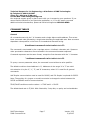
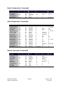
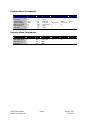
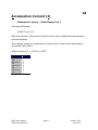
R364 3-Axis Controller/Driver
User Manual – 2 of 2
Commands Guide
Version 2.33
RMS Technologies
2533 N. Carson St. #4698, Carson City, NV 89706-0147
Table of Contents
COMMAND TABLES ................................................................................................. 3
Basic Configuration Commands.......................................................................... 4
Axis Configuration Commands ........................................................................... 4
General Operation Commands............................................................................ 4
Position Move Commands .................................................................................. 5
Velocity Move Commands .................................................................................. 5
R364 PARAMETER USAGE DIAGRAM ....................................................................... 6
Axis Active................................................................................................................... 7
Analog Channel............................................................................................................ 8
Acceleration Current (I) .............................................................................................. 9
Axis Status .................................................................................................................10
Acceleration Threshold ...............................................................................................11
Acceleration maXimum ...............................................................................................12
Baud Selector .............................................................................................................13
Bit Direction ...............................................................................................................14
Current Position .........................................................................................................15
Current Velocity..........................................................................................................16
Digital In ....................................................................................................................17
Digital Out ..................................................................................................................18
Full Duplex .................................................................................................................19
Home Axis ..................................................................................................................20
Hold Current (I) .........................................................................................................21
Interrupt Flags ...........................................................................................................22
Interrupt Mask ...........................................................................................................23
Interpret Velocity .......................................................................................................24
Joystick Active............................................................................................................25
Load Defaults .............................................................................................................26
Linear Go ....................................................................................................................27
Linear Interpret..........................................................................................................28
Lower Limit ................................................................................................................29
Module Address ..........................................................................................................30
Multi-Axis Go ..............................................................................................................31
Multi-Axis Move ..........................................................................................................32
Pulse Divisor ..............................................................................................................33
Phase Current (I) .......................................................................................................34
Position Target ...........................................................................................................35
Reference Configuration .............................................................................................36
Ramp Divisor ..............................................................................................................37
Run Current (I) ..........................................................................................................38
Reference Tolerance ...................................................................................................39
Stop Axis ....................................................................................................................40
Save Data ...................................................................................................................41
Step Resolution ..........................................................................................................42
Soft Stop ....................................................................................................................43
Upper Limit.................................................................................................................44
Velocity miNimum ......................................................................................................45
Velocity Target ...........................................................................................................46
Velocity maXimum ......................................................................................................47
Zero Offset .................................................................................................................48
RMS Technologies
R364 Command List
Page 2
Version 2.33
3/1/2007
Technical Support for Lin Engineering, a distributor of RMS Technologies
By Telephone: 408-919-0200
(Mon.-Fri., 8:00 a.m.-5:00 p.m.)
On the Web: www.linengineering.com
Our technical support group is glad to work with you in answering your questions. If you
cannot find the solution to your particular application, or, if for any reason you need
additional technical assistance, please call technical support at 408-919-0200.
COMMAND TABLES
General
All commands start with the ‘’#’ character and a single alpha module address. Then a twoletter command code followed by a single letter denoting the applicable axis. Next a context
dependent value qualifier in the form of a hexadecimal character string.
#<address><command><axis><value><cr><lf>
The command is terminated by the <carriage return><linefeed> character pair. Spaces or
other punctuation characters are not allowed in the command character sequence.
Command responses use the same format, except the first character with the ‘*’ character
*<address><command><axis><value><cr><lf>
To query a current parameter value, the command is sent without a value qualifier.
The default module or board address is ‘A’, Addresses in the range ‘A’ to ‘Z’ are valid.
Axis selection is by the ‘X’, ‘Y’, ‘Z’, and ‘G’ characters, where ‘G’ is used for all general
commands.
Half-Duplex communication must be used for RS485, and Full-Duplex is optional for RS232
Note: The position of a jumper on module must also be changed to select between the
RS232 and RS485 mode of communications.
TRUE/FALSE conditions use the values 1 = TRUE and 0 = FALSE.
The default baud rate is 57,600. With 8 data bits, 2 stop bits, no parity and no handshake.
RMS Technologies
R364 Command List
Page 3
Version 2.33
3/1/2007
Basic Configuration Commands
Function
Baud Select
Bit Direction
Full Duplex
Load Defaults
Module Addr
Query/New
Q/N
N
Q/N
N
Q/N
Code
BS
BD
FD
LD
MA
Value
Numeric
Binary
Two Digits
None
Alpha
Minimum
3
0
00
A
Maximum
191
11111111
11
Z
Default
7 (Table)
11111111
10
A (0x41)
Value
Boolean
Numeric
Numeric
Numeric
Numeric
Binary
Binary
Numeric
Numeric
Numeric
Numeric
Numeric
Numeric
Numeric
Numeric
Numeric
Numeric
Numeric
Minimum
0
0
0
0
0
0
0
0
0
0
0
0
0
0
0
0
0
-16777215
Maximum
1
7
2047
2047
7
11111111
11111111
16777215
15
255
15
7
15
4095
7
16777215
2047
0
Default
1 (TRUE)
0 = 8/8th
40
1024
1 = 1/8th
0
0
0
4
68
10
7 = 7/8th
0
0
4
16777215
1
0
Value
Chan No
Boolean
Numeric
Numeric
Binary
Binary
Axis
Axis
Axis
None
Minimum
0
0
0
0
0
0
X
0
G
-
Maximum
7
4095
16777215
4095
11111111
11111111
Z
1
Z
-
Default
0
0
0
-
Axis Configuration Commands
Function
Axis Active
Accel Current
Accel Thresh
Accel Max
Hold Current
Interrupt Flags
Interrupt Mask
Lower Limit
Pulse Divisor
Phase Current
Ramp Divisor
Run Current
Ref Configure
Ref Tolerance
Step Resolution
Upper Limit
Velocity Min
Zero Offset
Query/New
Q/N
Q/N
Q/N
Q/N
Q/N
Q
Q/N
Q/N
Q/N
Q/N
Q/N
Q/N
Q/N
Q/N
Q/N
Q/N
Q/N
Q/N
Code
AA
AI
AT
AX
HI
IF
IM
LL
PD
PI
RD
RI
RC
RT
SR
UL
VN
ZO
General Operation Commands
Function
Analog Chan
Axis Status
Current Posn
Current Vel
Digital In
Digital Out
Home Axis
Joystick Active
Stop Axis
Save Data
RMS Technologies
R364 Command List
Query/New
Q
Q
Q/N
Q
Q
N
N
Q/N
N
N
Code
AC
AS
CP
CV
DI
DO
HA
JA
SA
SD
Page 4
Version 2.33
3/1/2007
Position Move Commands
Function
Linear Interpolate
Linear Go
Velocity Max
Position Target
Multi-Axis Move
Multi-Axis Go
Stop Axis
Query/New
N
N
Q/N
Q/N
N
N
N
Code
LI
LG
VX
PT
MM
MG
SA
Value
Two Digits
None
Numeric
Numeric
Two Digits
None
None
Minimum
13
0
-16777215
0
-
Maximum
26
2047
16777215
07
-
Default
1024
0
-
Minimum
0
0
-
Maximum
+/-2047
27
-
Default
0
-
Velocity Move Commands
Function
Velocity Target
Multi-Axis Move
Multi-Axis Go
Stop Axis
RMS Technologies
R364 Command List
Query/New
Q/N
N
N
N
Code
VT
MM
MG
SA
Value
Numeric
Two Digits
None
None
Page 5
Version 2.33
3/1/2007
Figure 1: R364 Parameter Usage Diagram
RMS Technologies
R364 Command List
Page 6
Version 2.33
3/1/2007
AA
Axis Active
Command Only or Query TRUE(1) or FALSE(0).
Only applicable to the X (Motor 1), Y (Motor 2), and Z (Motor 3) axis.
Not to G, the axis alpha used for General commands
When an axis is set inactive then the phase current for the motor is set to
zero. If subsequently the axis is set active, then the phase current for the
motor must be set using the PI command.
Command Example
#AAAX1<cr><lf> Sets X axis active.
Default value is 1
RMS Technologies
R364 Command List
Page 7
Version 2.33
3/1/2007
AC
Analog Channel
Command Only – Axis G Value = Channel No
Returns a 10 bit unsigned value, corresponding to 0 to 5V (See Note), in hex
notation for the input to the selected channel.
Command Example
#AACG3<cr><lf>
Note:
The full-scale reading of 1023 will correspond to the actual value of the
Analog 5VDC supply as measured between pins 1 and 2 of connector J6. If
the supply is exactly 5 VDC then a reading of 1 = 5,000/1024 = 4.88 mV
RMS Technologies
R364 Command List
Page 8
Version 2.33
3/1/2007
AI
Acceleration Current (I)
Command or Query – Value Range 0 to 7
Command Example
#AAIX7<cr><lf>
Sets the fraction of the motor Phase Current (Iph) used during acceleration
and deceleration.
The velocity range for Acceleration Current (Iac) is set by the Acceleration
Threshold (Ath) value
Default value is 0 = (100% or 8/8th)
Fraction
8/8 (100%)
7/8
6/8 (3/4)
5/8
4/8 (1/2)
3/8
2/8 (1/4)
1/8
Value
0
7
6
5
4
3
2
1
RMS Technologies
R364 Command List
Page 9
Version 2.33
3/1/2007
AS
Axis Status
Query Only – No Value
Only applicable to the X (Motor 1), Y (Motor 2), and Z (Motor 3) axis.
Not to G, the axis alpha used for General commands. Two digits are used to
represent Axis Status, and two digits for Switch Status.
Command Example
#AASX<cr><lf>
Response
*AASX15,07<cr>,<lf> Status = 15 Switches = 7
The command returns two values each representing an 8 bit sets of Flags
Status (First digit pair)
MSB (7) Interrupt Flag (Cleared by IF command)
Bit 6
Datagram Waiting
Bit 5
Ref Switch Tripped Z
Bit 4
Z at Target Position
Bit 3
Ref Switch Tripped Y
Bit 2
Y at Target Position
Bit 1
Ref Switch Tripped X
LSB (0)
X at Target Position
Switches
MSB (7)
Bit 6
Bit 5
Bit 4
Bit 3
Bit 2
Bit 1
LSB (0)
(Second digit pair)
Not Used
Not Used
Z Left Limit Switch
Z Right Limit Switch
Y Left Limit Switch
Y Right Limit Switch
X Left Limit Switch
X Right Limit Switch
RMS Technologies
R364 Command List
Page 10
Version 2.33
3/1/2007
AT
Acceleration Threshold
Command or Query – Value Range 0 to 2047
Command Example
#AATX7<cr><lf>
Sets the acceleration value at which the motor current changes from
Acceleration Current (Iac) to Run Current (Icv) during acceleration and from
Run Current (Icv) to Acceleration Current (Iac) during deceleration.
The units are the change in velocity per time unit / 256 with time unit being
set by the Ramp Divisor
Default value is 40
RMS Technologies
R364 Command List
Page 11
Version 2.33
3/1/2007
AX
Acceleration maXimum
Command or Query – Value Range 0 to 2047
Command Example
#AAXX40<cr><lf>
Sets the acceleration limit. The units are the change in velocity per time unit
/ 256 with time unit being set by the Ramp Divisor
Default value is 512
RMS Technologies
R364 Command List
Page 12
Version 2.33
3/1/2007
BS
Baud Selector
Command or Query – Value Range (see table)
Command Example
#ABSG7<cr><lf>
Sets the RS232 and RS485 operating baud rate
The communication parameters are fixed at eight data bits, one stop bit, no
parity, and no handshaking.
The RX buffer size is only 32 bytes, so the host software must control the
message rate to prevent buffer over-run.
RS232 communication uses full duplex, and RS485 uses half-duplex.
For RS485 messaging, transmission direction is switched one character
interval after receipt of the <lf> character and transmission is started in the
other direction one-character interval after the direction change.
The host message start character is ‘#’ (0x23) and the module response
start character is “∗” (0x2B)
Default selector value is 7 (57,600 Baud)
Baud
115,200
76,800
57,600
38,400
28,800
19,200
14,400
9,600
4,800
2,400
Selector
3
5
7
11
15
23
31
47
95
191
RMS Technologies
R364 Command List
Page 13
Version 2.33
3/1/2007
BD
Bit Direction
Command or Query – Binary Value 0 – 11111111
The Logic Level port at J7 is by default an 8 bit output port; however
individual bits can be made inputs by setting the corresponding bits in the
value byte used by this command to zero and read by the response to the
Digital Out (DO) command.
Command Example
#ABDG01111111<cr><lf>
Bit 0 set to input
Default value is 11111111 All outputs
RMS Technologies
R364 Command List
Page 14
Version 2.33
3/1/2007
CP
Current Position
Command or Query – Value Range 0 to 16777215
Normally used to poll the current axis position, but can be used to change
the value of the current location.
Note: If the current position is change while in the Ramp Profile mode, you
will redefine the target location. This is automatically corrected by the
firmware.
Command Example
#ACPX<cr><lf>
RMS Technologies
R364 Command List
Page 15
Version 2.33
3/1/2007
CV
Current Velocity
Query – Value Range 0 – +/-2047
Normally only used to poll the current axis velocity.
Command Example
#ACVX<cr><lf>
RMS Technologies
R364 Command List
Page 16
Version 2.33
3/1/2007
DI
Digital In
Query – Binary Value 0 – 11111111
Used to read the Analog Input port (J6) as logic levels
Command Example
#ADIG<cr><lf>
RMS Technologies
R364 Command List
Page 17
Version 2.33
3/1/2007
DO
Digital Out
Command and Query – Binary Value 0 – 11111111
Used to write the Digital Output port (J7), and if some of the port bits are
set to be inputs with the Bit Direction command, read the inputs mixed with
the outputs as logic levels
Command Example
#ADOG01101111<cr><lf>
Sets bits 0,1, 2, 3, 5, 6 high and bits 4 and 7 low
RMS Technologies
R364 Command List
Page 18
Version 2.33
3/1/2007
FD
Full Duplex
Command only – 0, 1,10, 11 Only valid values
Full Duplex is used only for direct user control via Hyperterm and RS232. For
application software control via RS232, and RS485 Half-Duplex (Not FullDuplex) is normally used
Command Example
#AFDG1<cr><lf>
Full-Duplex On
This command can also be used to turn on Debug in which the actual
messages sent to the Motion Controller are seen.
A second leading digit (0 is Off and 1 is On) is used to control Debug
Command Example
#AFDG11<cr><lf>
Full-Duplex and Debug On
Default is 00 = Debug Off and Full Duplex Off. The set value is remembered
over power cycles.
RMS Technologies
R364 Command List
Page 19
Version 2.33
3/1/2007
HA
Home Axis
Command only – No value
Command Example
#AHAX<cr><lf>
Uses a Velocity Profile move to find the left limit switch. Then makes a
position move away from the limit switch by the amount of the Zero Offset.
At the end of this move the current position is set to be zero.
RMS Technologies
R364 Command List
Page 20
Version 2.33
3/1/2007
HI
Hold Current (I)
Command or Query – Value Range 0 to 7
Command Example
#AHIX7<cr><lf>
Sets the fraction of the motor Phase Current (Iph) used between moves
when velocity is zero.
Default value is 1 = (1/8th)
Fraction
8/8 (100%)
7/8
6/8 (3/4)
5/8
4/8 (1/2)
3/8
2/8 (1/4)
1/8
Value
0
7
6
5
4
3
2
1
RMS Technologies
R364 Command List
Page 21
Version 2.33
3/1/2007
IF
Interrupt Flags
Query – Binary Value 0 – 11111111
Flags are only set if both the associated event has occurred and the
corresponding bit in the Interrupt Mask is set.
Command Example
#AIFG<cr><lf>
MSB (7)
Bit 6
Bit 5
Bit 4
Bit 3
Bit 2
Bit 1
LSB (0)
Stop with Right High
Stop with Left High
Stop with Right Low *
Stop with Left Low *
Stop by Limit Switch
Limit/Reference Switch missed *
Limit/Reference Switch wrong *
Position End of Range reached
Not applicable with standard Limit Switch configuration
RMS Technologies
R364 Command List
Page 22
Version 2.33
3/1/2007
IM
Interrupt Mask
Command or Query – Binary Value 0 – 11111111
Mask bits enable the corresponding flag bits to be set when the associated
event occurs.
Command Example
#AIMX11001001<cr><lf> Bits 0, 3, 6, and 7 set
MSB (7)
Bit 6
Bit 5
Bit 4
Bit 3
Bit 2
Bit 1
LSB (0)
Stop with Right High
Stop with Left High
Stop with Right Low *
Stop with Left Low *
Stop by Limit Switch
Limit/Reference Switch missed *
Limit/Reference Switch wrong *
Position End of Range reached
Not applicable with standard Limit Switch configuration
Default value is 0
RMS Technologies
R364 Command List
Page 23
Version 2.33
3/1/2007
IV
Interpret Velocity
Command or Query – Value Range 0 to 2047 (Default 100)
Sets the path velocity to be used by either Linear or Circular Interpolation.
Command Example
#AIVG400<cr><lf>
Default value is 400
RMS Technologies
R364 Command List
Page 24
Version 2.33
3/1/2007
JA
Joystick Active
Command or Query – TRUE (1) or FALSE (0)
The Analog Input port is used to connect a CH C40009lF-MJ4 3-axis joystick
with four push-buttons.
Command Example:
#AJAG1<cr><lf> sets joystick active
Default value is 0 FALSE
RMS Technologies
R364 Command List
Page 25
Version 2.33
3/1/2007
LD
Load Defaults
Command only – No Value
Used to restore all parameters to their factory default values. To store the
values in EEPROM this command should be followed by a Shut Down
command
Command Example
#ALDG<cr><lf>
See page xx for a list of default values
RMS Technologies
R364 Command List
Page 26
Version 2.33
3/1/2007
LG
Linear Go
Command Only – No Value
Only valid if preceded by a Linear Interpolate (LI) command and the target
position coordinates have been entered.
Command Example
#ALIG07<cr><lf> Linear interpolate a ramp profile for X, Y, Z
#APTX1000<cr><lf> Set target position X to 1000
#APTY1000<cr><lf> Set target position Y to 1000
#APTZ1000<cr><lf> Set target position Z to 1000
#ALGG<cr><lf> Linear Go
RMS Technologies
R364 Command List
Page 27
Version 2.33
3/1/2007
LI
Linear Interpret
Command Only – Value is two digits
Digit 1 (MSD)
0 = Ramp Move
1 = Soft-stop Move
3 = Velocity Move
Digit 2 (LSD)
3 = ZY move
5 = ZX move
6 = XY move
7 = XYZ move
Command Example:
#ALIG07<cr><lf> Linear interpolate a ramp profile for X, Y, Z
#APTX1000<cr><lf> Set target position X to 1000
#APTY1000<cr><lf> Set target position Y to 1000
#APTZ1000<cr><lf> Set target position Z to 1000
#ALGG<cr><lf> Linear Go
RMS Technologies
R364 Command List
Page 28
Version 2.33
3/1/2007
LL
Lower Limit
Command or Query – Value Range 0 to 16777215
Sets the software-controlled range of motion for the axis, to be between the
Lower and Upper Limit values. If the Current Position becomes out of range
when the Limit is set, the motor will move to the new limit value.
Note: If the limit is reached via a velocity move, a HARD STOP will occur.
Command Example
#ALLX200 <cr><lf>
Default value is 0
RMS Technologies
R364 Command List
Page 29
Version 2.33
3/1/2007
MA
Module Address
Command or Query – Value Range ‘A’ to ‘Z’
Assigning modules different addresses allows multiple modules to be run on
a common RS485 Bus. The default address is 65 = ‘A’
Returns and accepts the decimal ASCII value of the character.
Command Example
#AMAG65<cr><lf> Sets the default address A
RMS Technologies
R364 Command List
Page 30
Version 2.33
3/1/2007
MG
Multi-Axis Go
Command only – No value
Only valid if proceeded by a Multi-Axis Move (MM) command. Starts a Ramp
or Velocity move of up to three axis.
Command Example
#AMMG07<cr><lf> Three axis, ramp profile move.
#APTX1000<cr><lf> Set target position X to 1000
#APTY1000<cr><lf> Set target position Y to 1000
#AMGG<cr><lf> Multi-axis Go
RMS Technologies
R364 Command List
Page 31
Version 2.33
3/1/2007
MM
Multi-Axis Move
Command only – Two Digits
Precedes the entry of Target Positions, or Target Velocities for a
simultaneous multiple axis movement.
Command Example
#AMMG07<cr><lf> Three axis, ramp profile move.
#APTX1000<cr><lf> Set target position X to 1000
#APTY1000<cr><lf> Set target position Y to 1000
#AMGG<cr><lf> Multi-axis Go
Only five bits of the value are valid
First Digit (MSD)
Move Profile selector 0 = Ramp, 1 = Soft Stop, 2 = Velocity
Second Digit (LSD)
Represents a 3 bit binary value where
Bit 2
X axis involved
Bit 1
Y axis involved
Bit 0
Z axis involved
Target Position or Velocity commands for the involved axis that are entered
after this command will be held back until a Mult-Axis Go command is
entered.
Command is modal (remains in effect until cancelled)
#AMMG0<x> cancels command
RMS Technologies
R364 Command List
Page 32
Version 2.33
3/1/2007
PD
Pulse Divisor
Command or Query – Value Range 0 – 15
Used to set the update interval of the Pulse Generator.
Command Example
#APDX2<cr><lf>
Default value is 4
RMS Technologies
R364 Command List
Page 33
Version 2.33
3/1/2007
PI
Phase Current (I)
Command or Query – Value Range 0 – 255
Used to match the Driver Phase Current with the motor rated current. Only
valid over the range 0.2 Amp/Phase to 1.5 Amp/Phase. The value 255
corresponds to 1.5 Amp. So for any other current Iph the value is:
255 x Iph/1.5 or Iph x 170
Command Example
#APIX128<cr><lf> Phase Current 0.75 Amps
Note: It is good practice to enter a value not greater than 80% of the motor
rating to maximize motor life.
Default value is 171 (1Amp)
RMS Technologies
R364 Command List
Page 34
Version 2.33
3/1/2007
PT
Position Target
Command or Query – Value Range -1677215 to 16777215
Sets the target position for Ramp Profile moves.
Command Example
#APTX2047<cr><lf>
RMS Technologies
R364 Command List
Page 35
Version 2.33
3/1/2007
RC
Reference Configuration
Command or Query – Value Range 0 to 15 (Default 0)
Allows automatic stopping on limit switch action to be enabled or disabled.
Also allows the stop mode ‘Soft’ or ‘Hard’ to be selected, and either the right
or left switch to be the reference.
Function
Stop Left
Stop Right
Soft Stop
Right/Left
Bit
0
1
2
3
Value
1 = Disable
1 = Disable
1 = Enable
1 = Right
Command Example
#ARCX4<cr><lf> Turns on Soft Stop
Default value is 0
RMS Technologies
R364 Command List
Page 36
Version 2.33
3/1/2007
RD
Ramp Divisor
Command or Query – Value Range 0 – 15
Used to determine the acceleration update interval during ramp action.
Command Example
#ARDX10<cr><lf>
Default value is 10
RMS Technologies
R364 Command List
Page 37
Version 2.33
3/1/2007
RI
Run Current (I)
Command or Query – Value Range 0 to 7
Command Example
#ARIX7<cr><lf>
Sets the fraction of the motor Phase Current (Iph) used during moves when
velocity is constant.
Default value is 7 = (7/8th)
Fraction
8/8 (100%)
7/8
6/8 (3/4)
5/8
4/8 (1/2)
3/8
2/8 (1/4)
1/8
Value
0
7
6
5
4
3
2
1
RMS Technologies
R364 Command List
Page 38
Version 2.33
3/1/2007
RT
Reference Tolerance
Command or Query – Value Range 0 to 4096 (Default 0)
When a limit switch is used as a ‘Reference Switch’ Reference Tolerance can
be used to inhibit interrupts from the switch over a +/- range about the
nominal position.
Command Example
#ARTX4<cr><lf>
Default value is 0
RMS Technologies
R364 Command List
Page 39
Version 2.33
3/1/2007
SA
Stop Axis
Command only – No value
Stops motion on the selected axis, or all axis if the ‘G’ axis value is used. For
velocity profile moves, this is done by setting the target velocity to zero,
resulting in a ramped stop. For ramp moves, the target position is set to be
the same as the current position, resulting in an abrupt stop without a ramp.
Command Example
#ASAG<cr><lf> Stops all axis
RMS Technologies
R364 Command List
Page 40
Version 2.33
3/1/2007
SD
Save Data
Command only – No value
This command results in all current parameter values, including the current
position of each axis, being stored in EEPROM. A flag is set in EEPROM that
will cause the current position values to be restored on power up, providing
that Save Data is the last command received before power down.
Command Example
#ASDG<cr><lf>
RMS Technologies
R364 Command List
Page 41
Version 2.33
3/1/2007
SR
Step Resolution
Command or Query – Value Range 0 to 7
Sets the step resolution and the count units for all position parameters.
Command Example
#ASRX4<cr><lf> Selects 16X Microsteps
Resolution
Full Step
Half Step
4X µStep
8X µStep
16X µStep
32X µStep
64X µStep
64X µStep
Value
0
1
2
3
4
5
6
7
Default value is 4 (16X)
RMS Technologies
R364 Command List
Page 42
Version 2.33
3/1/2007
SS
Soft Stop
Command or Query – TRUE (1) or FALSE (2)
Determines if Softstop is to be used in place of the default ramp move for an
axis.
Command Example:
#ASSX1<cr><lf> Sets Softstop TRUE for x axis
Default value is 0
RMS Technologies
R364 Command List
Page 43
Version 2.33
3/1/2007
UL
Upper Limit
Command or Query – Value Range 0 to 16777215
Sets the software-controlled range of motion for the axis, to be between the
Lower and Upper Limit values. If the Current Position becomes out of range
when the Limit is set, the motor will move to the new limit value.
Note: If the limit is reached via a velocity move, a HARD STOP will occur.
Command Example
#AULX8000000<cr><lf>
Default value is 16777215
RMS Technologies
R364 Command List
Page 44
Version 2.33
3/1/2007
VN
Velocity miNimum
Command or Query – Value Range 0 to 2047
Sets the end-of-ramp down minimum velocity. Must be set to one to ensure
exact target position.
Command Example
#AVNX1<cr><lf>
Default value is 1
RMS Technologies
R364 Command List
Page 45
Version 2.33
3/1/2007
VT
Velocity Target
Command or Query – Value Range 0 to +/-2047
Sets the constant velocity speed for Velocity Profile moves.
Command Example
#AVTX<cr><lf>
RMS Technologies
R364 Command List
Page 46
Version 2.33
3/1/2007
VX
Velocity maXimum
Command or Query – Value Range 0 to 2047
Sets the constant velocity speed for Ramp Profile moves.
Command Example
#AVXX1024<cr><lf>
Default value is 358
RMS Technologies
R364 Command List
Page 47
Version 2.33
3/1/2007
ZO
Zero Offset
Command or Query – Value Range -16777215 to 0
Used by the Home Axis command, this parameter value sets the distance
between the Left Limit Switch and the zero position location.
Command Example
#AZOX-500<cr><lf>
Default value is 0
RMS Technologies
R364 Command List
Page 48
Version 2.33
3/1/2007