1
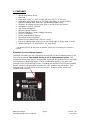
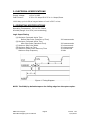
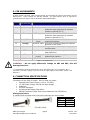
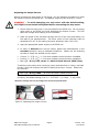
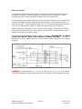
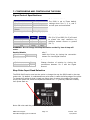
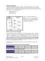
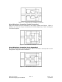
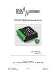
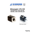
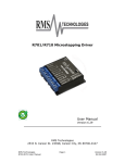
R208 Microstepping Driver
User Manual
Version 1.22
RMS Technologies
2533 N. Carson St. #4698, Carson City, NV 89706-0147
Thank you for purchasing the R208 driver. This product is warranted to be free of
manufacturing defects for one year from the date of purchase.
Technical Support for Lin Enigneering, a distributor for RMS Technologies
By Telephone: 408-919-0200
(Mon.-Fri., 8:00 a.m.-5:00 p.m.)
On the Web: www.linengineering.com
Our technical support group is glad to work with you in answering your questions. If
you cannot find the solution to your particular application, or, if for any reason you
need additional technical assistance, please call technical support at 408-919-0200.
PLEASE READ BEFORE USING
Before you start, ensure that there is a suitable DC power supply and step motor. In
addition, a suitable STEP and DIRECTION pulse source is also required.
DISCLAIMER
The information provided in this document is believed to be reliable. However, no
responsibility is assumed for any possible inaccuracies or omissions. Specifications
are subject to change without notice.
RMS Technologies reserves the right to make changes without further notice to any
products herein to improve reliability, function, or design. RMS Technologies does
not assume any liability arising out of the application or use of any product or circuit
described herein; neither does it convey any license under its patent rights, nor the
rights of others.
CHANGES TO THE R208 DRIVER BOARD
Prior to OCTOBER 1, 2005 the R208 driver board used slower opto-couplers,
limiting the step pulse timing. The old driver board also read step pulses on the
rising edge. A revision change was made on October 1, 2005, using more advanced
opto-couplers. These new opto-couplers can read faster data, yet they are also
more sensitive to older PLC step pulses. If your step pulse signal is not clear, the
R208 will pick this up and the motor will rotate “rough” and irratic. The new boards
read step pulses on the falling edge. If the falling edge of your step pulse is not a
clear signal, the motor will rotate “rough” and irratic.
So far, only a small handful of customers have been affected by the change. Mostly
those that use PLC’s from the early 90’s and older. Customers can still request the
old R208 boards in quantities of 100 per order (blanket releases are OK). The old
boards are under part number: R208-05.
New RoHS style boards: All boards sold after September 31, 2007 are RoHS
compliant. In addition to the RoHS change, the R208 has new features: to be able
to change holding current from 23% or 100% of the run current, and to change
which step pulse edge to read the pulses from: rising edge or falling edge.
Special Symbols
Indicates a WARNING and that this information could prevent
injury, loss of property, or even death (in extreme cases).
RMS Technologies
R208 Microstepping Driver Manual
Page 2
Version 1.22
8/31/2007
R208 User Manual
Product:
Version:
Date:
R208
1.22
8/31/2007
Version History
Version
Date
1.16
02/02/2005
1.17
10/17/2005
1.18
11/09/2006
Updated equation for Voltage
Reference.
Typographical Errors
1.19
2/2/2007
Standardization of User Manuals
1.20
6/7/2007
1.21
8/24/2007
1.22
8/31/2007
Added min. order qty for R20805; updated description of opto
supply.
Updated info on internal resistors
and recommended resistors for
opto-isolatd inputs
Updated RoHS style R208 boards
RMS Technologies
R208 Microstepping Driver Manual
Page 3
Description of Changes
Version 1.22
8/31/2007
TABLE OF CONTENTS
1. FEATURES
5
Automatic Current Cutback Feature
5
2. ELECTRICAL SPECIFICATIONS
6
3. OPERATING SPECIFICATIONS
6
Operating Temperature
Logic Input Timing
6
6
4. MECHANICAL SPECIFICATIONS
7
Dimensions
7
5. PIN ASSIGNMENTS
8
6. CONNECTION SPECIFICATIONS
8
List of Parts
Mating Connectors
8
8
Adjusting the Output Current
9
How to Connect
Alternative Step Resolution Connection
7. CONFIGURING AND CONTROLLING THE R208
10
11
12
Signal Control Specifications
12
Internal Schematic
12
Internal Schematic
Resistor Values for the Opto Supply
13
13
8. MOTOR CONNECTIONS
14
4 Lead Wire Motor Connection
14
6 Lead Wire Motor Connection
14
8 Lead Wire Motor Connection
15
9. TROUBLESHOOTING & FAQ
RMS Technologies
R208 Microstepping Driver Manual
16
Page 4
Version 1.22
8/31/2007
1. FEATURES
•
•
•
•
•
•
•
•
•
•
•
•
•
•
•
•
Bipolar Step Motor Driver
Low Cost
Small size 2.464” x 1.932” x .848” (62.59 x 49.07 x 21.54 mm)
Selectable Step Resolutions of: Full Step, Half Step, 4x, 8x Microsteps
Optically Isolated Step, Direction, and Disable/Enable Inputs
Selection of holding current to be 23% or 100% of the run current
Operates on +12 to +24 VDC
Low Power Dissipation
Efficient Current Control
Thermal Shutdown, Under-voltage Protection
Power-on Indicator
Power Disable/Enable Control
Sinusoidal current waveform
Phase Current Range from 0.35 to 2.0 Amp
Choice of reading each step input on the rising edge or falling edge of pulse
Default Setting is 1.0 Amp RMS or, 1.4 Amp Peak*
* The default current can be preset at different values prior to shipping per customer’s
request
Automatic Current Cutback Feature
The R208 unit offers the user the option of using the Current Cutback function in the
form of a dip switch. The default setting is set to the Enabled position. This
means that when pulse input is discontinued, the driver will produce 23% of the Peak
running current. When this switch is set to the Disabled position, the driver will
produce 100% of the running current. To change the position of the Current Cutback
Switch, simply move the switch towards the “100” mark on the silk screen. This
indicates that it is using 100% of the run current. In other words, there is no
cutback to the current.
RMS Technologies
R208 Microstepping Driver Manual
Page 5
Version 1.22
8/31/2007
2. ELECTRICAL SPECIFICATIONS
Supply Voltage:
Peak Current:
+12 to 24 VDC
0.35 to 2.0 Amps OR 0.25 to 1.4 Amps/Phase
100% duty cycle is OK as long as bottom of unit is 50°C or less
3. OPERATING SPECIFICATIONS
Operating Temperature: -20° to 50° Celsius
Humidity Range: 0 to 95% (non-condensing)
Logic Input Timing
(A) Minimum Command Active Time
Before Step Pulse (Data Set-up Time)
(B) Minimum Command Active Time
After Step Pulse (Data Hold Time)
(C) Minimum Step Pulse Width
(D) Minimum Step Low Time
(E) Maximum Power-Down Recovery Time
Maximum Step Frequency
200 nanoseconds
200 nanoseconds
20 microseconds
20 microseconds
20 milliseconds
30 kHz
Figure 1: Timing Diagram
NOTE: The R208, by default steps on the falling edge into the opto-coupler.
RMS Technologies
R208 Microstepping Driver Manual
Page 6
Version 1.22
8/31/2007
4. MECHANICAL SPECIFICATIONS
Size:
Weight:
Mounting:
Cover:
Plate/Heatsink:
Color:
2.464” x 1.932” x .848” (62.59 mm x 49.07 mm x 21.54 mm)
3.68 oz (104 g)
Four screws, 1.622” x 2.003” (41.20 mm x 50.88 mm)
Steel
Aluminum, Anodized
Black Exterior
Dimensions
Figure 2: R208 Dimensions Diagram
RMS Technologies
R208 Microstepping Driver Manual
Page 7
Version 1.22
8/31/2007
5. PIN ASSIGNMENTS
A DB-9 female connector cable receives power and provides the control connections for the
R208 Driver. Active signals are optically isolated. An open-collector drive is required to
provide pulses for Step, levels for Direction and Disable/Enable.
PIN #
COLOR
FUNCTION
DESCRIPTION
(#26 AWG Lead)
1
2
Red
Black
3
Brown
4
Black/White
5
Orange
6
Green
7
White
8
Blue
9
Yellow
+V
SR1 Input
Motor Supply Voltage. +12 to +24 VDC
Step Resolution 1. Pins 2 & 3 are used to
preset the step resolution by selective
contact to ground (Pin 7)
SR2 Input
Step Resolution 2. Pins 2 & 3 are used to
preset the step resolution by selective
contact to ground (Pin 7)
Enable/Disable This input is used to enable/disable the
Input
output of the driver
Direction Input This input is used to change the rotation
direction of the motor
Power Ground The ground or return of power supply
connects here.
Logic Ground Used to ground to the logic functions (i.e.
step resolution)
Opto Supply +5 VDC input used to supply power to the
(Input)
isolated logic inputs**
Step Clock
Connects to the open-collector drive.
Table 1: Pin Assignments
WARNING! - Do not apply differential voltage on SR1 and SR2, this will
damage the driver.
** The Resistors shall be connected in series with each Input: Pin 4 (Disable), Pin 5
(Direction), and Pin 9 (Step) if you are to use an opto supply of more than +5VDC. See
Section 7.
6. CONNECTION SPECIFICATIONS
List of Parts
Connection of the R208 is simple. Here is what you need:
• External Main Power Supply (+12 to +24 VDC)
• +5 VDC Power Supply used as the Opto Supply
• Voltmeter
• Function Generator
• An appropriate Bipolar Step Motor
• Mating Connector Cables that are provided with the R208 Driver
Mating Connectors
A mating DB-9 connector and crimp style connector will be provided.
Color
Function
Red
A+ Phase
Blue
A- Phase
Green
B+ Phase
Black
B- Phase
Table 2: Pinouts for 090-018
P/N 090-00019
P/N 090-00018
RMS Technologies
R208 Microstepping Driver Manual
Page 8
Version 1.22
8/31/2007
Adjusting the Output Current
Before connecting a step motor to this driver, use the following procedure to check
the output current of the R208 unit. The default output current is set at 1.0 Amp.
WARNING! – To avoid damaging your step motor with the default setting,
the output current should be adjusted before connecting the step motor.
1. Ensure that the step motor is not connected to the R208 unit. Do not supply
pulse input to the R208 unit while adjusting the Output Current. This will
affect the voltage level reading on the voltmeter.
2. Place one probe of the voltmeter through the slot of the cover and attach it to
the lead of the potentiometer. The other probe of the voltmeter shall be
attached to Pin #7 of the mating connector assembly (Part # 90-019).
3. Apply the appropriate power supply to the R208 unit.
4. In order to decrease the current output, adjust the potentiometer in the
clockwise direction using a flathead screwdriver. Please use the following
formula to obtain the desired current output:
•
•
•
Current, I = 2.22 x Vref* + 0.14 when cutback current function is enabled
Current, I = 0.72 x Vref* + 0.14 when cutback current function is disabled
Vref = (I – 0.14)/2.22, where I = Motor’s Rated Current (RMS Value)
To achieve more power when running a motor rated less than 1.4 Amp, use Peak
Current, which will multiply the Motor’s Rated current by 1.4 Amps. Please use
this formula:
Vref = (I – 0.14)/1.554
(I is still the Motor’s Rated Current)
Currently, the default setting is at Vref = 0.55 VDC = (1.0 Amp – 0.14)/1.554
*Reference Voltage refers to the voltage level across the potentiometer.
Figure 3: Adjusting the output current
RMS Technologies
R208 Microstepping Driver Manual
Page 9
Version 1.22
8/31/2007
How to Connect
To connect the R208 according to Figure 4, begin by connecting your step motor to
the R208, for details on how to make that connection refer to Section 8 – Motor
Connections. Next, connect the DB-9 mating connector to the R208.
If using a function generator, take the positive end and connect it to Pin 9 (Step) and
connect the negative end of the generator and connect it to the negative of the +5
VDC power supply. Take the positive end of the +5 VDC power supply and connect it
to Pin 8, the Opto Supply. (Refer to Table 6 for Opto supply resistor values)
Finally, connect the external +12 to +24 VDC power supply. Connect Pin 1 (Power)
to the positive terminal of the power supply. Connect Pin 6 (Power Ground) to the
negative terminal of the power supply.
Remember that the default Current is set to 1.4 Amp. BE SURE NOT TO BURN
YOUR STEP MOTOR WITH THIS DEFAULT CURRENT SETTING. In order to
change this value, please see the section above called “Adjusting the Output
Current”.
Figure 4: Connections Diagram
WARNING! Avoid touching Pin 1 (+12 to 24 VDC) to Pins 2, 3, 4, or 5. These four
pins are connected to optocouplers which can only handle a few milliamps of current.
RMS Technologies
R208 Microstepping Driver Manual
Page 10
Version 1.22
8/31/2007
Alternative Step Resolution Connection
It is possible to change the microstepping resolution by using the signal from the
controller.
Figure 5: Alternative Step Resolution Connection
By sending a high signal to Pin 2 and/or Pin 3, the connection between these pins
will be effectively closed with Pin 7. This will change the microstepping resolution.
Please refer to the Table 3 for Step Resolution Settings.
NOTE: The microstepping resolution should not be changed on the fly, loss of step
may occur.
RMS Technologies
R208 Microstepping Driver Manual
Page 11
Version 1.22
8/31/2007
7. CONFIGURING AND CONTROLLING THE R208
Signal Control Specifications
Default Settings
Current
1.4 Amp
Step Resolution
8x microstep
Direction of rotation
Counterclockwise
Current Cutback
Enabled
Switch
Read step pulse from
Falling Edge (-)
Step Resolution
SR1
SR2
(Black)
(Brown)
Table 3: Default Settings
The R208 is set to these default
settings when Pins 2, 3, 4, and 5
are left open and untouched.
Table 4: Step Resolution Settings
SR1 (Pin 2) and SR2 (Pin 3) are used
to preset the step resolution by
selective contact closure to ground
(Pin 7).
Full
Close
Close
Half
Close
Open
1/4
Open
Close
1/8
Open
Open
WARNING: Do not change the Step Resolution on the fly, loss of step will
occur.
Enable/Disable
Open
Enable
Disable
Close
Table 5
Disable the Driver by closing the connection
between Pin 4 and Signal Ground.
Direction
Clockwise
Counterclockwise
Table 6
Change direction of rotation by closing the
connections between Pin 5 and the Signal
Ground.
Close
Open
Step Pulse Input Read Selection
The R208 RoHS version now has the option to change the way the R208 reads in the step
pulse train. By default, it understands one pulse when it reads the falling edge of the pulse.
To change this setting so that it reads one pulse when it sees a rising edge of the pulse,
simply turn power off, switch the dipswitch towards the “+” (positive) silkscreen marker,
then power back on.
Note: Old units read the pulse on the falling edge (-).
RMS Technologies
R208 Microstepping Driver Manual
Page 12
Version 1.22
8/31/2007
Internal Schematic
The R208 has 3 optically isolated logic inputs. These inputs are isolated to minimize or
eliminate electrical noise coupled onto the drive control signals. Each input is internally
pulled-up to the level of the optocoupler supply and may be connected to sinking outputs on
a controller or a PLC. These inputs are:
Enable/Disable (Pin 4)
Direction (Pin 5)
Step Clock (Pin 9)
Figure 6: Optically Isolated Inputs
Within the Driver lies three 680 Ω
Resistors and three Optocouplers.
The current is limited to 7 mA due to
these three Opto Couplers.
Resistor Values for the Opto Supply
The optocouplers must be powered by an external power supply to maintain
isolation. The Opto Supply for the optocouplers can be between +5 to 24 VDC with
respect to the signal input. It is recommended to use a +5 VDC Opto Supply in
order to limit the current going into the optocouplers to 10 mA. However, if the
supply is greater than +5 VDC then a resistor must be connected in series with each
signal line to maintain 10 mA of current running through the optocouplers. Do NOT
provide more than 10 mA or damage may occur to the driver. Refer to Table 7
& 8 for the corresponding Resistor Values.
The Resistors shall be connected in series with each Input: Pin 4 (Disable), Pin 5 (Direction),
and Pin 9 (Step).
Step & Direction lines have a 470 ohm internal resistor
Voltage:
5V
10V
15V
Ohms needed:
0
500
1000
Wattage rating:
0
¼ watt
¼ watt
Disable line has a 680 ohm internal resistor
Voltage:
5V
10V
15V
Ohms needed:
0
750
1500
Wattage rating:
0
1/8 watt
¼ watt
Table 7 & 8: Resistor Values for inputs
RMS Technologies
R208 Microstepping Driver Manual
Page 13
24V
2000
½ watt
24V
2700
½ watt
Version 1.22
8/31/2007
8. MOTOR CONNECTIONS
Step Motors have 4, 6, or 8 wires. To better understand how to connect your step
motor with your R208 Driver, follow the Figures below for the corresponding motor.
NOTE: The dots indicate the starting position of the wires when wound.
4 Lead Wire Motor Connection
Connect one set of windings to the A terminals. Connect the other set of windings to
the B terminals. If the set of windings is unclear, take a pair of wires; use an
ohmmeter to check for continuity. When you find the first two wires that have
continuity, connect it to the A terminals. Connect the other two to the B terminals.
Figure 7.1: 4 Lead Wire Motor Connection
6 Lead Wire Motor Connection (Half Winding)
Six wire motors can be wound in two ways: Half Winding and Full Winding. Six wire
motors contain a center tap on each of the two windings. For a half-winding
connection, the center tap and one end of the wires are used.
Figure 7.2: 6 Lead Wire Half Winding Connection
6 Lead Wire Motor Connection (Full-Winding)
For a full winding connection, use both end wires, the center tap is ignored. (NC: No
Connection).
RMS Technologies
R208 Microstepping Driver Manual
Page 14
Version 1.22
8/31/2007
Figure 7.3: 6 Lead Wire Full Winding Connection
8 Lead Wire Motor Connection (Parallel Connection)
Eight wire motors can be connected in two ways: Parallel and Series. When in
parallel, the wires are simply connected such that the beginning of each winding are
connected together.
Figure 7.4: 8 Lead Wire Parallel Connection
8 Lead Wire Motor Connection (Series Connection)
Be sure to set the drive current to exactly half of the motor’s rated parallel current
rating when using the series connection.
Figure 7.5: 8 Lead Wire Series Connection
RMS Technologies
R208 Microstepping Driver Manual
Page 15
Version 1.22
8/31/2007
9. TROUBLESHOOTING & FAQ
When you first encounter a problem, the first step is to identify which component is
the cause of the problem. You can do this by swapping out individual components
and verifying if they work independently.
Make sure that you have connected all the wiring correctly, this is a common cause
of most problems
Problems and Solutions
•
The Motor is in Holding Position, but does not rotate:
This means that Power is being supplied to the driver and motor, so the
power supply is OK. However, the signal generator might be causing the
problem. Try changing the signal to TTL. If this does not help, is the external
+5 VDC Power connected? Is Pin 4 (enable/disable) touching Pin 7 (logic
ground)? This will disable the driver from running.
•
When setting the current to the R208, the voltmeter never gives a
clear reading:
If the voltmeter is not giving a clear reading, and you are unable to reach the
desired value for V, then the driver has been damaged.
•
The Microstepping doesn't always change to the correct step
resolution:
Changing the microstepping "on the fly" might ruin the driver. It is
recommended that you disable the motor from running (either turn off the
power, or use the disable pin), then change the step resolution
Will potential back-EMF from the step motor damage the R208?
The circuit on the board is protected and it should not be an issue if you are using
the driver properly.
How long are the DB-9 mating cable and crimp style motor cable? Are the
leads open on the other end?
Both cables are about 12 inches in length. The leads are open at the ends.
How many turns is the output current potentiometer?
The output current potentiometer is multi-turn. We recommend using a voltimeter if
you need to adjust the output current.
Is the R208 a logic sourcing or sinking?
The R208 is a Logic sinking driver. The R208 driver requires an external power
source - power is put into the driver, whereas a logic sourcing driver can provide a
power source.
What is the heat dissipation of the R208?
It has 35°C/Watt heat dissipation, which is very low compared to other drivers.
RMS Technologies
R208 Microstepping Driver Manual
Page 16
Version 1.22
8/31/2007