1
MF1121-03a
CMOS 4-BIT SINGLE CHIP MICROCOMPUTER
S5U1C62000A Manual
(S1C60/62 Family Assembler Package)
NOTICE
No part of this material may be reproduced or duplicated in any form or by any means without the written permission of Seiko
Epson. Seiko Epson reserves the right to make changes to this material without notice. Seiko Epson does not assume any
liability of any kind arising out of any inaccuracies contained in this material or due to its application or use in any product or
circuit and, further, there is no representation that this material is applicable to products requiring high level reliability, such
as medical products. Moreover, no license to any intellectual property rights is granted by implication or otherwise, and there
is no representation or warranty that anything made in accordance with this material will be free from any patent or copyright
infringement of a third party. This material or portions thereof may contain technology or the subject relating to strategic
products under the control of the Foreign Exchange and Foreign Trade Law of Japan and may require an export license from
the Ministry of International Trade and Industry or other approval from another government agency.
Windows 95, Windows 98 and Windows NT are registered trademarks of Microsoft Corporation, U.S.A.
PC/AT and IBM are registered trademarks of International Business Machines Corporation, U.S.A.
All other product names mentioned herein are trademarks and/or registered trademarks of their respective owners.
© SEIKO EPSON CORPORATION 2002, All rights reserved.
Configuration of product number
Devices
S1
C
60N01
F
0A01
00
Packing specifications
00 : Besides tape & reel
0A : TCP BL
2 directions
0B : Tape & reel BACK
0C : TCP BR
2 directions
0D : TCP BT
2 directions
0E : TCP BD
2 directions
0F : Tape & reel FRONT
0G : TCP BT
4 directions
0H : TCP BD
4 directions
0J : TCP SL
2 directions
0K : TCP SR
2 directions
0L : Tape & reel LEFT
0M : TCP ST
2 directions
0N : TCP SD
2 directions
0P : TCP ST
4 directions
0Q : TCP SD
4 directions
0R : Tape & reel RIGHT
99 : Specs not fixed
Specification
Package
D: die form; F: QFP
Model number
Model name
C: microcomputer, digital products
Product classification
S1: semiconductor
Development tools
S5U1
C
60R08
D1
1
00
Packing specifications
00: standard packing
Version
1: Version 1
Tool type
Hx : ICE
Ex : EVA board
Px : Peripheral board
Wx : Flash ROM writer for the microcomputer
Xx : ROM writer peripheral board
Cx
Ax
Dx
Qx
: C compiler package
: Assembler package
: Utility tool by the model
: Soft simulator
Corresponding model number
60R08: for S1C60R08
Tool classification
C: microcomputer use
Product classification
S5U1: development tool for semiconductor products
S1C60/62 Family
INTRODUCTION
Introduction
This document describes the development procedure from assembling source files to debugging. It also
explains how to use each development tool of the S1C62 Family Assembler Package common to all the
models of the S1C62 Family.
How To Read the Manual
This manual was edited particularly for those who are engaged in program development. Therefore, it
assumes that the reader already possesses the following fundamental knowledge:
• Basic knowledge about assembler language
• Basic knowledge about the general concept of program development by an assembler
• Basic operating methods for Windows®95 or Windows NT®4.0
Before installation
See Chapter 1. Chapter 1 describes the composition of this package, and provides a general outline of
each tool.
Installation
Install the tools following the installation procedure described in Chapter 2.
To understand the flow of program development
See the program development flow in Chapter 3.
For coding
See the necessary parts in Chapter 5. Chapter 5 describes the grammar for the assembler language as
well as the assembler functions. Also refer to the following manuals when coding:
S1C62xxx Technical Manual
Covers device specifications, and the operation and control method of the peripheral circuits.
S1C6200/6200A Core CPU Manual
Has the instructions and details the functions and operation of the Core CPU.
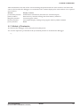
For debugging
Chapter 9 gives detailed explanation of the debugger. Sections 9.1 to 9.8 give an overview of the
functions of the debugger. See Section 9.9 for details of the debug commands. Also refer to the following manuals to understand operations of the In-Circuit Emulator ICE (S5U1C62000H) and the Evaluation Board (S5U1C62xxxE):
S5U1C62000H Manual
Explains the functions and handling methods of the In-Circuit Emulator ICE.
S5U1C62xxxE Manual
Covers the functions and handling methods of the evaluation board designed to evaluate the
hardware specifications of each model.
For details of each tool
Chapters 4 to 9 explain the details of each tool. Refer to it if necessary.
Once familiar with this package
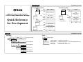
Refer to the listings of instructions and commands contained in Quick Reference.
S5U1C62000A MANUAL
(S1C60/62 FAMILY ASSEMBLER PACKAGE)
EPSON
i
INTRODUCTION
Manual Notations
This manual was prepared by following the notation rules detailed below:
(1) Sample screens
The sample screens provided in the manual are all examples of displays under Windows®95. These
displays may vary according to the system or fonts used.
(2) Names of each part
The names or designations of the windows, menus and menu commands, buttons, dialog boxes, and
keys are annotated in brackets [ ]. Examples: [Command] window, [File | Exit] menu item ([Exit]
command in [File] menu), [Key Break] button, [q] key, etc.
(3) Names of instructions and commands
The CPU instructions and the debugger commands that can be written in either uppercase or lowercase characters are annotated in lowercase characters in this manual, except for user-specified symbols.
(4) Notation of numeric values
Numeric values are described as follows:
Decimal numbers:
Not accompanied by any prefix or suffix (e. g., 123, 1000).
Hexadecimal numbers: Accompanied by the prefix "0x" (e. g., 0x0110, 0xffff).
Binary numbers:
Accompanied by the prefix "0b" (e. g., 0b0001, 0b10).
However, please note that some sample displays may indicate hexadecimal or binary numbers not
accompanied by any symbol. Moreover, a hexadecimal number may be expressed as xxxxh, or a
binary number as xxxxb, for reasons of convenience of explanation.
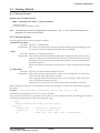
(5) Mouse operations
The operation of pressing the left mouse button once, with the cursor (pointer)
placed in the intended location, is expressed as "to click". The clicking operation of
the right mouse button is expressed as "to right-click".
To double-click: Operations of pressing the left mouse button twice in a row, with the cursor (pointer)
placed in the intended location, are all expressed as "to double-click".
To drag:
The operation of clicking on a file (icon) with the left mouse button and holding it
down while moving the icon to another location on the screen is expressed as "to
drag".
To select:
The operation of selecting a menu command by clicking is expressed as "to select".
To click:
(6) Key operations
The operation of pressing a specific key is expressed as "to enter a key" or "to press a key".
A combination of keys using "+", such as [Ctrl]+[C] keys, denotes the operation of pressing the [C] key
while the [Ctrl] key is held down. Sample entries through the keyboard are not indicated in [ ].
Moreover, the operation of pressing the [Enter] key in sample entries is represented by "↵".
In this manual, all the operations that can be executed with the mouse are described only as mouse
operations. For operating procedures executed through the keyboard, refer to the Windows manual or
help screens.
(7) General forms of commands, startup options, and messages
Items given in [ ] are those to be selected by the user, and they will work without any key entry
involved.
An annotation enclosed in < > indicates that a specific name should be placed here. For example, <file
name> needs to be replaced with an actual file name.
Items enclosed in { } and separated with | indicate that you should choose an item. For example, {A |
B} needs to have either A or B selected.
ii
EPSON
S5U1C62000A MANUAL
(S1C60/62 FAMILY ASSEMBLER PACKAGE)
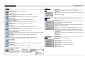
CONTENTS
Contents
CHAPTER
1 GENERAL ................................................................................................ 1
1.1
1.2
Features ......................................................................................................... 1
Tool Composition .......................................................................................... 2
1.2.1 Composition of Package .............................................................................. 2
1.2.2 Outline of Software Tools ............................................................................ 2
CHAPTER
2 INSTALLATION .......................................................................................... 3
2.1
2.2
2.3
CHAPTER
Working Environment .................................................................................... 3
Installation Method ....................................................................................... 4
Directories and Files after Installation ......................................................... 6
3 SOFTWARE DEVELOPMENT PROCEDURE ..................................................... 7
3.1
3.2
Software Development Flow ......................................................................... 7
Development Using Work Bench ................................................................... 8
3.2.1 Starting Up the Work Bench ........................................................................ 8
3.2.2 Creating a New Project ............................................................................... 9
3.2.3 Editing Source Files .................................................................................... 9
3.2.4 Configuration of Tool Options ................................................................... 11
3.2.5 Building an Executable Object .................................................................. 12
3.2.6 Debugging .................................................................................................. 13
CHAPTER
4 WORK BENCH ......................................................................................... 14
4.1
4.2
4.3
Features ........................................................................................................ 14
Starting Up and Terminating the Work Bench .............................................. 14
Work Bench Windows ................................................................................... 15
4.3.1 Window Configuration ............................................................................... 15
4.3.2 Window Manipulation ................................................................................ 16
4.4
Toolbar and Buttons ..................................................................................... 20
4.4.1 Standard Toolbar ........................................................................................ 20
4.4.2 Build Toolbar ............................................................................................. 21
4.4.3 Window Toolbar ......................................................................................... 21
4.4.4 Toolbar Manipulation ................................................................................ 22
4.4.5 [Insert into project] Button on a [Edit] Window ........................................ 22
4.5
Menus ........................................................................................................... 23
4.5.1 [File] Menu ................................................................................................ 23
4.5.2 [Edit] Menu ................................................................................................ 24
4.5.3 [View] Menu ............................................................................................... 24
4.5.4 [Insert] Menu ............................................................................................. 25
4.5.5 [Build] Menu .............................................................................................. 25
4.5.6 [Tools] Menu .............................................................................................. 25
4.5.7 [Window] Menu ......................................................................................... 26
4.5.8 [Help] Menu .............................................................................................. 26
4.6
Project and Work Space ............................................................................... 27
4.6.1 Creating a New Project .............................................................................. 27
4.6.2 Inserting Sources into a Project ................................................................. 28
4.6.3 [Project] Window ....................................................................................... 29
4.6.4 Opening and Closing a Project .................................................................. 29
4.6.5 Files in the Work Space Folder ................................................................... 30
S5U1C62000A MANUAL
(S1C60/62 FAMILY ASSEMBLER PACKAGE)
EPSON
iii
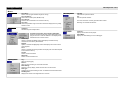
CONTENTS
4.7
Source Editor ............................................................................................... 31
4.7.1 Creating a New Source or Header File ...................................................... 31
4.7.2 Loading and Saving Files .......................................................................... 32
4.7.3 Edit Function ............................................................................................. 33
4.7.4 Tag Jump Function ..................................................................................... 36
4.7.5 Printing ...................................................................................................... 37
4.8
Build Task ..................................................................................................... 37
4.8.1 Preparing a Build Task .............................................................................. 37
4.8.2 Building an Executable Object .................................................................. 37
4.8.3 Debugging .................................................................................................. 38
4.8.4 Executing Other Tools ................................................................................ 39
4.9
Tool Option Settings ..................................................................................... 41
4.9.1 Assembler Options ..................................................................................... 41
4.9.2 Linker Options ........................................................................................... 42
4.9.3 Debugger Options ...................................................................................... 44
4.9.4 HEX Converter Options ............................................................................. 44
4.10 Short-Cut Key List ........................................................................................ 45
4.11 Error Messages ............................................................................................ 45
4.12 Precautions .................................................................................................. 46
CHAPTER
5 ASSEMBLER ............................................................................................ 47
5.1
5.2
Functions ...................................................................................................... 47
Input/Output Files ........................................................................................ 47
5.2.1 Input File .................................................................................................... 47
5.2.2 Output Files ................................................................................................ 48
5.3
5.4
5.5
Starting Method ............................................................................................ 49
Messages ...................................................................................................... 50
Grammar of Assembly Source ...................................................................... 51
5.5.1 Statements .................................................................................................. 51
5.5.2 Instructions (Mnemonics and Pseudo-instructions) .................................. 53
5.5.3 Labels ......................................................................................................... 54
5.5.4 Comments ................................................................................................... 56
5.5.5 Blank Lines ................................................................................................ 56
5.5.6 Register Names .......................................................................................... 56
5.5.7 Numerical Notations .................................................................................. 57
5.5.8 Symbols ...................................................................................................... 58
5.5.9 Operators ................................................................................................... 58
5.5.10 Location Counter Symbol "$" .................................................................. 60
5.6
Section Management .................................................................................... 61
5.6.1 Definition of Sections ................................................................................. 61
5.6.2 Absolute and Relocatable Sections ............................................................ 61
5.6.3 Sample Definition of Sections .................................................................... 62
5.7
Assembler Pseudo-Instructions .................................................................... 63
5.7.1 Include Instruction (#include) .................................................................... 64
5.7.2 Define Instruction (#define) ....................................................................... 65
5.7.3 Macro Instructions (#macro ... #endm) ...................................................... 67
5.7.4 Conditional Assembly Instructions
(#ifdef ... #else ... #endif, #ifndef... #else ... #endif) ................................... 69
5.7.5 Section Defining Pseudo-Instructions (.code, .bss) ................................... 71
5.7.6 Location Defining Pseudo-Instructions (.org, .bank, .page, .align) .......... 72
5.7.7 Symbol Defining Pseudo-Instruction (.set) ................................................ 77
5.7.8 Data Defining Pseudo-Instruction (.codeword) ......................................... 78
5.7.9 Area Securing Pseudo-Instructions (.comm, .lcomm) ................................ 79
iv
EPSON
S5U1C62000A MANUAL
(S1C60/62 FAMILY ASSEMBLER PACKAGE)
CONTENTS
5.7.10 Global Declaration Pseudo-Instruction (.global) .................................... 80
5.7.11 List Control Pseudo-Instructions (.list, .nolist) ........................................ 81
5.7.12 Source Debugging Information Pseudo-Instructions (.stabs, .stabn) ...... 81
5.7.13 Comment Adding Function ...................................................................... 82
5.7.14 Priority of Pseudo-Instructions ................................................................ 82
5.8
5.9
5.10
5.11
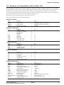
Summary of Compatibility with the Older Tool ........................................... 83
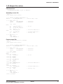
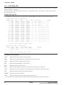
Relocatable List File .................................................................................... 84
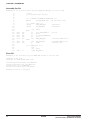
Sample Executions ....................................................................................... 85
Error/Warning Messages .............................................................................. 87
5.11.1 Errors ....................................................................................................... 87
5.11.2 Warning .................................................................................................... 88
5.12 Precautions .................................................................................................. 88
CHAPTER
6 LINKER .................................................................................................. 89
6.1
6.2
Functions ...................................................................................................... 89
Input/Output Files ........................................................................................ 89
6.2.1 Input Files .................................................................................................. 89
6.2.2 Output Files ................................................................................................ 90
6.3
6.4
6.5
6.6
6.7
6.8
6.9
6.10
6.11
6.12
Starting Method ............................................................................................ 91
Messages ...................................................................................................... 94
Linker Command File ................................................................................... 95
Link Map File ............................................................................................... 96
Symbol File ................................................................................................... 97
Absolute List File ......................................................................................... 98
Cross Reference File .................................................................................... 99
Linking ........................................................................................................ 100
Automatic Insertion/Removal/Correction of "pset" Instruction .................. 102
Error/Warning Messages ............................................................................. 103
6.12.1 Errors ...................................................................................................... 103
6.12.2 Warning ................................................................................................... 103
6.13 Precautions ................................................................................................. 104
CHAPTER
7 HEX CONVERTER ................................................................................... 105
7.1
7.2
Functions ..................................................................................................... 105
Input/Output Files ....................................................................................... 105
7.2.1 Input Files ................................................................................................. 105
7.2.2 Output Files ............................................................................................... 105
7.3
7.4
7.5
Starting Method ........................................................................................... 106
Messages ..................................................................................................... 107
Output Hex Files ......................................................................................... 108
7.5.1 Hex File Configuration ............................................................................. 108
7.5.2 Intel-HEX Format ..................................................................................... 108
7.5.3 Motorola-S Format .................................................................................... 109
7.5.4 Conversion Range ..................................................................................... 109
7.6
Error/Warning Messages ............................................................................. 110
7.6.1 Errors ........................................................................................................ 110
7.6.2 Warning ..................................................................................................... 110
7.7
Precautions ................................................................................................. 111
S5U1C62000A MANUAL
(S1C60/62 FAMILY ASSEMBLER PACKAGE)
EPSON
v
CONTENTS
CHAPTER
8 DISASSEMBLER ...................................................................................... 112
8.1
8.2
Functions ..................................................................................................... 112
Input/Output Files ....................................................................................... 112
8.2.1 Input Files ................................................................................................. 112
8.2.2 Output Files ............................................................................................... 112
8.3
8.4
8.5
8.6
Starting Method ........................................................................................... 113
Messages ..................................................................................................... 114
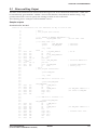
Disassembling Output ................................................................................. 115
Error/Warning Messages ............................................................................. 118
8.6.1 Errors ........................................................................................................ 118
8.6.2 Warning ..................................................................................................... 118
CHAPTER
9 DEBUGGER ............................................................................................ 119
9.1
9.2
Features ....................................................................................................... 119
Input/Output Files ....................................................................................... 119
9.2.1 Input Files ................................................................................................. 119
9.2.2 Output Files ............................................................................................... 120
9.3
Starting Method ........................................................................................... 121
9.3.1 Start-up Format ......................................................................................... 121
9.3.2 Start-up Options ........................................................................................ 121
9.3.3 Start-up Messages ..................................................................................... 122
9.3.4 Hardware Check at Start-up ..................................................................... 122
9.3.5 Method of Termination .............................................................................. 123
9.4
Windows ...................................................................................................... 124
9.4.1 Basic Structure of Window ........................................................................ 124
9.4.2 [Command] Window ................................................................................. 126
9.4.3 [Source] Window ....................................................................................... 127
9.4.4 [Data] Window .......................................................................................... 129
9.4.5 [Register] Window .................................................................................... 129
9.4.6 [Trace] Window ......................................................................................... 130
9.5
Tool Bar ....................................................................................................... 131
9.5.1 Tool Bar Structure ..................................................................................... 131
9.5.2 [Key Break] Button ................................................................................... 131
9.5.3 [Load File] and [Load Option] Buttons ................................................... 131
9.5.4 [Source], [Mix], and [Unassemble] Buttons ............................................ 131
9.5.5 [Go], [Go to Cursor], [Go from Reset], [Step], [Next],
and [Reset] Buttons ................................................................................... 131
9.5.6 [Break] Button .......................................................................................... 132
9.5.7 [Help] Button ............................................................................................ 132
9.6
Menu ............................................................................................................ 133
9.6.1 Menu Structure .......................................................................................... 133
9.6.2 [File] Menu ............................................................................................... 133
9.6.3 [Run] Menu ............................................................................................... 133
9.6.4 [Break] Menu ............................................................................................ 134
9.6.5 [Trace] Menu ............................................................................................ 134
9.6.6 [View] Menu .............................................................................................. 134
9.6.7 [Option] Menu .......................................................................................... 135
9.6.8 [Windows] Menu ....................................................................................... 135
9.6.9 [Help] Menu ............................................................................................. 135
9.7
Method for Executing Commands ............................................................... 136
9.7.1 Entering Commands from Keyboard ......................................................... 136
9.7.2 Executing from Menu or Tool Bar ............................................................. 138
9.7.3 Executing from a Command File .............................................................. 139
9.7.4 Log File ..................................................................................................... 140
vi
EPSON
S5U1C62000A MANUAL
(S1C60/62 FAMILY ASSEMBLER PACKAGE)
CONTENTS
9.8
Debug Functions ......................................................................................... 141
9.8.1 Loading Program and Option Data .......................................................... 141
9.8.2 Source Display and Symbolic Debugging Function ................................. 142
9.8.3 Displaying and Modifying Program, Data, and Register ......................... 144
9.8.4 Executing Program ................................................................................... 146
9.8.5 Break Functions ........................................................................................ 148
9.8.6 Trace Functions ......................................................................................... 150
9.8.7 Coverage ................................................................................................... 153
9.9
Command Reference ................................................................................... 154
9.9.1 Command List ........................................................................................... 154
9.9.2 Reference for Each Command .................................................................. 155
9.9.3 Program Memory Operation ..................................................................... 156
as (assemble mnemonic) .............................................................. 156
pe (program memory enter) ......................................................... 158
pf (program memory fill) ............................................................. 159
pm (program memory move) ........................................................ 160
9.9.4 Data Memory Operation ........................................................................... 161
dd (data memory dump) ............................................................... 161
de (data memory enter) ............................................................... 163
df (data memory fill) .................................................................... 165
dm (data memory move) .............................................................. 166
9.9.5 Register Operation .................................................................................... 167
rd (register display) ..................................................................... 167
rs (register set) ............................................................................. 168
9.9.6 Program Execution ................................................................................... 169
g (go) ........................................................................................... 169
gr (go after reset CPU) ................................................................ 171
s (step) ......................................................................................... 172
n (next) ......................................................................................... 173
9.9.7 CPU Reset ................................................................................................. 174
rst (reset CPU) ............................................................................. 174
9.9.8 Break ......................................................................................................... 175
bp (break point set) ...................................................................... 175
bpc (break point clear) ................................................................ 177
bd (data break) ............................................................................ 178
bdc (data break clear) ................................................................. 180
br (register break) ........................................................................ 181
brc (register break clear) ............................................................. 183
bm (multiple break) ..................................................................... 184
bmc (multiple break clear) .......................................................... 186
bl (break point list) ...................................................................... 187
bac (break all clear) .................................................................... 188
be (break enable) ......................................................................... 189
bsyn (break disable) ..................................................................... 190
9.9.9 Program Display ....................................................................................... 191
u (unassemble) ............................................................................. 191
sc (source code) ........................................................................... 192
m (mix) ......................................................................................... 193
9.9.10 Symbol Information ................................................................................. 194
sy (symbol list) ............................................................................. 194
9.9.11 Load File ................................................................................................. 195
lf (load file) .................................................................................. 195
lo (load option) ............................................................................ 196
9.9.12 ROM Access ............................................................................................ 197
rp (ROM program load) ............................................................... 197
vp (ROM program verify) ............................................................ 198
rom (ROM type) ........................................................................... 199
S5U1C62000A MANUAL
(S1C60/62 FAMILY ASSEMBLER PACKAGE)
EPSON
vii
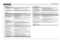
CONTENTS
9.9.13 Trace ........................................................................................................ 200
tc (trace condition) ...................................................................... 200
ta (trace area) .............................................................................. 201
tac (trace area clear) ................................................................... 203
tp (trace pointer) .......................................................................... 204
td (trace data display) ................................................................. 205
ts (trace search) ........................................................................... 207
tf (trace file) ................................................................................. 209
9.9.14 Coverage ................................................................................................. 210
cv (coverage) ............................................................................... 210
cvc (coverage clear) .................................................................... 211
9.9.15 Command File ......................................................................................... 212
com (execute command file) ........................................................ 212
rec (record commands to a file) ................................................... 213
9.9.16 log ........................................................................................................... 214
log (log) ....................................................................................... 214
9.9.17 Map Information ..................................................................................... 215
ma (map information) .................................................................. 215
9.9.18 Mode Setting ........................................................................................... 216
otf (on-the-fly display) ................................................................. 216
tim (time or step mode) ................................................................ 217
9.9.19 Self Diagnosis ......................................................................................... 218
chk (self diagnostic test) .............................................................. 218
9.9.20 Quit ......................................................................................................... 219
q (quit) ......................................................................................... 219
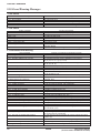
9.10 Error/Warning Messages .............................................................................. 220
QUICK REFERENCE ................................................................................................... 221
viii
EPSON
S5U1C62000A MANUAL
(S1C60/62 FAMILY ASSEMBLER PACKAGE)
CHAPTER 1: GENERAL
CHAPTER 1
GENERAL
1.1 Features
The S1C62 Family Assembler Package contains software development tools that are common to all the
models of the S1C62 Family. The package comes as an efficient working environment for development
tasks, ranging from source program assembly to debugging.
Its principal features are as follows:
Simple composition
A task from assembly to debugging can be made with minimal tools.
Integrated working environment
A Windows-based integrated environment allows the tool chain to be used on its Windows GUI
interface.
Modular programming
The relocatable assembler lets you develop a program which is made up of multiple sources. This
makes it possible to keep a common part independently and to use it as a part or a basis for the next
program.
Source debugging
A debugger can display an assembler source to show its execution status and allow debugging
operations on it. This makes debugging much easier to perform.
Common to all S1C62 chips
The tools (workbench, assembler, linker, hex converter, disassembler, and debugger) are common to
all S1C62 Family models except for several chip dependent masking tools ("Dev" tools). The chip
dependent information is read from the ICE parameter file for each chip.
Complete compatibility with old syntax sources
By supporting old syntax together with the new syntax, an existing ".dat" sources written for old 62
tools are available with these new tools.
S5U1C62000A MANUAL
(S1C60/62 FAMILY ASSEMBLER PACKAGE)
EPSON
1
CHAPTER 1: GENERAL
1.2 Tool Composition
1.2.1 Composition of Package
The S1C62 Family Assembler Package contains the items listed below. When it is unpacked, make sure
that all items are supplied.
1) CD-ROM ................................................................................. One
2) Warranty card ......................................................................... One each in English and Japanese
1.2.2 Outline of Software Tools
The following shows the outlines of the software tools included in the package:
Assembler (as62.exe)
Converts the mnemonic of the source files into object codes (machine language) of the S1C62. The
results are output in a relocatable object file. This assembler includes preprocessing functions such as
macro definition/call, conditional assembly, and file-include functions.
Linker (lk62.exe)
Links the relocatable objects created by the assembler by fixing the memory locations, and creates
executable absolute object codes. The linker also provides an auto PSET insertion/correction function
allowing the programmer to create sources without having to know branch destination page numbers.
Hex converter (hx62.exe)
Converts an absolute object in IEEE-695 format output from the linker into ROM-image data in IntelHEX format or Motorola-S format. This conversion is needed when making the ROM or when creating mask data using the development tools provided with each model.
Disassembler (ds62.exe)
Disassembles an absolute object file in IEEE-695 format or a hex file in Intel-HEX format, and restores
it to a source format file. The restored source file can be processed in the assembler/linker/hex
converter to obtain the same object or hex file.
Debugger (db62.exe)
This software performs debugging by controlling the ICE hardware tool. Commands that are used
frequently, such as break and step, are registered on the tool bar, minimizing the necessary keyboard
operations. Moreover, sources, registers, and command execution results can be displayed in multiple
windows, with resultant increased efficiency in the debugging tasks. The debugger has both Windows
and DOS user interfaces available.
Work Bench (wb62.exe)
This software provides an integrated development environment with Windows GUI. Creating/
editing source files, selecting files and major start-up options, and the start-up of each tool can be
made with simple Windows operations.
2
EPSON
S5U1C62000A MANUAL
(S1C60/62 FAMILY ASSEMBLER PACKAGE)
CHAPTER 2: INSTALLATION
CHAPTER 2
INSTALLATION
This chapter describes the required working environments for the tools supplied in the S1C62
Family Assembler Package and their installation methods.
2.1 Working Environment
To use the S1C62 Family Assembler Package, the following conditions are necessary:
Personal computer
An IBM PC/AT or a compatible machine which is equipped with a CPU equal to or better than a
Pentium 75 MHz, and 32MB or more of memory is recommended.
To use the optional In-Circuit Emulator ICE, the personal computer also requires a serial port (with a
D-sub 9 pin).
Display
A display unit capable of displaying 800 × 600 dots or more is necessary.
Hard disk and CD-ROM drive
Since the installation is done from a CD-ROM to a hard disk, a CD-ROM drive and a hard disk drive
are required.
Mouse
A mouse is necessary to operate the tools.
System software
The S1C62 Family Assembler Package supports Microsoft® Windows®95 (English or Japanese) and
Windows NT®4.0 (English or Japanese).
Other development tools
To debug the target program, the optional In-Circuit Emulator ICE (S5U1C62000H) and an Evaluation
Board (S5U1C62xxxE) are needed as the hardware tools.
The evaluation board is prepared for each S1C62 model.
S5U1C62000A MANUAL
(S1C60/62 FAMILY ASSEMBLER PACKAGE)
EPSON
3
CHAPTER 2: INSTALLATION
2.2 Installation Method
The supplied CD-ROM contains the installer (Setup.exe) that installs the tools.
To install the tools
(1) Start up Windows®95 or Windows NT®4.0.
When Windows has already activated, terminate all
the programs activated.
(2) Insert the CD-ROM into the CD-ROM drive, and
display its contents.
(3) Start up the Setup.exe by double-clicking the icon.
Welcome
(4) Click [Next>] to continue installation.
Choose Destination Location
A dialog box appears for specifying the installation
directory.
(5) Click [Next>] if the default directory
"C:\EPSON\S1C62" is not changed to another
directory.
To install the tools to another directory
Open the [Choose Folder] dialog box by clicking
[Browse...] and then enter the path name or choose
directory. Close the dialog box by clicking [OK] and
then click [Next>].
The installation starts after this selection.
4
EPSON
S5U1C62000A MANUAL
(S1C60/62 FAMILY ASSEMBLER PACKAGE)
CHAPTER 2: INSTALLATION
InstallShield Wizard Complete
(6) Click [Finish] to terminate the installer.
Program Menu
Installer registers the WorkBench62 icon to the program
menu.
To discontinue installation
The dialog boxes that appear during installation have a [Cancel] button. To discontinue installation,
click [Cancel] when a dialog box appears.
To uninstall the tools
Use [Add/Remove Programs] in the control panel to uninstall the tools.
S5U1C62000A MANUAL
(S1C60/62 FAMILY ASSEMBLER PACKAGE)
EPSON
5
CHAPTER 2: INSTALLATION
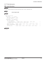
2.3 Directories and Files after Installation
The installer copies the following files in the specified directory (default is "C:\EPSON\S1C62"):
[Specified folder]
README.TXT
... ReadMe document
[bin]
WB62.EXE
AS62.EXE
LK62.EXE
HX62.EXE
DS62.EXE
DB62.EXE
IEEE695.DLL
HEXLIB.DLL
AS62.DLL
CORE62.DLL
ICE62.DLL
MSVCRT.DLL
OLEPRO32.DLL
SPAWNEX.EXE
... Work bench
... Assembler
... Linker
... Hex converter
... Disassembler
... Debugger
... Object format library for debugger
... Hex file library for debugger
... Inline assembler for debugger
... CPU library for debugger
... ICE library for debugger
... Run time library for work bench
... OLE library for work bench
... Child task library for work bench
[English]
MANUAL_E.PDF
DEV_MANUAL_E.PDF
[Japanese]
MANUAL_J.PDF
DEV_MANUAL_J.PDF
... Manual folder (English)
... S5U1C62000A Manual
... S1C60/62 Family Development Tool Manual
... Manual folder (Japanese)
... S5U1C62000A Manual
... S1C60/62 Family Development Tool Manual
[doc]
[dev62]
[bin]
WINFOG.EXE
WINSOG.EXE
WINMDC.EXE
WINMLA.EXE
[62XXX]
:
[dos]
:
... Function option generator
... Segment option generator
... Mask data checker
... Melody assembler
... Model-dependent files for development tools
... Model-dependent files for development tools (DOS version)
Note: Work bench assumes the above directory structure. Do not rename these folders or file names and
do not change the tree structure.
Online manual in PDF format
The online manuals are provided in PDF format, so Adobe Acrobat Reader Ver. 4.0 or later is needed
to read it.
6
EPSON
S5U1C62000A MANUAL
(S1C60/62 FAMILY ASSEMBLER PACKAGE)
CHAPTER 3: SOFTWARE DEVELOPMENT PROCEDURE
CHAPTER 3
SOFTWARE DEVELOPMENT PROCEDURE
This chapter outlines a basic development procedure.
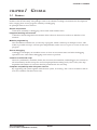
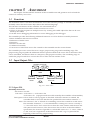
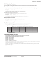
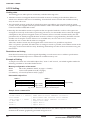
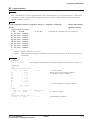
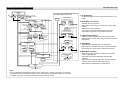
3.1 Software Development Flow
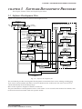
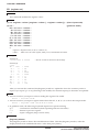
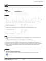
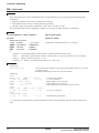
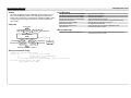
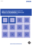
Figure 3.1.1 represents a flow of software development work.
Work Bench
wb62
Make
file
file.MAK
Development tools for each model
file.S
or file.DAT
Assembly
source file(s)
file.par
Function Option
Generator fog62XX
Assembler
fileF.HEX
as62
Assembly
list file(s)
Linker
command file
file.LST
file.O
Object
file(s)
file.CM
Function option
HEX file
file.MS
Preprocessed
source file(s)
file.ABS
Link map file file.MAP
Absolute
object file
file.ALS
Absolute
list file
Cross
file.XRF reference
file
HEX converter
hx62
Motorola-S
format files
Intel-HEX
format files
file.HSA
file.LSA
or fileL.HEX
fileH.HEX
file.SEG
Segment option
source file
Segment Option
Generator sog62XX
Linker
lk62
Symbol file file.SYM
fileF.DOC
Function option
document file
fileS.HEX
Segment option
HEX file
fileS.DOC
Segment option
document file
Melody
data file
file.mel
Melody Assembler
mla62XX
fileA.HEX
Melody
HEX file
fileA.DOC
Melody
document file
Disassembler
ds62
Mask Data Checker
mdc62XX
file.MS
file.PAn
Mask
data file
Disassembled
source file
Debugger
db62
In-Circuit Emulator
Fig. 3.1.1 Software development flow
The work bench provides an integrated development environment from source editing to debugging.
Tools such as the assembler and linker can be invoked from the work bench. The tools can also be invoked individually from the DOS prompt.
Refer to the respective chapter for details of each tool.
The part indicated as "Development tools for each model" is not covered in this manual. For details, refer
to the tool manual associated with each specific model.
S5U1C62000A MANUAL
(S1C60/62 FAMILY ASSEMBLER PACKAGE)
EPSON
7
CHAPTER 3: SOFTWARE DEVELOPMENT PROCEDURE
3.2 Development Using Work Bench
This section shows a basic development procedure using the work bench wb62.
Refer to Chapter 4, "Work Bench", for operation details.
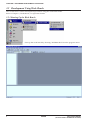
3.2.1 Starting Up the Work Bench
Start up the work bench by choosing "WorkBench62" from the program menu.
8
EPSON
S5U1C62000A MANUAL
(S1C60/62 FAMILY ASSEMBLER PACKAGE)
CHAPTER 3: SOFTWARE DEVELOPMENT PROCEDURE
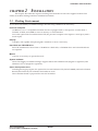
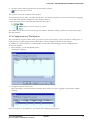
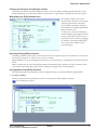
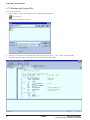
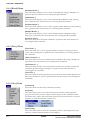
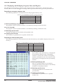
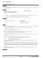
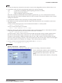
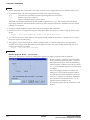
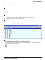
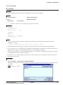
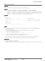
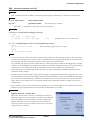
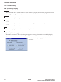
3.2.2 Creating a New Project
The work bench manages necessary file and tool setting information as a project.
First a new project file should be created.
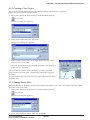
1. Select [New] from the [File] menu (or click the [New] button).
[New] button
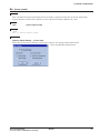
The [New] dialog box appears.
2. Select [E0C Project File] and click [OK].
The [Project] dialog box appears.
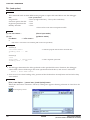
3. Enter a project name, select an ICE parameter file and select a
directory, then click [OK].
∗ The [ICE parameter file:] box lists the parameter files that exist
in the "dev62" directory.
The work bench creates a folder (directory) with the specified
project name as a work space, and puts the project file (.epj) into
the folder.
The specified project name will also be used for the absolute object
and other files.
Created project
[Project] window
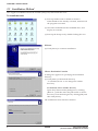
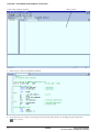
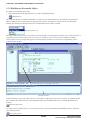
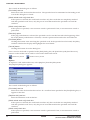
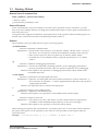
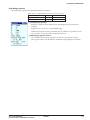
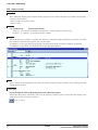
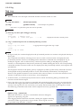
3.2.3 Editing Source Files
The work bench has an editor function. This makes it possible to edit source files without another editor.
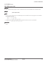
To create a new source file:
1. Select [New] from the [File] menu (or click the [New] button).
[New] button
The [New] dialog box appears.
2. Select [E0C Assembly Source File] and click [OK].
S5U1C62000A MANUAL
(S1C60/62 FAMILY ASSEMBLER PACKAGE)
EPSON
9
CHAPTER 3: SOFTWARE DEVELOPMENT PROCEDURE
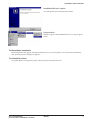
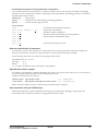
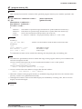
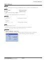
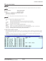
A new edit window appears.
[Edit] window
3. Enter source codes in the [Edit] window.
4. Save the source in a file by selecting [Save] from the [File] menu (or clicking the [Save] button).
[Save] button
10
EPSON
S5U1C62000A MANUAL
(S1C60/62 FAMILY ASSEMBLER PACKAGE)
CHAPTER 3: SOFTWARE DEVELOPMENT PROCEDURE
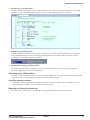
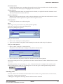
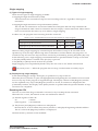
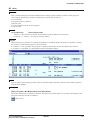
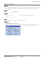
5. Click the [Insert into project] button on the [Edit] window.
[Insert into project] button
The created source file is added in the project.
To add existing source files, use [Files into project...] in the [Insert] menu. It can also be done by dragging
source files from Windows Explorer to the project window.
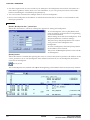
Create necessary source files and add them into the project.
Sample list in the [Project] window
The added source files are listed in the project window. Double-clicking a listed source file name opens
the edit window.
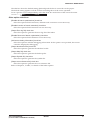
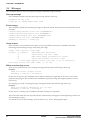
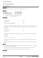
3.2.4 Configuration of Tool Options
The work bench supports all the start up options of each tool and they can be selected in a dialog box. A
make process for generating an executable object will be configured based on the settings.
In addition to option selection, command files for the linker and debugger can be configured here.
To set tool options:
1. Select [Setting...] from the [Build] menu.
A dialog box appears.
2. Configure options if necessary.
Check box items can be selected by clicking. Items in the list can be toggled or entered by doubleclicking.
Refer to Chapter 4, "Work Bench", for details of the [Settings] dialog box.
S5U1C62000A MANUAL
(S1C60/62 FAMILY ASSEMBLER PACKAGE)
EPSON
11
CHAPTER 3: SOFTWARE DEVELOPMENT PROCEDURE
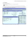
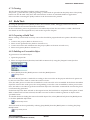
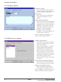
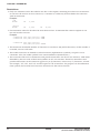
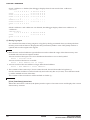
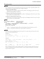
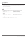
3.2.5 Building an Executable Object
To make an executable object file:
1. Select [Build] from the [Build] menu (or click the [Build] button).
[Build] button
This will invoke the assembler and linker to create an executable object file. If a HEX file format (Intel
HEX or Motorola S) is selected by the [Output format] box, the HEX converter will be invoked after
linking. By default, an absolute object file in IEEE-695 format will be created.
[Output format] box
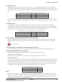
Messages delivered from each executed tool are displayed in the [Output] window. The work bench has a
tag-jump function that jumps to the source line in which an error has occurred by double-clicking a
source syntax error message that appears in the [Output] window. It opens the corresponding source
window if it is closed.
Linked with the corresponding source line
[Output] window
In the build task, a general make process is executed to update the least necessary files. To rebuild all the
files without the make function, select [Rebuild All] from the [Build] menu (or click the [Rebuild All]
button).
[Rebuild All] button
To invoke the assembler only to correct syntax errors, select [Assemble] in the [Built] menu (or click the
[Assemble] button).
[Assemble] button
12
EPSON
S5U1C62000A MANUAL
(S1C60/62 FAMILY ASSEMBLER PACKAGE)
CHAPTER 3: SOFTWARE DEVELOPMENT PROCEDURE
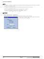
3.2.6 Debugging
To debug the executable object:
1. Select [Debug] from the [Build] menu (or click the [Debug] button).
[Debug] button
The debugger starts up with the specified ICE parameter file and then loads the executable object file.
Note: Make sure that the ICE is ready to debug before invoking the debugger. Refer to the ICE hardware
manual for settings and startup method of the ICE.
For the debugging functions and operations, refer to Chapter 9, "Debugger".
S5U1C62000A MANUAL
(S1C60/62 FAMILY ASSEMBLER PACKAGE)
EPSON
13
CHAPTER 4: WORK BENCH
CHAPTER 4
WORK BENCH
This chapter describes the functions and operating method of the Work Bench wb62.
4.1 Features
The Work Bench wb62 provides an integrated operating environment ranging from editing source files to
debugging. Its functions and features are summarized below:
• Source edit function that supports copy/paste, find/replace, print, label jump and tag jump from error
messages.
• Allows simple management of all necessary files and information as a project.
• General make process to invoke necessary tools and to update the least necessary files.
• Supports all options of the assembler, linker, HEX converter, disassembler and debugger.
• Windows GUI interface for simple operation.
4.2 Starting Up and Terminating the Work Bench
To start up the work bench
Choose "WorkBench62" from the [Program] menu to
start up the work bench.
∗ If "WorkBench62" is not registered in the [Program]
menu, it means that the installation was not successful. Therefore, reinstall the tools by referring to
Chapter 2, "Installation".
When the work bench starts up, the window shown
below appears.
To terminate the work bench
Select [Exit] from the [File] menu.
14
EPSON
S5U1C62000A MANUAL
(S1C60/62 FAMILY ASSEMBLER PACKAGE)
CHAPTER 4: WORK BENCH
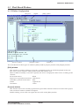
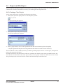
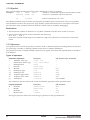
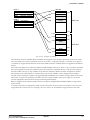
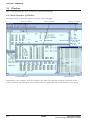
4.3 Work Bench Windows
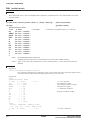
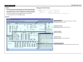
4.3.1 Window Configuration
Menu bar
[Project] window
Toolbar
[Edit] window
[Output] window
Status bar
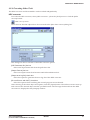
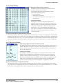
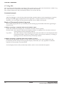
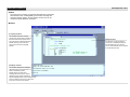
The work bench has three types of windows: [Edit] window, [Project] window and [Output] window.
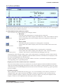
[Edit] window
This window is used for editing a source file. A standard text file can also be displayed in this window. Two or more windows can be opened in the edit window area.
When an E0C62 assembly source file is opened, the source is displayed with in colors according to the
contents.
S1C62 instructions:
Black
Preprocess (#) pseudo-instructions: Dark brown
Assemble (.) pseudo-instructions: Blue
Labels:
Light brown
Comments:
Green
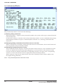
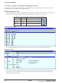
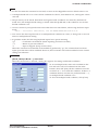
[Project] window
This window shows the currently opened work space folder and lists all the source files in the project,
with a structure similar to Windows Explorer.
Double-clicking a source file icon opens the source file in the [Edit] window.
S5U1C62000A MANUAL
(S1C60/62 FAMILY ASSEMBLER PACKAGE)
EPSON
15
CHAPTER 4: WORK BENCH
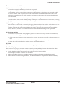
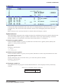
[Output] window
This window displays the messages delivered from the executed tools in a build or assemble process.
Double-clicking a syntax error message with a source line number displayed in this window activates
or opens the [Edit] window of the corresponding source so that the source line in which the error has
occurred can be viewed.
Menu bar
Refer to Section 4.5.
Toolbar
Refer to Section 4.4.
Status bar
Shows help messages when the mouse cursor is placed on a menu item or a button.
It also indicates the cursor position in the [Edit] window, Key lock status (Num lock, Caps lock, Scroll
lock).
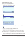
4.3.2 Window Manipulation
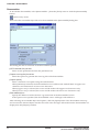
Resizing the windows
←| |→
←| |→
Each window area can be
resized by dragging the window boundary. The size
information is saved when the
work bench is terminated. So
the same window layout will
appearat the next time the work
bench starts up.
Double click
Floating and docking the
[Project] and [Output]
window
The [Project] window and the
[Output] window can be made
a floating window by doubleclicking the window boundary
and the floating window can be
moved and resized in the work
bench window. The floating
window will be restored to a
docking window by double
clicking the window's title bar
or dragging the title bar
towards an edge of the work
bench window.
16
EPSON
S5U1C62000A MANUAL
(S1C60/62 FAMILY ASSEMBLER PACKAGE)
CHAPTER 4: WORK BENCH
Closing the [Project] and [Output] window
The [Project] window and the [Output] window can be closed by selecting [Project Window] and
[Output Window] from the [View] menu, respectively. To open them, select the menu items again.
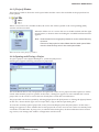
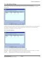
Maximizing the [Edit] window area
The [Edit] window area can be
maximized to the full screen size by
selecting [Full Screen] from the
[View] menu. All other windows
and toolbars are hidden behind the
[Edit] window area.
To return it to the normal display,
click the button that appears on the
screen. This button can be moved
anywhere in the screen by dragging
its title bar. Pressing the [ESC] key
also returns the window to the
normal display.
Opening/Closing [Edit] windows
An [Edit] window opens when a source file (text file) is loaded using a menu, button or a file icon in
the [Project] window, or when a new source is created.
[Edit] windows close by clicking the [Close] box of each window or selecting [Close] from the [File]
menu.
When a project file is saved, the [Edit] window information (files opened, size and location) is also
saved. So the next time the project opens, editing can begin in the saved condition.
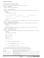
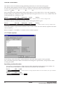
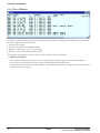
Arrangement of the [Edit] windows
The [Edit] windows being opened can be arranged similar to standard Windows applications.
1 Cascade windows
Select [Cascade] from the [Window] menu or click the [Cascade Windows] button.
[Cascade Windows] button
S5U1C62000A MANUAL
(S1C60/62 FAMILY ASSEMBLER PACKAGE)
EPSON
17
CHAPTER 4: WORK BENCH
2 Tile windows
To tile windows vertically, select [Tile Vertically] from the [Window] menu or click the [Tile Vertically]
button.
[Tile Vertically] button
To tile windows horizontally, select [Tile Horizontally] from the [Window] menu or click the [Tile
Horizontally] button.
[Tile Horizontally] button
18
EPSON
S5U1C62000A MANUAL
(S1C60/62 FAMILY ASSEMBLER PACKAGE)
CHAPTER 4: WORK BENCH
3 Maximizing an [Edit] window
Click the [Maximize] button on the window title bar. The window will be maximized to the [Edit]
window area size and other [Edit] windows will be hidden behind the active window.
4 Minimizing an [Edit] window
Click the [Minimize] button on the window title bar. The window will be minimized as a window
icon. The minimized icons can be arranged at the bottom of the [Edit] window area by selecting
[Arrange Icons] from the [Window] menu.
5 Moving and resizing an [Edit] window
The [Edit] window allows changing of its location and its size in the same way as the standard
Windows applications if it is not maximized.
Switching active [Edit] window
Click the window to be activated if it can be viewed. Otherwise, select the window name (source file
name) from the currently-opened window list in the [Window] menu.
Scrolling display contents
A standard scroll bar appears if the display contents exceed the display size of a window. Use it to
scroll the display contents. The arrow keys can also be used.
Showing and hiding the status bar
The status bar can be shown or hidden by selecting [Status Bar] from the [View] menu.
S5U1C62000A MANUAL
(S1C60/62 FAMILY ASSEMBLER PACKAGE)
EPSON
19
CHAPTER 4: WORK BENCH
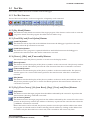
4.4 Toolbar and Buttons
Tree types of toolbars have been implemented in the work bench: standard toolbar, build toolbar and
window tool bar.
Standard toolbar
Build toolbar
Window toolbar
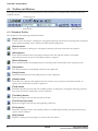
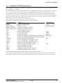
4.4.1 Standard Toolbar
This toolbar has the following standard buttons:
[New] button
Creates a new document. A dialog box will appear allowing selection from among three document
types: E0C62 assembly source, E0C62 assembly header and project.
[Open] button
Opens a document. A dialog box will appear allowing selection of the file to be opened.
[Save] button
Saves the document in the active [Edit] window to the file. The file will be overwritten.
This button becomes inactive if no [Edit] window is opened.
[Save All] button
Saves the documents of all [Edit] windows and the project information to the respective files.
[Cut] button
Cuts the selected text in the [Edit] window to the clipboard.
[Copy] button
Copies the selected text in the [Edit] window to the clipboard.
[Paste] button
Pastes the text copied on the clipboard to the current cursor position in the [Edit] window or
replaces the selected text with the copied text.
[Find] button
Finds the specified word in the active [Edit] window. A dialog box will appear allowing specification of the word to be found and a search condition.
[Find Next] button
Finds next target word towards the end of the file.
[Find Previous] button
Finds next target word towards the beginning of the file.
[Print] button
Prints the document in the active [Edit] window. A standard print dialog will appear allowing a
specific print condition.
[Help] button
Displays a dialog box showing the version of the work bench.
20
EPSON
S5U1C62000A MANUAL
(S1C60/62 FAMILY ASSEMBLER PACKAGE)
CHAPTER 4: WORK BENCH
4.4.2 Build Toolbar
This tool bar has the following buttons and list boxes used to build a project:
[Assemble] button
Assembles the assembly source in the active [Edit] window. This button becomes active only when
the active [Edit] window shows an assembly source file.
[Build] button
Builds the currently opened project using a general make process.
[Rebuild All] button
Builds the currently opened project. All the source files will be assembled regardless of whether
they are updated or not.
[Stop Build] button
Stops the build process being executed. This button becomes active only while a build process is
being executed.
[ICE Parameter] pull-down list box
Selects the ICE parameter file for the model being developed. In this box, all the
ICE parameter files that exist in the "dev62" directory are listed.
[Output Format] pull-down list box
Selects an executable object file format. Three types of formats are available:
IEEE-695 absolute object format, Intel HEX format and Motorola S format. The
build process will generate an executable object in the format selected here.
[HEX Convert] button
Invokes the HEX converter to convert an absolute object into an Intel HEX object or a Motorola S
object. A dialog box will appear allowing selection of an absolute object and options of the HEX
converter.
[Disassemble] button
Invokes the disassembler to disassemble an absolute object. A dialog box will appear allowing
selection of an absolute object and options of the disassembler.
[Debug] button
Invokes the debugger with the specified ICE parameter file.
4.4.3 Window Toolbar
This tool bar has the following buttons used in window manipulation:
[Cascade] button
Cascades the opened [Edit] windows.
[Tile Horizontally] button
Tiles the opened [Edit] window horizontally.
[Tile Vertically] button
Tiles the opened [Edit] window vertically.
S5U1C62000A MANUAL
(S1C60/62 FAMILY ASSEMBLER PACKAGE)
EPSON
21
CHAPTER 4: WORK BENCH
4.4.4 Toolbar Manipulation
Hiding and showing toolbars
Each toolbar can be hidden if not needed. Select the toolbar name from the [View] menu. This operation toggles between hiding and showing the toolbar.
Changing the toolbar location
Toolbars can be moved to another location in the toolbar area by dragging them. If a toolbar is moved
out of the toolbar area, it will be changed to a window.
4.4.5 [Insert into project] Button on a [Edit] Window
[Insert into project] button
When a source file (.s, .ms or .dat) is opened, the [Insert into project] button appears on the [Edit] window. It can be used to insert the source file into the current opened project.
For other file types, the [Edit] window opens without the [Insert into project] button.
22
EPSON
S5U1C62000A MANUAL
(S1C60/62 FAMILY ASSEMBLER PACKAGE)
CHAPTER 4: WORK BENCH
4.5 Menus
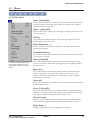
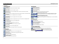
4.5.1 [File] Menu
[New...] ([Ctrl]+[N])
Creates a new document. A dialog box will appear allowing selection
from among three document types: E0C62 assembly source, E0C62
assembly header and project.
[Open...] ([Ctrl]+[O])
Opens a document. A dialog box will appear allowing selection of the
file to be opened.
[Close]
Closes the active [Edit] window. This menu item appears when an
[Edit] window becomes active.
[Open Workspace...]
Opens a project. A dialog box will appear allowing selection of the
project to be opened.
[Close Workspace]
Closes the currently opened project. This menu item becomes inactive
if no project is opened.
[Save] ([Ctrl]+[S])
The file names listed in this menu
are recently used source and
project files. Selecting one opens
the file.
Saves the document in the active [Edit] window to the file. The file
will be overwritten. This menu item appears when an [Edit] window
becomes active.
[Save As...]
Saves the document in the active [Edit] window with another file
name. A dialog box will appear allowing specification of a save
location and a file name. This menu item appears when an [Edit]
window becomes active.
[Save All]
Saves the documents of all [Edit] windows and the project information
to the respective files.
[Print...] ([Ctrl]+[P])
Prints the document in the active [Edit] window. A standard [print]
dialog box will appear allowing a specific print condition. This menu
item appears when an [Edit] window becomes active.
[Print Preview]
Displays a print image of the document in the active [Edit] window.
This menu item appears when an [Edit] window becomes active.
[Page Setup...]
Displays a dialog box for selecting paper and printer.
S5U1C62000A MANUAL
(S1C60/62 FAMILY ASSEMBLER PACKAGE)
EPSON
23
CHAPTER 4: WORK BENCH
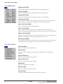
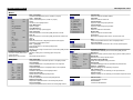
4.5.2 [Edit] Menu
[Undo] ([Ctrl]+[Z])
Undoes the previous executed operation in the [Edit] window.
[Cut] ([Ctrl]+[X])
Cuts the selected text in the [Edit] window to the clipboard.
[Copy] ([Ctrl]+[C])
Copies the selected text in the [Edit] window to the clipboard.
[Paste] ([Ctrl]+[V])
Pastes the text copied on the clipboard to the current cursor position in the
[Edit] window or replaces the selected text with the copied text.
[Select All] ([Ctrl]+[A])
Selects all text in the active [Edit] window.
[Find...] ([Ctrl]+[F])
Finds the specified word in the active [Edit] window. A dialog box will
appear allowing specification of the word to be found and a search condition.
[Replace] ([Ctrl]+[H])
Replaces the specified words in the active [Edit] window with one another. A
dialog box will appear allowing specification of the words.
[Go To] ([Ctrl]+[G])
Jumps to the specified line or label in the active [Edit] window. A dialog box
will appear allowing specification of a line number or a label name.
4.5.3 [View] Menu
[Standard Bar]
Shows or hides the standard toolbar.
[Status Bar]
Shows or hides the status bar located at the bottom of the work bench
window.
[Output Window]
Opens or closes the [Output] window.
[Project Window]
Opens or closes the [Project] window.
[Build Bar]
Shows or hides the build toolbar.
[Window Bar]
Shows or hides the window toolbar.
[Full Screen]
Maximizes the [Edit] window area to the full screen size.
24
EPSON
S5U1C62000A MANUAL
(S1C60/62 FAMILY ASSEMBLER PACKAGE)
CHAPTER 4: WORK BENCH
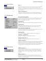
4.5.4 [Insert] Menu
[File...]
Inserts the specified file to the current cursor position in the [Edit]
window or replaces the selected text with the contents of the
specified file. A dialog box will appear allowing selection of the file
to be inserted.
[Files into project...]
Adds the specified source file in the currently opened project. A
dialog box will appear allowing selection of the file to be added.
4.5.5 [Build] Menu
[Assemble] ([Ctrl]+[F7])
Assembles the assembly source in the active [Edit] window. This
menu item becomes active only when the active [Edit] window
shows an assembly source file.
[Build] ([F7])
Builds the currently opened project using a general make process.
[Rebuild All]
Builds the currently opened project. All the source files will be
assembled regardless of whether they are updated or not.
[Stop Build] ([Ctrl]+[Break])
Stops the build process being executed. This button become active
only while a build process is being executed.
[Debug] ([F5])
Invokes the debugger with the specified ICE parameter file.
[Settings...] ([Alt]+[F7])
Displays a dialog box for selecting tool options.
[ICE parameter file...]
Displays a dialog box for selecting an ICE parameter file.
[Output Format...]
Displays a dialog box for selecting an executable object file format.
Three types of formats are available: IEEE-695 absolute object
format, Intel HEX format and Motorola S format. The build process
will generate an executable object in the format selected here.
4.5.6 [Tools] Menu
[HEX Converter...]
Invokes the HEX converter to convert an absolute object into an
Intel HEX object or Motorola S object. A dialog box will appear
allowing selection of an absolute object and options for the HEX
converter.
[Disassembler...]
Invokes the disassembler to disassemble an absolute object. A
dialog box will appear allowing selection of an absolute object and
options for the disassembler.
S5U1C62000A MANUAL
(S1C60/62 FAMILY ASSEMBLER PACKAGE)
EPSON
25
CHAPTER 4: WORK BENCH
4.5.7 [Window] Menu
This menu appears when an [Edit] window is opened.
[Cascade]
Cascades the opened [Edit] windows.
[Tile Horizontally]
Tiles the opened [Edit] window horizontally.
[Tile Vertically]
Tiles the opened [Edit] window vertically.
The currently opened
document file names are
listed in this menu.
Selecting one activates
the [Edit] window.
[Arrange Icons]
Arranges the minimized [Edit] window icons at the bottom of the [Edit] window area.
[Close All]
Closes all the [Edit] windows opened.
4.5.8 [Help] Menu
[About WB62...]
Displays a dialog box showing the version of the work bench.
26
EPSON
S5U1C62000A MANUAL
(S1C60/62 FAMILY ASSEMBLER PACKAGE)
CHAPTER 4: WORK BENCH
4.6 Project and Work Space
The work bench manages a program development task using a work space folder and a project file that
contains file and other information necessary for invoking the development tools.
4.6.1 Creating a New Project
A new project file can be created by the following procedure:
1. Select [New] from the [File] menu or click the [New] button.
[New] button
The [New] dialog box appears.
2. Select [E0C Project File] and click [OK].
The [Project] dialog box appears.
3. Enter a project name, select an ICE parameter file and select a directory, then click [OK].
∗ The [ICE parameter file:] box lists the parameter files that exist in the "dev62" directory.
The work bench creates a folder (directory) with the specified project name as a work space, and puts the
project file (.epj) into the folder.
If a folder which has the same name as that of a specified one already exists in the specified location, the
work bench uses the folder as the work space. Thus you can specify a folder in which sources are created.
The specified project name will also be used for the absolute object and other files.
S5U1C62000A MANUAL
(S1C60/62 FAMILY ASSEMBLER PACKAGE)
EPSON
27
CHAPTER 4: WORK BENCH
4.6.2 Inserting Sources into a Project
The sources created must be inserted into the project.
To insert a source into a project, use one of the four methods shown below:
1. [Insert | Files into project...] menu item
A dialog box appears when this menu item is selected.
Choose a source file from the list box and then click [Open].
2. [File | Open...] menu item or [Open] button
[Open] button
A dialog box appears when this menu item or button is selected.
Choose a source file from the list box and select the [Into project] button, then click [Open].
3. [Insert into project] button on the [Edit] window
[Insert into project] button
When the source file has been opened, click the [Insert into project] button on the [Edit] window. Do
not forget to save the source to the file before inserting into the project.
4. Dragging source files on the [Project] window
Drag source files from Windows Explorer to the [Project] window. These files will be added to the
current project.
When a source file is inserted into the project, the source file name appears in the [Project] window.
Removing a source from the project
To remove a source file from the project, select the source in the [Project] window and then press the
[Delete] key. This removes only the source information, and does not delete the actual source file.
28
EPSON
S5U1C62000A MANUAL
(S1C60/62 FAMILY ASSEMBLER PACKAGE)
CHAPTER 4: WORK BENCH
4.6.3 [Project] Window
The [Project] window shows the work space folder and the source files included in the project that has
been opened.
When a source file icon is double-clicked, the source file will be opened or the corresponding [Edit]
window will be activated.
When the folder icon or a source file icon is double-clicked with the right
mouse button, a shortcut menu including the available build menu items
appears.
Note: Note that the list in the [project] window is not the actual directory
structure.
Sources of the project in other folders than the work space folder
are also listed as they exist in the work space folder.
Shortcut menu in the [Project] window
4.6.4 Opening and Closing a Project
To open a project, select [Open WorkSpace...] from the [File] menu.
A dialog box appears allowing selection of a project file.
The work bench allows only one project to be opened at a time. So if a project has been opened, it will be
closed when another project is opened. At this time, a dialog box appears to select whether the current
project file is to be saved or not if it has not already been saved after a modification.
The project file can also be opened by selecting [Open] from the [File] menu or clicking the [Open] button.
In this case, choose the file type as S1C Project Files (*.epj) in the file open dialog box.
To close the currently opened project file, select [Close WorkSpace] from the [File] menu. At this time, a
dialog box appears to select whether the current project file is to be saved or not if it has not already been
saved after a modification. If [Yes] (save) is selected in this dialog box, all the modification items including sources, tool settings and window configuration will be saved.
S5U1C62000A MANUAL
(S1C60/62 FAMILY ASSEMBLER PACKAGE)
EPSON
29
CHAPTER 4: WORK BENCH
4.6.5 Files in the Work Space Folder
The work bench generates the following files in the work space folder:
<file>.epj
Project file
This file contains the project information.
<file>.cm
Linker command file
This file is generated when a build task is started, and is used by the linker to generate an absolute
object file.
Example:
; WorkBench62 Generated
; Friday, May 01, 1998
"C:\E0C62\dev62\Dev621c\Ics621cp.par"
-o "test.abs"
;ICE parameter file
;output file : absolute object
; linked object file(s)
"sub.o"
"main.o"
The contents vary according to the source files included in the project and the linker option setting.
<file>.cmd
Debugger startup command file
This file is generated when a build task is started, and is used by the debugger to execute the command in this file when it is started up.
Example:
lf "test.abs"
The work bench generates this file so that the executable file according to the format selection is
loaded when the debugger starts up.
<file>.mak
"make" file for build task
This file is generated when a build task is started, and is used for the build process in the work bench.
Example:
# WorkBench62 Generated
# Friday, May 01, 1998
ASM = as62.exe
LINK = lk62.exe
HEX = hx62.exe
ASM_FLG = -g
LINK_FLG = -g
HEX_FLG = -e -b
ALL : test.abs
test.abs : test.cm sub.o main.o
$(LINK) $(LINK_FLG) test.cm
sub.o : C:\E0C62\test\sub.s
$(ASM) $(ASM_FLG) C:\E0C62\test\sub.s
main.o : C:\E0C62\test\main.s
$(ASM) $(ASM_FLG) C:\E0C62\test\main.s
This is a generic make file that contains macro setting and dependency list.
The following files are generated by the development tools during a build process:
<file>.o
<file>.abs
<file>h.hex, <file>l.hex
<file>.hsa, <file>.lsa
30
Relocatable object files (generated by the assembler)
Absolute object file (generated by the linker)
Intel HEX files (generated by the Hex converter when this format is specified
in the work bench)
Motorola S files (generated by the HEX converter when this format is specified in the work bench)
EPSON
S5U1C62000A MANUAL
(S1C60/62 FAMILY ASSEMBLER PACKAGE)
CHAPTER 4: WORK BENCH
4.7 Source Editor
The work bench has a source editor function. Sources can be created and modified in the [Edit] window.
4.7.1 Creating a New Source or Header File
To create a new source file:
1. Select [New] from the [File] menu or click the [New] button.
[New] button
The [New] dialog box appears.
2. Select [E0C Assembly Source File] and click [OK].
An [Edit] window appears.
[Edit] window
Enter source codes here.
Enter source codes in this window.
The [New] dialog box allows selection of the [E0C Header File]. Select it when creating a header file for
constant definitions.
S5U1C62000A MANUAL
(S1C60/62 FAMILY ASSEMBLER PACKAGE)
EPSON
31
CHAPTER 4: WORK BENCH
4.7.2 Loading and Saving Files
To load a source file:
1. Select [Open...] from the [File] menu or click the [Open] button.
[Open] button
The [Open] dialog box appears.
2. Choose a source file to be opened after selecting the file type (*.s, *.ms, *.dat) and click [OK].
An [Edit] window opens and shows the contents of the source file.
32
EPSON
S5U1C62000A MANUAL
(S1C60/62 FAMILY ASSEMBLER PACKAGE)
CHAPTER 4: WORK BENCH
To save the source:
1. Activate the [Edit] window of the source to be saved.
2. Select [Save as...] from the [File] menu.
The [Save As] dialog box appears.
3. Enter the file name and then click [OK].
When overwriting the source on the existing file, select [Save] from the [File] menu or click the [Save]
button.
[Save] button
To save all the source files opened and the project file, use the [File | Save All] menu item or the [Save
All] button.
[Save All] button
4.7.3 Edit Function
The source editor has general text editing functions similar to standard Windows applications.
Editing text
Basic text editing function is the same as general Windows applications.
Cut, copy and paste are supported in the [Edit] menu and with the toolbar buttons. These commands
are available only in the [Edit] window.
Undo can be selected from the [Edit] menu.
The tab stops are set at every 8 characters.
Find, replace and go to
Any words can be searched in the active [Edit] window.
Find
To find a word, select [Find...] from the [Edit] menu or click the [Find] button.
[Find] button
The [Find] dialog box appears.
S5U1C62000A MANUAL
(S1C60/62 FAMILY ASSEMBLER PACKAGE)
EPSON
33
CHAPTER 4: WORK BENCH
The controls in the dialog are as follows:
[Find what:] text box
Enter the word to be found in this text box. The specified word is maintained as the finding word
even if this dialog box is closed.
[Match whole word only] check box
If this option is selected, the work bench searches only the words that are completely matched
with the specified word. If not, only the part of word that matches the specified word will be
searched.
[Match case] check box
If this option is specified, a case-sensitive search is performed. If not, a case-insensitive search is
performed.
[Direction] option
If the [Up] radio button is selected, the specified word is searched toward to the beginning of the
file. If the [Down] radio button is selected, a search is performed toward to the end of the file.
[Find Next] button
Clicking this button starts searching the specified word. If the specified word is found, the [Edit]
window refreshes the display and highlights the word found.
[Cancel] button
Clicking this button closes the dialog box.
Once a word to be found is specified in the [Find] dialog box, the [Find Next] and [Find Previous]
buttons on the toolbar can be used for a forward or backward search.
[Find Next] button
[Find Previous] button
Replace
To replace a word with another one, select [Replace] from the [Edit] menu.
The [Replace] dialog box appears.
The controls in the dialog are as follows:
[Find what:] text box
Enter the word to be found in this text box. If a word has been specified in the [Find] dialog box, it
appears in this box.
[Replace with:] text box
Enter the substitute word in this box.
[Match whole word only] check box
If this option is selected, the work bench searches only the words that are completely matched
with the specified word. If not, only the part of word that matches the specified word will be
searched.
[Match case] check box
If this option is specified, a case-sensitive search is performed. If not, a case-insensitive search is
performed.
34
EPSON
S5U1C62000A MANUAL
(S1C60/62 FAMILY ASSEMBLER PACKAGE)
CHAPTER 4: WORK BENCH
[Find Next] button
Clicking this button starts searching the specified word. If the specified word is found, the [Edit]
window refreshes the display and highlights the word found.
[Replace] button
By clicking this button after the specified word is found, it is replaced with the substitute word.
Then the work bench searches the next.
[Replace All] button
Replaces all the specified found words with the substitute word. Note that undo function cannot
be performed for this operation except for the last replaced word.
[Cancel] button
Clicking this button closes the dialog box.
Go to
You can go to any source line or any label position quickly.
To do this, select [Go To] from the [Edit] menu.
The [Go To] dialog box appears.
Going to a source line
1. Select "Line" in the [Go to what:] list box.
2. Type a line number in the [Enter Line Number] box and then click the [Go To] button.
Going to a label position
1. Select "Label" in the [Go to what:] list box.
The [Enter Line Number] box changes to the [Select Label] list box.
2. Select a label from the [Select Label] box and then click the [Go To] button.
The [Select Label] list box has a pull-down menu that contains the list of labels defined in the current
source file.
The [Edit] windows for source files (*.s, *.ms, *.dat) have the [Go To Label] list box similar to the
[Select Label] list box in the [Go To] dialog box. You can also go to a label position using this box.
Inserting a file
To insert a file such as a header file and another source at the cursor position of the current source,
select [File...] from the [Insert] menu.
A dialog box will appears allowing selection of the file to be inserted.
S5U1C62000A MANUAL
(S1C60/62 FAMILY ASSEMBLER PACKAGE)
EPSON
35
CHAPTER 4: WORK BENCH
Shortcut menu
The [Edit] window supports a short cut menu that appears by clicking the right mouse button on the
[Edit] window. It can also be done by pressing the [Short cut menu] key while the [Edit] window is
active if the key is available on the keyboard. It contains the editing menu items descried above, so
you can select an edit command using this menu.
4.7.4 Tag Jump Function
When assembler syntax errors occur during assembling, their error messages are displayed in the [Output] window. In this case, you can go to the source line in which an error has occurred by double-clicking
the error message in the [Output] window.
However, this function is available only when the error message contains a source line number.
Linked with the corresponding source line
36
EPSON
S5U1C62000A MANUAL
(S1C60/62 FAMILY ASSEMBLER PACKAGE)
CHAPTER 4: WORK BENCH
4.7.5 Printing
The document in the [Edit] window can be printed out.
The [Print...], [Print Preview] and [Page Setup...] commands are provided in the [File] menu. The [Print]
button can also be used. They have the same function as those of standard Windows application.
Select one after activating the [Edit] window of the document to be printed.
4.8 Build Task
By using the [Build] menu or [Build] toolbar, the assembler, linker, debugger, HEX converter and
disassembler can be executed from the work bench.
In the work bench, process to generate an executable object from the source files is called a build task.
For details of each development tool, refer to the respective chapter.
4.8.1 Preparing a Build Task
Before starting a build task, necessary source files should be prepared and tool options should be configured.
1. Create a new project. (Refer to Section 4.6.1.)
2. Select an ICE parameter file. (Refer to Section 4.6.1.)
3. Create source files and add them into the project. (Refer to Sections 4.7 and 4.6.2.)
4. Select tool options (Refer to Section 4.9.)
4.8.2 Building an Executable Object
To generate an executable object:
1. Open the project file.
2. Select an output format (absolute, Intel HEX or Motorola S) using the [Output Format] list box.
3. Select [Build] from the [Build] menu or click the [Build] button.
[Build] button
The work bench generates a make file according to the source files in the project and the tool options set
by the user. This file is used to control invocation of tools.
First, the make process invokes the assembler for each source file to be assembled. If the latest relocatable
object file exists in the work space, the corresponding source file is not assembled to reduce process time.
Next, the linker is invoked to generate an absolute object file. The linker command file used in this phase
is automatically generated.
If absolute object has been selected as the output format, the build task is completed at this phase. If Intel
HEX or Motorola S has been selected, the HEX converter will be invoked to generate an object in the
specified format.
To rebuild all files including the latest relocatable object files, select [Rebuild All] from the [Build] menu
or click the [Rebuild All] button.
[Rebuild All] button
The build task can be suspended by selecting [Stop Build] from the [Build] menu or clicking the [Stop
Build] button.
[Stop Build] button
S5U1C62000A MANUAL
(S1C60/62 FAMILY ASSEMBLER PACKAGE)
EPSON
37
CHAPTER 4: WORK BENCH
To invoke only the assembler, select [Assemble] from the [Build] menu or click the [Assemble] button
after activating the [Edit] window of the source to be assembled.
[Assemble] button
4.8.3 Debugging
To debug the generated executable file, select [Debug] from the [Build] menu or click the [Debug] button.
[Debug] button
The debugger starts up with the specified ICE parameter file and then loads the executable object by the
command file generated from the work bench.
This command file contains the command to load the specified type of an executable object to the
debugger. The contents of the command file can be edited in the [Settings] dialog box explained in
Section 4.9.
∗ When the building process is performed again after invoking the debugger, the debugger will reload
the object file if its window can be activated.
Refer to Chapter 9, "Debugger", for operating the debugger.
38
EPSON
S5U1C62000A MANUAL
(S1C60/62 FAMILY ASSEMBLER PACKAGE)
CHAPTER 4: WORK BENCH
4.8.4 Executing Other Tools
The HEX converter and disassembler can be invoked independently.
HEX converter
To invoke the HEX converter, select [HEX converter...] from the [Tools] menu or click the [HEX
convert] button.
[HEX convert] button
Then select an absolute object file to be converted in the [Hex data convert] dialog box.
This dialog box allows selection of the HEX converter options.
[ICE Parameter file:] list box
Select an ICE parameter file from the pull-down list.
[Output Format:] list box
Select an output format from between Intel HEX and Motorola S.
[Output error log file] check box
Select this option to generate the error log file of the HEX converter.
[Do not fill room with 0xFF] check box
Select this option when not filling the unused program area with 0xFF.
After selecting an absolute object and options, click the [Open] button. The HEX converter starts up
and converts the selected object into the specified format. The messages delivered from the HEX
converter are displayed in the [Output] window.
S5U1C62000A MANUAL
(S1C60/62 FAMILY ASSEMBLER PACKAGE)
EPSON
39
CHAPTER 4: WORK BENCH
Disassembler
To invoke the disassembler, select [Disassembler...] from the [Tools] menu or click the [Disassemble]
button.
[Disassemble] button
Then select the executable object file to be disassembled in the [Disassemble] dialog box.
This dialog box allows selection of the disassembler options.
[ICE Parameter file:] list box
Select an ICE parameter file from the pull-down list.
[Output error log file] check box
Select this option to generate the error log file of the disassembler.
[Output Option]
Select a character case option using the radio buttons.
When [Default] is selected, the disassembled source will be made with all labels in upper-case
characters and instructions in lower-case characters.
When [Upper case] is selected, the source will be made with upper-case characters only.
When [Lower case] is selected, the source will be made with lower-case characters only.
[Start address] box
Specify the address used for the first .org instruction in the disassembled source.
If this option is not specified, the disassembled source will begin with address 0.
After selecting an executable object and options, click the [Open] button. The disassembler starts up
and converts the selected object into the source file. The messages delivered from the disassembler are
displayed in the [Output] window.
40
EPSON
S5U1C62000A MANUAL
(S1C60/62 FAMILY ASSEMBLER PACKAGE)
CHAPTER 4: WORK BENCH
4.9 Tool Option Settings
The development tools have startup options that can be specified when invoking them.
These settings can be made in the [Settings] dialog box that appears by selecting [Settings...] from the
[Build] menu.
Click the tool name tab to view option settings of each tool.
Clicking the [OK] button updates option setting information in the project and then closes the dialog box.
To continue to select other tool options, click the [Apply] button. This does not close the dialog box.
Clicking the [Cancel] button closes the dialog box.
4.9.1 Assembler Options
In this dialog, the following four assembler options can be selected.
[Error file]
Output of an error file (No: Not output, Yes: Output)
[Debug info] Addition of debugging information to the relocatable object (No: Not added, Yes: Added)
[List file]
Output of the relocatable list file (No: Not output, Yes: Output)
[Defines]
Name definition for conditional assembly (Enter a define name.)
S5U1C62000A MANUAL
(S1C60/62 FAMILY ASSEMBLER PACKAGE)
EPSON
41
CHAPTER 4: WORK BENCH
The edit box shows the default setting ([Default]) and the list of source files in the project.
The default setting applies to all the sources excluding ones that are specified independently.
To select options of a specific source, select the check box at the front of the source file name.
Check here → ■ sub.s
No
No
No
Each of the [Error file], [Debug info] and [List file] options is set to either "No" or "Yes" and it toggles by
double-clicking. For example, to change the default [List file] option from "No" to "Yes", double click "No"
in the [Default] line. It changes to "Yes".
Source
[Default]
Error file
No
Debug info
Yes
List file
Defines
No ← Double-click here. It will be changed to Yes.
To define a name for conditional assembly, double-clicking the [Defines] part.
Source
[Default]
Error file
No
Debug info
Yes
List file
No
Defines
← Double-click here, then type a define name.
An text box appears. Type a name in the box. If two or more names are to be entered, separate each name
with a comma (,).
Refer to Chapter 5, "Assembler", for details of the assembler options.
4.9.2 Linker Options
In this dialog, section allocation, symbol definition and other linker options can be specified.
The work bench generates a linker command file including these specifications, and specifies it when
invoking the linker.
Specifying section allocation
This option is set by default as all the sections will be allocated from the memory start address. To
specify a section start address, double click the cell and then enter the address.
42
Source
■ [Default]
BSS
Source
■ [Default]
BSS
CODE
← Double-click here to change default CODE section start address, then type an address.
CODE
0x100
EPSON
S5U1C62000A MANUAL
(S1C60/62 FAMILY ASSEMBLER PACKAGE)
CHAPTER 4: WORK BENCH
The edit box shows the default setting ([Default]) and the list of source files in the project.
The default setting applies to all the sections excluding those of the source specified.
To set a specific source independently, select the check box at the front of the source file name.
Check here → ■ sub.s
0x200
Other option selections
[Disable all branch optimizations] check box
Select this option if PSET insertions, deletions and corrections are not necessary.
[Disable insertion of branch extension] check box
Select this option if PSET insertions are not necessary.
[Output Error log file] check box
Select this option to generate the error log file of the linker.
[Disable Removal of branch optimization] check box
Select this option if PSET deletions are not necessary.
[Add source debug information] check box
Select this option to add the debugging information. If this option is not specified, the sources
cannot be displayed in debugging.
[Output absolute list file] check box
Select this option to generate the absolute list file.
[Output Map file] check box
Select this option to generate the link map file.
[Output Symbol file] check box
Select this option to generate the symbol file.
[Output cross reference file] check box
Select this option to generate the cross reference file.
Refer to Chapter 6, "Linker", for details of the linker options.
S5U1C62000A MANUAL
(S1C60/62 FAMILY ASSEMBLER PACKAGE)
EPSON
43
CHAPTER 4: WORK BENCH
4.9.3 Debugger Options
[COM Port:] list box
Select a COM port of the personal
computer used to communicate with
the ICE. COM1 is set by default.
[bps:] list box
Select a baud rate to communicate
with the ICE. 9600 bps is set by
default.
[Initial Command:] edit box
This box is used to edit the debugger
commands to be executed when the
debugger starts up. The work bench
generates a command file with the
commands entered in this box and
specifies it when invoking the
debugger. A load command is
initially set so that the debugger can
load the object at start up.
Refer to Chapter 9, "Debugger", for
details of the debugger options.
4.9.4 HEX Converter Options
[Output Format:] list box
An output format of the executable
object to be generated by the build
task can be selected.
When "Absolute Object" is selected,
the build task will be terminated
after linking has completed. The
HEX converter will not be invoked.
When "Intel Hex" or "Motorola S" is
selected, the HEX converter will be
invoked after linking has completed.
Other HEX converter options
become selectable when one of them
is selected.
[Do not fill room with 0xFF] check box
Select this option when not filling
the unused program area with 0xFF.
[Output error log file] check box
Select this option to generate the
error log file of the HEX converter.
Refer to Chapter 7, "HEX Converter", for
details of the HEX converter options.
44
EPSON
S5U1C62000A MANUAL
(S1C60/62 FAMILY ASSEMBLER PACKAGE)
CHAPTER 4: WORK BENCH
4.10 Short-Cut Key List
Key operation
Ctrl + N
Ctrl + O
Ctrl + F12
Ctrl + S
Ctrl + P
Ctrl + Shift + F12
Ctrl + Z
Alt + BackSpace
Ctrl + X
Shift + Delete
Ctrl + C
Function
Creates a new document
Opens an existing document
Opens an existing document
Saves the document
Print the active document
Print the active document
Undoes the last action
Undoes the last action
Cuts the selection and puts it on the clipboard
Cuts the selection and puts it on the clipboard
Copies the selection to the clipboard
Ctrl + Insert
Ctrl + V
Shift + Insert
Ctrl + A
Ctrl + F
F3
Shift + F3
Ctrl + H
Ctrl + G
Ctrl + F7
F7
Ctrl + Break
F5
Alt + F7
Ctrl + Tab
Short-cut-key
Shift + F10
Copies the selection to the clipboard
Inserts the clipboard contents at the insertion point
Inserts the clipboard contents at the insertion point
Selects the entire document
Finds the specified text
Finds next
Finds previous
Replaces the specified text with different text
Moves to the specified location
Assembles the file
Builds the project
Stops the build
Debugs the project
Edits the project build and debug settings
Next MDI Window
Opens the popup menu
Opens the popup menu
4.11 Error Messages
The work bench error messages are given below.
Error message
<filename> is changed by another editor. Reopen this file ?
Cannot create file : <filename>
<filename> was not found
Cannot find ICE parameter file
Cannot open file : <filename>
You cannot close workspace while a build is in progress.
Select the Stop Build command before closing.
Would you like to build it ?
S5U1C62000A MANUAL
(S1C60/62 FAMILY ASSEMBLER PACKAGE)
EPSON
Description
The currently opened file is modified by another editor.
The file (linker command file, debugger command file,
etc.) cannot be created.
The source file cannot be found.
The ICE parameter file cannot be found.
The source file cannot be opened.
The project close command or work bench terminate
command is specified while the build task is being
processed.
The debugger invoke command is specified when the
build task has not already been completed.
45
CHAPTER 4: WORK BENCH
4.12 Precautions
(1) The source file that can be displayed and edited in the work bench is limited to 16M byte size.
(2) The label search and coloring function of the work bench does not support labels that have not ended
with a colon.
(3) The work bench can create a make, linker command and debugger command files, note, however, that
these files or settings created with another editor cannot be input into the work bench.
46
EPSON
S5U1C62000A MANUAL
(S1C60/62 FAMILY ASSEMBLER PACKAGE)
CHAPTER 5: ASSEMBLER
CHAPTER 5
ASSEMBLER
This chapter will describe the functions of the Assembler as62 and grammar involved with the
creation of assembly source files.
5.1 Functions
The Assembler as62 is a tool that constitutes the core of this software package. It assembles (translates)
assembly source files and creates object files in the machine language.
The functions and features of the assembler are summarized below:
• Allows absolute and relocatable sections mixed in one source.
• Allows to develop programs in multiple sources by creating relocatable object files that can be combined by the linker.
• Can add source debugging information for source debugging on the debugger.
The assembler provides the following additional functions as well as the basic assembly functions:
• Macro definition and macro invocation
• Definition of Define name
• Operators
• Insertion of other file
• Conditional assembly
• Conversion of old-format source files created for the asm62XX into the current format.
The assembler processes source files in two stages: preprocessing stage and assembling stage. The
preprocessing stage expands the additional function part described in the source file to mnemonics that
can be assembled, and delivers them to a temporary file (preprocessed file). The assembling stage assemble the preprocessed file to convert the source codes into the machine codes.
5.2 Input/Output Files
Assembly source file
file.s
or
file.dat
Assembler
as62
file.lst
Relocatable
list file
file.o
Object file
file.ms
file.err
Preprocessed Error file
source file
to Linker
Fig. 5.2.1 Flow chart
5.2.1 Input File
Assembly source file
File format: Text file
File name: <File name>.s, <File name>.dat
<File name>.ms (A preprocessed source file created by the assembler or disassembler.)
Description: File in which a source program is described. If the file extension is omitted, the
assembler finds a source file that has the specified file name and an extension ".s".
Note: The extension ".dat" is allowed for assembling source files created for an old assembler asm62XX. Extension ".s" is recommended for creating new sources. Actually a
".s" source file and a ".dat" source file can have the same contents with the new and
old syntax mixed. However, if the first section does not have an absolute address
specification, the section is regarded as a relocatable section in a ".s" source, while in
a ".dat" source it is regarded as an absolute section and ".org 0" is placed at the
beginning of the source by preprocessing.
S5U1C62000A MANUAL
(S1C60/62 FAMILY ASSEMBLER PACKAGE)
EPSON
47
CHAPTER 5: ASSEMBLER
5.2.2 Output Files
Object file
File format: Binary file in relocatable IEEE-695 format
File name: <file name>.o (The <file name> is the same as that of the input file, unless otherwise
specified with -o option.)
Output destination: Current directory
Description: File in which machine language codes are stored in a relocatable form available for
the linker to link with other modules and to generate an executable absolute object.
Relocatable list file
File format: Text file
File name: <file name>.lst (The <file name> is the same as that of the input file, unless otherwise specified with -o option.)
Output destination: Current directory
Description: File in which offset locations, machine language codes and source codes are stored
in plain text.
Preprocessed file
File format: Text file
File name: <file name>.ms (The <file name> is the same as that of the input file, unless otherwise specified with -o option.)
Output destination: Current directory
Description: File in which instructions for preprocessing (e.g. conditional assembly and macro
instructions) are expanded into an assembling format. Also the source codes described in the old syntax are converted into the new syntax.
When developing a program using old-style sources, this temporary file can be used
as a base file to start creating sources in the new syntax.
Error file
File format: Text file
File name: <file name>.err (The <file name> is the same as that of the input file, unless otherwise specified with -o option.)
Output destination: Current directory
Description: File delivered when the start-up option (-e) is specified. It records error messages
and other information which the assembler delivers via the Standard Output
(stdout).
48
EPSON
S5U1C62000A MANUAL
(S1C60/62 FAMILY ASSEMBLER PACKAGE)
CHAPTER 5: ASSEMBLER
5.3 Starting Method
General form of command line
as62 ^ [options] ^ [<source file name>]
^ denotes a space.
[ ] indicates the possibility to omit.
Source file name
In the command line, only one assembly source file can be specified at a time. Therefore, you will
have to process multiple files by executing the assembler the number of times equal to the number of
files to be processed.
A long file name supported in Windows and a path name can be specified. When including spaces in
the file name, enclose the file name with double quotation marks (").
Options
The assembler comes provided with five types of start-up options:
-d <define name>
Function: Definition of Define name
Explanation: • Works in the same manner as you describe "#define <define name>" at top of
the source. It is an option to control the conditional assembly at the start-up.
• One or more spaces are necessary between -d and the <define name>.
• To define two or more Define names, repeat the specification of "-d <define
name>".
-g
Function: Addition of debugging information
Explanation: • Creates an output file containing symbolic/source debugging information.
• Always specify this function when you perform symbolic/source debugging.
Default: If this option is not specified, no debugging information will be added to the
relocatable object file.
-o <file name>
Function: Specification of output path/file name
Explanation: • Specifies an output path/file name without extension or with an extension ".o".
If no extension is specified, ".o" will be supplemented at the end of the specified
output path/file name.
Default: The input file name is used for the output files.
-l
Function: Output of relocatable list file
Explanation: • Outputs a relocatable list file.
Default: If this option is not specified, no relocatable list file will be output.
-e
Function: Output of error file
Explanation: • Also delivers in a file (<File name>.err) the contents that are output by the
assembler via the Standard Output (stdout), such as error messages.
Default: If this option is not specified, no error file will be output.
When entering an option in the command line, you need to place one or more spaces before and after
the option. The options can be specified in any order. It is also possible to enter options after the
source file name.
Example: c:\e0c62\bin\as62 -g -e -l -d TEST1 -d TEST2 test.s
S5U1C62000A MANUAL
(S1C60/62 FAMILY ASSEMBLER PACKAGE)
EPSON
49
CHAPTER 5: ASSEMBLER
5.4 Messages
The assembler delivers all its messages through the Standard Output (stdout).
Start-up message
The assembler outputs only the following message when it starts up.
Assembler 62 Ver x.xx
Copyright (C) SEIKO EPSON CORP. 199x
End message
The assembler outputs the following messages to indicate which files have been created when it ends
normally.
Created preprocessed source file <FILENAME.MS>
Created relocatable object file <FILENAME.O>
Created relocatable list file <FILENAME.LST>
Created error log file <FILENAME.ERR>
Assembly 0 error(s) 0 warning(s)
Usage output
If no file name was specified or the option was not specified correctly, the assembler ends after
delivering the following message concerning the usage:
Usage: as62 [options] <file name>
Options: -d <symbol>
Add preprocess definition
-e
Output error log file (.ERR)
-g
Add source debug information in object
-l
Output relocatable list file (.LST)
-o <file name> Specify output file name (.O or no extension)
File name: Source file name (.DAT, .S, or .MS)
When error/warning occurs
If an error is produced, an error message will appear before the end message shows up.
Example:
TEST.S(5) Error: Illegal syntax
Assembly 1 erros(s) 0 warning(s)
In the case of an error, the assembler ends without creating an output file. If an error occurs at the
preprocessing stage in the assembler, the assembler stops processing and outputs preprocess-level
errors only.
If a warning is issued, a warning message will appear before the end message shows up.
Example:
TEST.S(6) Warning: Expression out of range
Assembly 0 error(s) 1 warning(s)
In the case of a warning, the assembler ends after creating an output file.
The source file name that was specified in the command line will appear at the beginning of the error
and warning messages.
For details on errors and warnings, refer to Section 5.11, "Error/Warning Messages".
50
EPSON
S5U1C62000A MANUAL
(S1C60/62 FAMILY ASSEMBLER PACKAGE)
CHAPTER 5: ASSEMBLER
5.5 Grammar of Assembly Source
Assembly source files should be created on a general-purpose editor or the source editor of the work
bench. Save sources as standard text files. For the file name, a long file name supported in Windows can
be specified. Define the extension as ".s" when creating sources in the new syntax (for as62). When using
source files described in the old syntax (for asm62XX), the default extension ".dat" should be used.
Actually a ".s" source file and a ".dat" source file can have the same contents with the new and old syntax
mixed. However, if the first section does not have an absolute address specification, the section is regarded as a relocatable section in a ".s" source, while in a ".dat" source it is regarded as an absolute section
and ".org 0" is placed at the beginning of the source by preprocessing.
This section explains the rules and grammar involved with the creation of assembly source files.
5.5.1 Statements
Each individual instruction or definition of an assembly source is called a statement. The basic composition of a statement is as follows:
Syntax pattern
(1) Mnemonic
(2) Assembler pseudo-instruction
(3) Label:
(4) ;comment
Example:
#include
Operand
Parameter
(;comment)
(;comment)
(;comment)
<Statement>
"define.h"
.set IO1, 0x200
<Syntax Pattern>
(2)
(2)
(4)
; TEXT SECTION (ROM, 12bit width)
.org 0x100
START:
:
jp
INIT
reti
:
:
; execute initial routine
(2)
(3)
(1)
(1)
.org 0x110
INIT:
:
ld
ld
:
(2)
(3)
(1)
(1)
a,0
b,0
:
The example given above is an ordinary source description method. For increased visibility, the elements
composing each statement are aligned with tabs and spaces.
S5U1C62000A MANUAL
(S1C60/62 FAMILY ASSEMBLER PACKAGE)
EPSON
51
CHAPTER 5: ASSEMBLER
Restrictions
• Only one statement can be described in one line. A description containing more than two instructions
in one line will result in an error. However, a comment or a label may be described in the same line
with an instruction.
Example:
;OK
BOOT:
ld
a,0x4
;Error
BOOT:
ld
a,0x4
ld
b,0x0
• One statement cannot be described in more than one line. A statement that cannot complete in one
line will result in an error.
Example:
.codeword 0x0,0x1,0x2,0x3 ... OK
.codeword 0xa,0xb,0xc,0xd ... OK
.codeword 0x0,0x1,0x2,0x3
0xa,0xb,0xc,0xd ... Error
• The maximum describable number of characters in one line is 259 (ASCII characters). If this number is
exceeded, an error will result.
• The usable characters are limited to ASCII characters (alphanumeric symbols), except for use in
comments. Also, the usable symbols have certain limitations (details below).
• The reserved words such as mnemonics and pseudo-instructions are all not case sensitive, while items
definable by the user such as labels and symbols are all case sensitive. Therefore, mnemonics and
pseudo-instructions can be written in uppercase (A–Z) characters, lowercase (a–z) characters, or both.
For example, "ld", "LD", and "Ld" are all accepted as "ld" instructions. For purposes of discrimination
from symbols, this manual uses lowercase characters for the reserved words.
52
EPSON
S5U1C62000A MANUAL
(S1C60/62 FAMILY ASSEMBLER PACKAGE)
CHAPTER 5: ASSEMBLER
5.5.2 Instructions (Mnemonics and Pseudo-instructions)
The assembler supports all the mnemonics of the S1C6200 instruction set and the assembler pseudoinstructions. The following shows how to describe the instructions.
Mnemonics
An instruction is generally composed of [mnemonic] + [operand]. Some instructions do not contain an
operand.
General notation forms of instructions
General forms:
Examples:
<Mnemonic>
<Mnemonic> tab or space <Operand>
<Mnemonic> tab or space <Operand1>, <Operand2>
nop5
jp
SUB1
ld
a,0x4
There is no restriction as to where the description of a mnemonic should begin in a line. A tab or space
preceding a mnemonic is ignored.
An instruction containing an operand needs to be separated into the mnemonic and the operand with
one or more tabs or spaces. If an instruction requires multiple operands, the operands must be
separated from each other with one comma (,). Space between operands is ignored.
The elements of operands will be described further below.
Types of mnemonics
The following 46 types of mnemonics can be used in the S1C62 Family:
acpx acpy adc add and call calz cp dec di ei fan halt inc jpba jp lbpx ld
ldpx ldpy nop5 nop7 not or pop pset push rcf rdf ret retd rets rlc rrc rst
rzf sbc scf scpx scpy sdf set slp sub szf xor
For details on instructions, refer to the "S1C6200/6200A Core CPU Manual".
Note
The assembler is commonly used for all the S1C62 Family models, so all the instructions can be
accepted. Be aware that no error will occur in the assembler even if instructions or operands unavailable for the model are described. They will be checked in the linker.
Assembler pseudo-instructions
The assembler pseudo-instructions are not converted to execution codes, but they are designed to
control the assembler or to set data.
For discrimination from other instructions, all the assembler pseudo-instructions begin with a sharp
(#) or a period (.).
General notation forms of pseudo-instructions
General forms:
Examples:
<Pseudo-instruction>
<Pseudo-instruction> tab or space <Parameter>
<Pseudo-instruction> tab or space <Parameter1> tab, space or comma <Parameter2> ...
#define
SW1 1
.org
0x100
.comm
BUF 4
There is no restriction as to where the description of an instruction may begin in a line.
An instruction containing a parameter needs to be separated into the instruction and the parameter
with one or more tabs or spaces. If an instruction requires multiple parameters, they are separated
from each other with an appropriate delimiter.
S5U1C62000A MANUAL
(S1C60/62 FAMILY ASSEMBLER PACKAGE)
EPSON
53
CHAPTER 5: ASSEMBLER
Types of pseudo-instructions
The following 23 types of pseudo-instructions are available:
#include #define #macro #endm #ifdef #ifndef #else #endif
.align .org .page .bank .code .bss .codeword .comm .lcomm
.global .set .list .nolist .stabs .stabn
The assembler supports the old-format pseudo-instructions for asm62XX as well as the above instructions.
For details of each pseudo-instruction and its functionality, refer to Section 5.7, "Assembler PseudoInstructions".
Restriction
The mnemonics and pseudo-instructions are all not case sensitive. Therefore, they can be written in
uppercase (A–Z) characters, lowercase (a–z) characters, or both. For example, "ld", "LD", and "Ld" are
all accepted as "ld" instructions. However, the user defined symbols used in the operands or parameters are case sensitive. They must be the same with the defined characters.
5.5.3 Labels
A label is an identifier designed to refer to an arbitrary address in the program. It is possible to refer to a
branch destination of a program or a data memory address using a symbol defined as a label.
Definition of a label
Usable labels are defined as 13-bit values by any of the following methods:
1. <Symbol>:
Example: LABEL1:
... LABEL1 is a label that indicates the address of a described location.
Preceding spaces and tabs are ignored. It is a general practice to describe from the top of a line.
2. Definition using the .comm or .lcomm pseudo-instruction
Example: .comm
BUF1 4
... BUF1 is a label that represents a RAM address.
The .comm and .lcomm pseudo instructions can define labels only in bss sections (data memory
such as RAM). Program memory addresses cannot be defined.
Reference with labels
A defined symbol denotes the address of a described location.
An actual address value should be determined in the linking process, except in the case of absolute
sections.
Examples: LABEL1:
:
jp
LABEL1
... Jumps to the LABEL1 location.
54
.comm
.code
BUF
0x04
ld
ld
ld
ld
a,BUF&0b11110000
xh,a
b,BUF&0b00001111
xl,b
... The address defined in BUF is loaded to X register.
EPSON
S5U1C62000A MANUAL
(S1C60/62 FAMILY ASSEMBLER PACKAGE)
CHAPTER 5: ASSEMBLER
Scope
The scope is a reference range of a label. It is called local if the label is to be referenced within the
same file, and it is called global if the label is to be referenced from other files.
Any defined label's scope is local in default. To make a label's scope global, use the .global pseudoinstruction both in the file in which the label is defined and in the file that references the label.
A double definition of local labels will be an error at the assembly stage, while a double definition of
global labels will be an error at the link stage.
Example:
File in which global label is defined (file1)
.global
SYMBOL
... Global declaration of a label which is to be defined in this file.
SYMBOL:
:
LABEL:
... Local label
:
(Can be referenced to only in this file)
File in which a global label is referenced to (file2)
.global
SYMBOL
... Global declaration of a label defined in other source file.
call
SYMBOL
... Label externally referenced to.
:
LABEL:
... Local label
:
(Treated as a different label from LABEL of file1)
The assembler regards those labels as those of undefined addresses in the assembling, and includes
that information in the object file it delivers. Those addresses are finally determined by the processing
of the linker.
∗ When a label is defined by the .comm pseudo-instruction, that label will be a global label. Therefore,
in a defined file, no global declaration needs to be made using the .global pseudo-instruction. On the
contrary, in a file to be referenced, the global declaration is necessary prior to the reference.
Restrictions
• The maximum number of characters of a label is limited to 259 the same as that of one line.
• Only the following characters can be used:
A–Z a–z _ 0–9 ?
• A label cannot begin with a numeral.
Examples: ;OK
FOO;
_Abcd:
L1:
.comm BUF 4
;Error
1lable:
0_ABC:
L 1:
.lcomm 1st_BUF
2
• Since labels are case sensitive, uppercase and lowercase are discriminated. When referencing a
defined label, use the symbol exactly the same as the defined label.
Examples: _Abcd:
:
jp
_ABCD
... Does not jump to _Abcd
S5U1C62000A MANUAL
(S1C60/62 FAMILY ASSEMBLER PACKAGE)
EPSON
55
CHAPTER 5: ASSEMBLER
5.5.4 Comments
Comments are used to describe a series of routines, or the meaning of each statement. Comments cannot
comprise part of coding.
Definition of comment
A character string beginning with a semicolon (;) and ending with a line feed code (LF) is interpreted
as a comment. Not only ASCII characters, but also other non-ASCII characters can be used to describe
a comment.
Examples: ;This line is a comment line.
LABEL:
;This is the comment for LABEL.
ld a,b ;This is the comment for the instruction on the left.
Restrictions
• A comment is allowed up to 259 characters, including a semicolon (;), spaces before, after and inside
the comment, and a return/line feed code.
• When a comment extends to several lines, each line must begin with a semicolon.
Examples: ;These are
comment lines.
... The second line will not be regarded as a comment. An error will
result.
;These are
; comment lines.
... Both lines will be regarded as comments.
5.5.5 Blank Lines
This assembler also allows a blank line containing only a return/line feed code. It need not be made into a
comment line using a semicolon.
5.5.6 Register Names
The CPU register names may be written in either uppercase or lowercase letters.
Table 5.5.6.1 Notations of register names
A
B
XP
YP
X
Y
XH
XL
YH
YL
SP
SPH
SPL
MX
MY
M0–MF
F
C
NC
Z
NZ
Register/memory location/flag
A register
B register
Four high-order bits of IX register
Four high-order bits of IY register
Eight low-order bits of IX register
Eight low-order bits of IY register
Four high-order bits of XHL register
Four low-order bits of XHL register
Four high-order bits of YHL register
Four low-order bits of YHL register
Stack pointer SP
Four high-order bits of stack pointer SP
Four low-order bits of stack pointer SP
Data memory location whose address is specified by IX
Data memory location whose address is specified by IY
Data memory location in the register area (0x000–0x00f)
Flag register (IDZC)
Carry
No carry
Zero
Not zero
Notation
a or A
b or B
xp or XP
yp or YP
x or X
y or Y
xh or XH
xl or XL
yh or YH
yl or YL
sp or SP
sph or SPH
spl or SPL
mx or MX
my or MY
m0–mf or M0–MF
f or F
c or C
nc or NC
z or Z
nz or NZ
Note: These symbols are reserved words, therefore they cannot be used as user-defined symbol names.
56
EPSON
S5U1C62000A MANUAL
(S1C60/62 FAMILY ASSEMBLER PACKAGE)
CHAPTER 5: ASSEMBLER
5.5.7 Numerical Notations
This Assembler supports three kinds of numerical notations: decimal, hexadecimal, and binary.
Decimal notations of values
Notations represented with 0–9 only will be regarded as decimal numbers. To specify a negative
value, put a minus sign (-) before the value.
Examples: 1 255 -3
Characters other than 0–9 and the sign (-) cannot be used.
Hexadecimal notations of values
To specify a hexadecimal number, place "0x" before the value.
Examples: 0x1a 0xff00
"0x" cannot be followed by characters other than 0–9, a–f, and A–F.
Binary notations of values
To specify a binary number, place "0b" before the value.
Examples: 0b1001 0b1001100
"0b" cannot be followed by characters other than 0 or 1.
Specified ranges of values
The size (specified range) of immediate data varies with each instruction.
The specifiable ranges of different immediate data are given below.
Table 5.5.7.1 Types of immediate data and their specifiable ranges
Symbol *
p
s
l
i
Type
5-bit immediate data/label
8-bit immediate data/label
8-bit immediate data
4-bit immediate data
Decimal
0–31
0–255
0–255
0–15
Hexadecimal
0x0–0x1f
0x0–0xff
0x0–0xff
0x0–0xf
Binary
0b0–0b11111
0b0–0b11111111
0b0–0b11111111
0b0–0b1111
∗ These symbols are used in the instruction list of the "S1C6200/6200A Core CPU Manual"
or Quick Reference.
Compatibility with the older tools
The assembler allows the notation in the old syntax for the asm62XX.
Thus the following numerical notations can be used:
nnnnB: Binary numbers
nnnnO: Octal numbers
nnnnQ: Octal numbers
nnnnH: Hexadecimal numbers
"nnnnB" (binary numbers) and "nnnnH" (hexadecimal numbers) are converted into the new format
("0bnnnn" and "0xnnnn") in the preprocessing stage.
"nnnnO" and "nnnnQ" (octal numbers) are converted into hexadecimal numbers ("0xnnnn") in the
preprocessing stage.
S5U1C62000A MANUAL
(S1C60/62 FAMILY ASSEMBLER PACKAGE)
EPSON
57
CHAPTER 5: ASSEMBLER
5.5.8 Symbols
The .set and #define pseudo-instr uctions allow definition of values as symbols.
Examples:
.set
ADDR1 0x0f0
... ADDR1 is a symbol that represents absolute address 0x0f0.
#define CONST 0xf
... CONST is a symbol that represents data 0x0f.
:
ld
a,CONST
... Will be expanded into "ld a, 0xf".
The defined symbols can be used for specifying the immediate data of instructions. They are expanded
into the defined value in the preprocess stage and the symbol information does not output to the object
file. Therefore, these symbols cannot be allowed as labels used for symbolic debugging.
Restrictions
• The maximum number of characters of a symbol is limited to 259 the same as that of one line.
• The characters that can be used are limited to the following:
A–Z a–z _ 0–9 ?
Note that a symbol cannot begin with a numeral. Uppercase and lowercase characters are discriminated.
5.5.9 Operators
An expression that consists of operators, numbers and/or defined symbols (including labels) can be used
for specifying a number or defining a Define name (only for number definition).
The preprocess in the assembler handles expressions in signed 16-bit data and expands them as hexadecimal numbers.
Types of operators
Arithmetic operators
+
Addition, Plus sign
Subtraction, Minus sign
*
Multiplication
/
Division
%
Residue
>>
Shifting to right
<<
Shifting to left
^H
Acquires upper 8 bits
^L
Acquires lower 8 bits
()
Parenthesis
Examples
+0xff, 1+2
-1+2, 0xff-0b111
0xf*5
0x123/0x56
0x123%0x56
1>>2
0x113<<3
0x1234^H
0x1234^L
1+(1+2*5)
Old operators (for asm62XX)
+
*
/
MOD
SHR
SHL
HIGH
LOW
not available
The arithmetic operator returns the result of arithmetic operation on the specified terms.
Logical operators
&
Bit AND
|
Bit OR
^
Bit XOR
~
Bit inversion
Examples
0b1101&0b111
0b123|0xff
12^35
~0x1234
Old operators
AND
OR
XOR
NOT
The logical operator returns the result of logic operation on the specified terms.
58
EPSON
S5U1C62000A MANUAL
(S1C60/62 FAMILY ASSEMBLER PACKAGE)
CHAPTER 5: ASSEMBLER
Relational operators
==
Equal
!=
Not equal
<
Less than
<=
Less than or equal
>
Greater than
>=
Greater than or equal
&&
AND
||
OR
Examples
SW==0
SW!=0
ABC<5
ABC<=5
ABC>5
ABC>=5
ABC&&0xf
ABC||0b1010
Old operators
EQ
NE
LT
LE
GT
GE
not available
not available
The relational operator returns 1 if the expression is true, otherwise it returns 0.
Priority
The operators have the priority shown below. If there are two or more operators with the same
priority in an expression, the assembler calculates the expression from the left.
1.
2.
3.
4.
5.
6.
7.
8.
9.
10.
11.
+ (plus sign), - (minus sign)
^h, ^l, ~
(
*, /, %, <<, >>
+ (addition), - (subtraction)
==, !=, <, <=, >, >=
&
|, ^
&&
||
)
High priority
↑
↓
Low priority
Examples
#define
#define
#define
#define
BLK_START
BLK_SIZE
BLK_END
INIT_DATA
:
0x0
16
BLK_START+BLK_SIZE-1
0xaa
LOOP:
ld
ld
ld
ld
ldpx
ldpx
cp
JP
cp
JP
a,BLK_START^h>>4&0xf
xh,a
b,BLK_START^l&0xf
xl,b
mx,(((INIT_DATA&0x80)!=0)*2+INIT_DATA)>>4&0xf
mx,(((INIT_DATA&0x80)!=0)*2+INIT_DATA)&0xf
a,BLK_END>>4&0xf
NZ,LOOP
b,BLK_END&0xf
NZ,LOOP
Compatibility with the older tools
The assembler supports the old-type operators for the asm62XX shown in "Types of operators".
They have the same priority as the corresponding new-type operators. Consequently, it is possible to
use sources created for the older tools.
The old-type operators are converted into the new format in the preprocessing stage.
S5U1C62000A MANUAL
(S1C60/62 FAMILY ASSEMBLER PACKAGE)
EPSON
59
CHAPTER 5: ASSEMBLER
Precautions
• Minus numbers -1 to -32768 are handled as 0xffff to 0x8000.
• The assembler handles expressions as 16-bit data. Pay attention to the data size when using it as 4-bit
immediate data, especially when it has a minus value.
Example:
ld a,-2+1
... NG. It will be expanded as "ld a,0xffff".
ld a,(-2+1)&0xf
... OK. It will be expanded as "ld a,0xf".
• Expressions are calculated with a sign (like a signed short in C language).
Pay attention to the calculation results of the >>, / and % operators using hexadecimal numbers.
Example:
#define NUM1 0xfffe/2
... -2/2 = -1 (0xffff)
The / and % operators can only be used within the range of +32767 to -32768.
#define NUM2 0xfffe>>1
... -2>>1 = -1 (0xffff)
Mask as (0xfffe>>1)&0x7fff.
• Do not insert a space or a tab between an operator and a term.
5.5.10 Location Counter Symbol "$"
The address of each instruction code is set in the 13-bit location counter when a statement is assembled. It
can be referred using a symbol "$" as well as labels. "$" indicates the current location, thus it can be used
for relative branch operation. The operators can be used with this symbol similar to labels.
Example: jp $
... Jumps to this address (means endless loop).
jp $+2
... Jumps to two words after this address.
jp $-10
... Jumps to 10 words before this address.
jp $+16+(16*(BLK>16)) ... Operators and defined symbols can be used.
Precaution
When the address referred to relatively with "$" is in another section, it should be noted if the intended section resides at the addressed place, because if the section is relocatable, the absolute
address is not fixed until the linking is completed.
60
EPSON
S5U1C62000A MANUAL
(S1C60/62 FAMILY ASSEMBLER PACKAGE)
CHAPTER 5: ASSEMBLER
5.6 Section Management
5.6.1 Definition of Sections
The memory configuration of the S1C62 Family is divided into a ROM that contains programs written,
and data memories such as data RAM and I/O memory.
A section refers to an area where codes are written (or to be mapped), and there are two types of sections
in correspondence with the memories:
1. CODE section
2. BSS section
Area located within program ROM.
Area for dynamic data storage (built-in RAM, display memory and I/O memory).
To allow to specify these sections in a source file, the assembler comes provided with pseudo-instructions.
CODE section
The .code pseudo-instruction defines a CODE section. Statements from this instruction to another
section defining instruction will be regarded as program codes, and will be so processed as to be
mapped in the program ROM. The source file will be regarded as a CODE section by default. Therefore, the part that goes from top of the file, to another section will be processed as CODE section.
Because this section is of 12 bits/word, 4-bit data cannot be defined.
BSS section
The .bss pseudo-instruction defines a BSS section. Statements from this instruction to another section
defining instruction will be regarded as 4-bit data, and will be so processed as to be mapped in the
data memory (RAM). Therefore, nothing else can be described in this area other than the symbols for
referring to the address of the data memory, the area securing pseudo-instructions (.comm and
.lcomm).
The .comm pseudo-instruction and the .lcomm pseudo-instruction are designed to define the symbol
and size of a data area. Although the BSS section basically consists in a RAM area, it can as well be
used as a data memory area, such as display memory and I/O memory. Since code definition in this
area is meaningless in embedded type microcomputers, such as those of the S1C62 Family, nothing
else can be described other than the two instructions and comments.
5.6.2 Absolute and Relocatable Sections
The assembler is a relocatable assembler that always generates an relocatable object and needs the linker
to make it into an executable absolute object. However, each section in one source can be absolute or
relocatable depending on how they are described. The section whose absolute address is specified with
either .org, .page or .bank pseudo-instruction in the source is an absolute section, while the section whose
absolute address is not specified is an relocatable section. Absolute addresses of relocatable sections will
be fixed by the linker. Both types of sections can be included in one source.
S5U1C62000A MANUAL
(S1C60/62 FAMILY ASSEMBLER PACKAGE)
EPSON
61
CHAPTER 5: ASSEMBLER
5.6.3 Sample Definition of Sections
:
CODE1 (Relocatable program)
:
.bss
:
BSS1 (Relocatable RAM area definition)
:
.code
:
CODE2 (Relocatable program)
:
.bss
.org
0x100
... If this specification is omitted, a BSS section begins from the address following BSS1.
:
BSS2 (Absolute RAM area definition)
:
.code
:
CODE3 (Relocatable program)
:
.code
.org 0x0
:
CODE4 (Absolute program)
:
In the section definition shown above, absolute sections and relocatable sections are mixed in one source.
Absolute sections are sections whose absolute addresses are specified with the .org pseudo-instructions.
BSS2 and CODE4 are absolute sections. Absolute sections will be located at the place specified.
Other sections are relocatable in the sense that the absolute location addresses are not fixed at the assembly stage and will be fixed later at the linking stage.
Precautions
• When there appears in a section a statement which is designed for other section, a warning will be
issued and a new section will be started according to the statement.
Examples: .code
.comm BUF 16 ... Warning; A new bss section begins
.bss
ld
a,b
... Warning; A new code section begins
• One section cannot cross over a bank or page boundary.
62
EPSON
S5U1C62000A MANUAL
(S1C60/62 FAMILY ASSEMBLER PACKAGE)
CHAPTER 5: ASSEMBLER
5.7 Assembler Pseudo-Instructions
The assembler pseudo-instructions are not converted to execution codes, but they are designed to control
the assembler or to set data.
For discrimination from other instructions, all the assembler pseudo-instructions begin with a character
"#" or ".". The instructions that begin with "#" are preprocessed pseudo-instructions and they are expanded into forms that can be assembled. The expanded results are delivered in the preprocessed file
(.ms). The original statements of the pseudo-instructions (#) are changed as comments by attaching a ";"
before delivering to the file. The instruction that begins with "." are used for section and data definitions.
They are not converted at the preprocessing stage.
All the pseudo-instruction characters are not case sensitive.
The following pseudo-instructions are available in the assembler:
Pseudo-instruction
#include
#define
#macro–#endm
#ifdef–#else–#endif
#ifndef–#else–#endif
.align
.org
.page
.bank
.code
.bss
.codeword
.comm
.lcomm
.global
.set
.list
.nolist
.stabs
.stabn
Function
Includes another source.
Defines a constant string.
Defines a macro.
Defines an assemble condition.
Defines an assemble condition.
Sets alignment of a section.
Sets an absolute address.
Sets a page number.
Sets a bank number.
Declares a CODE section (mapping to the built-in ROM).
Declares a BSS section (mapping to the built-in RAM).
Defines data in the CODE section.
Secures a global area in the BSS section.
Secures a local area in the BSS section.
Defines an external reference symbol.
Defines an absolute address symbol.
Controls assembly list output.
Controls assembly list output.
Debugging information (source name).
Debugging information (line number).
Old instruction
–
EQU
MACRO–ENDM
–
–
–
ORG
PAGE
BANK
SECTION
–
DW
–
–
–
SET
–
–
–
–
The assembler supports the old-type pseudo-instructions shown above.
They are converted into the new format in the preprocessing stage. The LOCAL pseudo-instruction is
removed in the preprocessing stage. The END pseudo-instruction functions the same as the older tool.
S5U1C62000A MANUAL
(S1C60/62 FAMILY ASSEMBLER PACKAGE)
EPSON
63
CHAPTER 5: ASSEMBLER
5.7.1 Include Instruction (#include)
The include instruction inserts the contents of a file in any location of a source file. It is useful when the
same source is shared in common among several source files.
Instruction format
#include "<File name>"
• A drive name or path name can as well be specified as the file name.
• One or more spaces are necessary between the instruction and the "<File name>".
• Character case is ignored for both #include itself and "<File name>".
Sample descriptions:
#include
"sample.def"
#include
"c:\E0C62\header\common.h"
Expansion rule
The specified file is inserted in the location where #include was described.
Precautions
• Only files created in text file format can be inserted.
• The #include instruction can be used in the including files. However, nesting is limited up to 10 levels.
If this limit is surpassed, an error will result.
64
EPSON
S5U1C62000A MANUAL
(S1C60/62 FAMILY ASSEMBLER PACKAGE)
CHAPTER 5: ASSEMBLER
5.7.2 Define Instruction (#define)
Any substitute character string can be left defined as a Define name by the define instruction (#define),
and the details of that definition can be referred to from various parts of the program using the Define
name.
Instruction format
#define
<Define name> [<Substitute character string>]
<Define name>:
• The first character is limited to a–z, A–Z, ? and _.
• The second and the subsequent characters can use a–z, A–Z, 0–9, ? and _.
• Uppercase and lowercase characters are discriminated. (#define itself is not case sensitive.)
• One or more spaces or tabs are necessary between the instruction and the Define name.
<Substitute character string>:
• The usable characters are limited to a–z, A–Z, 0–9, ?, and _. They must not contain any space or
comma (,).
Values, mnemonics, labels, register names, and expressions using operators can also be specified.
• Uppercase and lowercase characters are discriminated.
• One or more spaces or tabs are necessary between the Define name and the substitute character string.
• The substitute character string can be omitted. In that case, NULL is defined in lieu of the substitute
character string. It can be used for the conditional assembly instruction.
Sample definitions:
#define
TYPE1
#define
L1
#define
Xreg
LABEL_01
x
#define
#define
(DATA1+DATA2)*2
a,b
... Error Comma (,) cannot be used.
CONST
BtoA
Expansion rule
If a Define name defined appears in the source, the assembler substitutes a defined character string
for that Define name.
Sample expansion:
#define INT_F1
0xf
#define INT_F1_RST INT_F1^0xf
#define MEMORY_X
mx
:
ldpx MEMORY_X,INT_F1_RST
:
S5U1C62000A MANUAL
(S1C60/62 FAMILY ASSEMBLER PACKAGE)
... Expanded to "ldpx mx, 0".
EPSON
65
CHAPTER 5: ASSEMBLER
Precautions
• The assembler only permits backward reference of a Define name. Therefore the name definition must
precede the use of it.
• Once a Define name is defined, it cannot be canceled. However, redefinition can be made using
another Define name.
Example:
#define
MemX1 mx
#define
MemX2 MemX1
ldpx MemX2,my
... Expanded to "ldpx mx, my".
• When the same Define name is defined duplicatedly, an error will result.
• No other characters than delimiters (space, tab, line feed, and comma) can be added before and after a
Define name in the source. However, an operator can be added to a Define name string without
delimiters.
Examples:
#define
L
LABEL
ld
a,(L^h>>4)&0b00001111
... Replaced with "ld a, LABEL[7:4]".
ld
b,(L^l)&0b00001111
... Replaced with "ld b, LABEL[3:0]".
• The internal preprocess part of the assembler does not check the validity of a statement as the result of
the replacement of the character string.
66
EPSON
S5U1C62000A MANUAL
(S1C60/62 FAMILY ASSEMBLER PACKAGE)
CHAPTER 5: ASSEMBLER
5.7.3 Macro Instructions (#macro ... #endm)
Any statement string can be left defined as a macro using the macro instruction (#macro), and the content
of that definition can be invoked from different parts of the program with the macro name. Unlike a
subroutine, the part that is invoking a macro is replaced with the content of the definition.
Instruction format
#macro
<Macro name>
[<Dummy parameter>] [,<Dummy parameter>] ...
<Statement string>
#endm
<Macro name>:
• The first character is limited to a–z, A–Z, ? and _.
• The second and the subsequent characters can use a–z, A–Z, 0–9, ? and _.
• Uppercase and lowercase characters are discriminated. (#macro itself is not case sensitive.)
• One or more spaces or tabs are necessary between the instruction and the macro name.
<Dummy parameter>:
• Dummy parameter symbols for macro definition. They are described when a macro to be defined
needs parameters.
• One or more spaces or tabs are necessary between the macro name and the first parameter symbol.
When describing multiple parameters, a comma (,) is necessary between one parameter and another.
• The same symbols as for a macro name are available.
• The number of parameters are limited according to the free memory space.
<Statement string>:
• The following statements can be described:
- Basic instruction (mnemonic and operand)
- Conditional assembly instruction
- Internal branch label*
- Comments
• The following statements cannot be described:
- Assembler pseudo-instructions (excluding conditional assembly instruction)
- Other labels than internal branch labels
- Macro invocation
∗ Internal branch label
A macro is spread over to several locations in the source. Therefore, if you describe a label in a macro,
a double definition will result, with an error issued. So, use internal branch labels which are only
valid within a macro.
• The number of internal-branch labels are limited according to the free memory space.
• The same symbols as for a macro name are available.
Sample definition:
#define C_RESET
#macro
WAIT
ld
rst
LOOP:
nop5
jp
#endm
0b1101
COUNT
a,COUNT
f,C_RESET
LOOP
S5U1C62000A MANUAL
(S1C60/62 FAMILY ASSEMBLER PACKAGE)
EPSON
67
CHAPTER 5: ASSEMBLER
Expansion rules
When a defined macro name appears in the source, the assembler inserts a statement string defined in
that location.
If there are actual parameters described in that process, the dummy parameters will be replaced with
the actual parameters in the same order as the latter are arranged.
The internal branch labels are replaced, respectively, with __L0001 ... from top of the source in the
same order as they appear.
Sample expansion:
When the macro WAIT shown above is defined:
Macro invocation
:
WAIT 15
:
After expansion
:
ld
rst
a,15
f,0b1101
;WAIT
15
__L0001:
nop5
jp
__L0001
("__L0001" denotes the case where an internal branch label is expanded for the first time in the source.)
Precautions
• The assembler only permits backward reference of a macro invocation. Therefore the macro definition
must precede the use of it.
• Once a defined macro name is defined, it cannot be canceled. If the same macro name is defined
duplicatedly, a warning message will appear. Until it is redefined, it is expanded with the original
content, and once it is redefined, it is expanded with the new content. Definition should be done with
distinct names, although the program operation will not be affected.
• No other characters than delimiters (space, tab, line feed, and commas) can be added before and after
a dummy parameter in a statement.
• The same character string as that of the define instruction cannot be used as a macro name.
• When the number of dummy parameters differs from that of actual parameters, an error will result.
• The maximum number of parameters and internal branch labels are limited according to the free
memory space.
• "__Lnnnn" used for the internal branch labels should not be employed as other label or symbol.
68
EPSON
S5U1C62000A MANUAL
(S1C60/62 FAMILY ASSEMBLER PACKAGE)
CHAPTER 5: ASSEMBLER
5.7.4 Conditional Assembly Instructions (#ifdef ... #else ... #endif, #ifndef... #else ... #endif)
A conditional assembly instruction determines whether assembling should be performed within the
specified range, dependent on whether the specified name (Define name) is defined or not.
Instruction formats
Format 1)
#ifdef
<Name>
<Statement string 1>
[#else
<Statement string 2> ]
#endif
If the name is defined, <Statement string 1> will be subjected to the assembling.
If the name is not defined, and #else ... <Statement string 2> is described, then <Statement string 2>
will be subjected to the assembling. #else ... <Statement string 2> can be omitted.
Format 2)
#ifndef
<Name>
<Statement string 1>
[#else
<Statement string 2> ]
#endif
If the name is not defined, <Statement string 1> will be subjected to the assembling.
If the name is defined, and #else ... <Statement string 2> is described, <Statement string 2> will be
subjected to the assembling. #else ... <Statement string 2> can be omitted.
<Name>:
Conforms to the restrictions on Define name. (See #define.)
<Statement string>:
All statements, excluding conditional assembly instructions, can be described.
Sample description:
#ifdef
TYPE1
ld
x,0x12
#else
ld
x,0x13
#endif
#ifndef
#define
#endif
SMALL
SP1
0x31
Name definition
Name definition needs to have been completed by either of the following methods, prior to the
execution of a conditional assembly instruction:
(1) Definition using the start-up option (-d) of the assembler.
Example: as62 -d TYPE1 sample.s
(2) Definition in the source file using the #define instruction.
Example: #define TYPE1
The #define statement is valid even in a file to be included, provided that it goes before the
conditional assembly instruction that uses its Define name. A name defined after a conditional
assembly instruction will be regarded as undefined.
When a name is going to be used only in conditional assembly, no substitute character string
needs to be specified.
S5U1C62000A MANUAL
(S1C60/62 FAMILY ASSEMBLER PACKAGE)
EPSON
69
CHAPTER 5: ASSEMBLER
Expansion rule
A statement string subjected to the assembling is expanded according to the expansion rule of the
other preprocessing pseudo-instructions. (If no preprocessing pseudo-instruction is contained, the
statement will be output in a file as is.)
Precaution
A name specified in the condition is evaluated with discrimination between uppercase and lowercase.
The condition is deemed to be satisfied only when there is the same Define name defined.
70
EPSON
S5U1C62000A MANUAL
(S1C60/62 FAMILY ASSEMBLER PACKAGE)
CHAPTER 5: ASSEMBLER
5.7.5 Section Defining Pseudo-Instructions (.code, .bss)
The section defining pseudo-instructions define one related group of codes or data and make it possible
to reallocate by the groups at the later linking stage. Even if these section defining pseudo-instructions
are not used, the section kind will be automatically judged by its contents and causes no error. If the new
codes or data without section definition are different from the previous code or data kind, they will be
taken as another new section.
.code pseudo-instruction
Instruction format
.code
Function
Declares the start of a CODE section. Statements following this instruction are assembled as those to
be mapped in the program ROM, until another section is declared.
The CODE section is set by default in the assembler. Therefore, the .code pseudo-instruction can be
omitted at top of a source file. Always describe it when you change a section to a CODE section.
Precautions
• A CODE section can be divided among multiple locations of a source file for purpose of definition
(describing the .code pseudo-instruction in the respective start positions).
• Sections are relocatable by default unless those locations are specified with the .org, .page or .bank
pseudo-instructions, or more loosely with the .align pseudo-instruction.
.bss pseudo-instruction
Instruction format
.bss
Function
Declares the start of a BSS section. Statements following this instruction are assembled as those to be
mapped in the RAM, until another section is declared.
Precautions
• In a BSS section, nothing else other than the .comm, .lcomm, and .org pseudo-instructions, symbols,
and comments can be described.
• A BSS section can be divided among multiple locations of a source file for purpose of definition
(describing the .bss pseudo-instruction in the respective start positions).
• A BSS section is relocatable by default unless its address is specified with the .org pseudo-instruction.
It is possible to specify absolute locations for CODE sections by page number with the .page pseudoinstruction or by bank number with the .bank pseudo-instruction, or by 2n words alignment with the
.align pseudo-instruction, but only the .org and .align pseudo-instructions are applicable to BSS
sections to define completely absolute location.
S5U1C62000A MANUAL
(S1C60/62 FAMILY ASSEMBLER PACKAGE)
EPSON
71
CHAPTER 5: ASSEMBLER
5.7.6 Location Defining Pseudo-Instructions (.org, .bank, .page, .align)
The absolute addressing pseudo-instructions (.bank, .page, .align and .org) work to specify absolute
location of a section in different precision such as bank number level, page number level, 2n words
alignment level and complete absolute address level.
The .bank and .page pseudo-instructions are applicable to CODE section only, others are applicable to
any kinds of sections (CODE and BSS sections).
.org pseudo-instruction
Instruction format
.org
<Address>
<Address>:
Absolute address specification
• Only decimal, binary and hexadecimal numbers can be described.
• The addresses that can be specified are from 0 to 8,192 (0x1fff).
• One or more spaces or tabs are necessary between the instruction and the address.
Sample description:
.code
.org
0x0100
Function
Specifies an absolute address location of a CODE or BSS section in an assembly source file. The section
with the .org pseudo-instruction is taken as an absolute section.
Precautions
• If an overlap occurs as the result of specifying absolute locations with the .org pseudo-instruction, an
error will result.
Examples:
.bss
.org 0x00
.comm RAM0 4 ... RAM secured area (0x00–0x03)
.org 0x01
.comm RAM1 4 ... Error (because the area of 0x01–0x03 is overlapped)
• When the .org pseudo-instruction appears in a section, a new absolute section starts at that point. The
section type does not change. The .org pseudo-instruction keeps its effect only in that section until the
next section definer (.code or .bss) or the next location definer (.org, .align, .page, or .bank) appears.
Example:
:
.code
... The latest relocatable section definition.
:
.org 0x100
... Starts new absolute CODE section from address 0x100.
:
.bss
... This section is relocatable not affected by the ".org" pseudo-instruction.
:
.code
... This section is also relocatable not affected by the ".org" pseudo-instruction.
:
72
EPSON
S5U1C62000A MANUAL
(S1C60/62 FAMILY ASSEMBLER PACKAGE)
CHAPTER 5: ASSEMBLER
• If the .org pseudo-instruction is defined immediately after a section definer (.code or .bss), the section
definer does not start a new section. But .org starts a new section with the attribute of the section
definer.
Example:
.code
... This does not start a new CODE section.
.org 0x100
... This starts an absolute CODE section.
:
• If the .org pseudo-instruction is defined immediately before a section definer (.code or .bss), it does
not start a new section and makes no effect to the following sections.
Example:
.code
... The latest relocatable section definition.
:
.org 0x100
... This does not start a new absolute section and makes no effect.
.bss
... The another kind (BSS) of section which is not affected by the
:
previous ".org" pseudo-instruction in the CODE section.
.code
... This will be an relocatable CODE section not affected by the
:
previous ".org" pseudo-instruction.
S5U1C62000A MANUAL
(S1C60/62 FAMILY ASSEMBLER PACKAGE)
EPSON
73
CHAPTER 5: ASSEMBLER
.page pseudo-instruction
Instruction format
.page
<Page number>
<Page number>:
Absolute page number specification
• Only decimal, binary and hexadecimal numbers can be described.
• The page numbers that can be specified are from 0 to 15 (0xf).
• One or more spaces or tabs are necessary between the instruction and the page number.
Sample description:
.code
.page
0x1
Function
Specifies an absolute page address of a CODE section in an assembly source file. The section with the
.page pseudo-instruction will be located at the top of the specified page.
Precautions
• When the .page pseudo-instruction appears in a section, a new absolute section starts at that point.
The section type does not change. The .page pseudo-instruction keeps its effect only in that section
until the next section definer (.code or .bss) or the next location definer (.org, .align, .page, or .bank)
appears.
Example:
:
.code
... The latest relocatable section definition.
:
.page 5
... Starts new absolute CODE section from page 5.
:
.bss
... This section is relocatable not affected by the ".page" pseudo-instruction.
:
.code
... This section is also relocatable not affected by the ".page" pseudo-instruction.
:
• If the .page pseudo-instruction is defined immediately after a section definer (.code or .bss), the
section definer does not start a new section. But .page starts a new section with the attribute of the
section definer.
Example:
.code
... This does not start a new CODE section.
.page 5
... This starts an absolute CODE section.
:
• If the .page pseudo-instruction is defined immediately before a section definer (.code or .bss), it does
not start a new section and makes no effect to the following sections.
Example:
.code
... The latest relocatable section definition.
:
.page 5
... This does not start a new absolute section and makes no effect.
.bss
... The another kind (BSS) of section which is not affected by the
:
previous ".page" pseudo-instruction in the CODE section.
.code
... This will be an relocatable CODE section not affected by the
:
previous ".page" pseudo-instruction.
74
EPSON
S5U1C62000A MANUAL
(S1C60/62 FAMILY ASSEMBLER PACKAGE)
CHAPTER 5: ASSEMBLER
.bank pseudo-instruction
Instruction format
.bank
<Bank number>
<Bank number>:
Absolute bank number specification
• Only decimal, binary and hexadecimal numbers can be described.
• The bank number that can be specified is 0 or 1.
• One or more spaces or tabs are necessary between the instruction and the bank number.
Sample description:
.code
.bank
1
Function
Specifies an absolute bank address of a CODE section in an assembly source file. The section with the
.bank pseudo-instruction will be located at the top of the specified bank.
Precautions
• .bank is applicable to a CODE section only.
• When the .bank pseudo-instruction appears in a section, a new absolute section starts at that point.
The section type is fixed at CODE section. The .bank pseudo-instruction keeps its effect only in that
section until the next section definer (.code or .bss) or the next location definer (.org, .align, .page, or
.bank) appears.
Example:
:
.code
... The latest relocatable section definition.
:
.bank 1
... Starts new absolute CODE section from bank 1.
:
.bss
... This section is relocatable not affected by the ".bank" pseudo-instruction.
:
.code
... This section is also relocatable not affected by the ".bank" pseudo-instruction.
:
• If the .bank pseudo-instruction is defined immediately after a section definer (.code or .bss), the
section definer does not start a new section. The .bank pseudo-instruction starts a new CODE section.
Example:
.code
... This does not start a new CODE section.
.bank 1
... This starts an absolute CODE section.
:
• If the .bank pseudo-instruction is defined immediately before a section definer (.code or .bss), it does
not start a new section and makes no effect to the following sections.
Example:
.code
... The latest relocatable section definition.
:
.bank 1
... This does not start a new absolute section and makes no effect.
.bss
... The another kind (BSS) of section which is not affected by the
:
previous ".bank" pseudo-instruction in the CODE section.
.code
... This will be an relocatable CODE section not affected by the
:
previous ".bank" pseudo-instruction.
S5U1C62000A MANUAL
(S1C60/62 FAMILY ASSEMBLER PACKAGE)
EPSON
75
CHAPTER 5: ASSEMBLER
.align pseudo-instruction
Instruction format
.align
<Alignment number>
<Alignment number>:
Word alignment in 2n value
• Only decimal, binary and hexadecimal numbers can be described.
• The alignment that can be specified is a 2n value.
• One or more spaces or tabs are necessary between the instruction and the alignment number.
Sample description:
.code
.align 32
... Sets the location to the next 32-word boundary address.
Function
Specifies location alignment in words of a CODE or BSS section in an assembly source file. The section
with the .align pseudo-instruction can be taken as a loosely absolute section in the sense that its
location is partially defined. This declaration does not allocate any memory space.
Precautions
• .align is applicable to any kinds of sections such CODE and BSS.
• When the .align pseudo-instruction appears in a section, a new absolute section starts at that point.
The section type does not change. The .align pseudo-instruction keeps its effect only in that section
until the next section definer (.code or .bss) or the next location definer (.org, .align, .page, or .bank)
appears.
Example:
:
.code
... The latest relocatable section definition.
:
.align 32 ... Starts new loosely absolute CODE section from the next 32-word boundary address.
:
.bss
... This section is relocatable not affected by the ".align" pseudo-instruction.
:
.code
... This section is also relocatable not affected by the ".align" pseudo-instruction.
:
• If the .align pseudo-instruction is defined immediately after a section definer (.code or .bss), the
section definer does not start a new section. But .align starts a new section with the attribute of the
section definer.
Example:
.code
... This does not start a new CODE section.
.align 32 ... This starts a loosely absolute CODE section.
:
• If the .align pseudo-instruction is defined immediately before a section definer (.code or .bss), it does
not start a new section and makes no effect to the following sections.
Example:
.code
... The latest relocatable section definition.
:
.align 32 ... This does not start a new absolute section and makes no effect.
.bss
... The another kind (BSS) of section which is not affected by the
:
previous ".align" pseudo-instruction in the CODE section.
.code
... This will be an relocatable CODE section not affected by the
:
previous ".align" pseudo-instruction.
76
EPSON
S5U1C62000A MANUAL
(S1C60/62 FAMILY ASSEMBLER PACKAGE)
CHAPTER 5: ASSEMBLER
5.7.7 Symbol Defining Pseudo-Instruction (.set)
Instruction format
.set
<Symbol>[,] <Value>
<Symbol>:
Symbols for value reference
• The 1st character is limited to a–z, A–Z, ? and _.
• The 2nd and the subsequent character can use a–z, A–Z, 0–9, ? and _.
• Uppercase and lowercase are discriminated.
• One or more spaces, or tabs are necessary between the instruction and the symbol.
<Value>:
Value specification
• Only decimal, binary, and hexadecimal numbers can be described.
• The values that can grammatically be specified are from 0 to 65,535 (0xffff).
• One or more spaces, tabs, or a comma (,) are necessary between the instruction and the value.
Sample description:
.set
DATA1 0x20
.set
DATA2 0xf2
Function
Defines a symbol for a constant value.
Precaution
When the defined symbol is used as an operand, the defined value is referred as is. Therefore, if the
value exceeds the valid range of the operand, an error will result.
Example:
.set DATA1 0xf0
ld
x,DATA1
... OK
ld
y,DATA1
... OK
ld
a,DATA1
... Error
S5U1C62000A MANUAL
(S1C60/62 FAMILY ASSEMBLER PACKAGE)
EPSON
77
CHAPTER 5: ASSEMBLER
5.7.8 Data Defining Pseudo-Instruction (.codeword)
.codeword pseudo-instruction
Instruction format
.codeword
<Data>[,<Data> ...,<Data>]
<Data>:
12-bit data
• Only decimal, binary and hexadecimal numbers can be described.
• The data that can be specified are from 0 to 4096 (0xfff).
• One or more spaces or tabs are necessary between the instruction and the first data.
• A comma (,) is necessary between one data and another.
Sample description:
.code
.codeword
0xa,0xa40,0xff3
Function
Defines the 12-bit data to be written to the program ROM.
Precaution
The .codeword pseudo-instruction can be used only in a CODE section.
78
EPSON
S5U1C62000A MANUAL
(S1C60/62 FAMILY ASSEMBLER PACKAGE)
CHAPTER 5: ASSEMBLER
5.7.9 Area Securing Pseudo-Instructions (.comm, .lcomm)
Instruction format
.comm
.lcomm
<Symbol>[,] <Size>
<Symbol>[,] <Size>
<Symbol>:
Symbols for data memory access (address reference)
• The 1st character is limited to a–z, A–Z, ? and _.
• The 2nd and the subsequent character can use a–z, A–Z, 0–9, ? and _.
• Uppercase and lowercase are discriminated.
• One or more spaces or tabs are necessary between instruction and symbol.
<Size>:
Number of words of the area to be secured (4 bits/word)
• Only decimal, binary and hexadecimal numbers can be described.
• The size that can grammatically be specified is from 0 to 8,192.
• One or more spaces, tabs or a comma (,) are necessary between symbol and size.
Sample description:
.comm
RAM0 4
.lcomm BUF,1
Function
Sets an area of the specified size in the BSS section (RAM and other data memory), and creates a
symbol indicating its top address with the specified name. By using this symbol, you can describe an
instruction to access the RAM.
Difference between .comm and .lcomm
The .comm pseudo-instruction and the .lcomm pseudo-instruction are exactly the same in function,
but they do differ from each other in the scope of the symbols they create. The symbols created by the
.comm pseudo-instruction become global symbols, which can be referred to externally from other
modules (however, the file to be referred to needs to be specified by the .global pseudo-instruction).
The symbols created by the .lcomm pseudo-instruction are local symbols, which cannot be referred to
from other modules.
Precaution
The .comm and .lcomm pseudo-instructions can only be described in BSS sections.
S5U1C62000A MANUAL
(S1C60/62 FAMILY ASSEMBLER PACKAGE)
EPSON
79
CHAPTER 5: ASSEMBLER
5.7.10 Global Declaration Pseudo-Instruction (.global)
Instruction format
.global
<Symbol>
<Symbol>:
Symbol to be defined in the current file, or symbol already defined in other module
• One or more spaces or tabs are necessary between the instruction and the symbol.
Sample description:
.global
GENERAL_SUB1
Function
Makes global declaration of a symbol. The declaration made in a file with a symbol defined converts
that symbol to a global symbol which can be referred to from other modules. Prior to making reference, declaration has to be made by this instruction on the side of the file that is going to make the
reference.
80
EPSON
S5U1C62000A MANUAL
(S1C60/62 FAMILY ASSEMBLER PACKAGE)
CHAPTER 5: ASSEMBLER
5.7.11 List Control Pseudo-Instructions (.list, .nolist)
Instruction format
.list
.nolist
Function
Controls output to the relocatable list file.
The .nolist pseudo-instruction stops output to the relocatable list file after it is issued.
The .list pseudo-instruction resumes from there the output which was stopped by the .nolist pseudoinstruction.
Precaution
The assembler delivers relocatable list files only when it is started up with the -l option specified.
Therefore, these instructions are invalid, if the -l option was not specified.
5.7.12 Source Debugging Information Pseudo-Instructions (.stabs, .stabn)
Instruction formats
(1) .stabs "<File name>", FileName
(2) .stabn 0, FileEnd
(3) .stabn <Line number>, LineInfo
Function
The assembler outputs object files in IEEE-695 format, including source debugging information
conforming to these instructions. This debugging information is necessary to perform debugging by
Debugger db62, with the assembly source displayed.
Format (1) delivers information on the start position of a file.
Format (2) delivers information on the end position of a file.
Format (3) delivers information on the line No. of an instruction in a source file.
Insertion of debugging information
When the -g option is specified as a start option, the preprocess stage of the assembler will insert
debugging pseudo-instructions in the preprocessed file. Therefore, you do not have to describe these
pseudo-instructions in creating source files.
S5U1C62000A MANUAL
(S1C60/62 FAMILY ASSEMBLER PACKAGE)
EPSON
81
CHAPTER 5: ASSEMBLER
5.7.13 Comment Adding Function
The preprocessing pseudo-instructions that begin with "#" are all expanded to codes that can be assembled, and delivered in the preprocessed file. Even after that, those instructions are rewritten with
comments beginning with a semicolon (;), so that the original instructions can be identified. However,
note that the replacements of Define names will not subsist as comments.
The comment is added to the first line following the expansion. In case the original statement is accompanied by a comment, that comment is also added.
A macro definition should have a semicolon (;) placed at top of the line.
Example:
• Before expansion
#macro LDM
LD
LD
#endm
LDM
REG,ADDR
X,ADDR
REG,MX
A,1
;load memory to A reg.
• After expansion (no debugging information)
;#macro LDM
REG,ADDR
;
LD
X,ADDR
;
LD
REG,MX
;#endm
LD
LD
X,1
A,MX
;
LDM
A,1
;load memory to A reg.
5.7.14 Priority of Pseudo-Instructions
Some remarks concerning the priority among the preprocessing pseudo-instructions will be given below:
1. The conditional assembly instructions (#ifdef, #ifndef) have the first priority. Nesting cannot be made
of those instructions.
2. Define instruction (#define), include instruction (#include), or macro instruction (#macro) can be
described within a conditional assembly instruction.
3. Define instruction (#define), include instruction (#include), and macro instruction (#macro) cannot be
described within a macro definition.
4. Define name definitions are expanded with priority over macro definitions.
82
EPSON
S5U1C62000A MANUAL
(S1C60/62 FAMILY ASSEMBLER PACKAGE)
CHAPTER 5: ASSEMBLER
5.8 Summary of Compatibility with the Older Tool
The assembler provides the new features added to the old assembler asm62XX. However the compatibility with the old syntax is preserved by supporting old syntax as the synonym of the new syntax. As the
result, as62 can process the old syntax sources without any modification. To realize it, the assembler
accepts old syntax elements and interprets them to their equivalent counterparts in new syntax elements.
The converted results are delivers to the preprocessed file (.ms).
The priority of the operators follows the old tool's priory.
The old syntax elements are handled as follows:
Numeric notation
Old
####B
####O
####Q
####H
Meaning
Binary number
Octal number
Octal number
Hexadecimal number
→
→
→
→
New
0b####
0x#### (the base is converted)
0x#### (the base is converted)
0x####
Meaning
Addition, positive
Subtraction, negative
Multiplication
Division
Residue
Shift left
Shift right
High-order 8 bits
Low-order 8 bits
→
→
→
→
→
→
→
→
→
New
+
*
/
%
<<
>>
^h
^l
Meaning
Logical and
Logical or
Logical exclusive or
Logical negation
→
→
→
→
New
&
|
^
~
→
→
→
→
→
→
New
==
!=
<
<=
>
>=
→
→
→
→
→
→
→
→
→
→
→
→
→
New
call (instruction)
jp (instruction)
#define
.set
.codeword
.org
.bank
.page
.align 16
(Ignore everything below END)
#macro–#endm
none (will be removed)
$
Arithmetic operators
Old
+
*
/
MOD
SHL
SHR
HIGH
LOW
Logical operators
Old
AND
OR
XOR
NOT
Relation operators
Old
EQ
NE
LT
LE
GT
GE
Meaning
Equal to
Not equal to
Less than
Less than or equal to
Greater than
Greater than or equal
Pseudo-instructions
Old
CALLM
JPM
EQU
SET
DW
ORG
BANK
PAGE
SECTION
END
MACRO–ENDM
LOCAL
$
Meaning
Optimized call
Optimized jump
Fixed constant symbol
Redefinable constant symbol
Data definition
Address location definition
Bank location definition
Page location definition
Section alignment
End definition
Macro definition
Local symbol declaration
Location counter
S5U1C62000A MANUAL
(S1C60/62 FAMILY ASSEMBLER PACKAGE)
EPSON
83
CHAPTER 5: ASSEMBLER
5.9 Relocatable List File
The relocatable list file is an assembly source file that carries assembled results (offset addresses and
object codes) added to the first half of each line. It is delivered only when the start-up option (-l) is
specified.
Its file format is a text file, and the file name, <File name>.lst. (The <File name> is the same as that of the
input source file.)
The format of each line of the assembly list file is as follows:
Line No.: Address Code
Source statement
Example
Assembler 62 ver x.xx Relocatable List File MAIN.LST Wed Apr 22 15:31:00 1998
1:
2:
3:
4:
5:
6:
7:
8:
9:
10:
11:
12:
13:
14:
15:
16:
17:
18:
19:
20:
21:
22:
23:
24:
25:
26:
; main.s
; test program (main routine)
;
;***** INITIAL SP ADDRESS DEFINITION *****
#define
SP_INIT_ADDR 0x80
;SP init addr = 0x80
;***** BOOT, LOOP *****
.global
INIT_RAM_BLK1
.global
INC_RAM_BLK1
; subroutine
; subroutine
.org
0x100
ld
ld
ld
ld
call
a,SP_INIT_ADDR>>4
sph,a
a, SP_INIT_ADDR&0xf
spl,a
INIT_RAM_BLK1
; initialize RAM block 1
call
jp
INC_RAM_BLK1
LOOP
; increment RAM block 1
; infinity loop
BOOT:
0100
0101
0102
0103
0104
e08
fe0
e00
ff0
400
; set SP
LOOP:
0105
0106
0000
400
000
00
;***** RAM block *****
.bss
.org
0x000
.comm RAM_BLK1,4
Content of line No.
The source line number from top of the file will be delivered.
Content of address
In the case of an absolute section, an absolute address will be delivered in hexadecimal number.
In the case of a relocatable section, a relative address will be delivered in hexadecimal number from
top of the file.
Content of code
CODE section: The instruction (machine language) codes are delivered in hexadecimal numbers. One
address corresponds with one instruction. The assembler sets the operand (immediate
data) of the code that refers to unresolved address to 0. The immediate data will be
decided by the linker.
BSS section:
Irrespective of the size of the secured area, 00 is always delivered here.
Only the address defined for a symbol (top address of the secured area) is delivered as
the address of the BSS section.
84
EPSON
S5U1C62000A MANUAL
(S1C60/62 FAMILY ASSEMBLER PACKAGE)
CHAPTER 5: ASSEMBLER
5.10 Sample Executions
Command line
C:\E0C62\bin\as62 -g -e -l main.s
Assembly source file
; main.s
; test program (main routine)
;
;***** INITIAL SP ADDRESS DEFINITION *****
#define
SP_INIT_ADDR 0x80
;SP init addr = 0x80
;***** BOOT, LOOP *****
.global
INIT_RAM_BLK1
.global
INC_RAM_BLK1
; subroutine
; subroutine
.org
0x100
ld
ld
ld
ld
call
a,SP_INIT_ADDR>>4
sph,a
a, SP_INIT_ADDR&0xf
spl,a
INIT_RAM_BLK1
; initialize RAM block 1
call
jp
INC_RAM_BLK1
LOOP
; increment RAM block 1
; infinity loop
BOOT:
; set SP
LOOP:
;***** RAM block *****
.bss
.org
0x000
.comm RAM_BLK1, 4
Preprocessed file
.stabs "C:\E0C62\test\main.s", FileName
; main.s
; test program (main routine)
;
;***** INITIAL SP ADDRESS DEFINITION *****
;#define
SP_INIT_ADDR 0x80
;SP init addr = 0x80
;***** BOOT, LOOP *****
.global
INIT_RAM_BLK1
.global
INC_RAM_BLK1
.org
0x100
.stabn 13, LineInfo
BOOT:
.stabn 14, LineInfo
ld
a,0x80>>4
.stabn 15, LineInfo
ld
sph,a
.stabn 16, LineInfo
ld
a, 0x80&0xf
.stabn 17, LineInfo
ld
spl,a
.stabn 18, LineInfo
call
INIT_RAM_BLK1
.stabn 19, LineInfo
LOOP:
.stabn 20, LineInfo
call
INC_RAM_BLK1
.stabn 21, LineInfo
jp
LOOP
; subroutine
; subroutine
; set SP
; initialize RAM block 1
; increment RAM block 1
; infinity loop
;***** RAM block *****
.bss
.org
0x000
.comm RAM_BLK1, 4
.stabn 0, FileEnd
S5U1C62000A MANUAL
(S1C60/62 FAMILY ASSEMBLER PACKAGE)
EPSON
85
CHAPTER 5: ASSEMBLER
Assembly list file
Assembler 62 ver x.xx Relocatable List File MAIN.LST Wed Apr 22 15:31:00 1998
1:
2:
3:
4:
5:
6:
7:
8:
9:
10:
11:
12:
13:
14:
15:
16:
17:
18:
19:
20:
21:
22:
23:
24:
25:
26:
; main.s
; test program (main routine)
;
;***** INITIAL SP ADDRESS DEFINITION *****
#define
SP_INIT_ADDR 0x80
;SP init addr = 0x80
;***** BOOT, LOOP *****
.global
INIT_RAM_BLK1
.global
INC_RAM_BLK1
; subroutine
; subroutine
.org
0x100
ld
ld
ld
ld
call
a,SP_INIT_ADDR>>4
; set SP
sph,a
a, SP_INIT_ADDR&0xf
spl,a
INIT_RAM_BLK1
; initialize RAM block 1
call
jp
INC_RAM_BLK1
LOOP
BOOT:
0100
0101
0102
0103
0104
e08
fe0
e00
ff0
400
0105
0106
400
000
LOOP:
0000
00
; increment RAM block 1
; infinity loop
;***** RAM block *****
.bss
.org
0x000
.comm RAM_BLK1,4
Error file
Assembler 62 Ver x.xx Error log file MAIN.ERR Sun May 03 11:33:39 1998
Assembler 62 Ver x.xx
Copyright (C) SEIKO EPSON CORP. 1998
Created
Created
Created
Created
preprocessed source file MAIN.MS
relocatable list file MAIN.LST
error log file MAIN.ERR
relocatable object file MAIN.O
Assembly 0 error(s) 0 warning(s)
86
EPSON
S5U1C62000A MANUAL
(S1C60/62 FAMILY ASSEMBLER PACKAGE)
CHAPTER 5: ASSEMBLER
5.11 Error/Warning Messages
5.11.1 Errors
When an error occurs, no object file will be generated.
The assembler error messages are delivered/displayed in the following format:
<Source file name> (<Line number>) Error : <Error message>
Example: TEST.S(431) Error: Illegal syntax
∗ Some error messages are displayed without a line number.
The assembler error messages are given below:
Error message
Cannot open <file kind> file <FILE NAME>
Description
The specified file cannot be opened.
Cannot read <file kind> file <FILE NAME>
Cannot write <file kind> file <FILE NAME>
Division by zero
Illegal syntax
Macro parameter range <macro parameter range>
exceeded
CODE section <address> overlaps with CODE
section <address>
Multiple statements on the same line
Nesting level limit <nesting level limit> exceeded
Number of macro labels limit
<number of macro label limit> exceeded
Second definition of label <label>
Second definition of symbol <symbol>
Unknown label <label>
Unknown mnemonic <name>
Unknown symbol mask <name>
Unsupported directive <directive>
The specified file cannot be read.
Data cannot be written to the file.
The divisor in the expression is 0.
The statement has a syntax error.
The number of macro parameters has exceeded the limit.
S5U1C62000A MANUAL
(S1C60/62 FAMILY ASSEMBLER PACKAGE)
The address is duplicated.
Two or more statements were described in one line.
Nesting of #include has exceeded the limit.
The number of internal branch labels has exceeded the limit.
The label is multiply defined.
The symbol is multiply defined.
Reference was made to an undefined label.
A non-existing instruction was described.
The symbol mask has a description error.
A non-existing pseudo-instruction was described.
EPSON
87
CHAPTER 5: ASSEMBLER
5.11.2 Warning
When a warning occurs, the assembler will keep on processing, and terminates the processing after
displaying a warning message, unless any other error is produced.
The warning message is delivered/displayed in the following formats:
<Source file name> (<Line number>) Warning : <Warning message>
Example: TEST.S(41) : Warning : Expression out of range
The warning messages are given below:
Warning message
Second definition of define symbol <symbol>
Section activation expected, use <.code/.bss>
Expression out of range
Description
The symbol is multiply defined by #define.
There is no section definition.
The result of the expression is out of the effective range.
5.12 Precautions
(1) Nesting of the #include pseudo instruction is limited to a maximum 10 levels. If this limit is surpassed, an error will result.
(2) A maximum of 64 internal branch labels can be specified per macro and maximum 9999 internal
branch labels can be expanded within one source file. If these limits are exceeded, an error will result.
(3) Other limitations such as the number of sections depend on the free memory space.
88
EPSON
S5U1C62000A MANUAL
(S1C60/62 FAMILY ASSEMBLER PACKAGE)
CHAPTER 6: LINKER
CHAPTER 6
LINKER
This chapter will describe the functions of the Linker lk62.
6.1 Functions
The Linker lk62 is a software that generates executable object files. It provides the following functions:
•
•
•
•
Puts together multiple object modules to create one executable object file.
Resolves external reference from one module to another.
Relocates relative addresses to absolute addresses.
Delivers debugging information, such as line numbers and symbol information, in the object file
created after linking.
• Capable of outputting a link map file, symbol file, absolute list file and a cross reference file.
• Automatic page correction function (insertion/removal/correction of the pset instruction) for branch
instructions.
6.2 Input/Output Files
from Assembler
Linker
Relocatable
ICE
command file object file(s) parameter file
file.cm
file.o
file.par
Linker
lk62
file.map
file.sym
file.abs
file.xrf
file.als
file.err
Link
map file
Symbol
file
Absolute
object file
Cross
reference file
Absolute
list file
Error file
to Debugger
Fig. 6.2.1 Flow chart
6.2.1 Input Files
Relocatable object file
File format: Binary file in IEEE-695 format
File name: <File name>.o
(A path can also be specified.)
Description: Object file of individual modules created by the assembler.
Linker command file
File format: Text file
File name: <File name>.cm
(A path can also be specified.)
Description: File to specify the linker options. This makes it possible to reduce typing in a command
line. This file is dispensable if all start-up options can be input in a command line.
ICE parameter file
∗ This file must always be specified.
File format: Text file
File name: <File name>.par
(A path can also be specified.)
Description: File to specify the memory mapping and unsupported instruction information of each
S1C62 Family model. This file is supplied in the development tools for each model and
commonly used with the debugger, HEX converter and disassembler.
S5U1C62000A MANUAL
(S1C60/62 FAMILY ASSEMBLER PACKAGE)
EPSON
89
CHAPTER 6: LINKER
6.2.2 Output Files
An output file name can be specified in the command line or command file using the -o option. If no
output file name is specified, the same name as that of the relocatable object file to be linked first is used.
Absolute object file
File format: Binary file in IEEE-695 format
File name: <File name>.abs
Output destination: Current directory
Description: Object file in executable format that can be input to the debugger. All the modules
comprising one program are linked together in the file, and the absolute addresses
that all the codes will map are determined. It also contains the necessary debugging
information in IEEE-695 format.
Link map file
File format:
File name:
Output destination:
Description:
Symbol file
File format:
File name:
Output destination:
Description:
Text file
<File name>.map
Current directory
Mapping information file showing from which address of a section each input file
was mapped. This file is output when the -m start-up option is specified.
Text file
<File name>.sym
Current directory
Symbols defined in all the modules and their address information are delivered to
this file. This file is delivered when the -s start-up option is specified.
Cross reference file
File format: Text file
File name: <File name>.xrf
Output destination: Current directory
Description: Labels defined in all the modules and their defined and referred addresses are
delivered in this file. This file is delivered when the -x start-up option is specified.
Absolute list file
File format:
File name:
Output destination:
Description:
Error file
File format:
File name:
Output destination:
Description:
90
Text file
<File name>.als
Current directory
File delivered when the start-up option (-l) is specified. The file contents are similar
to the relocatable list file output by the assembler except that the location addresses
are absolute and takes the form of an integrated single file.
Text file
<File name>.err
Current directory
File delivered when the start-up option (-e) is specified. It records the information
which the linker outputs to the Standard Output (stdout), such as error messages.
EPSON
S5U1C62000A MANUAL
(S1C60/62 FAMILY ASSEMBLER PACKAGE)
CHAPTER 6: LINKER
6.3 Starting Method
General form of command line
lk62 ^ [Options] ^ [<Relocatable object files>] ^ [<Linker command file>] ^ <ICE parameter file>
^ denotes a space.
[ ] indicates the possibility to omit.
The order of options and file names can be arbitrary.
File names
Files are identified with their extensions. Therefore, an appropriate extension should be included in
each file name. However, the extension ".o" of the relocatable object file can be omitted.
Relocatable object files: <File name.o>
Linker command file: <File name.cm>
ICE parameter file:
<File name.par>
When using a linker command file, options, relocatable object file names, an ICE parameter file name
and an output file name can be described in the linker command file. If all the items to be specified
are entered in a command line, the linker command file is not necessary.
When linking multiple relocatable object files from a command line, one or more spaces should be
placed between the file names.
For the output file name, specify an absolute object file name (.abs). The file name will be used for
other output files. If no absolute object file name is specified, the same name as that of the relocatable
object file to be linked first is used as the output file name.
The ICE parameter file cannot be omitted.
A long file name supported in Windows and a path name can be specified. When including spaces in
the file name, enclose the file name with double quotation marks (").
Options
The linker comes provided with the following options:
-d
Function: Disable full PSET optimization
Explanation: Disables automatic insertion/deletion/correction of the pset instructions for
branch instructions (jumps and calls).
Default: If this option is not specified, the automatic page correction function will be
enabled.
-dr
Function: Disable PSET deletion function
Explanation: Disables PSET deletion only among full PSET optimization (insertion/deletion/
correction). This will be needed when at least the existing PSET should not be
removed as in the case of a source contained jump table made up with page set
and jump instructions.
Default: If this option is not specified, unnecessary pset instructions will be removed
when the automatic page correction function is specified.
Note: Be sure to specify this option, if the objects need to keep compatibility with the
older tool (asm62XX) that does not remove the PSET instructions.
-di
Function: Disable PSET insertion function
Explanation: Disables PSET insertion only among full PSET optimization (insertion/deletion/
correction).
Default: If this option is not specified, the automatic insertion will be enabled when the
automatic page correction function is specified.
S5U1C62000A MANUAL
(S1C60/62 FAMILY ASSEMBLER PACKAGE)
EPSON
91
CHAPTER 6: LINKER
-e
Function: Output of error file
Explanation: Also delivers in a file (.err) the contents to be output by the linker through the
Standard Output (stdout), such as error messages.
Default: If this option is not specified, no error file will be output.
-g
Function: Addition of debugging information
Explanation: • Creates an absolute object file containing debugging information.
• Always specify this function when you perform source display or use the
symbolic debugging facility of the debugger.
Default: If this option is not specified, no debugging information will be added to the
absolute object file.
-l
Function: Output of absolute list file
Explanation: Outputs an absolute list file.
Default: If this option is not specified, no absolute list file will be output.
-o <file name>
Function: Specification of output path/file name
Explanation: Specifies an output path/file name without extension or with an extension ".abs".
If no extension is specified, ".abs" will be supplemented at the end of the specified
output path/file name.
Default: The 1st input file name is used for the output files.
-m
Function: Output of link map file
Explanation: Outputs a link map file.
Default: If this option is not specified, no link map file will be output.
-s
Function: Output of symbol file
Explanation: Outputs a symbol file.
Default: If this option is not specified, no symbol file will be output.
-x
Function: Output of cross reference file
Explanation: Outputs a cross reference file.
Default: If this option is not specified, no cross reference file will be output.
-code <address>
Function: Set up of a relocatable CODE section start address
Explanation: • Sets the absolute start address of a relocatable CODE section. Absolute sections
remain unaffected.
• CODE sections are mapped from this address, unless otherwise specified.
• One or more spaces or tabs are necessary between -code and <address>.
• The address should be described in hexadecimal format (0x####).
Default: If this option is not specified, the CODE section will begin from the program
ROM physical start address specified with the ICE parameter file.
Sample description: -code 0x100
92
EPSON
S5U1C62000A MANUAL
(S1C60/62 FAMILY ASSEMBLER PACKAGE)
CHAPTER 6: LINKER
-bss <address>
Function: Set up of a relocatable BSS section start address
Explanation: • Sets the absolute start address of a relocatable BSS section. Absolute sections
remain unaffected.
• BSS sections are mapped from this address, unless otherwise specified.
• One or more spaces or tabs are necessary between -bss and <address>.
• The address should be described in hexadecimal format (0x####).
Default: If this option is not specified, the BSS section will begin from the RAM physical
start address specified with the ICE parameter file.
Sample description: -bss 0x000
-rcode <file name>=<address>
Function: Set up of the file-specific CODE section start address
Explanation: • Sets the absolute address to map the CODE section of the specified module.
This command serves to specify a module having a code to be fixed at a specific
address, such as the interrupt vector. Absolute sections in the specified file
remain unaffected.
• One or more spaces or tabs are necessary between -rcode and <file name>.
• The address should be described in hexadecimal format (0x####).
Default: If this option is not specified, the CODE section of each module is mapped
continuously from the address that was set by the -code option.
Sample description: -rcode test1.o = 0x0110
-rbss <file name>=<address>
Function: Set up of the file-specific BSS section start address
Explanation: • Sets the absolute address to map the BSS section of the specified module. This
command serves to specify a module having a symbol to be fixed at a specific
address of the RAM. Absolute sections in the specified file remain unaffected.
• One or more spaces or tabs are necessary between -rbss and <file name>.
• The address should be described in hexadecimal format (0x####).
Default: If this option is not specified, the BSS section of each module is mapped continuously from the address that was set by the -bss command.
Sample description: -rbss test1.o = 0x100
When inputting an option in the command line, one or more spaces are necessary before and after the
option.
Example: c:\e0c62\lk62 -g -e -s -m test1.o test2.o -o test.abs ics62xxp.par
S5U1C62000A MANUAL
(S1C60/62 FAMILY ASSEMBLER PACKAGE)
EPSON
93
CHAPTER 6: LINKER
6.4 Messages
The linker delivers all its messages to the Standard Output (stdout).
Start-up message
The linker outputs only the following message when it starts up.
Linker 62 Ver x.xx
Copyright (C) SEIKO EPSON CORP. 199x
End message
The linker outputs the following messages to indicate which files has been created when it ends
normally.
Created
Created
Created
Created
Created
Created
absolute object file <FILENAME.ABS>
absolute list file <FILENAME.ALS>
map file <FILENAME.MAP>
symbol file <FILENAME.SYM>
cross reference file <FILENAME.XRF>
error log file <FILENAME.ERR>
Link 0 error(s) 0 warning(s)
Usage output
If no file name was specified or an option was not specified correctly, the linker ends after delivering
the following message concerning the usage:
Usage: lk62 [options] <object files.O> <ICE param file.PAR> <command file.CM>
Options: -d
Disable all branch optimizations
-di
Disable insertion of branch extension
-dr
Disable removal of branch extension
-e
Output error log file (.ERR)
-g
Add source debug information
-l
Output absolute list file (.ALS)
-m
Output map file (.MAP)
-o <file name>
Specify output file name
-s
Output symbol file (.SYM)
-x
Output cross reference file (.XRF)
-code <address>
Specify CODE start address
-bss <address>
Specify BSS start address
-rcode <file name>=<address> Specify CODE start address of the file
-rbss <file name>=<address> Specify BSS start address of the file
When error/warning occurs
If an error takes place, an error message will appear before the end message shows up.
Example:
Error: Cannot open file TEST.CM
Link 1 error(s) 0 warning(s)
In the case of an error, the linker ends without creating an output file.
If a warning is issued, a warning message will appear before the end message shows up.
Example:
Warning: No symbols found
Link 0 error(s) 1 warning(s)
In the case of a warning, the linker ends after creating an output file, but the result cannot be guaranteed.
For details on errors and warnings, refer to Section 6.12, "Error/Warning Messages".
94
EPSON
S5U1C62000A MANUAL
(S1C60/62 FAMILY ASSEMBLER PACKAGE)
CHAPTER 6: LINKER
6.5 Linker Command File
To simplify the keystroke in the command line at the time of start up, execute the link processing through
the linker by inputting a linker command file (.cm) that holds the necessary specifications (options and
file names) described.
Sample linker command file
-e
;
-g
;
-code 0x0100
;
-rcode test2.o = 0x0110 ;
-bss 0x00e0
;
-o test.abs
test1.o
test2.o
Generate error file
Add debug information
Fix CODE section start address
Fix CODE section start position of test2.o
Fix BSS section start address
; Specify output file name
; Specify input file 1
; Specify input file 2
Create the linker command file with the following rules:
File format
The linker command file is a general text format as shown above.
".cm" should be used for the file name extension.
Option description
All options should begin with a hyphen (-). Each individual option needs to be delineated with more
than one space, tab, or line feed. For better visibility, it is recommended to describe each option in a
separate line.
Notes: • A numeric value to specify an address should be described in the hexadecimal format (0x####).
Decimal and binary notations will not be accepted.
• When an option that is only permitted in single setting is specified in a duplicated manner, the
last entered option will be effective.
Example: -code 0x0000
-code 0x0100
... -code 0x0100 is effective.
Input file specification
Describe the relocatable object file names at the end of the link command file. The mapping by linking
takes place in described order, unless otherwise specified.
The extension (.o) of the relocatable object files can be omitted.
Comment
A comment can be described in the linker command file.
As in the source file, the character string from a semicolon (;) to the end of the line is regarded as a
comment.
Blank line
A blank line carrying only blank characters and a line feed will be ignored. It need not be converted to
a comment using a semicolon.
S5U1C62000A MANUAL
(S1C60/62 FAMILY ASSEMBLER PACKAGE)
EPSON
95
CHAPTER 6: LINKER
6.6 Link Map File
The link map file serves to refer to the mapping information for the modules of each section. It is output
if the -m option is specified.
The file format is a text file, and its file name is "<File name>.map". (<File name> is the same as that of
the output object file.)
Sample link map file
Linker 62 ver x.xx Link map file "TEST.MAP" Sun May 03 14:16:16 1998
CODE section
Index Page
1: 0x00
2: 0x01
3: 0x01
4: 0x02
5: 0x02
6: 0x03
7: 0x04
8: 0x05
9: 0x06
10: 0x07
11: 0x08
12: 0x09
13: 0x0a
14: 0x0b
15: 0x0c
16: 0x0d
17: 0x0e
18: 0x0f
map of "TEST.ABS"
Start
End
Size
Pset
0x0000 0x00ff 0x0100 --0x0100 0x0108 0x0009
+2
0x0109 0x01ff 0x00f7 --0x0200 0x020f 0x0010
+0
0x0210 0x02ff 0x00f0 --0x0300 0x03ff 0x0100 --0x0400 0x04ff 0x0100 --0x0500 0x05ff 0x0100 --0x0600 0x06ff 0x0100 --0x0700 0x07ff 0x0100 --0x0800 0x08ff 0x0100 --0x0900 0x09ff 0x0100 --0x0a00 0x0aff 0x0100 --0x0b00 0x0bff 0x0100 --0x0c00 0x0cff 0x0100 --0x0d00 0x0dff 0x0100 --0x0e00 0x0eff 0x0100 --0x0f00 0x0fff 0x0100 ---
Type
--Abs
--Rel
-----------------------------
File
-----------MAIN.S
-----------SUB.S
-----------------------------------------------------------------------------------------------------------------------------------------------------------
SecNbr
--1
--2
-----------------------------
Total: 0x19 occupied, 0xfe7 blank
BSS section map of "TEST.ABS"
Index Start End
Size Type
1: 0x000 0x003 0x004 Abs
2: 0x004 0xfff ----- ---
File
SecNbr
MAIN.S
3
------------ ---
Total: 0x4 occupied, 0xffc blank
Contents of link map file
Index
Indicates the index number of the section.
Page
Indicates the page number in which the section is allocated.
Start
Indicates the start address of the section.
End
Indicates the end address of the section.
Size
Indicates the size of the section.
Pset
Indicates the number of pset instructions that are inserted or removed.
Type
Indicates the section type: Rel = relocatable section and Abs = absolute section.
File
Indicates the file names of the linked module.
SecNbr
Indicates the section number.
Total
Indicates the total map size and the unused area size.
"---" in the Size, Pset, Type, File and SecNbr columns indicate that no section is allocated.
96
EPSON
S5U1C62000A MANUAL
(S1C60/62 FAMILY ASSEMBLER PACKAGE)
CHAPTER 6: LINKER
6.7 Symbol File
The symbol file serves to refer to the labels defined in all the modules and their address information. It is
delivered if the -s start-up option is specified.
The file format is a text file, and its file name is "<File name>.sym". (<File name> is the same as that of the
output object file.)
Sample symbol file
Linker 62 ver x.xx Symbol file "TEST.SYM" Sun May 03 14:16:16 1998
CODE section labels of "TEST.ABS"
Address Type
File
Symbol
0x0100 Local "MAIN.O" .... BOOT
0x0206 Global "SUB.O" ..... INC_RAM_BLK1
0x0200 Global "SUB.O" ..... INIT_RAM_BLK1
0x0106 Local "MAIN.O" .... LOOP
BSS section labels of "TEST.ABS"
Address Type
File
Symbol
0x000
Global "MAIN.O" .... RAM_BLK1
Contents of symbol file
Symbol
Indicates all the defined labels in in alphabetical order.
Address
Indicates the absolute address defined for the label.
Type
Indicates the scope of the label: Global or Local.
File
Indicates the object file in which the labal has been defined.
S5U1C62000A MANUAL
(S1C60/62 FAMILY ASSEMBLER PACKAGE)
EPSON
97
CHAPTER 6: LINKER
6.8 Absolute List File
The absolute list file is an assembly source file that carries the absolute addresses and object codes added
to the first half of each line. It is delivered only when the -l option is specified. Its file format is a text file,
and the file name is <file name>.als. (The <file name> is the same as that of the output object file.) While
a relocatable list file can be made for each assembly source file, the absolute list file is made as a single
file integrating all the linked objects and their according sources.
Sample absolute list file
Linker 62 ver x.xx Absolute list file "TEST.ALS" Sat May 30 07:53:14 1998
1:
2:
3:
4:
5:
6:
7:
8:
9:
10:
11:
12:
13:
14:
15:
16:
17:
18:
19:
20:
21:
22:
23:
24:
25:
26:
27:
28:
29:
30:
31:
32:
:
; main.s
; test program (main routine)
;
;***** INITIAL SP ADDRESS DEFINITION *****
#define
SP_INIT_ADDR 0x80
;SP init addr = 0x80
;***** MACRO DEFINITION
#macro CL_AB
ld
a,0
ld
b,0
#endm
;***** BOOT, LOOP *****
.global
INIT_RAM_BLK1
.global
INC_RAM_BLK1
.org
; subroutine
; subroutine
0x100
BOOT:
0100
0101
0102
0103
0104
0105
e08
fe0
e00
ff0
e42 (+)
400
0106
0107
e00
e10
0108
0109
010a
:
e42 (+)
406
008
:
+
+
LOOP:
ld
a,SP_INIT_ADDR>>4
ld
sph,a
ld
a, SP_INIT_ADDR&0xf
ld
spl,a
pset 0x2
call
INIT_RAM_BLK1
CL_AB
ld
a,0
ld
b,0
; set SP
; initialize RAM block 1
;
pset 0x2
call
INC_RAM_BLK1
jp
LOOP
:
CL_AB
; increment RAM block 1
; infinity loop
Contents of absolute list file
The format of each line of the absolute list file is as follows:
Line No. Absolute address Code Source statement
Line No.
Address
Code
Source
Indicates the line number from the top of the file.
Indicates the absolute address after the instruction is allocated.
Indicates the object code.
The contents of the assembly source file are delivered.
Results of automatic pset insertion/deletion/correction
As the result of automatic pset insertion/deletion/correction, the pset instruction may be coded
without accordance to the source part. To show the result of such code optimizations clearly, the
following description will be made on an absolute list file.
When "pset" is inserted:
"(+)" is placed to the right of the code part. There is no original source for the code but the disassembled "pset <bank/page number>" is delivered at the source part.
When "pset" is deleted:
"(-)" is placed to the left of the original source part. The original statement appears at the source
part in the list file but no code is delivered.
When the operand of "pset" is corrected:
"(*)" is placed to the left of the source statement.
Instructions preprocessed in the assembler
The instructions expanded in the assembler (macros, include sources, JPM instruction and CALLM
instruction) are listed with a "+".
98
EPSON
S5U1C62000A MANUAL
(S1C60/62 FAMILY ASSEMBLER PACKAGE)
CHAPTER 6: LINKER
6.9 Cross Reference File
The cross reference file enumerates all the address labels with their absolute addresses and all the addresses where the address labels are referred to. It is delivered only when the -x option is specified. Its file
format is a text file, and the file name is <file name>.xrf. (The <file name> is the same as that of the
output object file.)
Sample cross reference file
Linker 62 ver x.xx Cross reference file "TEST.XRF" Sun May 03 14:16:16 1998
Label "RAM_BLK1" at
0x0200 "SUB.O"
0x0202 "SUB.O"
0x0206 "SUB.O"
0x0208 "SUB.O"
0x000
CODE
CODE
CODE
CODE
Label "BOOT" at 0x0100
"MAIN.O"
BSS, Global
"MAIN.O"
CODE, Local
Label "LOOP" at 0x0106 "MAIN.O"
0x0108 "MAIN.O" CODE
CODE, Local
Label "INIT_RAM_BLK1" at 0x0200
0x0105 "MAIN.O" CODE
Label "INC_RAM_BLK1" at 0x0206
0x0107 "MAIN.O" CODE
"SUB.O"
"SUB.O"
CODE, Global
CODE, Global
Contents of cross reference file
The format of each label information is as follows:
Label information
Address File name Type
:
:
Label information
Indicates the following information:
• Label name
• Defined address
• Object file in which the label is defined.
• Section type
• Scope
Address
Indicates the address where the label is referred.
File
Indicates the object file in which the label is referred.
Type
Indicates the type of section that contains the address where the label is referred.
S5U1C62000A MANUAL
(S1C60/62 FAMILY ASSEMBLER PACKAGE)
EPSON
99
CHAPTER 6: LINKER
6.10 Linking
Linking rules
The linking process takes place in conformity with the following rules:
• Absolute sections are mapped ahead of relocatable sections, according to the absolute addresses
which were defined at the time of assembling. If an absolute section exceeds the available memory
area, an error will occur.
• The relocatable sections in the file of which the section start address was specified with an option
(-rcode, -rbss) are mapped from the specified address. Other relocatable sections are mapped from top
of the relocatable CODE/BSS section.
• Basically, the relocatable sections except those that are specified with the -rcode or -rbss option are
arranged successively in the order of processing. However, if a relocatable section cannot be mapped
subsequent to the previous mapped section, for instance, there is unused area indicated by the ICE
parameter file, an already mapped absolute section or if there is a page boundary, the linker searches
another area to map the section. If there is no available area, an error will occur. A section is not
divided into two or more blocks when it is mapped.
After that, another section may be mapped in the vacant area if it is possible to map there.
If the -or option is specified, the linker tries to arrange as much as possible, a relocatable section in the
same page as the section that has many branching relationships in order to decrease unnecessary pset
instructions.
Restrictions on linking
Note that all sections may not be mapped depending on each section size or address specifications
even if the relocatable object size is within the available memory size.
Example of linking
A sample case where two relocatable object files, "test1.o" and "test2.o", are linked together under the
following condition is described further below.
Memory configuration of the model
ROM:
8K words (0x0000 to 0x1fff; 16 pages × 2 banks)
RAM:
3,585 words (0x000 to 0xdff; 14 pages)
I/O memory: 512 words (0xe00 to 0xfff; 2 pages)
Relocatable object files
test1.o
CODE1
BSS1
CODE2
BSS2
test2.o
(relocatable)
(relocatable)
(absolute 0x000–)
(absolute 0xe00–)
(.org is used.)
(.org is used.)
CODE3
BSS3
CODE4
BSS4
(relocatable)
(absolute 0xf00–)
(relocatable)
(relocatable)
(.org is used.)
Fig. 6.10.1 Structure of sample relocatable files
Sample linker command file
-code 0x0100
;
-rcode test2.o = 0x0110 ;
-bss 0x0500
;
-rbss test2.o = 0x600 ;
-o test.abs
;
test1.o
;
test2.o
;
Relocatable CODE section start address
CODE section start address of test2.o
Relocatable BSS section start address
BSS section start address of test2.o
Output file name
Input file 1
Input file 2
When linking is executed with the commands defined above, the linker maps the sections of each
module in the manner graphically presented in Figure 6.10.2.
100
EPSON
S5U1C62000A MANUAL
(S1C60/62 FAMILY ASSEMBLER PACKAGE)
CHAPTER 6: LINKER
test1.o
CODE1
BSS1
CODE2
BSS2
test.abs
(relocatable)
(relocatable)
(absolute 0x000–)
(absolute 0xe00–)
0x0000
CODE2
0x0110
CODE3
CODE4
test2.o
CODE3
BSS3
CODE4
BSS4
0x010f
CODE1
(relocatable)
(absolute 0xf00–)
(relocatable)
(relocatable)
ROM area
0x1fff
0x000
0x500
0x4ff
BSS1
0x5ff
0x600
BSS4
RAM area
0xdff
0xe00
BSS2
0xf00
BSS3
0xeff
0xfff
Fig. 6.10.2 Example of linking
The absolute sections CODE2, BSS2 and BSS3 are mapped to the location specified in the source files.
The start addresses of the relocatable sections in "test2.o" is specified by the -rcode and -rbss options,
so CODE3 is mapped from address 0x110 and CODE 4 follows CODE3. BSS4 is mapped from address
0x600.
Since the start addresses of the relocatable CODE and BSS sections in "test1.o" have not been specified,
they are mapped from the relocatable section start addresses specified by the -code and -bss options.
First the linker will try to map CODE1 from address 0x0100 to address 0x010f. If CODE2 is smaller
than 0x100 words and CODE 1 is smaller than 0x10 words, CODE1 can be mapped from address
0x0100. In this example, CODE1 is mapped behind CODE4 because CODE1 is larger than 0x10 words.
When the -or option is specified, the linker will try to map CODE1 in the same page as one of the
already mapped sections that has many branching relationships.
BSS1 is mapped from address 0x500, however it may be mapped behind BSS4 if BSS1 is larger than
0x100 words.
A section cannot be overlapped to other sections, therefore an error will occur if there is no free area
larger than the section size. For example, an error will occur if CODE2 is larger than 0x110 words.
S5U1C62000A MANUAL
(S1C60/62 FAMILY ASSEMBLER PACKAGE)
EPSON
101
CHAPTER 6: LINKER
6.11 Automatic Insertion/Removal/Correction of "pset" Instruction
To branch the program sequence to another page, the pset instruction is required immediately before a
branch instruction (jp or call) is executed. Since the location of relocatable sections is not decided until the
linking process is completed, the linker has a function that automatically inserts, removes or corrects the
pset codes. This makes it possible to omit the pset instruction in the source. However, this function is
valid only for the branch instructions that use a label to specify the destination address.
This function can be disabled by specifying the -d option. The -dr option can also be specified to disable
only the pset deletion function (in the case of the -d option is not specified). To keep compatibility with
the older assembler asm62XX (when the sources for the asm62XX are used), the -dr option must be
specified.
For jp instruction
First the linker checks if the destination label and the jp instruction are within the same page.
If the label exists in the same page, the linker does not insert the pset code, or remove the existing one
for the jp instruction.
When the label exists in another bank/page, the linker inserts the adequate pset instruction code in
front of the jp instruction, or corrects the bank/page number in the pset code if the pset code has a
wrong operand.
Examples:
Original (source)
After corrected (disassembled code)
ld
a,b
ld
a,b
jp
OTHER_PAGE
pset XX ... Necessary "pset XX" instruction is inserted.
jp
OTHER_PAGE
pset
jp
YY
SAME_PAGE
jp
SAME_PAGE
... "pset YY" is removed if unnecessary.
Even when "pset YY" is necessary, YY is checked
and corrected if wrong.
For call instruction
Subroutine calls between banks are not allowed because the return instructions cannot handle bank
numbers. Therefore if a wrong call is made between banks, an error will result. This occurs only when
the section that calls the subroutine and the section in which the subroutine exists are absolute
sections and are in different banks. Relocatable sections are located so that a cross bank call does not
occur. If the subroutine call is made within the same bank, the optimization process is the same as that
for the jp instruction.
Examples:
Original (source)
After corrected (disassembled code)
ld
a,b
ld
a,b
call SUBROUTINE
pset XX
call SUBROUTINE
... Necessary "pset XX" instruction is inserted.
If both the subroutine and current section are absolute
and are in different banks, an error will result.
pset
call
YY
SUBROUTINE
call
SUBROUTINE
... "pset YY" is removed if unnecessary.
Even when "pset YY" is necessary, YY is checked and
corrected if wrong.
If both the subroutine and current section are absolute
and are in different banks, an error will result.
∗ If the -dr option is specified, existing pset instructions will not be removed.
102
EPSON
S5U1C62000A MANUAL
(S1C60/62 FAMILY ASSEMBLER PACKAGE)
CHAPTER 6: LINKER
6.12 Error/Warning Messages
6.12.1 Errors
When an error occurs, the linker will immediately terminate the processing after displaying an error
message. No object file will be output. Other files will be delivered only in the part which was processed
prior to the occurrence of the error.
The error messages are given below.
Error message
CALL for different bank at <address>
CALZ for non zero page at <address>
Cannot create <file kind> file <FILE NAME>
Cannot open <file kind> file <FILE NAME>
Description
The call instruction calls a subroutine in another bank.
The calz instruction calls a subroutine in another bank or
another page other than page 0.
The file cannot be created.
The file cannot be opened.
Cannot read <file kind> file <FILE NAME>
The file cannot be read.
Cannot write <file kind> file <FILE NAME>
Data cannot be written to the file.
Illegal file name <FILE NAME>
The file name is incorrect.
Illegal file name <FILE NAME> specified with
The file name specified with the option is incorrect.
option <option>
Illegal object format <FILE NAME>
The input file is not an object file in IEEE-695 format.
Illegal option <option>
An illegal option is specified.
CODE section <address> - <address> overlaps
The address range of the section is duplicated.
with <section type> section <address> - <address>
No address specified with option <option>
Address is not specified with the option.
No code to locate
There is no valid code for mapping.
No ICE parameter file specified
ICE parameter file is not specified.
No name and address specified with option <option> Name and address are not specified with the option.
No object file specified
Object files to be linked are not specified.
CODE section <address> - <address> crossed page The CODE section is across the page boundary.
boundary
<section type> section <address> - <address>
The section exceeds the valid memory range.
overlaps with the unavailable memory
Unusable instruction code <operation code> at
An undefined code is used.
<address> <object file name>
Unresolved external <label> in <FILE NAME>
Reference was made to an undefined symbol.
Branch destination too far from <address>
A destination address in another page is specified.
6.12.2 Warning
Even when a warning appears, the linker continues with the processing. It completes the processing after
displaying a warning message, unless, in addition, an error takes place. The output files will all be
delivered, but the operation of the program cannot be guaranteed.
The warning messages and their contents are given below.
Warning message
Cannot create <file kind> file <FILE NAME>
Cannot open <file kind> file <FILE NAME>
Second definition of label <label> in <FILE NAME>
S5U1C62000A MANUAL
(S1C60/62 FAMILY ASSEMBLER PACKAGE)
Description
Symbols cannot be found.
The file cannot be opened.
The label has already been defined.
EPSON
103
CHAPTER 6: LINKER
6.13 Precautions
(1) Upper limits, such as a maximum section count and the number of objects to be linked, depend on the
free memory space.
(2) The -dr option (disabling pset deletion) is provided to keep compatibility with the older assembler
asm62XX. It must be specified to create the same object as one that is created with the asm62XX.
(3) To load the absolute object file created by the linker to the debugger, the same ICE parameter file must
be specified when the debugger is invoked.
104
EPSON
S5U1C62000A MANUAL
(S1C60/62 FAMILY ASSEMBLER PACKAGE)
CHAPTER 7: HEX CONVERTER
CHAPTER 7
HEX CONVERTER
This chapter will describe the functions of Hex Converter hx62.
7.1 Functions
Hex Converter hx62 converts an absolute object file in IEEE-695 format output from the linker into a hex
file in Intel-HEX format or Motorola-S format. This conversion is needed when debugging the program
with the ROM or when creating mask data using the mask data checker provided for each model.
When creating the ROM-image hex data, the hex converter fills the unused area of each model with 0xff.
7.2 Input/Output Files
from Linker
Absolute
object file
file.par
file.abs
ICE
parameter file
Hex Converter
hx62
Intel-HEX file l.hex
or
format files file h.hex
file.hsa
file.lsa
Motorola-S
format files
file.err
Error file
ROM or Mask data creation
Fig. 7.2.1 Flow chart
7.2.1 Input Files
Absolute object file
File format: Binary file in IEEE-695 format
File name: <File name>.abs
(A path can also be specified.)
Description: Absolute object file created by the linker.
ICE parameter file
∗ This file must always be specified.
File format: Text file
File name: <File name>.par
(A path can also be specified.)
Description: File to specify the memory mapping information of each S1C62 Family model. This
file is supplied in the development tools for each model and is commonly used with
the linker, debugger and disassembler.
7.2.2 Output Files
Hex file
File format: Text file in Intel-HEX or Motorola-S format
File name: Intel-HEX format
<File name>h.hex and <File name>l.hex
Motorola-S format <File name>.hsa and <File name>.lsa
Output destination: Current directory
Description: Two hex files are generated: one ("h.hex" or ".hsa") contains the four high-order bits
of the object codes with 0b0000 extended and the other ("l.hex" or ".lsa") contains
the eight low-order bits. Intel-HEX format files are delivered by default. Motorola-S
format files can be specified using the -m option.
Error file
File format: Text file
File name: <File name>.err
Output destination: Current directory
Description: File that is delivered when the start-up option (-e) is specified. It records information
that the hex converter outputs to the Standard Output (stdout), such as error
messages.
S5U1C62000A MANUAL
(S1C60/62 FAMILY ASSEMBLER PACKAGE)
EPSON
105
CHAPTER 7: HEX CONVERTER
7.3 Starting Method
General form of command line
hx62 ^ [Options] ^ <Absolute object file name> ^ <ICE parameter file name>
^ denotes a space.
[ ] indicates the possibility to omit.
The order of options and file names can be arbitrary.
File names
Absolute object file: <File name>.abs
ICE parameter file: <File name>.par
The extension of an absolute object file can be omitted. The ICE parameter file must be specified with
its extension.
A long file name supported in Windows and a path name can be specified. When including spaces in
the file name, enclose the file name with double quotation marks (").
Options
The hex converter comes provided with the following four types of start-up options:
-b
Function: Conversion of existing codes only
Explanation: Converts and delivers only the object codes that exist in the specified absolute object
file. Data for unused addresses is not delivered.
Default: If this option is not specified, the hex data for the entire available memory range
of the model is delivered to the output file. Unused addresses are filled with 0xff.
-e
Function: Output of error files
Explanation: Also delivers in a file the contents to be output by the hex converter through the
Standard Output (stdout), such as error messages.
Default: If this option is not specified, no error file will be output.
-m
Function: Conversion into Motorola-S format
Explanation: Generates the hex files (".hsa" and ".lsa") in Motorola-S format.
Default: If this option is not specified, Intel-HEX format files ("h.hex" and "l.hex") are
generated.
-o <file name>
Function: Specification of output path/file name
Explanation: Specifies an output path/file name without extension or with an extension
"l.hex", "h.hex", ".lsa" or ".hsa". By specifying only one file name, two HEX files
will be generated.
If no extension is specified, an appropriate extension will be supplemented at the
end of the specified output path/file name. In this case, "l.hex" or "h.hex" is
added to the output file name. It may change a DOS file name (8 character max.)
to a long file name for Windows.
Default: The input file name is used for the output files.
When entering an option in the command line, one or more spaces are necessary before and after the
option.
Example: c:\e0c62\bin\hx62 -e test.abs ics62xxp.par
106
EPSON
S5U1C62000A MANUAL
(S1C60/62 FAMILY ASSEMBLER PACKAGE)
CHAPTER 7: HEX CONVERTER
7.4 Messages
The hex converter delivers all its messages via the Standard Output (stdout).
Start-up message
The hex converter outputs only the following message when it starts up.
Hex converter 62 Ver x.xx
Copyright (C) SEIKO EPSON CORP. 199x
End message
The hex converter outputs the following messages to indicate which files have been created when it
ends normally.
Created hex file <FILE NAME>H.HEX
Created hex file <FILE NAME>L.HEX
Created error log file HX62.ERR
Hex conversion 0 error(s) 0 warning(s)
Usage output
If no file name was specified or an option was not specified correctly, the hex converter ends after
delivering the following message concerning the usage:
Usage: hx62 [options] <file names>
Options: -b
Do not fill room with 0xff
-e
Output error log file (HX62.ERR)
-m
Use Motorola-S format
-O <file name> Output file name (L/H.HEX, .L/HSA or no extension)
File name: Absolute object file (.ABS)
ICE parameter file (.PAR)
When error/warning occurs
If an error occurs, an error message will appear before the end message shows up.
Example:
Error : No ICE parameter file specified
Hex conversion 1 error(s) 0 warning(s)
In the case of an error, the hex converter ends without creating an output file.
If a warning is issued, a warning message will appear before the end message shows up.
Example:
Warning : Output file name conflict
Hex conversion 0 error(s) 1 warning(s)
In the case of a warning, the hex converter ends after creating the output files, but the result cannot be
guaranteed.
For details on errors and warnings, refer to Section 7.6 "Error/Warning Messages".
S5U1C62000A MANUAL
(S1C60/62 FAMILY ASSEMBLER PACKAGE)
EPSON
107
CHAPTER 7: HEX CONVERTER
7.5 Output Hex Files
7.5.1 Hex File Configuration
Since each S1C6200 instruction has a 12-bit code, the hex converter always generates two hex files for the
high-order data and the low-order data.
The low-order data hex file ("l.hex" or ".lsa") contains the low-order bytes (bits 7 to 0) of the object codes.
The high-order data hex file ("h.hex" or ".hsa") contains the high-order bytes (bits 11 to 8 suffixed by highorder bits 0b0000).
When creating the ROMs to be installed to the ICE or the Evaluation Board, write these files using a ROM
writer.
By specifying the -m option, the hex converter can convert the absolute object file into Motorola-S format
files as well as Intel-HEX format. However, use Intel-HEX format when loading the hex files to the
debugger or creating the mask data by the mask data checker because the debugger and mask data
checker do not support Motorola-S format files.
7.5.2 Intel-HEX Format
The hex converter converts an absolute object file in the IEEE-695 format into the Intel-HEX format files
by default.
The high-order data file is generated with a name "<file name>h.hex", and the low-order data file is
generated with a name "<file name>l.hex".
The following shows a sample data in Intel-HEX format:
data volume type
address
data
sum
:10000000FFFFFFFFFFFFFFFFFFFFFFFFFFFFFFFF00
:10001000FFFFFFFFFFFFFFFFFFFFFFFFFFFFFFFFF0
:
:1001000008E000F04200420606FFFFFFFFFFFFFF8E
:
:100FF000FFFFFFFFFFFFFFFFFFFFFFFFFFFFFFFF01
:
:00000001FF
data volume (1 byte): Indicates the data length of each record. The maximum length of a data record is
0x10, while the end record is fixed at 0x00.
address (2 bytes):
Indicates the address where the head data in a record is placed.
type (1 byte):
Indicates the type of hexadecimal format, currently only "00".
data (16 bytes max.): The object codes are placed here. This is not included in the end record.
sum (1 byte):
This is a checksum (2's complement) from "Data volume" to the last data.
The end records are always "00000001FF".
108
EPSON
S5U1C62000A MANUAL
(S1C60/62 FAMILY ASSEMBLER PACKAGE)
CHAPTER 7: HEX CONVERTER
7.5.3 Motorola-S Format
The hex converter converts an absolute object file in the IEEE-695 format into the Motorola-S2 format files
when the -m option is specified.
The high-order data file is generated with an extension ".hsa", and the low-order data file is generated
with an extension ".lsa".
The following shows a sample data in Motorola-S2 format:
length
address
data
sum
S224000000FFFFFFFFFFFFFFFFFFFFFFFFFFFFFFFFFFFFFFFFFFFFFFFFFFFFFFFFFFFFFFFFFB
S224000020FFFFFFFFFFFFFFFFFFFFFFFFFFFFFFFFFFFFFFFFFFFFFFFFFFFFFFFFFFFFFFFFDB
:
S22400010008E000F04200420606FFFFFFFFFFFFFFFFFFFFFFFFFFFFFFFFFFFFFFFFFFFFFF89
:
S804000000FB
Indicates that the line is a data record.
Indicates that the line is an end record (end of data).
Indicates the record length of "address + data + sum". The maximum length of a
data record is 0x24, while the end record is fixed at 0x04.
address (3 bytes):
Indicates the address where the head data in a record is placed.
data (36 bytes max.): The object codes are placed here. This is not included in the end record.
sum (1 byte):
This is a checksum (1's complement) from "length" to the last data.
S2 (2 bytes):
S8 (2 bytes):
length (1 byte):
The end records are always "S804000000FB".
Note: When using hex files for creating the mask data, do not specify Motorola-S format because the the
mask data checker does not support this format.
7.5.4 Conversion Range
By default, the hex converter generates the hex files that include all the codes of the ROM area available
for each model. Data for unused addresses are delivered as 0xff. For example, if the model has a built-in
2KB ROM and the program uses the area from address 0x0 to address 0x6ff, the hex converter fills the
area from address 0x700 to address 0x7ff with 0xff. If there are unused addresses in the range from 0x0 to
0x6ff, those data are also delivered as 0xff.
When creating the mask data by the mask data checker provided for each model, the hex files must be
generated in this format.
When the -b option is specified, the hex converter does not deliver data in unused addresses of the
absolute object file. This allows minimization of the output hex files. Note, however that the hex files
generated in this format cannot be used for creating the mask data.
S5U1C62000A MANUAL
(S1C60/62 FAMILY ASSEMBLER PACKAGE)
EPSON
109
CHAPTER 7: HEX CONVERTER
7.6 Error/Warning Messages
7.6.1 Errors
When an error occurs, the hex converter immediately terminates the processing after displaying an error
message. It will not output hex files.
The hex converter error messages are given below.
Error message
Cannot create <file kind> file <FILE NAME>
Cannot open <file kind> file <FILE NAME>
Cannot read <file kind> file <FILE NAME>
Cannot write <file kind> file <FILE NAME>
Different processor types
Illegal file name <FILE NAME>
Illegal option <option>
Illegal absolute object format
Out of memory
Description
The file cannot be created.
The file cannot be opened.
The file cannot be read.
Data cannot be written to the file.
The ICE parameter file contains an illegal parameter setting.
The specified input file name is incorrect.
An illegal option is specified.
The input file is not an object file in IEEE-695 format.
Cannot secure memory space.
7.6.2 Warning
Even if a warning is issued, the hex converter keeps on processing, and completes the processing after
displaying a warning message, unless, in addition, any error occurs.
Warning message
Input file name extension .XXX conflict
110
Description
Two or more file names with the same extension have been
specified. The last one is used.
EPSON
S5U1C62000A MANUAL
(S1C60/62 FAMILY ASSEMBLER PACKAGE)
CHAPTER 7: HEX CONVERTER
7.7 Precautions
(1) When creating the hex files for making the mask data file in the mask data checker, specify Intel-HEX
format and convert for the entire available memory range of the model (do not specify the -b and -m
options). Otherwise, an error will occur in the mask data checker. Refer to the development Tool
manual of each model for details of the mask data checker.
(2) The ICE and Evaluation Board support 4 types of ROMs: 2764, 27128, 27256 and 27512.
When making the program ROMs from the hex files generated by the hex data converter, write data
with an offset address as shown below.
Table 7.7.1 ROM offset address
ROM type
2764
27128
27256
27512
Offset value
For ICE
0
0
0
0x8000
For Evaluation Board
0
0
0x4000
0xC000
(3) If an 8-character output file name (DOS file name) without extension is specified for the Intel HEX
files, it will be changed to a long file name because "l.hex" or "h.hex" is added to the file name.
S5U1C62000A MANUAL
(S1C60/62 FAMILY ASSEMBLER PACKAGE)
EPSON
111
CHAPTER 8: DISASSEMBLER
CHAPTER 8
DISASSEMBLER
This chapter will describe the functions of the Disassembler ds62.
8.1 Functions
The Disassembler ds62 inputs an object file in IEEE-695 or Intel-HEX format, and disassembles the codes
to mnemonics. The results are output as a source file. The restored source file can be processed in the
assembler/linker/hex converter to obtain the same object or hex file.
8.2 Input/Output Files
from Linker
from Hex converter
ICE parameter file
IEEE-695 absolute
object file
file.abs
fileh.hex
or filel.hex
Intel-HEX
files
file.par
Disassembler
ds62
file.ms
file.err
Error file
Preprocessed source file
Fig. 8.2.1 Flow chart
8.2.1 Input Files
Absolute object file
File format: Binary file in IEEE-695 format
File name: <File name>.abs
(A path can also be specified.)
Description: Absolute object file created by the linker.
Hex file
File format: Text file in Intel-HEX format
File name: <File name>h.hex and <File name>l.hex
Description: HEX file created by the HEX converter. Two hex files are needed: one ("h.hex")
contains the four high-order bits of the object codes with 0b0000 extended and the
other ("l.hex") contains the eight low-order bits.
ICE parameter file
∗ This file must always be specified.
File format: Text file
File name: <File name>.par
(A path can also be specified.)
Description: File to specify the memory mapping information of each S1C62 Family model. This
file is supplied in the development tools for each model and is commonly used with
the linker, debugger and HEX converter.
8.2.2 Output Files
Source file
File format:
File name:
Output destination:
Description:
Error file
File format:
File name:
Output destination:
Description:
112
Text file
<File name>.ms
Current directory
Disassembled contents of the input file are delivered.
Text file
<File name>.err
Current directory
File that is delivered when the start-up option (-e) is specified. It records the information that the disassembler outputs to the Standard Output (stdout), such as error
messages.
EPSON
S5U1C62000A MANUAL
(S1C60/62 FAMILY ASSEMBLER PACKAGE)
CHAPTER 8: DISASSEMBLER
8.3 Starting Method
General form of command line
ds62 ^ [Options] ^ <Absolute object or hex file name> ^ <ICE parameter file name>
^ denotes a space.
[ ] indicates the possibility to omit.
File names
Absolute object file: <File name>.abs
Intel-HEX files:
<File name>h.hex, <File name>l.hex
ICE parameter file: <File name>.par
The input files must be specified with their extension.
The Intel-HEX files can be specified with either "h.hex" or "l.hex" as the extension. The other one
unless specified will be automatically loaded.
A long file name supported in Windows and a path name can be specified. When including spaces in
the file name, enclose the file name with double quotation marks (").
Options
The disassembler comes provided with the following five types of start-up options:
-cl
Function: Use of lower-case characters
Explanation: Creates all instructions and labels using lower-case characters.
Default: If neither this option nor the -cu option is specified, the source will be made with
all labels in upper-case characters and instructions in lower-case characters.
-cu
Function: Use of upper-case characters
Explanation: Creates all instructions and labels using lower-case characters.
Default: If neither this option nor the -cl option is specified, the source will be made with
all labels in upper-case characters and instructions in lower-case characters.
-e
Function: Output of error files
Explanation: Also delivers in a file the contents to be output by the disassembler through the
Standard Output (stdout), such as error messages.
Default: If this option is not specified, no error file will be output.
-o <file name>
Function: Specification of output path/file name
Explanation: Specifies an output path/file name without extension or with an extension ".ms".
If no extension is specified, ".ms" will be supplemented at the end of the specified
output path/file name.
Default: The input file name is used for the output file.
-s <address>
Function: Specification of start address
Explanation: Specifies the start address of the object. This address is used to decide the address
parameter of the first ".org" instruction.
Default: If this option is not specified, the disassembled source will begin with address 0.
When entering an option in the command line, one or more spaces are necessary before and after the
option.
Example: c:\e0c62\ds62 -e -cl test.abs ics62xxp.par
S5U1C62000A MANUAL
(S1C60/62 FAMILY ASSEMBLER PACKAGE)
EPSON
113
CHAPTER 8: DISASSEMBLER
8.4 Messages
The disassembler delivers all its messages via the Standard Output (stdout).
Start-up message
The hex converter outputs only the following message when it starts up.
Disassembler 62 Ver x.xx
Copyright (C) SEIKO EPSON CORP. 199x
End message
The hex converter outputs the following messages to indicate which files have been created when it
ends normally.
Created preprocessed source file <FILE NAME>.MS
Created error log file DS62.ERR
Disassembly 0 error(s) 0 warning(s)
Usage output
If no file name was specified or an option was not specified correctly, the hex converter ends after
delivering the following message concerning the usage:
Usage: ds62 [options] <file names>
Options: -cl
Use lower case characters
-cu
Use upper case characters
-e
Output error log file (DS62.ERR)
-o <file name> Output file name (.MS or no extension)
-s <address>
Offset address (default 0x0)
File names: Absolute object file (.ABS or L/H.HEX)
ICE parameter file (.PAR)
When error/warning occurs
If an error occurs, an error message will appear before the end message shows up.
Example:
Error: Cannot open file TEST.ABS
Disassembly 1 error(s) 0 warning(s)
In the case of an error, the disassembler ends without creating an output file.
If a warning is issued, a warning message will appear before the end message shows up.
Example:
Warning: Output file name conflict
Disassembly 0 error(s) 1 warning(s)
In the case of a warning, the disassembler ends after creating an output file.
For details on errors and warnings, refer to Section 8.6 "Error/Warning Messages".
114
EPSON
S5U1C62000A MANUAL
(S1C60/62 FAMILY ASSEMBLER PACKAGE)
CHAPTER 8: DISASSEMBLER
8.5 Disassembling Output
The data/code mnemonics are restored from the target code. As for the branch instructions, a label will
be automatically generated like "LXXXX:" where XXXX denotes a hexadecimal number string. ".org"
pseudo-instruction is used to specify the starting location of each code block.
The following shows examples of disassembled sources:
Sample outputs
Absolute list file "test.abs"
Linker 62 ver x.xx Absolute list file "TEST.ALS" Sun May 03 14:16:16 1998
1:
2:
3:
4:
5:
6:
7:
8:
9:
10:
11:
12:
13:
14:
15:
16:
17:
18:
19:
20:
21:
22:
23:
24:
25:
26:
27:
28:
29:
30:
31:
32:
33:
34:
35:
36:
37:
38:
39:
40:
41:
42:
43:
44:
45:
46:
47:
48:
49:
50:
51:
52:
53:
54:
55:
; main.s
; test program (main routine)
;
;***** INITIAL SP ADDRESS DEFINITION *****
#define
SP_INIT_ADDR 0x80
;SP init addr = 0x80
;***** BOOT, LOOP *****
.global
INIT_RAM_BLK1
.global
INC_RAM_BLK1
.org
; subroutine
; subroutine
0x100
BOOT:
0100
e08
0101
fe0
0102
e00
0103
ff0
0104
e42 (+)
0105
400
LOOP:
0106
e42 (+)
0107
406
0108
006
ld
a,SP_INIT_ADDR>>4
ld
sph,a
ld
a, SP_INIT_ADDR&0xf
ld
spl,a
pset 0x2
call
INIT_RAM_BLK1
pset 0x2
call
INC_RAM_BLK1
jp
LOOP
; sub.s
; test program (subroutines)
; set SP
; initialize RAM block 1
; increment RAM block 1
; infinity loop
.global RAM_BLK1
.org
0x200
;***** RAM block 1 initialize *****
0200
0201
0202
0203
0204
0205
e00
e80
b00
900
900
fdf
.global INIT_RAM_BLK1
INIT_RAM_BLK1:
ld
a,RAM_BLK1^h
ld
xp,a
ld
x,RAM_BLK1^l
lbpx
mx,0
lbpx
mx,0
ret
;set RAM_BLK1 address to x
;set 0x0000 to RAM_BLK1
;***** RAM block 1 increment *****
0206
0207
0208
0209
020a
020b
020c
020d
020e
020f
e00
e80
b00
e00
f41
f28
f28
f28
a98
fdf
.global INC_RAM_BLK1
INC_RAM_BLK1:
ld
a,RAM_BLK1^h
ld
xp,a
ld
x,RAM_BLK1^l
ld
a,0
scf
acpx
mx,a
acpx
mx,a
acpx
mx,a
adc
mx,a
ret
S5U1C62000A MANUAL
(S1C60/62 FAMILY ASSEMBLER PACKAGE)
EPSON
;set RAM_BLK1 address to x
; increment 16bit value
115
CHAPTER 8: DISASSEMBLER
Output source file "test.ms" (default)
;Disassembler 62 Ver x.xx Assembly source file TEST.MS Mon May 04 11:49:34 1998
.org
ld
ld
ld
ld
pset
call
LABEL3:
pset
call
jp
.org
LABEL1:
ld
ld
ld
lbpx
lbpx
ret
LABEL2:
ld
ld
ld
ld
scf
acpx
acpx
acpx
adc
ret
0x100
a,0x8
sph,a
a,0x0
spl,a
0x2
LABEL1
0x2
LABEL2
LABEL3
0x200
a,0x0
xp,a
x,0x0
mx,0x0
mx,0x0
a,0x0
xp,a
x,0x0
a,0x0
mx,a
mx,a
mx,a
mx,a
Output source file "test.ms" (when -cl is specified)
;Disassembler 62 Ver x.xx Assembly source file TEST.MS Mon May 04 11:50:20 1998
.org
ld
ld
ld
ld
pset
call
label3:
pset
call
jp
.org
label1:
ld
ld
ld
lbpx
lbpx
ret
label2:
ld
ld
ld
ld
scf
acpx
acpx
acpx
adc
ret
116
0x100
a,0x8
sph,a
a,0x0
spl,a
0x2
label1
0x2
label2
label3
0x200
a,0x0
xp,a
x,0x0
mx,0x0
mx,0x0
a,0x0
xp,a
x,0x0
a,0x0
mx,a
mx,a
mx,a
mx,a
EPSON
S5U1C62000A MANUAL
(S1C60/62 FAMILY ASSEMBLER PACKAGE)
CHAPTER 8: DISASSEMBLER
Output source file "test.ms" (when -cu is specified)
;Disassembler 62 Ver x.xx Assembly source file TEST.MS Mon May 04 11:51:08 1998
.ORG
LD
LD
LD
LD
PSET
CALL
LABEL3:
PSET
CALL
JP
.ORG
LABEL1:
LD
LD
LD
LBPX
LBPX
RET
LABEL2:
LD
LD
LD
LD
SCF
ACPX
ACPX
ACPX
ADC
RET
0X100
A,0X8
SPH,A
A,0X0
SPL,A
0X2
LABEL1
0X2
LABEL2
LABEL3
0X200
A,0X0
XP,A
X,0X0
MX,0X0
MX,0X0
A,0X0
XP,A
X,0X0
A,0X0
MX,A
MX,A
MX,A
MX,A
S5U1C62000A MANUAL
(S1C60/62 FAMILY ASSEMBLER PACKAGE)
EPSON
117
CHAPTER 8: DISASSEMBLER
8.6 Error/Warning Messages
8.6.1 Errors
When an error occurs, the disassembler immediately terminates the processing after displaying an error
message. It will not output a source file.
The disassembler error messages are given below.
Error message
Cannot create <file kind> file <FILE NAME>
Cannot open <file kind> file <FILE NAME>
Cannot read <file kind> file <FILE NAME>
Cannot write <file kind> file <FILE NAME>
Illegal file name <FILE NAME>
Illegal HEX data format
Description
The file cannot be created.
The file cannot be opened.
The file cannot be read.
Data cannot be written to the file.
The specified input file name is incorrect.
The input file is not an Intel-HEX format file.
Illegal offset address <offset address>
Illegal option <option>
No ICE parameter file specified
Out of memory
The specified address is invalid.
An illegal option is specified.
ICE parameter file is not specified.
Cannot secure memory space.
8.6.2 Warning
Even if a warning is issued, the disassembler keeps on processing, and completes the processing after
displaying a warning message, unless, in addition, any error is produced.
Warning message
Input file name extension .XXX conflict
118
Description
Two or more file names with the same extension have been
specified. The last one is used.
EPSON
S5U1C62000A MANUAL
(S1C60/62 FAMILY ASSEMBLER PACKAGE)
CHAPTER 9: DEBUGGER
CHAPTER 9
DEBUGGER
This chapter describes how to use the Debugger db62.
9.1 Features
The Debugger db62 is used to debug a program after reading an object file in the IEEE-695 format that is
generated by the linker.
It has the following features and functions:
• Various data can be referenced at the same time using multiple windows.
• Frequently used commands can be executed from tool bars and menus using a mouse.
• Also available are source display and symbolic debug functions which correspond to assembly source
codes.
• Consecutive program execution and two types of single-stepping are possible.
• Four break functions are supported.
• A real-time display function shows register and memory contents on-the-fly.
• A time display function showing execution time by both duration and steps.
• An advanced trace function.
• An automatic command execution function using a command file.
9.2 Input/Output Files
from Linker
Parameter file
IEEE-695
object file
Source file(s)
file.s
file.par
file.abs
file.cmd
Debugger
db62
ICE
Command file
fileh.hex
filel.hex
file.cmd
file.log
file.trc
Record file
Log file
Trace file
filef.hex
files.hex
filea.hex
Program
HEX files
Option
HEX files
Fig. 9.2.1 Flow chart
9.2.1 Input Files
Parameter file
File format: Text file
File name: <file name>.par
Description: This file contains memory information on each microcomputer model and is indispensable
for starting the debugger. This file is included with the development tool package for each
microcomputer model.
The following files are read by the debugger according to command specification.
Object file
File format: Binary file in the IEEE-695 format
File name: <file name>.abs (An extension other than ".abs" can also be used.)
Description: This is an object file generated by the linker. This file is read into the debugger by the lf
command. By reading a file in the IEEE-695 format that contains debug information, source
display and symbolic debugging can be performed.
S5U1C62000A MANUAL
(S1C60/62 FAMILY ASSEMBLER PACKAGE)
EPSON
119
CHAPTER 9: DEBUGGER
Source file
File format: Text file
File name: <file name>.s
Description: This is the source file of the above object file. It is read when the debugger performs source
display.
Program file
File format: HEX file in Intel-HEX format
File name: <file name>h.hex, <file name>l.hex
Description: This is a load image file of the program ROM, and is read into the debugger by the lo
command. The file "h.hex" corresponds to the 4 high-order bits of the program code and the
file "l.hex" corresponds to the 8 low-order bits of the program code. These files are generated for the purpose of creating mask data from an object file in the IEEE-695 format by a
HEX conversion utility. Unlike files in the IEEE-695 format, these files cannot be used for
source display or symbolic debugging, but can be used to check the operation of final
program data.
Option data file
File format: HEX file in Intel-HEX format
File name: <file name>f.hex, <file name>s.hex, <file name>a.hex (Varies with the type of microcomputer)
Description: These data files are used to set up hardware options for each microcomputer model and is
read by the lo command. These files are generated by a development tool available for each
microcomputer model.
Command file
File format: Text file
File name: <file name>.cmd (An extension other than ".cmd" can also be used.)
Description: This file contains a description of debug commands to be executed successively. By writing
a series of frequently used commands in this file, the time and labor required for entering
commands from the keyboard can be saved. The command described in the file are read
and executed using the com command.
9.2.2 Output Files
Log file
File format: Text file
File name: <file name>.log (An extension other than ".log" can also be used.)
Description: This file contains the information of executed commands and execution results that are
output to a file. Output of this file can be controlled by the log command.
Record file
File format: Text file
File name: <file name>.rec (An extension other than ".rec" can also be used.)
Description: This file contains the information of executed commands that are output to a file. Output of
this file can be controlled by the rec command.
Trace file
File format: Text file
File name: <file name>.trc (An extension other than ".trc" can also be used.)
Description: This file contains the specified range of trace information. Output of this file can be controlled by the tf command.
120
EPSON
S5U1C62000A MANUAL
(S1C60/62 FAMILY ASSEMBLER PACKAGE)
CHAPTER 9: DEBUGGER
9.3 Starting Method
9.3.1 Start-up Format
General form of command line
db62 ^ <parameter file name> ^ [start-up option]
^ denotes a space.
[ ] indicates the possibility to omit.
Note: The parameter file will be recognized by its extension ".par", so ".par" must be included in the
parameter file name to be specified.
9.3.2 Start-up Options
The debugger has three start up options available.
<command file name>
Function: Specifies a command file.
Explanation: For a series of commands to be executed immediately after the debugger starts
up, specify a command file that describes those commands.
-comX
Function: Specifies a communication port.
Explanation: This option specifies the communication port through which a personal computer is communicated with by the ICE. Specify a port number in the X part of
this option. The port that can be used for this purpose varies among different
personal computers.
Unless this option is specified, the com1 port is used to communicate with the
ICE.
-b <baud rate>
Function: Specifies a communication transmission rate.
Explanation: This option specifies the baud rate on the personal computer. For <baud rate>,
select one from 1200, 4800, 9600, or 19200.
Unless specified otherwise, the baud rate is set to 19200 bps. This value is the
same as the initial setting of the ICE.
The baud rate on the ICE is set using the DIP switch mounted on the ICE.
When entering an option in a command line, make sure that there is at least one space before and after
the option.
Example: c:\e0c62\bin\db62 ics62xxp.par startup.cmd -com2 -b 19200
The default start-up options are set as: -com1 & -b 19200
If no parameter file name was specified or the option was not specified correctly, the debugger ends after
delivering the following message concerning the usage:
-Usagedb62^<parameter file name>^[startup option]
Options:
command file: ... specifies a command file
-comX(X:1-4)
... com port, default com1
-b
... baud rate, 1200, 4800, 9600, 19200(default)
S5U1C62000A MANUAL
(S1C60/62 FAMILY ASSEMBLER PACKAGE)
EPSON
121
CHAPTER 9: DEBUGGER
9.3.3 Start-up Messages
When Debugger db62 starts up, it outputs the following message in the [Command] window. (Refer to
the next section for details about windows.)
Debugger for E0C62 Ver x.x Copyright (C) SEIKO EPSON CORP. 199x
Connecting COMx with xxxxx baud rate...done
Parameter file: XXXXX.par
Chip name: E0C62XX
Map....................................done
Initialize.............................done
>
9.3.4 Hardware Check at Start-up
If the debugger is invoked, it first performs the tests and initializing operations as follows:
(1) The debugger first checks to see that the ICE is connected to the system and that communication is
possible without any problems. The following message is displayed in the [Command] window.
During test
Connecting COMx with xxxxx baud rate...
When terminated normally
Connecting COMx with xxxxx baud rate...done
When an error is encountered
Connecting COMx with xxxxx baud rate...Error
The Error indicates that communication between the personal computer and ICE is not functioning
properly. In this case, verify the following:
• A standard RS-232C cable is used
• The COM port is correct
• The baud rates on both sides are matched
• The ICE's power is turned on
• The ICE remains reset
(2) When the connection test terminates normally, the debugger checks the contents of the parameter file
and initializes the ICE.
When terminated normally
Parameter file: XXXXX.par
Chip name: E0C62XX
Map....................................done
Initialize.............................done
>
When an error is encountered
Parameter file: XXXXX.par
Chip name: E0C62XX
Map....................................Error
Initialize.............................Error
>
If an error occurs in the above initialization process, temporarily quit the debugger. Check the cause
of the error and repair it before restarting the debugger.
122
EPSON
S5U1C62000A MANUAL
(S1C60/62 FAMILY ASSEMBLER PACKAGE)
CHAPTER 9: DEBUGGER
After initialization, the state of the screen including the position and size of the windows will return the
same as the last time the debugger was terminated. The contents displayed in each window if it is opened
are as follows:
Window
[Command] window
[Data] window
[Register] window
[Source] window
[Trace] window
Display contents
Initialization information (and waits for command input)
Data memory contents starting from data memory address 0
Current register values
Unassemble display starting from program memory address 0x0100
Blank
9.3.5 Method of Termination
To terminate the debugger, select [Exit] from the [File] menu.
You can also input the q command in the [Command] window to terminate the debugger.
>q
S5U1C62000A MANUAL
(S1C60/62 FAMILY ASSEMBLER PACKAGE)
EPSON
123
CHAPTER 9: DEBUGGER
9.4 Windows
This section describes the types of windows used by the debugger.
9.4.1 Basic Structure of Window
The diagram below shows the window structure of the debugger.
[Source] window
[Trace] window
[Command] window
[Register] window
[Data] window
Depending on the computer used, the windows may differ from the above display depending on the
screen resolution, the number of dots in system font, etc. Adjust the size of each window to suit needs.
124
EPSON
S5U1C62000A MANUAL
(S1C60/62 FAMILY ASSEMBLER PACKAGE)
CHAPTER 9: DEBUGGER
Features common to all windows
(1) Open/close and activating a window
All windows except [Command] can be closed or opened.
To open a window, select the window name from the [View] menu. When a command is executed, the
corresponding window opens if the command uses the window for displaying the executed results.
To close a window, click the [Close] box on the window. After initialization, the state of the screen
including the position and size of the windows will return to the same as the last time the debugger
was terminated.
The opened windows are listed in the [Window] menu. Selecting one from the list activates the
selected window. It can also be done by simply clicking on an inactive window. Furthermore, pressing
[Ctrl]+[Tab] switches the active window to the next open window.
(2) Resizing and moving a window
Each window can be resized as needed by dragging the boundary of the window with the mouse. The
[Minimize] and [Maximize] buttons work in the same way as in general Windows applications. Each
window can be moved to the desired display position by dragging the window's title bar with the
mouse. However, windows can only be resized and moved within the range of the application
window.
(3) Scrolling a window
All windows can be scrolled. (The [Register] window can be scrolled only when its size is reduced.)
Use one of the following three methods to scroll a window:
1. Click on an arrow button or enter an arrow key (cursor movement) to scroll a window one line at a
time.
2. Click on the scroll bar of a window to scroll it one page (current window size) at a time.
3. Drag the scroll bar handle of a window to move it to the desired area.
(4) Other
The opened windows can be cascaded or tiled using the [Window] menu.
Note for display
The windows may display incorrect contents caused by incompatibility between the OS and the video
card or driver. If there is any problem try the following methods to fix it.
• Update the driver to the latest version if an older version has been installed.
Please inquire about the version to the distributor.
• If the driver allows selection of extended function such as acceleration, turn the functions off.
• If the problem is not fixed using the above, try the standard driver supplied with Windows95 (NT).
S5U1C62000A MANUAL
(S1C60/62 FAMILY ASSEMBLER PACKAGE)
EPSON
125
CHAPTER 9: DEBUGGER
9.4.2 [Command] Window
The [Command] window is used to do the following:
(1) Entering debug commands
When the prompt ">" appears in the [Command] window, the system will accept a command entered
from the keyboard.
If some other window is selected, click on the [Command] window. A cursor will blink at the prompt,
indicating that readiness to input a command. (Refer to Section 9.7.1, "Entering Commands from
Keyboard".)
(2) Displaying debug commands selected from menus or tool bar
When a command is executed by selecting the menu item or tool bar button, the executed command
line is displayed in the [Command] window.
(3) Displaying command execution results
The [Command] window displays command execution results. However, some command execution
results are displayed in the [Source], [Data], [Register], or [Trace] windows. The contents of these
execution results are displayed when their corresponding windows are open. If the corresponding
window is closed, the execution result is displayed in the [Command] window.
When writing to a log file, the content of the write data is displayed in the window. (Refer to the
description for log command.)
Note: The [Command] window cannot be closed.
126
EPSON
S5U1C62000A MANUAL
(S1C60/62 FAMILY ASSEMBLER PACKAGE)
CHAPTER 9: DEBUGGER
9.4.3 [Source] Window
The [Source] window displays the contents of (1) to (3) listed below. This window also allows breakpoints
to be set and words or labels to be found.
(1) Unassembled codes and source codes
You can choose one of the following three display modes:
[Mix] button
1. Mix mode
(selected by the [Mix] button or entering the m command)
In this mode, the window displays the addresses, codes, unassembled contents,
and corresponding source line numbers and source statements. (See the diagram above.)
[Source] button
2. Source mode
(selected by the [Source] button or entering the sc command)
In this mode, the window displays the source line numbers and source statements.
[Unassemble] button
3. Unassemble mode
(selected by the [Unassemble] button or entering the u command)
In this mode, the window displays the addresses, codes, and unassembled
contents. This format is selected when the debugger starts up.
All program code in the 8K address space can be referenced by scrolling the window. When a break
occurs, the display content is updated so that the address line to be executed next is displayed, with
the entire line highlighted for identification.
Use the scroll bar or arrow keys to scroll the window. Or enter a command to display the program
code beginning with a specified position.
∗ Display of source line numbers and source statements
The source line numbers and source statements can only be displayed when the IEEE-695 absolute
object file including debugging information for the source display is loaded. Furthermore, the source
statements that are actually displayed from this file are those which have had the -g option specified
by the assembler.
∗ Updating of display
When a program is loaded and executed (g, gr, s, n, or rst command), or the memory contents are
changed (as, pe, pf, or pm command), the display contents are updated. In this case the [Source]
window updates its display contents so that the current PC address can always be displayed. The
display contents are also updated when the display mode is changed.
S5U1C62000A MANUAL
(S1C60/62 FAMILY ASSEMBLER PACKAGE)
EPSON
127
CHAPTER 9: DEBUGGER
(2) Current PC
The address line indicated by the current PC (program counter) is highlighted. (Address 0x0100 in the
diagram)
(3) PC breakpoint
The address line where a breakpoint is set is indicated by a red ◆ mark at the beginning of the line.
(Address 0x0106 in the diagram)
(4) Break setting at the cursor position
Place the cursor at an address line where a breakpoint is to be set (not available for a source-only line).
[Break] button
Then click on the [Break] button. A PC breakpoint will be set at that address. If
the same is done at the address line where a PC breakpoint has been set, the
breakpoint will be cleared.
[Go to Cursor] button
If the [Go to Cursor] button is clicked, the program will execute beginning
with the current PC position, and program execution breaks at the line where
the cursor is located.
(5) Finding labels and words
Any labels and words can be found using the [Search Label] pull-down list box or the [Find] button
on the [Source] window.
[Search Label] pull-down list box
[Find] button
128
EPSON
S5U1C62000A MANUAL
(S1C60/62 FAMILY ASSEMBLER PACKAGE)
CHAPTER 9: DEBUGGER
9.4.4 [Data] Window
(1) Displaying data memory contents
The [Data] window displays the memory dump
results in hexadecimal numbers.
The symbols that appear in the [Data] window
indicate the following status:
/: Unused address
-: Write-only I/O address
!: An address that contains a write-only bit or a
read-only bit
* Updating of display
The display contents of the [Data] window are
updated automatically when memory contents are
modified with a command (de, df, or dm command),
or by direct modification. After executing the program (g, gr, s, n, or rst command), the display contents are also updated. To refresh the [Data] window
manually, execute the dd command or click the
vertical scroll bar.
(2) Direct modification of data memory contents
The [Data] window allows direct modification of data memory contents. To modify data on the [Data]
window, place the cursor at the front of the data to be modified or double click the data, and then type
a hexadecimal character (0–9, a–f). Data in the address will be modified with the entered number and
the cursor will move to the next address. This allows successive modification of a series of addresses.
9.4.5 [Register] Window
(1) Displaying register contents and fetched code
The [Register] window displays the contents of the program counter (PC), A
register, B register, X register, Y register, stack pointer (SP) and flags (I, D, Z,
and C). The currently fetched instruction (at the PC address) and the next
one are also displayed.
∗ Updating the display
The display is updated when registers are dumped (rd command), when
register data is modified (rs command), when the CPU is reset (rst command), or after program execution (g, gr, s, or n command) is completed.
When the on-the-fly function is enabled, the PC address is updated in real
time at 0.5 second intervals while the program is being executed. Other
contents are left unchanged until the program is stopped by a break.
(2) Direct modification of register contents
The [Register] window allows direct modification of register contents. To modify data on the [Register] window, select (highlight) the data to be modified and type a hexadecimal number (0–9, a–f), then
press [Enter]. The register data will be modified with the entered number.
S5U1C62000A MANUAL
(S1C60/62 FAMILY ASSEMBLER PACKAGE)
EPSON
129
CHAPTER 9: DEBUGGER
9.4.6 [Trace] Window
The [Trace] window displays the trace result up to 8,192 cycles by reading it from the ICE's trace memory.
The following lists the trace contents:
• Traced cycle number
• Fetched code and disassembled contents
• Register contents (PC, A, B, X, Y, and flags)
• Memory access status (R/W, address, data)
This window also displays the trace data search results by the ts command.
∗ Updating of display:
The contents of the [Trace] window are cleared when the target program is executed. During this
period, the [Trace] window does not accept scrolling and resizing operations.
To display the latest contents of this window, execute the td command or temporarily close the [Trace]
window and then reopen it.
130
EPSON
S5U1C62000A MANUAL
(S1C60/62 FAMILY ASSEMBLER PACKAGE)
CHAPTER 9: DEBUGGER
9.5 Tool Bar
This section outlines the tool bar available with the debugger.
9.5.1 Tool Bar Structure
The tool bar has 14 buttons, each one assigned to a frequently used command.
The specified function is executed when you click on the corresponding button.
9.5.2 [Key Break] Button
This button forcibly breaks execution of the target program. This function can be used to cause the
program to break when the program has fallen into an endless loop.
9.5.3 [Load File] and [Load Option] Buttons
[Load File] button
This button reads an object file in the IEEE-695 format into the debugger. It performs the same
function when the lf command is executed.
[Load Option] button
This button reads a program or optional HEX file in Intel-HEX format into the debugger. It
performs the same function when the lo command is executed.
9.5.4 [Source], [Mix], and [Unassemble] Buttons
These buttons open the [Source] window or switch over the display modes.
[Source] button
This button switches the display of the [Source] window to the source mode. The [Source] window
opens if it is closed. This button performs the same function when the sc command is executed.
[Unassemble] button
This button switches the display of the [Source] window to the unassemble mode. The [Source]
window opens if it is closed. This button performs the same function when the u command is
executed.
[Mix] button
This button switches the display of the [Source] window to the mix mode (unassemble & source).
The [Source] window opens if it is closed. This button performs the same function when the m
command is executed.
9.5.5 [Go], [Go to Cursor], [Go from Reset], [Step], [Next], and [Reset] Buttons
[Go] button
This button executes the target program from the address indicated by the current PC. It performs the
same function when the g command is executed.
[Go to Cursor] button
This button executes the target program from the address indicated by the current PC to the cursor
position in the [Source] window (the address of that line). It performs the same function when the
g <address> command is executed.
Before this button can be selected, the [Source] window must be open and the address line where
the program is to break must be clicked. Selecting a break address by clicking on the address line
is valid for only the lines that have actual code, and is invalid for the source-only lines.
S5U1C62000A MANUAL
(S1C60/62 FAMILY ASSEMBLER PACKAGE)
EPSON
131
CHAPTER 9: DEBUGGER
[Go from Reset] button
This button resets the CPU and then executes the target program from the program start address
(0x100). It performs the same function when the gr command is executed.
[Step] button
This button executes one instruction step at the address indicated by the current PC. It performs
the same function when the s command is executed.
[Next] button
This button executes one instruction step at the address indicated by the current PC. If the instruction to be executed is call or calz, it is assumed that a program section until control returns to the
next address constitutes one step and all steps of their subroutines are executed. This button
performs the same function when the n command is executed.
[Reset] button
This button resets the CPU. It performs the same function when the rst command is executed.
9.5.6 [Break] Button
Use this button to set and clear a breakpoint at the address where the cursor is located in the
[Source] window. This function is valid only when the [Source] window is open. Note that selecting a break address by clicking on the address line is valid for only the lines that have actual code
and is invalid for the source-only lines.
9.5.7 [Help] Button
This button displays an About dialog box for the debugger.
132
EPSON
S5U1C62000A MANUAL
(S1C60/62 FAMILY ASSEMBLER PACKAGE)
CHAPTER 9: DEBUGGER
9.6 Menu
This section outlines the menu bar available with the debugger.
9.6.1 Menu Structure
The menu bar has eight menus, each including frequently-used commands.
9.6.2 [File] Menu
[Load File...]
This menu item reads an object file in the IEEE-695 format into the debugger. It
performs the same function when the lf command is executed.
[Load Option...]
This menu item reads a program or optional HEX file in Intel-HEX format into
the debugger. It performs the same function when the lo command is executed.
[Exit]
This menu item quits the debugger. It performs the same function when the q
command is executed.
9.6.3 [Run] Menu
[Go]
This menu item executes the target program from the address indicated by the
current PC. It performs the same function when the g command is executed.
[Go to Cursor]
This menu item executes the target program from the address indicated by the
current PC to the cursor position in the [Source] window (the address of that
line). It performs the same function when the g <address> command is executed.
Before this menu item can be selected, the [Source] window must be open and
the address line where the program is to break must be clicked. Selecting a break
address by clicking on the address line is valid for only the lines that have actual
code, and is invalid for the source-only lines.
[Go from Reset]
This menu item resets the CPU and then executes the target program from the
program start address (0x100). It performs the same function when the gr command
is executed.
[Step]
This menu item executes one instruction step at the address indicated by the
current PC. It performs the same function when the s command is executed.
[Next]
This menu item executes one instruction step at the address indicated by the
current PC. If the instruction to be executed is call or calz, it is assumed that a
program section until control returns to the next address constitutes one step and
all steps of their subroutines are executed. This menu item performs the same
function when the n command is executed.
[Command File...]
This menu item reads a command file and executes the debug commands written
in that file. It performs the same function when the com command is executed.
[Reset CPU]
This menu item resets the CPU. It performs the same function when the rst
command is executed.
S5U1C62000A MANUAL
(S1C60/62 FAMILY ASSEMBLER PACKAGE)
EPSON
133
CHAPTER 9: DEBUGGER
9.6.4 [Break] Menu
[Breakpoint Set...]
This menu item displays, sets or clears PC breakpoints using a dialog box. It
performs the same function as executing the bp command.
[Data Break...]
This menu item displays, sets or clears data break conditions using a dialog
box. It performs the same function as executing the bd command.
[Register Break...]
This menu item displays, sets or clears register break conditions using a dialog
box. It performs the same function as executing the br command.
[Multiple Break...]
This menu item displays, sets or clears multiple break conditions using a
dialog box. It performs the same function as executing the bm command.
[Break All Clear]
This menu item clears all break conditions. It performs the same function as
executing the bac command.
9.6.5 [Trace] Menu
[Trace Area...]
This menu item sets or clears program address ranges for tracing executed
cycles using a dialog box. It performs the same function as executing the ta or
tac command.
[Trace Condition...]
This menu item sets a trace condition (Start, Middle, End) using a dialog box.
It performs the same function as executing the tc command.
[Trace Search...]
This menu item searches trace information from the trace memory under the
condition specified using a dialog box. It performs the same function as
executing the ts command.
[Trace File...]
This menu item saves the specified range of the trace information displayed in
the [Trace] window to a file. It performs the same function as executing the tf
command.
9.6.6 [View] Menu
[Command]
This menu item activates the [Command] window.
[Program]
This menu item opens or activates the [Source] window and displays the
program from the current PC address in the display mode selected from the
sub menu items. These sub menu items perform the same functions as executing the u, sc, and m command, respectively.
[Data Dump]
This menu item opens or activates the [Data] window and displays the data
memory contents from the memory start address.
134
EPSON
S5U1C62000A MANUAL
(S1C60/62 FAMILY ASSEMBLER PACKAGE)
CHAPTER 9: DEBUGGER
[Register]
This menu item opens or activates the [Register] window and displays the
current values of the registers.
[Trace]
This menu item opens or activates the [Trace] window and displays the trace
data sampled in the ICE trace memory.
[Toolbar]
This menu item shows or hides the toolbar.
[Status Bar]
This menu item shows or hides the status bar.
9.6.7 [Option] Menu
[Log...]
This menu item starts or stops logging using a dialog box. It performs the same
function as executing the log command.
[Record...]
This menu item starts or stops recording of a command execution using a dialog
box. It performs the same function as executing the rec command.
[Mode Setting...]
This menu item sets the on-the-fly display, break and execution counter modes
using a dialog box. It performs the same functions as executing the otf, be/bsyn,
and tim command.
[Rom Type...]
This menu item specifies the program ROM type which is installed in the ICE
ROM socket. It performs the same function as executing the rom command.
[Self Diagnosis]
This menu item displays the results of the diagnostic test in the ICE. It performs
the same function as executing the chk command.
9.6.8 [Windows] Menu
[Cascade]
This menu item cascades the opened windows.
[Tile]
This menu item tiles the opened windows.
This menu shows the currently opened window names. Selecting one activates
the window.
9.6.9 [Help] Menu
[Contents...]
This menu item displays the contents of help topics.
[About Db62...]
This menu item displays an About dialog box for the debugger.
S5U1C62000A MANUAL
(S1C60/62 FAMILY ASSEMBLER PACKAGE)
EPSON
135
CHAPTER 9: DEBUGGER
9.7 Method for Executing Commands
All debug functions can be performed by executing debug commands. This section describes how to
execute these commands. Refer to the description of each command for command parameters and other
details.
To execute a debug command, activate the [Command] window and input the command from the
keyboard. The menu and tool bar can be used to execute frequently-used commands.
9.7.1 Entering Commands from Keyboard
Select the [Command] window (by clicking somewhere on the [Command] window). When the prompt
">" appears on the last line in this window and a cursor is blinking behind it, the system is ready to
accept a command from the keyboard.
Input a debug command at the prompt position. The commands are not case-sensitive; they can be input
in either uppercase or lowercase.
General command input format
>command [ parameter [ parameter ... parameter ] ] ↵
• A space is required between a command and parameter.
• Space is required between parameters.
Use the arrow keys, [Back Space] key, or [Delete] key to correct erroneous input.
When you press the [Enter] key after entering a command, the system executes that command. (If the
command entered is accompanied by guidance, the command is executed when the necessary data is
input according to the displayed guidance.)
Input example:
>g↵
>com test.cmd↵
(Only a command is input.)
(A command and parameter are input.)
Command input accompanied by guidance
For commands that cannot be executed unless a parameter or the commands that modify the existing
data are specified, a guidance mode is entered when only a command is input. In this mode, the
system brings up a guidance field, so input a parameter there.
Input example:
>lf↵
File name
? :test.abs↵
>
... Input data according to the guidance (underlined part).
• Commands requiring parameter input as a precondition
The lf command shown in the above example reads an absolute object file into the debugger. Commands like this that require an entered parameter as a precondition are not executed until the parameter is input and the [Enter] key pressed. If a command has multiple parameters to be input, the
system brings up the next guidance, so be sure to input all necessary parameters sequentially. If the
[Enter] key is pressed without entering a parameter in some guidance session of a command, the
system assumes the command is canceled and does not execute it.
136
EPSON
S5U1C62000A MANUAL
(S1C60/62 FAMILY ASSEMBLER PACKAGE)
CHAPTER 9: DEBUGGER
• Commands that replace existing data after confirmation
The commands that rewrite memory or register contents one by one provide the option of skipping
guidance (do not modify the contents), returning to the immediately preceding guidance, or terminating during the input session.
[Enter] key ......... Skips input.
[^] key ................ Returns to the immediately preceding guidance.
[q] key ................ Terminates the input session.
Input example:
>de↵
Data enter address ? :0↵
0000 A:1↵
0001 A:^↵
0000 1:0↵
0001 A:↵
0002 A:↵
0001 A:q↵
>
... Command to modify data memory.
... Inputs the start address.
... Modifies address 0x0000 to 1.
... Returns to the immediately preceding address.
... Inputs address 0x0000 back again.
... Terminates the input session.
Numeric data format of parameter
For numeric values to be accepted as a parameter, they must be input in hexadecimal numbers for
almost all commands. However, some parameters accept decimal or binary numbers.
The following characters are valid for specifying numeric data:
Hexadecimal: 0–9, a–f, A–F, ∗
Decimal:
0–9
Binary:
0, 1, ∗
("∗" is used to mask bits when specifying a data pattern.)
Specification with a symbol
For address specifications, symbols defined in the source can also be used. However, it is necessary to
load an absolute object file that contains debug information.
Symbols should be used as follows:
Global symbol
Local symbol
@<symbol name>
e.g. @RAM_BLK1
@<symbol name>@<source file name> e.g. @[email protected]
Refer to the description of each command for parameter input examples.
Step execution using the [Enter] key
When the [Enter] key is pressed without entering any command, the debugger single steps the
instruction at the current PC address if a program has been loaded.
S5U1C62000A MANUAL
(S1C60/62 FAMILY ASSEMBLER PACKAGE)
EPSON
137
CHAPTER 9: DEBUGGER
9.7.2 Executing from Menu or Tool Bar
The menu and tool bar are assigned frequently-used commands as described in Sections 9.5 and 9.6. A
command can be executed simply by selecting desired menu command or clicking on the tool bar button.
Table 9.7.2.1 lists the commands assigned to the menu and tool bar.
Table 9.7.2.1 Commands that can be specified from menu or tool bar
Command
Function
Menu
lf
Load IEEE-695 absolute object file
lo
Load Intel-HEX file
g
Execute program successively
g <address>
Execute program to <address> successively
gr
Reset CPU and execute program successively
s
Step into
[Run | Step]
n
Step over
[Run | Next]
com
Load and execute command file
rst
Reset CPU
bp, bpc
Set/clear PC breakpoint
bd, bdc
Set/clear data break
br, brc
Button
[File | Load File...]
[File | Load Option...]
[Run | Go]
[Run | Go to Cursor]
[Run | Go from Reset]
[Run | Command File...]
–
[Run | Reset CPU]
[Break | Breakpoint Set...]
[Break | Data Break...]
–
Set/clear register break
[Break | Register Break...]
–
bm, bmc
Set/clear multiple break
[Break | Multiple Break...]
–
bac
Clear all break conditions
[Break | Break All Clear]
–
ta, tac
Set/clear trace area
[Trace | Trace Area...]
–
tc
Set trace condition
[Trace | Trace Condition...]
–
ts
Search trace information
[Trace | Trace Search...]
–
tf
Save trace information to a file
[Trace | Trace File...]
–
u
Unassemble display
sc
Source display
m
Mix display
dd
Dump data memory
rd
Display register values
td
[View | Program | Unassemble]
[View | Program | Source Display]
[View | Program | Mix Mode]
[View | Data Dump]
–
[View | Register]
–
Display trace information
[View | Trace]
–
log
Turn log output on or off
[Option | Log...]
–
rec
Record commands to a command file
[Option | Record...]
–
[Option | Mode Setting...]
–
[Option | Rom Type...]
–
otf, be/bsyn, tim Set modes
rom
138
Set ROM type
EPSON
S5U1C62000A MANUAL
(S1C60/62 FAMILY ASSEMBLER PACKAGE)
CHAPTER 9: DEBUGGER
9.7.3 Executing from a Command File
Another method for executing commands is to use a command file that contains descriptions of a series
of debug commands. By reading a command file into the debugger the commands written in it can be
executed.
Creating a command file
Create a command file as a text file using an editor.
Although there are no specific restrictions on the extension of a file name, Seiko Epson recommends
using ".cmd".
Command files can also be created using the rec command. The rec command creates a command file
and saves the executed commands to the file.
Example of a command file
The example below shows a command group necessary to read an object file and an option file.
Example: File name = startup.cmd
lf test.abs
lo testf.hex
lo tests.hex
A command file to write the commands that come with a guidance mode can be executed. In this case,
be sure to break the line for each guidance input item as a command is written.
Reading in and executing a command file
There are two methods to read a command file into the debugger and to execute it, as described
below.
(1) Execution by the start-up option
By specifying a command file in the debugger start-up command, one command file can be executed
when the debugger starts up.
If the above example of a command file is specified, for example, the necessary files are read into the
debugger immediately after the debugger starts up, so everything is ready to debug the program.
Example: Startup command of the debugger
db62 startup.cmd ics62xxp.par
(2) Execution by a command
The debugger has the com commands available that can be used to execute a command file.
The com command reads in a specified file and executes the commands in that file sequentially in the
order they are written. An execution interval between the commands can be specified up to 30
seconds.
Example: com startup.cmd
The commands written in the command file are displayed in the [Command] window.
Restrictions
Another command file can be read from within a command file. However, nesting of these command
files is limited to a maximum of five levels. An error is assumed and the subsequent execution is
halted when the com command at the sixth level is encountered.
S5U1C62000A MANUAL
(S1C60/62 FAMILY ASSEMBLER PACKAGE)
EPSON
139
CHAPTER 9: DEBUGGER
9.7.4 Log File
The executed commands and the execution results can be saved to a file in text format that is called a "log
file". This file allows verification of the debug procedures and contents.
The contents displayed in the [Command] window are saved to this file.
Command example
>log tst.log
After the debugger is set to the log mode by the log command (after it starts outputting to a log file),
the log command toggles (output turned on in log mode ↔ output turned off in normal mode).
Therefore, you can output only the portions needed can be output to the log file.
Display of [Command] window in log mode
The contents displayed in the [Command] window during log mode differ from those appearing in
normal mode.
(1) When executing a command when each window is open
(When the window that displays the command execution result is opened)
Normal mode: The contents of the relevant display window are updated. The execution results are
not displayed in the [Command] window.
Log mode:
The same contents as those displayed in the relevant window are also displayed in the
[Command] window. However, changes made to the relevant window by scrolling or
opening it are not reflected in the [Command] window.
(2) When executing a command while each window is closed
When the relevant display window is closed, the execution results are always displayed in the
[Command] window except for the program display commands (u, sc, m), regardless of whether
operation is in log mode or normal mode.
For the display format in the [Command] window, refer to each command description.
140
EPSON
S5U1C62000A MANUAL
(S1C60/62 FAMILY ASSEMBLER PACKAGE)
CHAPTER 9: DEBUGGER
9.8 Debug Functions
This section outlines the debug features of the debugger, classified by function.
Refer to Section 9.9, "Command Reference" for details about each debug command.
9.8.1 Loading Program and Option Data
Loading files
The debugger can read a file in IEEE-695 format or Intel-HEX format in the debugging process.
Table 9.8.1.1 lists the files that can be read by the debugger and the load commands.
Table 9.8.1.1 Files and load commands
File type
Data type
Ext.
IEEE-695 Program/data
.abs
Generation tool
Linker
Intel-HEX Program (4 high-order bits) h.hex HEX convertor
Program (8 low-order bits) l.hex
HEX convertor
Function option
f.hex
Function option generator
Segment option
s.hex Segment option generator
Melody data
a.hex Melody assembler
Com.
Menu
lf
[File | Load File...]
lo
[File | Load Option...]
Button
(Ext. = Extension, Com. = Command)
Loading ROM data
The debugger can load a program from the program ROMs installed in the ICE.
The following three commands are provided for handling ROM data.
Table 9.8.1.2 ROM access commands
Function
Load program from ROM
Verify ROM data with emulation memory
Set ROM type
Command
rp
vp
rom
Menu
–
–
[Option | Rom Type...]
The ROM type of the ICE must be specified using the rom command before loading or verifying ROM
data.
Debugging a program with source display
To debug a program using the source display and symbols, the object file must be in IEEE-695 format
read into the debugger. If any other program file is read, only the unassemble display is produced.
S5U1C62000A MANUAL
(S1C60/62 FAMILY ASSEMBLER PACKAGE)
EPSON
141
CHAPTER 9: DEBUGGER
9.8.2 Source Display and Symbolic Debugging Function
The debugger allows program debugging while displaying the assembly source statements. Address
specification using a symbol name is also possible.
Displaying program code
The [Source] window displays the program in the specified display mode. The display mode can be
selected from among the three modes: Unassemble mode, Source mode, Mix mode.
Table 9.8.2.1 Commands/tool bar buttons to switch display mode
Display mode Command
Menu
Button
Unassemble
u
[View | Program | Unassemble]
Source
sc
[View | Program | Source Display]
Mix
m
[View | Program | Mix Mode]
(1) Unassemble mode
In this mode, the debugger displays the program codes after unassembling into mnemonics.
(2) Source mode
In this mode, the source that contains the code at the current PC address is displayed like an editor
screen. This mode is available only when an absolute object file that contains source debugging
information has been loaded.
142
EPSON
S5U1C62000A MANUAL
(S1C60/62 FAMILY ASSEMBLER PACKAGE)
CHAPTER 9: DEBUGGER
(3) Mix mode
In this mode, both unassembled codes and sources are displayed like an absolute list. This mode is
available only when an absolute object file that contains source debugging information has been
loaded.
Refer to Section 9.4.3, "[Source] Window" for details about the display contents.
Symbol reference
When debugging a program after reading an object file in IEEE-695 format, the symbols defined in the
source file can be used to specify an address. This feature can be used when entering a command
having <address> in its parameter from the [Command] window or a dialog box.
(1) Referencing global symbols
Follow the method below to specify a symbol that is declared to be a global symbol/label by the
.global or .comm pseudo-instruction.
@<symbol>
Example of specification:
>m @BOOT
>de @RAM_BLK1
(2) Referencing local symbols
Follow the method below to specify a local symbol/label that is used in only the defined source file.
@<symbol>@<file name>
The file name here is the source file name (.s) in which the symbol is defined.
Example of specification:
>bp @[email protected]
(3) Displaying symbol list
All symbols used in the program and the defined addresses can be displayed in the [Command]
window.
Table 9.8.2.2 Command to display symbol list
Function
Command
Displaying symbol list
sy
S5U1C62000A MANUAL
(S1C60/62 FAMILY ASSEMBLER PACKAGE)
EPSON
143
CHAPTER 9: DEBUGGER
9.8.3 Displaying and Modifying Program, Data, and Register
The debugger has functions to operate on the program memory, data memory, and registers. Each
memory area is set to the debugger according to the map information that is given in a parameter file.
Operating on program memory area
The following operations can be performed on the program memory area:
Table 9.8.3.1 Commands to operate on program memory
Function
Command
Entering/modifying program code
pe
In-line assemble
as
Rewriting specified area
pf
Copying specified area
pm
(1) Entering/modifying program code
The program code at a specified address is modified by entering hexadecimal data.
(2) In-line assemble
The program code at a specified address is modified by entering a mnemonic code.
(3) Rewriting specified area
An entire specified area is rewritten with specified code.
(4) Copying specified area
The content of a specified area is copied to another area.
Operating on data memory area
The following operations can be performed on the data memory areas (RAM, display memory, I/O
memory):
Table 9.8.3.2 Commands/menu item to operate on data memory
Function
Dumping data memory
Entering/modifying data
Rewriting specified area
Copying specified area
Command
dd
de
df
dm
Menu
[View | Data Dump]
–
–
–
(1) Dumping data memory
The contents of the data memory are displayed
in hexadecimal dump format. If the [Data]
window is opened, the contents of the [Data]
window are updated; if not, the contents of the
data memory are displayed in the [Command]
window.
(2) Entering/modifying data
Data at a specified address is rewritten by
entering hexadecimal data. Data can be directly
modified on the [Data] window.
(3) Rewriting specified area
An entire specified area is rewritten with
specified data.
(4) Copying specified area
The content of a specified area is copied to
another area.
144
EPSON
S5U1C62000A MANUAL
(S1C60/62 FAMILY ASSEMBLER PACKAGE)
CHAPTER 9: DEBUGGER
Operating registers
The following operations can be performed on registers:
Table 9.8.3.3 Commands/menu items to operate registers
Function
Displaying registers
Modifying register values
Command
rd
rs
Menu
[View | Register]
–
(1) Displaying registers
Register contents can be displayed in the [Register] or [Command]
window.
Registers: PC, A, B, X, Y, SP and IDZC flags
While the program is being executed, the PC address is updated in real
time every 0.5 seconds by the on-the-fly function.
(2) Modifying register values
The contents of the above registers can be set to any desired value.
The register values can be directly modified on the [Register] window.
S5U1C62000A MANUAL
(S1C60/62 FAMILY ASSEMBLER PACKAGE)
EPSON
145
CHAPTER 9: DEBUGGER
9.8.4 Executing Program
The debugger can execute the target program successively or execute instructions one step at a time
(single-stepping).
Successive execution
(1) Types of successive execution
There are two types of successive execution available:
• Successive execution from the current PC
• Successive execution from the program start address (0x0100) after resetting the CPU
Table 9.8.4.1 Commands/menu items/tool bar buttons for successive execution
Function
Successive execution from current PC
Command
Menu
g
[Run | Go]
Button
[Run | Go to Cursor]
Successive execution after resetting CPU
gr
[Run | Go from Reset]
(2) Stopping successive execution
Using the successive execution command (g <address>), can specify a temporary break address that is
only effective during program execution.
The temporary break address can also be specified from the [Source] window.
If the cursor is placed on an address line in the [Source] window and the [Go to Cursor] button
clicked, the program starts executing from the current PC address and breaks after executing the
instruction at the address the cursor is placed.
Except being stopped by this temporary break, the program continues execution until it is stopped by
one of the following causes:
• Break conditions set by a break set up command are met.
• The [Key Break] button is clicked or the [Esc] key is pressed.
• The [Break] or [Reset] switch on the ICE is pushed.
[Key Break] button
∗ When the program does not stop, use this button to forcibly stop it.
(3) On-the-fly function
The ICE and debugger provide the on-the-fly function to display the PC address every 0.5 seconds
during successive execution. The PC address is displayed in the relevant positions of the [Register]
window. If the [Register] window is closed, it is displayed in the [Command] window. The on-the-fly
function can be disabled and re-enabled using the otf command.
(4) Measuring execution time/steps
The ICE contains a 16-bit execution counter allowing measurement of the program execution time or
the number of steps executed. When the program starts executing successively, the execution counter
starts counting after resetting the counter. When the program execution is suspended, the counter
stops counting and the counted value is displayed in the [Command] window.
The count mode can be selected using the tim command. In the initial debugger settings, the execution time count mode is selected.
The following lists the maximum values that can be measured by the execution counter and measurement error:
Execution time count mode: 6.5 × 65535 µsec = 425.9775 msec, error = ±6.5 µsec
Step count mode:
65535 steps, error = ±1 step
If the counter overflows during program execution, "Run time = Time over" will be displayed as the
results.
146
EPSON
S5U1C62000A MANUAL
(S1C60/62 FAMILY ASSEMBLER PACKAGE)
CHAPTER 9: DEBUGGER
Single-stepping
(1) Types of single-stepping
There are two types of single-stepping available:
• Stepping through all instructions (STEP)
All instructions are executed one step at a time according to the PC, regardless of the type of
instruction.
• Stepping through instructions except subroutines (NEXT)
The call and calz instructions are executed under the assumption that one step constitutes the
range of statements until control is returned to the next step by a return instruction. Other instructions are executed in the same way as in ordinary single-stepping.
In either case, the program starts executing from the current PC.
Table 9.8.4.2 Commands/menu items/tool bar buttons for single-stepping
Function
Command
Menu
Stepping through all instructions
s
[Run | Step]
Stepping through all instructions except subroutines
n
[Run | Next]
Button
When executing single-stepping by command input, the number of steps to be executed can be
specified, up to 65,535 steps. When using menu commands or tool bar buttons, the program is executed one step at a time. One step execution can also be performed by pressing the [Enter] key only.
In the following cases, single-stepping is terminated before a specified number of steps is executed:
• The [Key Break] button is clicked or the [Esc] key is pressed.
• The [Break] or [Reset] switch on the ICE is pushed.
Single-stepping is not suspended by breaks set by the user such as a PC break or data break.
[Key Break] button ∗ When the program does not stop, use this button to forcibly stop it.
(2) Display during single-stepping
In the initial debugger settings, the display is updated every step as follows:
When the [Source] window is open, the highlighted line designating the next address to be executed
moves every step as the program is stepped through. The display contents of the [Register] window
are also updated every step. If the [Register] window is closed, its contents are displayed in the
[Command] window. The display of the [Data] window is updated after the specified number of step
executions are completed.
Resetting the CPU
The CPU is reset when the gr command is executed, or by executing the rst command.
When the CPU is reset, the internal circuits are initialized as follows:
(1) Internal registers of the CPU
PC
= 0x0100
Other registers = not initialized
(2) The [Source] and [Register] windows are redisplayed.
Because the PC is set to 0x0100, the [Source] window is redisplayed beginning with that address.
The PC value in the [Register] window is redisplayed.
The data memory contents are not modified.
S5U1C62000A MANUAL
(S1C60/62 FAMILY ASSEMBLER PACKAGE)
EPSON
147
CHAPTER 9: DEBUGGER
9.8.5 Break Functions
The target program is made to stop executing by one of the following causes:
• Break command conditions are satisfied.
• The [Key Break] button is clicked or the [Esc] key is pressed.
• The [Break] or [Reset] switch on the ICE is pushed.
Break by command
The debugger has four types of break functions that allow the break conditions to be set by a command. When the set conditions in one of these break functions are met, the program under execution
is made to break.
(1) Break by PC
This function causes the program to break when the PC matches the set address. The program is made
to break after executing the instruction at that address. When the pset instruction is entered at the set
address, the pset and subsequent instructions are executed before a break occurs. The PC breakpoints
can be set for multiple addresses.
Table 9.8.5.1 Commands/menu items/tool bar button to set breakpoints
Command
Menu
Set breakpoints
Function
bp
[Break | Breakpoint Set...]
Button
Clear breakpoints
bpc
[Break | Breakpoint Set...]
The addresses that are set as PC breakpoints are marked with a ◆ as they are displayed in the [Source]
window.
Using the [Break] button easily allows the setting and canceling of breakpoints.
Click on the address line in the [Source] window at where the program break is desired (after moving
the cursor to that position) and then click on the [Break] button. A ◆ mark will be placed at the
beginning of the line indicating that a breakpoint has been set there, and the address is registered in
the breakpoint list. Clicking on the line that begins with a ◆ and then the [Break] button cancels the
breakpoint you have set, in which case the address is deleted from the breakpoint list.
∗ The temporary break addresses that can be specified by the successive execution commands (g) do not
affect the set addresses in the breakpoint list.
(2) Data break
This break function allows a break to be executed when a location in the specified data memory area
is accessed. In addition to specifying a memory area in which to watch accesses, specification as to
whether the break is to be caused by a read or write, as well as specification of the content of the data
read or written. The read/write condition can be masked, so that a break will be generated for
whichever operation, read or write, is attempted. Similarly, the data condition can also be masked in
bit units. A break occurs after completing the cycle in which an operation to satisfy the above specified condition is performed.
Table 9.8.5.2 Commands/menu item to set data break
Function
Set data break condition
Clear data break condition
Command
Menu
bd
[Break | Data Break...]
bdc
[Break | Data Break...]
For example, if the program is executed after setting the data break condition as Address = 0x10, Data
pattern = ∗ (mask) and R/W = W, the program breaks after writing any data to the data memory
address 0x10.
148
EPSON
S5U1C62000A MANUAL
(S1C60/62 FAMILY ASSEMBLER PACKAGE)
CHAPTER 9: DEBUGGER
(3) Register break
This break function causes a break when the A, B, X, Y, and flag (IDZC) registers reach a specified
value. Each register can be masked (so they are not included in break conditions). The flag register can
be masked in bit units. A break occurs when the above registers are modified to satisfy all set conditions.
Table 9.8.5.3 Commands/menu item to set register break
Function
Set register break conditions
Clear register break conditions
Command
Menu
br
[Break | Register Break...]
brc
[Break | Register Break...]
For example, if the program is executed after setting 0 for the data of register A and 1 for the data of
flag C and masking all others, the program breaks when the A register is cleared to 0 and the C flag is
set to 1.
(4) Multiple break
The debugger supports a multiple break function that consists of a PC breakpoint, a data break
condition and a register break condition. Each break condition is the same as that of the independent
break function. A break occurs when all the set conditions are satisfied. The program will not break at
the position set by multiple break when executing the command g <address> or n.
Table 9.8.5.4 Commands/menu item to set multiple break
Function
Set multiple break conditions
Clear multiple break conditions
Command
Menu
bm
[Break | Multiple Break...]
bmc
[Break | Multiple Break...]
Forced break by the [Key Break] button or the [Esc] key
The [Key Break] button or the [Esc] key can be used to forcibly terminate the program under execution when the program has fallen into an endless loop or cannot exit a standby (HALT or SLEEP)
state.
[Key Break] button
Forced break by the [Break] or [Reset] switch on the ICE
The [Break] or [Reset] switch can also be used to forcibly terminate the program being executed.
Break enable/disable mode in the ICE
The ICE has two break modes: break enable mode and break disable mode.
Break enable mode (default)
In this mode, any break factor can suspend the target program being executed.
Break disable mode
In this mode, only the forced break function ([Key Break] button, [Esc] key, [Break] switch and [Reset]
switch) can suspend the target program being executed. When a break condition that is set by a break
command is met during program execution, the ICE outputs a SYNC pulse from the SYNC pin but
does not suspend the program being executed. This function can be used as an oscilloscope synchronous signal to measure the target circuit timing using the pulse as a reference.
Table 9.8.5.5 Commands to set ICE break mode
Function
Set break enable mode
Set break disable mode
Command
be
bsyn
Note
The command breaks control of the trace operation according to the set trace condition. If "Start" or
"Middle" is selected as the trace condition, the target program temporarily breaks when the set break
condition is met but restarts for sampling trace information. The program execution is terminated
after the trace information is completely sampled.
S5U1C62000A MANUAL
(S1C60/62 FAMILY ASSEMBLER PACKAGE)
EPSON
149
CHAPTER 9: DEBUGGER
9.8.6 Trace Functions
The debugger has a function to trace program execution.
Trace memory and trace information
The ICE contains a trace memory. When the program executes instructions in the trace range set by a
command, the trace information on each cycle is taken into this memory. The trace memory has the
capacity to store information for 8,192 cycles, making it possible to trace up to 2,730 instructions (for
five-clock instructions only). When the trace information exceeds this capacity, the data is overwritten,
the oldest data first. Consequently, the trace information stored in the trace memory is always within
8,192 cycles. The trace memory is cleared when a program is executed, starting to trace the new
execution data.
The following lists the trace information that is taken into the trace memory in every cycle. This list is
corresponded to display in the [Trace] window.
Trace cycle number (decimal)
The last information taken into the trace memory becomes 0000.
CODE:
Fetched code (hexadecimal) and unassembled content (mnemonic)
PC:
PC address (hexadecimal)
A, B, X, Y: Values of A, B, X, Y registers (hexadecimal)
IDZC:
Values of I, D, Z and C flags (binary) after cycle execution
MemOP: Read/write operation (denoted by R or W at the beginning of data), accessed data
memory address (hexadecimal), and data (hexadecimal)
OtherOP: Interrupt process: INT1 (stack), INT2 (vector fetch)
Loc:
Trace areas and conditions
Trace areas (address ranges) and a trace condition can be selected using the following commands.
Table 9.8.6.1 Trace area/condition set-up command
Function
Set trace area
Set trace condition
Command
Menu
ta
[Trace | Trace Area...]
tc
[Trace | Trace Condition...]
(1) Trace area
Multiple program address ranges can be specified as the trace areas. The debugger samples trace
information from the set areas only.
150
EPSON
S5U1C62000A MANUAL
(S1C60/62 FAMILY ASSEMBLER PACKAGE)
CHAPTER 9: DEBUGGER
(2) Trace condition
The trace starts when the target program starts executing and ends relative to an instruction that
generates a break set by a break command (bp, bd, br or bm). The trace range is decided according to
the trace condition that can be selected from the three positions shown below:
• Start
The trace is halted after sampling trace information for 8,192 cycles beginning from the first-hit break
point. In this case, the trace information at the break point is the oldest information stored in the trace
memory.
Execution started
Break point
8,192 cycles
Trace sampling range
Fig. 9.8.6.1 Trace range when "start" is selected
• Middle
The trace is halted after sampling trace information for 4,096 cycles beginning from the first-hit break
point. In this case, the trace information of 4,096 cycles before and after the break point are sampled
into the trace memory.
Break point
Execution started
(4,096 cycles) 4,096 cycles
Trace sampling range
Fig. 9.8.6.2 Trace range when "middle" is selected
• End (default)
The trace is halted after sampling trace information at the first-hit break point. In this case, the trace
information at the break point is the latest information stored in the trace memory.
Break point
Execution started
8,192 cycles
Trace sampling range
Fig. 9.8.6.3 Trace range when "end" is selected
Displaying and searching trace information
The sampled trace information can be displayed in the [Trace] window by a command. If the [Trace]
window is closed, the information is displayed in the [Command] window. In the [Trace] window, the
entire trace memory data can be seen by scrolling the window. The trace information can be displayed
beginning from a specified cycle.
The display contents are as described above.
Table 9.8.6.2 Command/menu item to display trace information
Function
Display trace information
S5U1C62000A MANUAL
(S1C60/62 FAMILY ASSEMBLER PACKAGE)
Command
Menu
td
[View | Trace]
EPSON
151
CHAPTER 9: DEBUGGER
It is possible to specify a search condition and display the trace information that matches a specified
condition.
The search condition can be selected from the following three:
1. Program's execution address
2. Address from which data is read
3. Address to which data is written
When the above condition and one address are specified, the system starts searching. When the trace
information that matches the specified condition is found, the system displays the found data in the
[Trace] window (or in the [Command] window if the [Trace] window is closed).
Table 9.8.6.3 Command/menu item to search trace information
Function
Search trace information
Command
Menu
ts
[Trace | Trace Search...]
Saving trace information
After the trace information is displayed in the [Trace] window using the td or ts commands, the trace
information within the specified range can be saved to a file.
Table 9.8.6.4 Command/menu item to save trace information
Function
Save trace information
152
Command
tf
EPSON
Menu
[Trace | Trace File...]
S5U1C62000A MANUAL
(S1C60/62 FAMILY ASSEMBLER PACKAGE)
CHAPTER 9: DEBUGGER
9.8.7 Coverage
The ICE retains coverage information (i.e., information on addresses at which a program is executed) and
it can be displayed in the [Command] window.
Because the executed address range is displayed as shown below, it is possible to know which areas have
not been executed.
Coverage Information:
0: 0100..0108
1: 0200..020f
Table 9.8.7.1 Coverage commands
Function
Display coverage information
Clear coverage information
S5U1C62000A MANUAL
(S1C60/62 FAMILY ASSEMBLER PACKAGE)
EPSON
Command
cv
cvc
153
CHAPTER 9: DEBUGGER
9.9 Command Reference
9.9.1 Command List
Table 9.9.1.1 lists the debug commands available with the debugger.
Table 9.9.1.1 Command list
Classification
Program memory
operation
Data memory
operation
Register operation
Program execution
CPU reset
Break
Program display
Symbol information
Load files
ROM access
Trace
Coverage
Command file
Log
Map information
Mode setting
Self diagnosis
Quit
154
as
pe
pf
pm
dd
de
df
dm
rd
rs
g
gr
s
n
rst
bp
bpc
bd
bdc
br
brc
bm
bmc
bl
bac
be
bsyn
u
sc
m
sy
lf
lo
rp
vp
rom
tc
ta
tac
tp
td
ts
tf
cv
cvc
com
rec
log
ma
otf
tim
chk
q
Command
(assemble)
(program memory enter)
(program memory fill)
(program memory move)
(data memory dump)
(data memory enter)
(data memory fill)
(data memory move)
(register display)
(register set)
(go)
(go after reset CPU)
(step)
(next)
(reset CPU)
(breakpoint set)
(breakpoint clear)
(data break)
(data break clear)
(register break)
(register break clear)
(multi break)
(multi break clear)
(breakpoint list)
(break all clear)
(break enable)
(break disable)
(unassemble)
(source code)
(mix)
(symbol list)
(load file)
(load option)
(ROM program load)
(ROM program verify)
(ROM type)
(trace condition)
(trace area)
(trace area clear)
(trace pointer)
(trace data display)
(trace search)
(trace file)
(coverage)
(coverage clear)
(execute command file)
(record commands)
(log)
(map information)
(on-the-fly display)
(time or step mode)
(self diagnostic test)
(quit)
Function
Assemble mnemonic
Input program code
Fill program area
Copy program memory
Dump data memory
Input data
Fill data area
Copy data area
Display register values
Modify register values
Execute successively
Reset CPU and execute successively
Step into
Step over
Reset CPU
Set breakpoint
Clear breakpoint
Set data break
Clear data break
Set register break
Clear register break
Set multiple break
Clear multiple break
Display all break conditions
Clear all break conditions
Set break enable mode
Set break disable (synchronous) mode
Unassemble display
Source display
Mix display
List symbols
Load IEEE-695 format absolute object file
Load Intel-HEX format file
Load program from ROM
Verify the contents of ROM with program memory
Set ROM type
Set trace condition
Set trace area
Clear trace area
Display current trace pointer
Display trace information
Search trace information
Save trace information into a file
Display coverage information
Clear coverage information
Load & execute command file
Record commands to a command file
Turn log output on or off
Display map information
Turn on-the-fly display on or off
Set time or step measurement mode
Report results of ICE self diagnostic test
Quit debugger
EPSON
Page
156
158
159
160
161
163
165
166
167
168
169
171
172
173
174
175
177
178
180
181
183
184
186
187
188
189
190
191
192
193
194
195
196
197
198
199
200
201
203
204
205
207
209
210
211
212
213
214
215
216
217
218
219
S5U1C62000A MANUAL
(S1C60/62 FAMILY ASSEMBLER PACKAGE)
CHAPTER 9: DEBUGGER
9.9.2 Reference for Each Command
The following sections explain all the commands by functions.
The explanations contain the following items.
Function
Indicates the functions of the command.
Format
Indicates the keyboard input format and parameters required for execution.
Example
Indicates a sample execution of the command.
Note
Shows notes on using.
GUI utility
Indicates a menu item or tool bar button if they are available for the command.
Notes: • In the command format description, the parameters enclosed by < > indicate they are necessary
parameters that must be input by the user; while the ones enclosed by [ ] indicate they are
optional parameters.
• The input commands are case-insensitive, you can use either upper case or lower case letters
or even mixed.
• An error results if the number of parameters is not correct when you input a command using
direct input mode.
Error : number of parameter.
S5U1C62000A MANUAL
(S1C60/62 FAMILY ASSEMBLER PACKAGE)
EPSON
155
CHAPTER 9: DEBUGGER
9.9.3 Program Memory Operation
as
(assemble mnemonic)
Function
This command assembles the input mnemonic and rewrites the corresponding code to the program
memory at the specified address.
Format
>as↵
(guidance mode)
Start address ? : <address>↵
Address Original code Original mnemonic : <mnemonic>↵
..........
>
<address>:
Start address from which to write code; hexadecimal or symbol (IEEE-695 format only)
<mnemonic>: Input mnemonic; valid mnemonic of S1C62 (expression and symbols are supported)
Condition:
0 ≤ address ≤ last program memory address
Example
>as↵
Start address ? 100↵
0100 e0f LD A, 0xf :
Source file name (enter
0101 fe0 LD SPH, A :
Source file name (enter
0102 e00 LD A, 0x0 :
>
LD
to
LD
to
q↵
... Address is input.
A,0xF↵
... Mnemonic is input.
ignore) : ↵ ... Ignored ∗
B,0xA↵
ignore) : ↵
... Command is terminated.
∗ Source file name should be entered when a symbol/label is used as the operand. Specify the source
file name in which the symbol was defined.
0100 e0f LD A, 0xf : JP LOOP↵
Source file name (enter to ignore) : main.s↵
... Symbol is used.
... Source file name is input.
Notes
• The start address you specified must be within the range of the program memory area available with
each microcomputer model.
An error results if the input one is not a hexadecimal number or not a valid symbol.
Error : invalid value.
An error results if the limit is exceeded.
Error : Program address out of range.
• An error results if the input mnemonic is invalid for S1C62.
Error : illegal mnemonic.
• In guidance mode, the following keyboard inputs have special meaning:
"q↵"
… Command is terminated. (finish inputting and start execution)
"^↵"
… Return to previous address.
"↵"
… Input is skipped. (keep current value)
If the maximum address of program memory is reached and gets a valid input other than "^↵", the
command is terminated.
156
EPSON
S5U1C62000A MANUAL
(S1C60/62 FAMILY ASSEMBLER PACKAGE)
CHAPTER 9: DEBUGGER
• When the contents of the program memory are modified using the as command in direct mode, the
unassemble contents of the [Source] window are updated immediately. When it is done in guidance
mode, the unassemble contents of the [Source] window are updated immediately in unassemble
display mode, but will be updated when the "q↵" is input to terminate the command in mix display
mode.
• Although the contents of the unassemble display are modified by rewriting code, those of source
display remain unchanged.
GUI utility
None
S5U1C62000A MANUAL
(S1C60/62 FAMILY ASSEMBLER PACKAGE)
EPSON
157
CHAPTER 9: DEBUGGER
pe
(program memory enter)
Function
This command rewrites the contents of the specified address in the program memory with the input
hexadecimal code.
Format
>pe↵
(guidance mode)
Program enter address ? <address>↵
Address Original code : <code>↵
..........
>
<address>:
Start address from which to write code; hexadecimal or symbol (IEEE-695 format only)
<code(1–8)>: Write code; hexadecimal (valid operation code of S1C62)
Condition:
0 ≤ address ≤ last program memory address, 0 ≤ input code ≤ 0xfff
Example
>pe↵
Program enter address ? 100↵
0100 fff
: 1a0↵
0101 fff
: ↵
0102 fff
: q↵
>
... Address is input.
... Code is input.
... Address 0x101 is skipped.
... Command is terminated.
Notes
• The start address you specified must be within the range of the program memory area available with
each microcomputer model.
An error results if the input one is not hexadecimal number or not a valid symbol.
Error : invalid value.
An error results if the limit is exceeded.
Error : Program address out of range.
• Code must be input using a hexadecimal number in the range of 12bits (0 to 0xfff).
An error results if the input one is not a hexadecimal number.
Error : invalid value.
An error results if the input code exceeds the limit or it is invalidated by the "DEL" command in the
.PAR file.
Error : illegal code.
• In guidance mode, the following keyboard inputs have special meaning:
"q↵"
… Command is terminated. (finish inputting and start execution)
"^↵"
… Return to previous address.
"↵"
… Input is skipped. (keep current value)
If the maximum address of program memory is reached and gets a valid input other than "^↵", the
command is terminated.
• When the contents of the program memory are modified using the pe command in direct mode, the
unassemble contents of the [Source] window are updated immediately. When it is done in guidance
mode, the unassemble contents of the [Source] window are updated immediately in unassemble
display mode, but will be updated when the "q↵" is input to terminate the command in mix display
mode.
• Although the contents of the unassemble display are modified by rewriting code, those of source
display remain unchanged.
GUI utility
None
158
EPSON
S5U1C62000A MANUAL
(S1C60/62 FAMILY ASSEMBLER PACKAGE)
CHAPTER 9: DEBUGGER
pf
(program memory fill)
Function
This command rewrites the contents of the specified program memory area with the specified code.
Format
(1) >pf <address1> <address2> <code>↵
(direct input mode)
(2) >pf↵
(guidance mode)
Start address ? <address1>↵
End address ? <address2>↵
Fill code ? <code>↵
>
<address1>: Start address of specified range; hexadecimal or symbol (IEEE-695 format only)
<address2>: End address of specified range; hexadecimal or symbol (IEEE-695 format only)
<code>:
Write code; hexadecimal (valid operation code of S1C62)
Condition:
0 ≤ address1 ≤ address2 ≤ last program memory address, 0 ≤ code ≤ 0xfff
Examples
Format (1)
>pf 200 2FF FFB↵
... Fills the area from address 0x200 to address 0x2ff with 0xffb.
Format (2)
>pf↵
Start address ? 200↵
... Start address is input.
End address ? 2ff↵
... End address is input.
Fill code ? fff↵
... Code is input.
>
∗ Command execution can be canceled by entering only the [Enter] key and nothing else.
Notes
• The addresses specified here must be within the range of the program memory area available with
each microcomputer model.
An error results if the input one is not a hexadecimal number or not a valid symbol.
Error : invalid value.
An error results if the limit is exceeded.
Error : Program address out of range.
• An error results if the start address is larger than the end address.
Error : end address < start address.
• When the contents of the program memory is modified using the pf command , the contents of the
[Source] window are updated automatically.
• Although the contents of the unassemble display are modified by rewriting code, those of source
display remain unchanged.
GUI utility
None
S5U1C62000A MANUAL
(S1C60/62 FAMILY ASSEMBLER PACKAGE)
EPSON
159
CHAPTER 9: DEBUGGER
pm
(program memory move)
Function
This command copies the content of a specified program memory area to another area.
Format
(1) >pm <address1> <address2> <address3>↵
(direct input mode)
(2) >pm↵
(guidance mode)
Start address ? <address1>↵
End address ? <address2>↵
Destination address ? <address3>↵
>
<address1>: Start address of source area to be copied from; hexadecimal or symbol (IEEE-695 format only)
<address2>: End address of source area to be copied from; hexadecimal or symbol (IEEE-695 format only)
<address3>: Address of destination area to be copied to; hexadecimal or symbol (IEEE-695 format only)
Condition: 0 ≤ address1 ≤ address2 ≤ last program memory address
0 ≤ address3 ≤ last program memory address
Examples
Format (1)
>pm 200 2FF 280↵
... Copies the codes within the range from address 0x200 to address 0x2ff
to the area from address 0x280.
Format (2)
>pm↵
Start address ? 200↵
... Source area start address is input.
End address ? 2ff↵
... Source area end address is input.
Destination address ? 280↵ ... Destination area start address is input.
>
∗ Command execution can be canceled by entering only the [Enter] key and nothing else.
Notes
• The addresses you specified must be within the range of the program memory area available with
each microcomputer model.
An error results if the input one is not a hexadecimal number or not a valid symbol.
Error : invalid value.
An error results if the limit is exceeded.
Error : Program address out of range.
If any portion of the destination area to be copied to is outside the program memory, no code is
copied to that area and results in an error, and no copy operation is done.
Error : no mapping area.
• An error results if the start address is larger than the end address.
Error : end address < start address.
• When the contents of the program memory is modified using the pm command, the contents of the
[Source] window are updated automatically.
• Although the contents of the unassemble display are modified by rewriting code, those of source
display remain unchanged.
GUI utility
None
160
EPSON
S5U1C62000A MANUAL
(S1C60/62 FAMILY ASSEMBLER PACKAGE)
CHAPTER 9: DEBUGGER
9.9.4 Data Memory Operation
dd
(data memory dump)
Function
This command displays the content of the data memory in a 16 words/line hexadecimal dump format.
Format
>dd [<address1> [<address2>]]↵
(direct input mode)
<address1>: Start address to display; hexadecimal or symbol (IEEE-695 format only)
<address2>: End address to display; hexadecimal or symbol (IEEE-695 format only)
Condition: 0 ≤ address1 ≤ address2 ≤ last data memory address
Display
(1) When [Data] window is opened
If both <address1> and <address2> are not defined,
the [Data] window is redisplayed beginning with
address 0x000.
If <address1> is defined , or even <address2> is
defined, the [Data] window is redisplayed in such a
way that <address1> is displayed at the uppermost
line.
Even when <address1> specifies somewhere in 16
addresses/line, data is displayed beginning with
the top of that line. For example, even though you
may have specified address 0x118 for <address1>,
data is displayed beginning with address 0x110.
However, if an address near the uppermost part of
data memory (e.g. maximum address is 0xfff), such
as 0xff5, is specified as <address1>, the last line
displayed in the window in this case is 0xff0, the
specified address is not at the top of the window.
Since the [Data] window can be scrolled to show
the entire data memory, defining <address2> does
not have any specific effect. Only defining <address1> and both defining <address1> and <address2> has same display result.
(2) When [Data] window is closed
If both <address1> and <address2> are not defined, the debugger displays data for 256 words from
address 0x000 in the [Command] window.
>dd↵
0 1 2 3 4 5 6 7 8 9 A B C D E F
0000: 0 c 1 0 0 0 0 0 0 0 0 0 0 0 0 0
0010: 0 0 0 0 0 0 0 0 0 0 0 0 0 0 0 0
0020: 0 0 0 0 0 0 0 0 0 0 0 0 0 0 0 0
:
:
:
00e0:!0 0 f 0 / / / / / / / / / / / /
00f0:!0!0!0!0!0 / / / 0 0 0 0 0 / / /
>
"/" indicates an unused address. "!" indicates that the address contains write-only bits or read-only
bits.
S5U1C62000A MANUAL
(S1C60/62 FAMILY ASSEMBLER PACKAGE)
EPSON
161
CHAPTER 9: DEBUGGER
If only <address1> is defined, the debugger displays data for 256 words from <address1>.
>dd 008↵
0 1 2 3 4 5 6 7 8 9 A B C D E F
0000:
0 0 0 0 0 0 0 0
0010: 0 0 0 0 0 0 0 0 0 0 0 0 0 0 0 0
0020: 0 0 0 0 0 0 0 0 0 0 0 0 0 0 0 0
:
:
:
00e0:!0 0 f 0 / / / / / / / / / / / /
00f0:!0!0!0!0!0 / / / 0 0 0 0 0 / / /
0100: 0 0 0 0 0 0 0 0
>
If both <address1> and <address2> are defined, the debugger displays data from <address1> to
<address2>.
>dd 008 017↵
0 1 2 3 4 5 6 7 8 9 A B C D E F
0000:
0 0 0 0 0 0 0 0
0010: 0 0 0 0 0 0 0 0
>
(3) During log output
If a command execution is being output to a log file by the log command when you dump the data
memory, 256 words of data are displayed in the [Command] window even if the [Data] window is
opened and are also output to the log file.
Notes
• Both the start and end addresses specified here must be within the range of the data memory area
available with each microcomputer model.
An error results if the input one is not a hexadecimal number or not a valid symbol.
Error : invalid value.
An error results if the limit is exceeded.
Error : Data address out of range.
• An error results if the start address is larger than the end address.
Error : end address < start address.
• The contents of the write-only I/O area cannot be read, but will be marked as hyphens (-).
For the contents of address of mixed read-only and write-only bits in I/O area, an exclamation mark
(!) will be marked in front of the data.
The contents of the unused area will be marked as slashes (/).
GUI utility
[View | Data Dump] menu item
When this menu item is selected, the [Data] window opens or becomes active and displays the current
data memory contents.
162
EPSON
S5U1C62000A MANUAL
(S1C60/62 FAMILY ASSEMBLER PACKAGE)
CHAPTER 9: DEBUGGER
de
(data memory enter)
Function
This command rewrites the contents of the data memory with the input hexadecimal data. Data can
be written to continuous memory locations beginning with a specified address.
Format
(1) >de <address> <data1> [<data2> [...<data16>]]↵
(direct input mode)
(2) >de↵
(guidance mode)
Data enter address ? <address>↵
Address Original data : <data>↵
..........
>
<address>:
Start address from which to write data; hexadecimal or symbol (IEEE-695 format only)
<data(1–16)>: Write data; hexadecimal
Condition:
0 ≤ address ≤ last data memory address, 0 ≤ data ≤ 0xf
Examples
Format (1)
>de 100 A↵
... Rewrites data at address 0x100 with 0xa.
Format (2)
>de↵
Data enter address ? 100↵
100
0 : a↵
101
0 : ↵
102
0 : q↵
>
... Address is input.
... Data is input.
... Skipped.
... Command is terminated.
Notes
• The start address specified here must be within the range of the data memory area available with each
microcomputer model.
An error results if the input one is not a hexadecimal number or a valid symbol.
Error : invalid value.
An error results if the limit is exceeded.
Error : Data address out of range.
• The contents of the read only area cannot be rewritten. A warning message will be displayed if you
specify such an address.
Warning : read only address, can't write.
• In guidance mode, the contents of the write-only I/O area will be marked as hyphens (-).
For the contents of address of mixed read-only and write-only bits in I/O area, an exclamation mark
(!) will be marked in front of the data.
The contents of the unused area will be marked as slashes (/). If you encounter any address marked
by "/", press [Enter] key to skip that address or terminate the command.
• Data must be input using a hexadecimal number in the range of 4 bits (0 to 0xf). An error results if the
limit is exceeded.
Error : Data out of range, use 0-0xf.
• When the contents of the data memory is modified using the de command, the displayed contents of
the [Data] window are updated automatically.
S5U1C62000A MANUAL
(S1C60/62 FAMILY ASSEMBLER PACKAGE)
EPSON
163
CHAPTER 9: DEBUGGER
• In guidance mode, the following keyboard inputs have special meaning:
"q↵"
… Command is terminated. (finish inputting and start execution)
"^↵"
… Return to previous address.
"↵"
… Input is skipped. (keep current value)
If the maximum address of data memory is reached and gets a valid input other than "^↵", the
command is terminated.
GUI utility
[Data] window
The [Data] window allows direct modification of data. Click the [Data] window and select the displayed data to be modified then enter a hexadecimal number.
164
EPSON
S5U1C62000A MANUAL
(S1C60/62 FAMILY ASSEMBLER PACKAGE)
CHAPTER 9: DEBUGGER
df
(data memory fill)
Function
This command rewrites the contents of the specified data memory area with the specified data.
Format
(1) >df <address1> <address2> <data>↵
(direct input mode)
(2) >df↵
(guidance mode)
Start address ? <address1>↵
End address ? <address2>↵
Fill data ? <data>↵
>
<address1>: Start address of specified range; hexadecimal or symbol (IEEE-695 format only)
<address2>: End address of specified range; hexadecimal or symbol (IEEE-695 format only)
<data>:
Write data; hexadecimal
Condition: 0 ≤ address1 ≤ address2 ≤ last data memory address, 0 ≤ data ≤ 0xf
Examples
Format (1)
>df 200 2FF 0↵
... Fills the data memory area from address 0x200 to address 0x2ff with 0x0.
Format (2)
>df↵
Start address ? 200↵
... Start address is input.
End address ? 2ff↵
... End address is input.
Fill data ? 0↵
... Data is input.
>
∗ Command execution can be canceled by entering only the [Enter] key and nothing else.
Notes
• Both the start and end addresses specified here must be within the range of the data memory area
available with each microcomputer model.
An error results if the input one is not a hexadecimal number or a valid symbol.
Error : invalid value.
An error results if the limit is exceeded.
Error : Data address out of range.
• An error results if the start address is larger than the end address.
Error : end address < start address.
• Data must be input using a hexadecimal number in the range of 4 bits (0 to 0xf). An error results if the
limit is exceeded.
Error : Data out of range, use 0-0xf.
• Write operation is not performed to the read only address of the I/O area.
• When there is an unused area in the specified address range, no error occurs. The area other than the
unused area will be filled with the specified data.
• When the contents of the data memory is modified using the df command, the displayed contents of
the [Data] window are updated automatically.
GUI utility
None
S5U1C62000A MANUAL
(S1C60/62 FAMILY ASSEMBLER PACKAGE)
EPSON
165
CHAPTER 9: DEBUGGER
dm
(data memory move)
Function
This command copies the contents of the specified data memory area to another area.
Format
(1) >dm <address1> <address2> <address3>↵
(direct input mode)
(2) >dm↵
(guidance mode)
Start address ? <address1>↵
End address ? <address2>↵
Destination address ? <address3>↵
>
<address1>: Start address of source area to be copied from; hexadecimal or symbol (IEEE-695 format only)
<address2>: End address of source area to be copied from; hexadecimal or symbol (IEEE-695 format only)
<address3>: Address of destination area to be copied to; hexadecimal or symbol (IEEE-695 format only)
Condition: 0 ≤ address1 ≤ address2 ≤ last data memory address, 0 ≤ address3 ≤ last data memory address
Examples
Format (1)
>dm 200 2FF 280↵
... Copies data within the range from address 0x200 to address 0x2ff
to the area from address 0x280.
Format (2)
>dm↵
Start address ? 200↵
... Source area start address is input.
End address ? 2ff↵
... Source area end address is input.
Destination address 280↵
... Destination area start address is input.
>
∗ Command execution can be canceled by entering only the [Enter] key and nothing else.
Notes
• All the addresses specified here must be within the range of the data memory area available with each
microcomputer model.
An error results if the input one is not a hexadecimal number or a valid symbol.
Error : invalid value.
An error results if the limit is exceeded.
Error : Data address out of range.
• Write operation is not performed to the read-only address of the I/O area.
• Data in the write-only area cannot be read. If the source area contains write-only address, 0 is written
to the corresponding destination. If the destination area contains read-only address, the data of that
address can not be rewritten. If the source and destination areas contain I/O address of mixed readonly bits and write-only bits, either read or write operation can be executed for the corresponding
bits.
• An error results if there is an unused area in the specified source or destination area, and no copy
operation will be done.
Error : no mapping area.
• When the contents of the data memory is modified using the dm command, the displayed contents of
the [Data] window are updated automatically.
GUI utility
None
166
EPSON
S5U1C62000A MANUAL
(S1C60/62 FAMILY ASSEMBLER PACKAGE)
CHAPTER 9: DEBUGGER
9.9.5 Register Operation
rd
(register display)
Function
This command displays the contents of the registers, current and next operation code and corresponding mnemonic.
Format
>rd↵
(direct input mode)
Display
(1) Contents of display
The following lists the contents displayed by this command.
PC:
Program counter
A:
A register
B:
B register
X:
X register
Y:
Y register
SP:
Stack pointer
IDZC:
Flags
Current Code: Currently fetched program code at address indicated by PC
and corresponding mnemonic
Next Code:
Next code and corresponding mnemonic
(2) When [Register] window is opened
When the [Register] window is opened, all the above contents are displayed in the [Register] window
according to the program execution. When you use the rd command, the displayed contents of the
[Register] window is updated.
(3) When [Register] window is closed
Data is displayed in the [Command] window in the following manner:
>rd↵
PC:0206
A:0
B:f
SP:7d
X:003
Y:0ff
IDZC:0010
Current Code:e00 LD A, 0x0
Next Code:e80 LD XP, A
>
(4) During log output
If a command execution result is being output to a log file by the log command, the register values are
displayed in the [Command] window even if the [Register] window is opened and are also output to
the log file.
GUI utility
[View | Register] menu item
When this menu item is selected, the [Register] window opens or becomes active and displays the
current register contents.
S5U1C62000A MANUAL
(S1C60/62 FAMILY ASSEMBLER PACKAGE)
EPSON
167
CHAPTER 9: DEBUGGER
rs
(register set)
Function
This command modifies the register values.
Format
(1) >rs <register> <value> [<register> <value> [...<register> <value>]]↵ (direct input mode)
(2) >rs↵
(guidance mode)
PC = Old value : <value>↵
A = Old value : <value>↵
B = Old value : <value>↵
X = Old value : <value>↵
Y = Old value : <value>↵
FI = Old value : <value>↵
FD = Old value : <value>↵
FZ = Old value : <value>↵
FC = Old value : <value>↵
SP = Old value : <value>↵
>
<register>: Register name (A, B, X, Y, SP, PC, F)
<value>: Value to be set to the register; binary for F, hexadecimal for others
Examples
Format (1)
>rs PC 0110 F 0000↵
Format (2)
>rs↵
PC = 206
A =
0
B =
f
X =
3
Y =
ff
FI =
0
FD =
0
FZ =
1
FC =
0
SP =
7d
>
:
:
:
:
:
:
:
:
:
:
... Sets PC to 0x0110 and resets all the flags.
100↵
0↵
0↵
000↵
100↵
↵
1↵
0↵
↵
7f↵
After you execute the command, the [Register] window is updated to show the contents you have
input. If you input "q↵" to stop entering in the middle, the contents input up to that time are updated.
Notes
• An error results if you input a value exceeding the register's bit width.
Error : invalid value.
• An error results if you input a register name other than PC, A, B, X, Y, F or SP in direct input mode.
Error : register name (PC/A/B/X/Y/F/SP).
• In guidance mode, the following keyboard inputs have special meaning:
"q↵"
… Command is terminated. (finish inputting and start execution)
"^↵"
… Return to previous register.
"↵"
… Input is skipped. (keep current value)
GUI utility
[Register] window
The [Register] window allows direct modification of data. Click the [Register] window, select the
displayed data to be modified and enter a value then press [Enter].
168
EPSON
S5U1C62000A MANUAL
(S1C60/62 FAMILY ASSEMBLER PACKAGE)
CHAPTER 9: DEBUGGER
9.9.6 Program Execution
g
(go)
Function
This command executes the target program from the current PC position.
Format
>g [<address>]↵
(direct input mode)
<address>: Temporary break addresses; hexadecimal or symbol (IEEE-695 format only)
Condition: 0 ≤ address ≤ last program memory address
Operation
The target program is executed from the address indicated by the PC. Program execution is continued
until it is made to break for one of the following causes:
• The set break condition is met
• The [Key Break] button is clicked or the [Esc] key is pressed
• The break or reset switch on the ICE is pushed
If <address> is specified, the program execution will be suspended after executing the instruction at
the specified address.
>g 1a0↵
... Executes the program from the current PC address to address 0x1a0.
Display
In the initial debugger settings, the on-the-fly function is turned on.
During program execution, the PC content in the [Register] window is updated in real time every 0.5
seconds by the on-the-fly function. If the [Register] window is closed, the PC content is displayed in
the [Command] window. The on-the-fly function can be turned off by the otf command. In this case,
the [Register] window is updated after a break.
The execution time or execution steps (set by the tim command) are displayed in the [Command]
window after a break.
The [Source] window is updated after a break in such a way that the break address is displayed
within the window.
If the [Trace] window is opened, the display contents are cleared as the program is executed. It is
updated with the new trace information after a break.
If the [Data] window is opened, the display contents are updated after a break.
Notes
• If a break condition is met, program execution is suspended and the PC will be set to the program
address next to the breakpoint.
• When a temporary break is specified (g <address>), the multi break function is invalidated due to the
hardware specification while the program is running. It takes effect again after the program is suspended at the temporary break address.
• The address you specified must be within the range of the program memory area available with each
microcomputer model.
An error results if the input one is not a hexadecimal number or a valid symbol.
Error : invalid value.
An error results if the limit is exceeded.
Error : Program address out of range.
S5U1C62000A MANUAL
(S1C60/62 FAMILY ASSEMBLER PACKAGE)
EPSON
169
CHAPTER 9: DEBUGGER
GUI utility
[Run | Go] menu item, [Go] button
When this menu item or button is selected, the g command without temporary break is executed.
[Go] button
[Run | Go to Cursor] menu item, [Go to Cursor] button
When this menu item or button is selected after placing the cursor to the temporary break address line
in the [Source] window, the g command with a temporary break is executed. The program execution
will be suspended after executing the address at the cursor position.
[Go to Cursor] button
170
EPSON
S5U1C62000A MANUAL
(S1C60/62 FAMILY ASSEMBLER PACKAGE)
CHAPTER 9: DEBUGGER
gr
(go after reset CPU)
Function
This command executes the target program from the boot address after resetting the CPU.
Format
>gr↵
(direct input mode)
Operation
This command resets the CPU before executing the program. This causes the PC to be set at address
0x100, from which the command starts executing the program.
Once the program starts executing, the command operates in the same way as the g command.
GUI utility
[Run | Go from Reset] menu item, [Go from Reset] button
When this menu item or button is selected, the gr command is executed.
[Go from Reset] button
S5U1C62000A MANUAL
(S1C60/62 FAMILY ASSEMBLER PACKAGE)
EPSON
171
CHAPTER 9: DEBUGGER
s
(step)
Function
This command single-steps the target program from the current PC position by executing one instruction at a time.
Format
>s [<step>]↵
(direct input mode)
<step>:
Number of steps to be executed; decimal (default is 1)
Condition: 0 ≤ step ≤ 65,535
Operation
If the <step> is omitted, only the program step at the address indicated by the PC is executed, otherwise the specified number of program steps is executed from the address indicated by the PC.
>s↵
... Executes one step at the current PC address.
>s 20↵
... Executes 20 steps from the current PC address.
The program execution is suspended by the following cause even before the specified number of steps
is completed.
• The [Key Break] button is clicked or the [Esc] key is pressed
• The break or reset switch on the ICE is pushed
After each step is completed, the register contents in the [Register] window are updated. If the
[Register] window is closed, the register contents are displayed in the [Command] window same as
executing the rd command.
Notes
• The step count must be specified within the range of 0 to 65,535. An error results if the limit is exceeded.
Error : Number of steps out of range, use 0-65535.
• If the [Data] window is opened, its display contents are updated after the execution.
• During a single-step operation, the program will not break even if the break condition set by a
command is met.
• Unlike in successive executions (g or gr command), the [Register] window is updated every time a
step is executed.
• The s command (one step) is also executed by pressing [Enter] at the command prompt ">".
GUI utility
[Run | Step] menu item, [Step] button
When this menu item or button is selected, the s command without step count is executed.
[Step] button
172
EPSON
S5U1C62000A MANUAL
(S1C60/62 FAMILY ASSEMBLER PACKAGE)
CHAPTER 9: DEBUGGER
n
(next)
Function
This command single-steps the target program from the current PC position by executing one instruction at a time.
Format
>n [<step>]↵
(direct input mode)
<step>:
Number of steps to be executed; decimal (default is 1)
Condition: 0 ≤ step ≤ 65,535
Operation
This command basically operates in the same way as the s command.
However, the call and calz instructions, including all subroutines until control returns to the next
address, are executed as one step. After executing such step, the PC will be set to the second instruction address after the call or calz instruction. If the next instruction is also call or calz, the PC will be
set to the first instruction address in the subroutine called by the second call or calz instruction.
Example when 1 call instruction is executed by the n command without step count
......
PC when "n" is executed →
call _test1
ld
a,0
PC after "n" is completed →
ld
b,0
......
Example when 2 call instructions are executed by the n command without step count
......
PC when "n" is executed →
call _test1
call _test2
ld
a,0
ld
b,0
......
PC after "n" is completed →
_test2: ld
a,1
......
Notes
• The step count must be specified within the range of 0 to 65,535. An error results if the limit is exceeded.
Error : Number of steps out of range, use 0-65535.
• If the [Data] window is opened, its display contents are updated after the execution.
• When the n command is executed, the multi break function is invalidated due to the hardware
specification while the program is running. It takes effect again after the next execution is completed.
• During a single-step operation, the program will not break even if the break condition set by a
command is met.
• Unlike in successive executions (g or gr command), the [Register] window is updated every time a
step is executed.
GUI utility
[Run | Next] menu item, [Next] button
When this menu item or button is selected, the n command without step count is executed.
[Next] button
S5U1C62000A MANUAL
(S1C60/62 FAMILY ASSEMBLER PACKAGE)
EPSON
173
CHAPTER 9: DEBUGGER
9.9.7 CPU Reset
rst
(reset CPU)
Function
This command resets the CPU.
Format
>rst↵
(direct input mode)
Notes
• The registers and flags are set as follows:
PC
0x0100
A
Undefined
B
Undefined
X
Undefined
Y
Undefined
I
0
D
Undefined (S1C6200) or 0 (S1C6200A)
Z
Undefined
C
Undefined
SP
Undefined
• If the [Source] window is opened, the window is redisplayed beginning with address 0x0100. If the
[Register] window is opened, the window is redisplayed with the above contents.
• The debug status, such as memory contents and break conditions, is not reset.
GUI utility
[Run | Reset CPU] menu item, [Reset] button
When this menu item or button is selected, the rst command is executed.
[Reset] button
174
EPSON
S5U1C62000A MANUAL
(S1C60/62 FAMILY ASSEMBLER PACKAGE)
CHAPTER 9: DEBUGGER
9.9.8 Break
bp
(break point set)
Function
This command sets or clears breakpoints using a program's execution address or address ranges.
Format
(1) >bp <break1> [<break2> [<break3> [<break4>]]]↵
(direct input mode)
(2) >bp↵
(guidance mode)
PC break set status
1. set 2. clear 3. clear all ... ? <1 | 2 | 3>↵
.......... (guidance depends on the above selection, see examples)
>
<break1–4>: Break address or address area; hexadecimal or symbol (IEEE-695 format only)
Condition:
0 ≤ address ≤ last program memory address
Examples
Format (1)
>bp 100 200..300↵
... Sets PC break points at address 0x100 and the area from 0x200 to 0x300.
* The direct input mode cannot clear the set break points.
Format (2)
>bp↵
(Set)
PC break: None.
1. set
2. clear
3. clear all
Set new PC break
? : 100↵
Set new PC break
? : 200..300↵
Set new PC break
? : ↵
>bp↵
(Clear)
0: 0100
1: 0200..0300
1. set
2. clear
3. clear all
Clear PC break : 150..250↵
Clear PC break : ↵
>bp↵
(Clear all)
0 : 0100
1 : 0251..0300
1. set
2. clear
3. clear all
>bp↵
PC break: None.
1. set
2. clear
3. clear all
>
... ? 1↵
... "1. set" is selected.
... Address 0x100 is set as a breakpoint.
... Area 0x200–0x300 is set as a break area.
... Terminated by [Enter] key.
... ? 2↵
... "2. clear" is selected.
... Break area 0x150(0x200)–0x250 is cleared.
... Terminated by [Enter] key.
... ? 3↵
... "3. clear all" is selected.
... ? ↵
... Terminated by [Enter] key.
Notes
• All PC breaks are cleared by executing the bm command.
• The addresses must be specified within the range of the program memory area available for each
microcomputer model.
An error results if the input one is not a hexadecimal number or a valid symbol.
Error : invalid value.
An error results if the limit is exceeded.
Error : Program address out of range.
• The consecutive address area is set by entering as "<start address>..<end address>". An error results if
the start address is larger than the end address.
Error : end address < start address.
• When clearing PC break points, the specified addresses or areas that have not been set as PC
breakpoints are ignored. The break points within the specified area are cleared.
S5U1C62000A MANUAL
(S1C60/62 FAMILY ASSEMBLER PACKAGE)
EPSON
175
CHAPTER 9: DEBUGGER
• For direct input mode, an error results if you attempt to set breakpoints at more than 4 locations at a
time. But for guidance mode, there is no such limitation, so you can specify more than 4 PC breaks
before terminating the command by the [Enter] key.
• You can use this command for multiple times to set new breakpoints.
• Do not set a breakpoint to the address in which the EI instruction is located, as it will interfere with
interrupt operations.
GUI utility
[Break | Breakpoint Set...] menu item
When this menu item is selected, a dialog box appears for setting PC breakpoints.
To set a breakpoint, select a [Set] button and
enter an address in the text box corresponding
to the selected button.
When setting more than four breakpoints, click
the [Next] button to continue settings.
The [Previous] and [Next] buttons are used to
view previous and subsequent four
breakpoints.
To clear a breakpoint, select the [Clear] button
of the address to be cleared.
The [Clear All Breakpoint] button clears all the
set breakpoints
[Break] button
When this button is clicked after placing the cursor to a line in the [Source] window, the address at the
cursor position is set as a PC breakpoint. If the address has been set as a PC breakpoint, this button
clears the PC breakpoint.
[Break] button
The set breakpoints are marked with a ◆ at the beginning of the address lines in the [Source] window.
176
EPSON
S5U1C62000A MANUAL
(S1C60/62 FAMILY ASSEMBLER PACKAGE)
CHAPTER 9: DEBUGGER
bpc
(break point clear)
Function
This command clears the specified breakpoints that have been set.
Format
>bpc <break1> [<break2> [<break3> [<break4>]]]↵
(direct input mode)
<break1–4>: Break address or address area; hexadecimal or symbol (IEEE-695 format only)
Example
>bp↵
0: 0100
1: 0200..0300
1. set
2. clear
>bpc 100 150..250↵
>bp↵
0 : 0251..0300
1. set
2. clear
>
... Break points that have been set
3. clear all ... ? ↵
... Clears PC break points at address 0x100 and the area from 0x150 (0x200)
to 0x250.
3. clear all ... ? ↵
Notes
• The format of parameters is same as the bp command. You can also use the guidance input mode of bp
command to do the same operation.
• You can use this command for multiple times to clear breakpoints.
• If the specified addresses or areas have not been set as PC breakpoints, no clear operation is done.
GUI utility
[Break | Breakpoint Set …] menu item
When this menu item is selected, a dialog box appears for clearing PC breakpoints. (See the bp
command.)
[Break] button
When this button is clicked after placing the cursor to a PC break address line in the [Source] window,
the breakpoint is cleared. If the address has not been set as a PC breakpoint, this button sets a new PC
breakpoint at the address.
[Break] button
S5U1C62000A MANUAL
(S1C60/62 FAMILY ASSEMBLER PACKAGE)
EPSON
177
CHAPTER 9: DEBUGGER
bd
(data break)
Function
This command sets or clears data break. This command allows you to specify the following break
conditions:
1. Memory address to be read or written (one location)
2. Data pattern to be read or written (bit mask possible)
3. Memory read/write (three conditions: read, write, or read or write)
The program breaks after completing a memory access that satisfies the above conditions.
Format
(1) >bd <address> <data> <option>↵
(direct input mode)
(2) >bd↵
(guidance mode)
Data break set status
1. set 2. clear
…? <1 | 2>↵
(Command is completed when "2" is selected.)
ADDR Old address : <address>↵
DATA Old data
: <data>↵
R/W
Old option
: <option>↵
>
<address>: The specified address; hexadecimal or symbol (IEEE-695 format only)
<data>:
Data pattern; hexadecimal or binary with 'B' suffix (∗ can be input for the bits to be masked)
<option>: Memory read/write option; r, w, or ∗
Condition: 0 ≤ address ≤ last data memory address, 0 ≤ data ≤ 0xf
Examples
Format (1)
>bd 0020 5 W↵
... Sets a data break condition so that the program breaks when "5" is written
to address 0x20.
* The direct input mode cannot clear the set condition.
Format (2)
>bd↵
ADDR : 020
DATA: 5
R/W: W
... Currently set condition.
1. set
2. clear
...? 1↵
... "1. set" is selected.
ADDR
020 : 100↵
... Break address is set to 0x100.
DATA
5 : 1*1*B↵
... Data pattern is set to 0b1*1*.
R/W
W : *↵
... R/W condition is set for read and write access.
>bd↵
ADDR : 100
DATA: 1*1*B
R/W: *
1. set
2. clear
...? 2↵
... "2. clear" is selected.
>bd↵
Data break: None
1. set
2. clear
...? ↵
... Terminated by [Enter] key.
"∗" in the binary data pattern specifies that the bit will not be compared with the actual read/write
data.
178
EPSON
S5U1C62000A MANUAL
(S1C60/62 FAMILY ASSEMBLER PACKAGE)
CHAPTER 9: DEBUGGER
Notes
• For the first time this command is executed, no item can be skipped because no default value is set.
• In guidance mode, the following keyboard inputs have special meaning:
"q↵"
… Command is terminated. (finish inputting and start execution)
"^↵"
… Return to previous address.
"↵"
… Input is skipped. (keep current value)
When the command is terminated in the middle of guidance by "q↵", the contents that have been
input up to that time will be modified. However, these contents will not be modified if some cleared
settings are left intact.
• A data break condition can be cleared by executing the bm command.
• The addresses must be specified within the range of the data memory area available for each microcomputer model.
An error results if the input one is not a hexadecimal number or a valid symbol.
Error : invalid value.
An error results if the limit is exceeded.
Error : Data address out of range.
• The data value can be input as a binary number with or without mask bits or a hexadecimal number
in the range of 4 bits (0 to 0xf). An error results if the limit is exceeded.
Error : invalid data pattern.
To input a binary value, a suffix 'B' must be used. When specifying a binary number without mask
bits, all four bits should be input, otherwise, the value is treated as a hexadecimal number. For
example, to specify 0b10, "0010B" should be input. If only "10B" is input, it will be treated as 0x10b.
However, when specifying mask bits, only the required lower bits can be input. In this case the higher
bits will be treated as 0 by default. For example, "1*B" will be treated as "001*B".
• An error results if you input the R/W option other than "r", "w" or "∗".
Error : r/w option (r, w or *).
GUI utility
[Break | Data Break …] menu item
When this menu item is selected, a dialog box appears for setting a data break condition.
To set a data break condition, enter an address
and a data pattern in the text box, and select R/W
condition from the radio buttons. Then click
[OK].
To clear the set data break condition, click [Clear].
S5U1C62000A MANUAL
(S1C60/62 FAMILY ASSEMBLER PACKAGE)
EPSON
179
CHAPTER 9: DEBUGGER
bdc
(data break clear)
Function
This command clears the data break condition that has been set.
Format
>bdc↵
(direct input mode)
GUI utility
[Break | Data Break …] menu item
When this menu item is selected, a dialog box appears for clearing the set data break condition. (See
the bd command.)
180
EPSON
S5U1C62000A MANUAL
(S1C60/62 FAMILY ASSEMBLER PACKAGE)
CHAPTER 9: DEBUGGER
br
(register break)
Function
This command sets or clears register break. This command allows you to specify data or a mask that
constitutes a break condition for each register (A, B, F, X, and Y). The program will break when all
setting conditions are met.
Format
(1) >br <register> <value> [<register> <value> [...<register> <value>]]↵
(direct input mode)
(2) >br↵
(guidance mode)
Register break set status
1. set
2. clear
…? <1 | 2>↵
(Command is completed when "2" is selected.)
A Old value : <value>↵
B Old value : <value>↵
FI Old value : <value>↵
FD Old value : <value>↵
FZ Old value : <value>↵
FC Old value : <value>↵
X Old value : <value>↵
Y Old value : <value>↵
>
<register>: Register name; A, B, F, X or Y
<value>: Data pattern for the register; hexadecimal or binary with 'B' suffix (* can be used for the bits to
be masked)
Examples
Format (1)
>br F ***1B↵
... Sets a register break condition so that the program breaks when the C flag is set.
Format (2)
>br↵
Register break: None
1. set
2. clear
...? 1↵
A
- : a↵
B
- : *↵
FI
- : 1↵
FD
- : *↵
FZ
- : 0↵
FC
- : *↵
X
- : 20↵
Y
- : ^↵
X
020 : 60↵
Y
- : *↵
>br↵
A:A B:* X:060 Y:* IDZC:1*0*B
1. set
2. clear
...? 2↵
>br↵
Register break: None
1. set
2. clear
...? ↵
S5U1C62000A MANUAL
(S1C60/62 FAMILY ASSEMBLER PACKAGE)
... "1. set" is selected.
... Data 0xa is set for A register condition.
... "*" masks the register condition.
... "^↵" returns guidance to previous setting.
... "2. clear" is selected.
... Terminated by [Enter] key.
EPSON
181
CHAPTER 9: DEBUGGER
Notes
• For the first time this command is executed, no item can be skipped because no default value is set.
• In guidance mode, the following keyboard inputs have special meaning:
"q↵"
… Command is terminated. (finish inputting and start execution)
"^↵"
… Return to previous address.
"↵"
… Input is skipped. (keep current value)
When the command is terminated in the middle of guidance by "q↵", the contents that have been
input up to that time will be modified. However, these contents will not be modified if some cleared
settings are left intact.
• A register break condition can be cleared by executing the bm command.
• An error results if you input the register name other than A, B, X, Y or F when using the direct input
mode.
Error : Incorrect register name, use (PC/A/B/X/Y/F).
• You can use the direct input mode to set register break condition at a time, or change one or several
items for register break setting.
• The register value can be input as a binary number with or without mask bits or a hexadecimal
number in the range of the bit width of each register (refer to the notes for bd command). An error
results if the limit is exceeded.
Error : invalid data pattern.
GUI utility
[Break | Register Break …] menu item
When this menu item is selected, a dialog box appears for setting register break conditions.
To set a register condition, select the radio
button for the register and enter a value in
the [Enter Value:] box, then click [Modify].
All the register condition must be set. Enter
an "∗" to exclude the register from the break
condition.
When the [Apply] button is clicked, the
dialog box closes and the register break is
set with the specified conditions. However,
if there is a register of which the condition
has not been set (indicated with "---"), no
register break condition is set.
To clear the register break conditions, click
[Clear].
182
EPSON
S5U1C62000A MANUAL
(S1C60/62 FAMILY ASSEMBLER PACKAGE)
CHAPTER 9: DEBUGGER
brc
(register break clear)
Function
This command clears the register break conditions that have been set.
Format
>brc↵
(direct input mode)
GUI utility
[Break | Register Break …] menu item
When this menu item is selected, a dialog box appears for clearing the register break conditions. (See
the br command.)
S5U1C62000A MANUAL
(S1C60/62 FAMILY ASSEMBLER PACKAGE)
EPSON
183
CHAPTER 9: DEBUGGER
bm
(multiple break)
Function
This command sets or clears multiple break conditions combined with a PC, data RAM access and
register breaks.
Format
(1) >bm <item> <value> [<item> <value> [... <item> <value>]]↵
(direct input mode)
(2) >bm↵
(guidance mode)
Multiple break set status
1. set
2. clear
…? <1 | 2>↵
(Command is completed when "2" is selected.)
PC
Old value : <value>↵
ADDR Old value : <value>↵
DATA Old value : <value>↵
R/W
Old value : <value>↵
A
Old value : <value>↵
B
Old value : <value>↵
FI
Old value : <value>↵
FD
Old value : <value>↵
FZ
Old value : <value>↵
FC
Old value : <value>↵
X
Old value : <value>↵
Y
Old value : <value>↵
>
<item>: PC/ADDR/DATA/OPT/A/B/F/X/Y
(ADDR, DATA and OPT are for data RAM access, please refer to bd command)
<value>: Value set for each item; hexadecimal or binary with 'B' suffix (* can be used for the bits to be
masked)
Examples
Format (1)
>bm PC 150 ADDR 20 DATA 0 OPT W↵
... Sets a PC and a data memory conditions. In this case, a break will occur when the program writes
0 to data memory address 0x20 and the program counter is set to 0x150.
Format (2)
>bm↵
Combined break: None
1. set
2. clear
...? 1↵
PC
---- : 100↵
ADDR
--- : 80↵
DATA
- : A↵
R/W
- : *↵
A
- : *↵
B
- : 6↵
FI
- : *↵
FD
- : *↵
FZ
- : 1↵
FC
- : *↵
X
--- : *↵
Y
--- : 120↵
>bm↵
PC:0100 ADDR:080 DATA:A R/W:*
A:* B:6 X:* Y:120 IDZC:**1*B
1. set
2. clear
... ? 2↵
>
184
EPSON
... "1. set" is selected.
... PC condition is input.
... Data memory address is input.
... Data pattern is input.
... "*" masks the condition.
... Register condition is input.
... "2. clear" is selected.
S5U1C62000A MANUAL
(S1C60/62 FAMILY ASSEMBLER PACKAGE)
CHAPTER 9: DEBUGGER
Notes
• For the first time this command is executed, no item can be skipped because no default value is set.
• A multiple break will occur when all the conditions for the PC, data RAM access, and register values
coincide.
• The previously set PC break, data break and register break conditions are cleared by the bm command. Also, the multiple break setting is cleared when the bp, bd and/or br conditions are set after
the bm condition is set.
• An error results if you input the item name other than one listed below, when using the direct input
mode.
Error : Incorrect identifier, use PC/ADDR/DATA/OPT/A/B/X/Y/F.
• You can use the direct input mode to set multiple break condition at a time, or change one or several
items for multiple break setting.
• In guidance mode, the following keyboard inputs have special meaning:
"q↵"
… Command is terminated. (finish inputting and start execution)
"^↵"
… Return to previous address.
"↵"
… Input is skipped. (keep current value)
When the command is terminated in the middle of guidance by "q↵", the contents that have been
input up to that time will be modified. However, these contents will not be modified if some cleared
settings are left intact.
GUI utility
[Break | Multiple Break …] menu item
When this menu item is selected, a dialog box appears for setting multi break conditions.
To set a multiple break, enter each condition in the
box and select a R/W condition from the radio
buttons, then click [OK]. All the conditions must be
set. Enter an "∗" to exclude the condition. If there is a
condition that has not been set (indicated with "---"),
no multiple break condition is set.
To clear the multiple break condition, click [Clear].
S5U1C62000A MANUAL
(S1C60/62 FAMILY ASSEMBLER PACKAGE)
EPSON
185
CHAPTER 9: DEBUGGER
bmc
(multiple break clear)
Function
This command clears the multiple break condition that has been set.
Format
>bmc↵
(direct input mode)
GUI utility
[Break | Multi Break …] menu item
When this menu item is selected, a dialog box appears for clearing multi break conditions. (See the bm
command.)
186
EPSON
S5U1C62000A MANUAL
(S1C60/62 FAMILY ASSEMBLER PACKAGE)
CHAPTER 9: DEBUGGER
bl
(break point list)
Function
This command lists the current setting of all break conditions.
Format
>bl↵
(direct input mode)
Example
>bl↵
Data Break Condition:
ADDR : 100
DATA: 1*1*B
R/W: *
Register Break Condition:
A:A B:* X:060 Y:* IDZC:1*0*B
PC Break List:
0: 0100
1: 0200..0300
>
GUI utility
None
S5U1C62000A MANUAL
(S1C60/62 FAMILY ASSEMBLER PACKAGE)
EPSON
187
CHAPTER 9: DEBUGGER
bac
(break all clear)
Function
This command clears all break conditions set by the bp, bd, br and/or bm commands.
Format
>bac↵
(direct input mode)
GUI utility
[Break | Break All Clear] menu item
When this menu item is selected, the bac command is executed.
188
EPSON
S5U1C62000A MANUAL
(S1C60/62 FAMILY ASSEMBLER PACKAGE)
CHAPTER 9: DEBUGGER
be
(break enable)
Function
This command sets the break enable mode. A break is generated when the PC break, data break,
register break or multi break condition is met with the Evaluation Board CPU state.
Format
>be↵
(direct input mode)
Example
>be↵
Set to break enable mode.
GUI utility
[Option | Mode Setting …] menu item
When this menu item is selected, a dialog box appears for setting break enable mode.
Select the [Break Enable] button.
S5U1C62000A MANUAL
(S1C60/62 FAMILY ASSEMBLER PACKAGE)
EPSON
189
CHAPTER 9: DEBUGGER
bsyn
(break disable)
Function
This command sets the break disable (synchronous) mode. When the PC break, data break, register
break or multi break condition is met with the Evaluation Board CPU state, a pulse is output to the
ICE SYNC pin. However, a break is not generated.
Format
>bsyn↵
(direct input mode)
Example
>bsyn↵
Set to break disable (synchronous) mode.
GUI utility
[Option | Mode Setting …] menu item
When this menu item is selected, a dialog box appears for setting break disable mode. Select the
[Break Disable] button in the dialog box. (See the be command.)
190
EPSON
S5U1C62000A MANUAL
(S1C60/62 FAMILY ASSEMBLER PACKAGE)
CHAPTER 9: DEBUGGER
9.9.9 Program Display
u
(unassemble)
Function
This command displays a program in the [Source] window after unassembling it. The display contents are as follows:
• Program memory address
• Object code
• Unassembled contents of the program
Format
>u [<address>]↵
(direct input mode)
<address>: Start address for display; hexadecimal or symbol (IEEE-695 format only)
Condition: 0 ≤ address ≤ last program memory address
Display
When the [Source] window is opened, the display is refreshed. When the [Source] window is closed,
the window automatically opens in the unassemble mode.
If <address> is not specified, the program is displayed from the current PC address by default;
if <address> is specified, it is displayed from the specified address.
GUI utility
[View | Program | Unassemble] menu item, [Unassemble] button
When this menu item or button is selected, the [Source] window opens or activates and displays the
program from the current PC address.
[Unassemble] button
S5U1C62000A MANUAL
(S1C60/62 FAMILY ASSEMBLER PACKAGE)
EPSON
191
CHAPTER 9: DEBUGGER
sc
(source code)
Function
This command displays the contents of the program source file in the [Source] window. The display
contents are as follows:
• Line number in the source file
• Source code
Format
>sc [<address>] ↵
(direct input mode)
<address>: Start address for display; hexadecimal or symbol (IEEE-695 format only)
Condition: 0 ≤ address ≤ last program memory address
Display
When the [Source] window is opened, the display is refreshed. When the [Source] window is closed,
the window automatically opens in the source mode.
If <address> is not specified, the program is displayed from the current PC address by default;
if <address> is specified, it is displayed from the specified address.
Note
Source codes can be displayed only when an absolute object file that contains source debug information has been loaded.
GUI utility
[View | Program | Source Display] menu item, [Source] button
When this menu item or button is selected, the [Source] window opens or activates and displays the
program from the current PC address.
[Source] button
192
EPSON
S5U1C62000A MANUAL
(S1C60/62 FAMILY ASSEMBLER PACKAGE)
CHAPTER 9: DEBUGGER
m
(mix)
Function
This command displays the unassembled result of the program and the contents of the program
source file in the [Source] window. The display contents are as follows:
• Line number
• Program memory address
• Object code
• Unassembled contents of the program
• Source code
Format
>m [<address>]↵
(direct input mode)
<address>: Start address for display; hexadecimal or symbol (IEEE-695 format only)
Condition: 0 ≤ address ≤ last program memory address
Display
When the [Source] window is opened, the display is refreshed. When the [Source] window is closed,
the window automatically opens in the mix mode.
If <address> is not specified, the program is displayed from the current PC address by default;
if <address> is specified, it is displayed from the specified address.
Note
Source codes can be displayed only when an absolute object file that contains source debug information has been loaded.
GUI utility
[View | Program | Mix Mode] menu item, [Mix] button
When this menu item or button is selected, the [Source] window opens or activates and displays the
program from the current PC address.
[Mix] button
S5U1C62000A MANUAL
(S1C60/62 FAMILY ASSEMBLER PACKAGE)
EPSON
193
CHAPTER 9: DEBUGGER
9.9.10 Symbol Information
sy
(symbol list)
Function
This command displays a list of symbols in the [Command] window.
Format
(1) >sy [/a]↵
(2) >sy $<keyword> [/a]↵
(3) >sy #<keyword> [/a]↵
(direct input mode)
(direct input mode)
(direct input mode)
<keyword>: Search character string; ASCII character
Condition: 0 ≤ length of keyword ≤ 32
Examples
Format (1)
>sy↵
INC_RAM_BLK1
INIT_RAM_BLK1
RAM_BLK1
BOOT@C:\E0C62\TEST\MAIN.S
LOOP@C:\E0C62\TEST\MAIN.S
>
206
200
0
100
106
In format (1), all the defined symbols are displayed in alphabetical order. Global symbols are displayed first, then local symbols. Shown to right to each symbol is the address that is defined in it.
Format (2)
>sy $R↵
INC_RAM_BLK1
INIT_RAM_BLK1
RAM_BLK1
>
206
200
0
In format (2), the debugger displays global symbols that contain the character string specified by
<keyword>.
Format (3)
>sy #B↵
BOOT@C:\E0C62\TEST\MAIN.S
>
100
In format (3), the debugger displays local symbols that contain the character string specified by
<keyword>.
When local symbols are displayed, @ and the source file name in which the symbol is defined are
added.
Notes
• The symbol list will be sorted by letter order if no option is added. If the option </a> is added, the
symbol list will be sorted by address.
• The symbol list can only be displayed when the object file in IEEE-695 format has been read.
• The specification of keyword conforms to which defined for assembler tools.
GUI utility
None
194
EPSON
S5U1C62000A MANUAL
(S1C60/62 FAMILY ASSEMBLER PACKAGE)
CHAPTER 9: DEBUGGER
9.9.11 Load File
lf
(load file)
Function
This command loads an object file in IEEE-695 format into the debugger.
Format
(1) >lf <file name>↵
(direct input mode)
(2) >lf↵
(guidance mode)
File Name
? <file name>↵
>
<file name>: File name to be loaded (path can also be specified)
Examples
Format (1)
>lf test.abs↵
Loading file ... OK!
>
Format (2)
>lf↵
File name
? test.abs
Loading file ... OK!
>
Notes
• An error results if the loaded file is linked with a different ICE parameter file than the one the
debugger is using.
Error : different chip type, can't load this file.
• Only an IEEE-695 format object file (generated by the linker) can be loaded by the lf command.
• If you want to use source display and symbols when debugging a program, the object file must be in
IEEE-695 format that contains debug information loaded into the computer.
• If the [Source] window is opened when loading a file, its contents are updated. The program contents
are displayed from the current PC address.
• If an error occurs when loading a file, portions of the file that have already been read will remain in
the emulation memory.
GUI utility
[File | Load File …] menu item, [Load File] button
When this menu item or button is selected, a dialog box appears allowing selection of an object file to
be loaded.
[Load File ...] button
S5U1C62000A MANUAL
(S1C60/62 FAMILY ASSEMBLER PACKAGE)
EPSON
195
CHAPTER 9: DEBUGGER
lo
(load option)
Function
This command loads an Intel HEX format program or option file listed below into the debugger.
File
Program file
Function option data file
Segment option data file
Melody data file*
Name specification
~h.hex (4 high-order bits), ~l.hex (8 low-order bits)
~f.hex
~s.hex
~a.hex
∗ Not used in some microcomputer models
Format
(1) >lo <file name>↵
(direct input mode)
(2) >lo↵
(guidance mode)
File Name
...? <file name>↵
>
<file name>: File name to be loaded (path can also be specified)
Examples
Format (1)
>lo testl.hex↵
Loading file ... OK!
>
... Loads the program files testl.hex and testh.hex.
Format (2)
>lo↵
File name
? tests.hex↵
Loading file ... OK!
>
... Loads a segment option file.
Notes
• The debugger determines the file type based on the specified file name. Therefore, the debugger
cannot load a file not following to the name specification listed above, and an error will result.
Error : File name error.
• If an error occurs when loading a file, portions of the file that have already been read are left as they
were loaded.
GUI utility
[File | Load Option …] menu item, [Load Option] button
When this menu item or button is selected, a dialog box appears allowing selection of a hex file to be
loaded.
[Load Option] button
196
EPSON
S5U1C62000A MANUAL
(S1C60/62 FAMILY ASSEMBLER PACKAGE)
CHAPTER 9: DEBUGGER
9.9.12 ROM Access
rp
(ROM program load)
Function
This command loads program to ICE's emulation memory from the ROM at the ICE ROM socket.
Format
>rp↵
(direct input mode)
Notes
• An error results if high and/or low ROM chips are not installed, and so the program is not loaded to
the emulation memory.
Error : no low ROM.
Error : no high ROM.
Error : no high and low ROM.
• An error results when an undefined code is detected, and the execution is terminated.
Error : undefined code detected.
GUI utility
None
S5U1C62000A MANUAL
(S1C60/62 FAMILY ASSEMBLER PACKAGE)
EPSON
197
CHAPTER 9: DEBUGGER
vp
(ROM program verify)
Function
This command verifies the contents of the ICE emulation memory and the ROM at the ICE ROM
socket.
Format
>vp↵
(direct input mode)
Notes
• An error results if high and/or low ROM chips are not installed.
Error : no low ROM.
Error : no high ROM.
Error : no high and low ROM.
• If there is any non-agreeing data, it (ROM address, ROM contents, emulation memory contents) is
displayed in the [Command] window.
>vp↵
Rom verifying ... NG!
Rom verify Errors:
FFF FFC, 0300 0FF 0FC, ...
>
This command just verifies the contents of the ICE emulation memory and the ROM, so no error
results if an undefined code exists either in the emulation memory or the ROM. It is checked when
loading program from ROM by rp command.
• If many non-agreeing data are detected, the display can be interrupted by pressing the [Esc] key.
GUI utility
None
198
EPSON
S5U1C62000A MANUAL
(S1C60/62 FAMILY ASSEMBLER PACKAGE)
CHAPTER 9: DEBUGGER
rom
(ROM type)
Function
This command specifies the type of the ROM chip which is installed to the ICE ROM socket.
Format
(1) >rom <type>↵
(direct input mode)
(2) >rom↵
(guidance mode)
rom Current type setting : <type>↵
>
<type>: Value indicating the ROM type; 64/128/256/512
Examples
Format (1)
>rom 64↵
>
Format (2)
>rom↵
ROM
64 : 256↵
>
... 2764 type ROM is specified.
... 27256 type ROM is specified.
Notes
• The initial value is set as 64.
• An error results if you input a value other than the valid ones listed above.
Error : Incorrect ROM type (64/128/256/512).
GUI utility
[Option | ROM Type …] menu item
When this menu item is selected, a dialog box appears allowing selection of a ROM type.
Select a ROM type from the radio buttons.
S5U1C62000A MANUAL
(S1C60/62 FAMILY ASSEMBLER PACKAGE)
EPSON
199
CHAPTER 9: DEBUGGER
9.9.13 Trace
tc
(trace condition)
Function
This command sets up the trace condition by means of the break point.
One of the following three trace conditions can be specified with respect to the break point:
Start:
Extract the trace information from the break point.
Middle: Extract the trace information before and after the break point.
End:
Extract the trace information up to the break point.
Format
(1) >tc <condition>↵
(direct input mode)
(2) >tc↵
(guidance mode)
Current type setting
Set condition 1. start 2. middle 3. end ......? <1 | 2 | 3>↵
>
<condition>: Position for trace extraction with respect to the break point; s/m/e
Examples
Format (1)
>tc s↵
>
Format (2)
>tc↵
Trace condition:
End
1. start
2. middle
>
... "Start" is specified.
3. end
...? 2↵
Note
An error results if you input the condition other than listed above.
Error : Invalid value.
GUI utility
[Trace | Trace Condition …] menu item
When this menu item is selected, a dialog box appears allowing selection of a trace condition.
Select a condition using the radio button.
200
EPSON
S5U1C62000A MANUAL
(S1C60/62 FAMILY ASSEMBLER PACKAGE)
CHAPTER 9: DEBUGGER
ta
(trace area)
Function
This command sets or clears the trace area by the specified program address range.
Format
(1) >ta [<staddr1> <endaddr1> [...... <staddr4> <endaddr4>]]↵
(direct input mode)
(2) >ta all↵
(direct input mode)
(3) >ta↵
(guidance mode)
Current trace area
1. set 2. clear 3. clear all ...? <1 | 2 | 3>↵
Start address ? <staddr>↵
End address ? <endaddr>↵
......
>
<staddr1–4>: Start address of each specified address range; hexadecimal or symbol (IEEE-695 format only)
<endaddr1–4>:End address of each specified address range; hexadecimal or symbol (IEEE-695 format only)
Condition:
0 ≤ staddr(1–4) ≤ endaddr(1–4) ≤ last program memory address
Examples
Format (1)
>ta 400 600↵
>
... Sets a trace area from address 0x400 to 0x600.
Format (2)
>ta all↵
>
... Sets as entire program memory to be traced.
Format (3)
>ta↵
Trace area:
0000..0fff
1. set
2. clear
3. clear all
...? 3↵ ... Clears all areas.
>ta
No trace extract address is defined
1. set
2. clear
3. clear all
...? 1↵
Start address ? 100↵
... Sets a trace area from address 0x100 to 0x17f.
End address ? 17f↵
Start address ? 200↵
... Sets a trace area from address 0x200 to 0x2ff.
End address ? 2ff↵
Start address ? ↵
... Terminated by [Enter] key.
>ta↵
Trace area:
0100..017f
0200..02ff
1. set
2. clear
3. clear all
...? 2↵
Start address ? 150↵
... Clears a trace area from address 0x150 to 0x24f.
End address ? 24f↵
Start address ? ↵
>ta↵
Trace area:
0100..014f
0250..02ff
1. set
2. clear
3. clear all
...? ↵
>
S5U1C62000A MANUAL
(S1C60/62 FAMILY ASSEMBLER PACKAGE)
EPSON
201
CHAPTER 9: DEBUGGER
Notes
• The addresses must be specified within the range of the program memory area available for each
microcomputer model.
An error results if the input one is not a hexadecimal number or a valid symbol.
Error : invalid value.
An error results if the limit is exceeded.
Error : Program address out of range.
• An error results if the start address is larger than the end address.
Error : end address < start address.
• You can set all program area as trace area using format (2).
• If the end address of the last location is not specified, it is treated as the maximum program address.
• For direct input mode in format (1), an error results if you attempt to specify more than 4 address
ranges at a time. But for guidance mode, there is no such limitation, so you can specify more than 4
address ranges before terminating the command by the [Enter] key.
• If you set an address range to trace area, this address range will be added to current trace area. So if
you want to set trace area from nothing, you should at first clear current trace area.
• You can use this command for multiple times to set new address ranges to trace area, or clear address
ranges from trace area.
GUI utility
[Trace | Trace Area …] menu item
When this menu item is selected, a dialog box appears for setting trace areas.
Enter the start and end addresses and then click
[Add].
Up to four areas can be set at a time. To set more
than four areas, select this menu item every four
areas.
When the [Clear] button is clicked, the entered
address ranges are cleared.
The [Trace All] button set the entire program
memory to be traced.
202
EPSON
S5U1C62000A MANUAL
(S1C60/62 FAMILY ASSEMBLER PACKAGE)
CHAPTER 9: DEBUGGER
tac
(trace area clear)
Function
This command clears program address ranges from the trace area.
Format
>tac [<staddr1> <endaddr1> [... <staddr4> <endaddr4>]]↵
(direct input mode)
<staddr1–4>: Start address of each specified address range; hexadecimal or symbol (IEEE-695 format only)
<endaddr1–4>:End address of each specified address range; hexadecimal or symbol (IEEE-695 format only)
Condition:
0 ≤ staddr(1–4) ≤ endaddr(1–4) ≤ last program memory address
Example
>ta↵
Trace area:
0000..0fff
1. set
2. clear
>tac 400 600↵
>ta↵
Trace area:
0000..03ff
0601..0fff
1. set
2. clear
>
3. clear all
...? ↵
... Current trace area
... Clears a trace area from 0x400 to 0x600.
3. clear all
...? ↵
Notes
• The addresses must be specified within the range of the program memory area available for each
microcomputer model.
An error results if the input one is not a hexadecimal number or a valid symbol.
Error : invalid value.
An error results if the limit is exceeded.
Error : Program address out of range.
• An error results if the start address is larger than the end address.
Error : end address < start address.
• If you input the tac command without any parameter, the entire trace area is clear by default.
• You can use this command for multiple times to clear address ranges from trace area.
GUI utility
[Trace | Trace area …] menu item
When this menu item is selected, a dialog box appears for clearing trace areas. (See the ta command.)
S5U1C62000A MANUAL
(S1C60/62 FAMILY ASSEMBLER PACKAGE)
EPSON
203
CHAPTER 9: DEBUGGER
tp
(trace pointer)
Function
This command displays the current location of the trace pointer. The pointer points to the location in
the trace memory into which the last trace information has been stored.
Format
>tp↵
Example
>tp↵
LOC=2058
>
(direct input mode)
... Current trace pointer value
GUI utility
None
204
EPSON
S5U1C62000A MANUAL
(S1C60/62 FAMILY ASSEMBLER PACKAGE)
CHAPTER 9: DEBUGGER
td
(trace data display)
Function
This command displays the trace information that has been sampled into the ICE's trace memory.
Format
(1) >td [<num>]↵
(direct input mode)
(2) >td↵
(guidance mode)
Start point ?: (ENTER from the latest) <num>↵
(Trace data is displayed)
>
<num>: Start pointer of trace data; decimal (from 0 to 2,730)
Display
The following lists the contents of trace information:
Loc:
Trace cycle number (decimal)
The last information taken into the trace memory becomes 0000.
CODE:
Fetched code (hexadecimal) and unassembled content (mnemonic)
PC:
PC address (hexadecimal)
A, B, X, Y: Values of A, B, X, Y registers (hexadecimal)
IDZC:
Values of I, D, Z and C flags (binary) after cycle execution
MemOP: Read/write operation (denoted by R or W at the beginning of data), accessed data
memory address (hexadecimal), and data (hexadecimal)
OtherOP: Interrupt process: INT1 (stack), INT2 (vector fetch)
(1) When [Trace] window is opened:
When the td command is input without <num>, the [Trace] window redisplays the latest data; when
the td command is input with <num>, the trace data starting from <num> is displayed in the [Trace]
window.
The display contents of the [Trace] window is updated after an execution of the target program.
All trace data can be displayed by scrolling the window.
S5U1C62000A MANUAL
(S1C60/62 FAMILY ASSEMBLER PACKAGE)
EPSON
205
CHAPTER 9: DEBUGGER
(2) When [Trace] window is closed:
When the td command is input without <num>, the debugger displays 11 lines of the latest trace data
in the [Command] window. When the td command is input with <num>, the debugger displays 11
lines of the trace data from <num> in the [Command] window.
>td↵
Start point ?:(ENTER from the latest)↵
trace fetch
register
Loc
CODE
PC
A B X
0000 e08 LD A, 0x8
0100 0 0 001
0001 fe0 LD SPH, A
0101 8 0 001
0002 e00 LD A, 0x0
0102 8 0 001
0003 ff0 LD SPL, A
0103 0 0 001
0004 e42 PSET 0x2
0104 0 0 001
0005 400 CALL 0x0
0105 0 0 001
0006 e00 LD A, 0x0
0200 0 0 001
0007 e80 LD XP, A
0201 0 0 001
0008 b00 LD X, 0x0
0202 0 0 000
0009 900 LBPX MX, 0x0 0203 0 0 001
0010 900 LBPX MX, 0x0 0204 0 0 003
>td 10↵
trace fetch
register
Loc
CODE
PC
A B X
0010 900 LBPX MX, 0x0 0204 0 0 003
0011 fdf RET
0205 0 0 004
0012 e42 PSET 0x2
0106 0 0 004
0013 406 CALL 0x6
0107 0 0 004
0014 e00 LD A, 0x0
0206 0 0 004
0015 e80 LD XP, A
0207 0 0 004
0016 b00 LD X, 0x0
0208 0 0 000
0017 e00 LD A, 0x0
0209 0 0 000
0018 f41 SCF
020a 0 0 000
0019 f28 ACPX MX, A
020b 0 0 000
0020 f28 ACPX MX, A
020c 0 0 001
>
Y
100
100
100
100
100
100
100
100
100
100
100
IDZC
0100
0100
0100
0100
0100
0100
0100
0100
0100
0100
0100
Y
100
100
100
100
100
100
100
100
100
100
100
IDZC
0100
0100
0100
0100
0100
0100
0100
0100
0101
0100
0110
trace
MemOP
data
W07F=1
W07E=0
W000=0
W002=0
W001=0
W003=0
trace
MemOP
W002=0
R07D=6
data
W003=0
R07E=0
R07F=1
W07F=1
W07E=0
W07D=8
R000=0
R001=0
W000=1
W001=0
OtherOP
W07D=6
OtherOP
Notes
• Trace memory has a capacity of 8,192 cycles. On the other hand, the S1C6200 has 5, 7 and 12 clock
instructions. The 5 clock instructions require 3 bus cycles, 7 clock instructions require 4 bus cycles, and
12 clock instructions require 6 bus cycles. Thus, the final value of the trace pointer is changed according to the executed instruction. The maximum final value when only 5 clock instructions are executed
is about 2,730, while the execution for only 12 clock instructions is about 1,300. So the maximum
possible value of trace pointer is 2,730.
An error results if the <num> you specified exceeds the maximum possible value (2,730).
• The trace memory receives new data until a break occurs. When the trace memory is filled, old data is
overwritten by new data.
• If there is no trace information can be read out, the warning message will be displayed.
No trace data.
• An error results if the <num> value you input is bigger than the last location in the trace memory.
Error : Data address out of range.
GUI utility
[View | Trace] menu item
When this menu item is selected, the [Trace] window opens and displays the latest trace data.
206
EPSON
S5U1C62000A MANUAL
(S1C60/62 FAMILY ASSEMBLER PACKAGE)
CHAPTER 9: DEBUGGER
ts
(trace search)
Function
This command searches trace information from the trace memory under a specified condition. The
search condition can be selected from three available conditions:
1. Search by executed address
In this mode, you can specify a program memory address. The debugger searches the cycle in
which the specified address is executed.
2. Search for a specified memory read cycle
In this mode, you can specify a data memory address. The debugger searches the cycle in which
data is read from the specified address.
3. Search for a specified memory write cycle
In this mode, you can specify a data memory address. The debugger searches the cycle in which
data is written to the specified address.
Format
(1) >ts <option> <address>↵
(direct input mode)
(2) >ts↵
(guidance mode)
1. Pc address 2. Data read address 3. Data write address ...? <1 | 2 | 3>↵
Search address ?: <address>↵
(Search result is displayed)
>
<option>: Condition type (program address, data read address or data write address); pc/dr/dw
<address>: Search address; hexadecimal or symbol (IEEE-695 format only)
Display
The search results are displayed in the [Trace] window if it is open; otherwise, the results are displayed in the [Command] window.
Format (1)
>ts pc 200↵
Trace searching ... Done!
0006 e00 LD A, 0x0
0200
>
0 0
001 100
0100
Format (2)
>ts↵
1.Pc address
2.Data read address
3.Data write address ...? 1↵
Search address ?:200↵
Trace searching ... Done!
0006 e00 LD A, 0x0
0200 0 0 001 100 0100
>
Loc
0006
CODE
e00 LD A, 0x0
PC
0200
A B
0 0
X
Y
001 100
IDZC
0100
MemOP
OtherOP
When command execution results are being output to a log file by the log command, the search
results are displayed in the [Command] window as well as output to the log file even when the
[Trace] window is opened.
S5U1C62000A MANUAL
(S1C60/62 FAMILY ASSEMBLER PACKAGE)
EPSON
207
CHAPTER 9: DEBUGGER
Note
The address specified for search must be within the range of the program/data memory area available
for each microcomputer model.
An error results if the input one is not a hexadecimal number or not a valid symbol.
Error : invalid value.
An error results if the limit is exceeded for program memory address.
Error : Program address out of range.
An error results if the limit is exceeded for data memory address.
Error : Data address out of range.
GUI utility
[Trace | Trace Search …] menu item
When this menu item is selected, a dialog appears for setting a search condition.
Select a option using the radio button and enter an address
in the text box, then click [OK].
208
EPSON
S5U1C62000A MANUAL
(S1C60/62 FAMILY ASSEMBLER PACKAGE)
CHAPTER 9: DEBUGGER
tf
(trace file)
Function
This command saves the specified range of the trace information displayed in the [Trace] window by
the td command to a file.
Format
(1) >tf [<num1> <num2>] <file name>↵
(direct input mode)
(2) >tf↵
(guidance mode)
Start pointer ? <num1>↵
End pointer ? <num2>↵
File Name ? <file name>↵
>
<num1>:
Start pointer; decimal (min 0)
<num2>:
End pointer; decimal (max 2,730)
<file name>: Output file name (path can also be specified)
Examples
Format (1)
>tf trace.trc↵
... Saves all trace information extracted by the td command.
Tracing into file ... OK!
>
Format (2)
>tf↵
Start point ? 0↵
End point ? ↵
... The oldest data is specified by the [Enter] key.
File name
? test.trc↵
Tracing into file ... OK!
>
Notes
• If an existing file is specified, the file is overwritten with the new data.
• The default value of <num1> is "0", the default value of <num2> is the last location.
GUI utility
[Trace | Trace File …] menu item
When this menu item is selected, a dialog box appears allowing specification of the parameters.
Enter a start pointer, end pointer and a file name, then
click [OK].
To save all the trace information, enter 0 to the [Start Point]
box and leave the [End Point] box blank.
The file name can be selected using a standard file selection dialog box that appears by clicking [Browse...].
S5U1C62000A MANUAL
(S1C60/62 FAMILY ASSEMBLER PACKAGE)
EPSON
209
CHAPTER 9: DEBUGGER
9.9.14 Coverage
cv
(coverage)
Function
This command displays coverage information (addresses where the program is executed).
The coverage information is displayed in the [Command] window.
Format
>cv [<address1> [<address2>]]↵
(direct input mode)
<address1>: Start address; hexadecimal or symbol (IEEE-695 format only)
<address2>: End address; hexadecimal or symbol (IEEE-695 format only)
Condition: 0 ≤ address1 ≤ address2 ≤ last program memory address
Example
>cv 100 1ff↵
... Displays the executed addresses within the range from 0x100 to 0x1ff.
Coverage Information:
0: 0100..0108
>
Notes
• The addresses specified here must be within the range of the program memory area available with
each microcomputer model.
An error results if the input one is not a hexadecimal number or a valid symbol.
Error : invalid value.
An error results if the limit is exceeded.
Error : Program address out of range.
• If the cv command is input without <address1> and <address2>, coverage information in all address
is displayed; if both <address1> and <address2> are specified, coverage information within the
specified address range is displayed; if just <address1> is specified, the end address is treated as the
maximum program address and coverage information within that range is displayed.
GUI utility
None
210
EPSON
S5U1C62000A MANUAL
(S1C60/62 FAMILY ASSEMBLER PACKAGE)
CHAPTER 9: DEBUGGER
cvc
(coverage clear)
Function
This command clears the coverage information.
Format
>cvc↵
(direct input mode)
GUI utility
None
S5U1C62000A MANUAL
(S1C60/62 FAMILY ASSEMBLER PACKAGE)
EPSON
211
CHAPTER 9: DEBUGGER
9.9.15 Command File
com
(execute command file)
Function
This command reads a command file and executes the debug commands written in that file. You can
execute the commands successively, or set an interval between each command execution.
Format
(1) >com <file name> [<interval>]↵
(direct input mode)
(2) >com↵
(guidance mode)
File name
? <file name>↵
Execute commands 1. successively 2. With wait ...? <1 | 2>↵
Interval (0 - 30 seconds) : <interval>↵
(appears only when "2. With wait" is selected)
>(Display execution progress)
<file name>: Command file name (path can also be specified)
<interval>: Interval (wait seconds) between each command; decimal (0–30)
Examples
Format (1)
>com batch1.cmd↵
>.....
... Commands in "batch1.com" are executed successively.
Format (2)
>com↵
File name
? test.cmd↵
Execute commands
1. successively
2. with wait
...? 2↵
Wait time (0 - 30 seconds) : 2↵
>.....
... 2 sec. of interval is inserted after each command execution.
Notes
• Any contents other than commands cannot be written in the command file.
• An error results if the file you specified does not exist.
Error : can't open file.
• Another command file can be read from a command file. However, the nesting of command files is
limited to a maximum of 5 levels. An error results if a com command at the sixth level is encountered,
the commands in the file specified by that com command will not be executed, but the subsequent
execution of the commands in upper level files will be executed continuously.
Error : over max nesting level (5), can't open file.
• If you specify an interval more than 30 seconds, it is set to 30 by default.
• Use the hot key ([CTRL]+[ESC]) to stop executing a command file.
GUI utility
[Run | Command File …] menu item
When this menu item is selected, a dialog box appears allowing selection of a command file.
Enter an interval and a file name, then click [OK].
The file name can be selected using a standard file
selection dialog box that appears by clicking
[Browse...].
212
EPSON
S5U1C62000A MANUAL
(S1C60/62 FAMILY ASSEMBLER PACKAGE)
CHAPTER 9: DEBUGGER
rec
(record commands to a file)
Function
This command records all debug commands following this command to a specified command file.
Format
(1) >rec <file name>↵
(direct input mode)
(2) >rec↵
(guidance mode)
... See Examples for guidance.
<file name>: Command file name (path can also be specified)
Examples
(1) First rec execution after debugger starts up
>rec↵
File name
1. append
>
? sample.cmd↵
2. clear and open
...? 2↵
... Displayed if the file is already exists.
(2) "rec" command input in the second and following sessions
>rec↵
Set to record off mode.
.....
>rec↵
Set to record on mode.
... Record function toggles when rec is input.
Notes
• In record on mode, besides the commands directly input in the [Command] window, the commands
executed by selecting from a menu or with a tool bar button (except the [Help] menu commands) are
also displayed in the [Command] window, and output to the specified file.
If you modify the register value or data memory contents by direct editing in the [Register] or [Data]
window, or set breakpoints in the [Source] window by double-clicking the mouse, the corresponding
commands are also displayed in the [Command] window, and output to the specified file.
• At the first time, you should specify the file name to which all debug commands following the rec
command will be output.
• Once an output command file is open, the recording is suspended and resumed (toggled) every time
you input the rec command. This toggle operation remains effective until you terminate the debugger.
If you want to record following commands to another file, you can use format (1) to specify the file
name, then current output file is closed and all following commands will be recorded in the newly
specified file.
• If you want to execute some commands frequently, you can record them to a file at the first execution,
and then use the com command to execute that command file you made.
GUI utility
[Option | Record …] menu item
When this menu item is selected, a standard file selection
dialog box appears for specifying a command recording file.
If the recording function has been activated, a dialog box
appears allowing selection of either record-off mode or
record-on mode. A new recording file can also be specified
using the [New...] button.
S5U1C62000A MANUAL
(S1C60/62 FAMILY ASSEMBLER PACKAGE)
EPSON
213
CHAPTER 9: DEBUGGER
9.9.16 log
log
(log)
Function
This command saves the input commands and the execution results to a file.
Format
(1) >log <file name>↵
(direct input mode)
(2) >log↵
(guidance mode)
... See Examples for guidance.
<file name>: Log file name (path can also be specified)
Examples
(1) First log execution after debugger starts up
>log↵
File name
1. append
>
? debug1.log↵
2. clear and open
...? 2↵
... Displayed if the file is already exists.
(2) "log" command input in the second and following sessions
>log↵
Set to log off mode.
.....
>log↵
Set to log on mode.
... Logging function toggles when log is input.
Notes
• In log on mode, the contents displayed in the [Command] window are written as displayed directly to
the log file.
The commands executed by selecting from a menu or with a tool bar button are displayed in the
[Command] window. However, the [Help] menu and button commands are not displayed. If you
modify the register value or data memory contents by direct editing in the [Register] or [Data]
window, or set breakpoints in the [Source] window by double-clicking the mouse, the corresponding
commands and the execution results are also displayed in the [Command] window, and output to the
specified file.
The displayed contents of the [Data], [Trace] or [Register] window produced by command execution
are displayed in the [Command] window as well. The on-the-fly information is also displayed.
However, the updated contents of each window after some execution, as well as the contents of each
window scrolled by scroll bar or arrow keys, are not displayed.
• At the first time, you should specify the file name to which all following debug commands and
execution results will be output.
• Once a log file is open, log output is suspended and resumed (toggled) every time you input the log
command. This toggle operation remains effective until you terminate the debugger. If you want to
specify a new log file, you can use format (1) to specify the file name, then current log file is closed
and following commands and results will be output to the newly specified file.
GUI utility
[Option | Log …] menu item
When this menu item is selected, a standard file selection dialog box
appears for specifying a log file.
If the logging function has been activated, a dialog box appears allowing
selection of either log-off mode or log-on mode. A new log file can also
be specified using the [New...] button.
214
EPSON
S5U1C62000A MANUAL
(S1C60/62 FAMILY ASSEMBLER PACKAGE)
CHAPTER 9: DEBUGGER
9.9.17 Map Information
ma
(map information)
Function
This command displays the map information that is set by a parameter file.
Format
>ma↵
(direct input mode)
Example
>ma↵
Map Information:
Rom Size
:1000
Rom Start Address :0000
Rom End Address
:0fff
Ram Size
:1000
Ram Start Address :0000
Ram End Address
:0fff
--I/O Area List
:0080..00ff, 0180..01ff, 0280..02ff,
--Segment Area List :0050..007f, 0450..047f
Read Only Area
:0091, 0095, 00c9, 00ca, 00f8..00fc, 0191,
Write Only Area
:0450..047f
Read & Write Area :0080, 0081, 00c1, 00c4..00c6, 00c8, 00d1,
Unused Area
:0082..008f, 0093, 0097..009f, 00a1..00af,
>
....
....
....
....
GUI utility
None
S5U1C62000A MANUAL
(S1C60/62 FAMILY ASSEMBLER PACKAGE)
EPSON
215
CHAPTER 9: DEBUGGER
9.9.18 Mode Setting
otf
(on-the-fly display)
Function
This command selects whether or not to run the on-the-fly display during target program execution
by the g (go) or gr (go after reset) command.
Format
>otf↵
(direct input mode)
Example
>otf↵
Set on-the-fly display off. ... This command toggles the on-the-fly display function.
>otf↵
Set on-the-fly display on.
Note
The on-the-fly display is turned on at power on by default.
GUI utility
[Option | Mode Setting…] menu item
When this menu item is selected, a dialog box appears allowing selection of the on-the-fly display
option.
Use the [On-the-fly Display] check box for this
selection.
216
EPSON
S5U1C62000A MANUAL
(S1C60/62 FAMILY ASSEMBLER PACKAGE)
CHAPTER 9: DEBUGGER
tim
(time or step mode)
Function
This command selects a measurement mode of the execution counter during target program execution
by the g (go) or gr (go after reset) command. Either execution time count mode or step count mode
can be selected.
Format
>tim↵
(direct input mode)
Example
>tim↵
Set step count mode.
>tim↵
Set real time count mode.
>
... This command toggles the measurement mode.
Note
The execution time count mode is set at power on by default.
GUI utility
[Option | Mode Setting…] menu item
When this menu item is selected, a dialog box appears allowing selection of a measurement mode.
Use the radio buttons for this selection.
S5U1C62000A MANUAL
(S1C60/62 FAMILY ASSEMBLER PACKAGE)
EPSON
217
CHAPTER 9: DEBUGGER
9.9.19 Self Diagnosis
chk
(self diagnostic test)
Function
This command displays the results of the ICE initial test. The test consists of the following items:
(1) Sum check test of ICE firmware
(2) ICE RAM read/write test
Format
>chk↵
(direct input mode)
Display
• If a ROM check error is detected, the normal value and the error value will be displayed.
>chk↵
ROM check error: 5F => FF.
... normal value: 5F; error value: FF
>
• If a RAM check error is detected, the memory address, the normal value and the error value will be
displayed.
>chk↵
RAM check error: 110 5 => F.
... address: 110; normal value: 5; error value: F
>
GUI utility
[Option | Self Diagnosis] menu item
When this menu item is selected, the chk command is executed.
218
EPSON
S5U1C62000A MANUAL
(S1C60/62 FAMILY ASSEMBLER PACKAGE)
CHAPTER 9: DEBUGGER
9.9.20 Quit
q
(quit)
Function
This command quits the debugger.
Format
>q↵
(direct input mode)
GUI utility
[File | Exit] menu item
Selecting this menu item terminates the debugger.
S5U1C62000A MANUAL
(S1C60/62 FAMILY ASSEMBLER PACKAGE)
EPSON
219
CHAPTER 9: DEBUGGER
9.10 Error/Warning Messages
1. ICE errors
Error message
Error : communication error
Error : ID not match
Error : ROM sum check error
Error : RAM check error
Error : undefined code detected
Content of message
There is a probrem in communication between Host and ICE.
ICE protocol ID error
ICE62 firmware ROM sum error found during self diagnostic test.
ICE62 firmware RAM errorfound during self diagnostic test.
Some undefined code is detected when loading file.
2. ICE status
Status message
Status : break hit
Status : break switch pushed
Status : halt
Status : key break
Status : reset switch target
Status : reset switch idle
Status : target down
Status : time out
Content of message
A breakpoint is met when executing a program.
Break switch is pressed.
The status of ICE is halt.
Key break is pressed.
Reset switch is pressed.
Reset switch is idle.
There is a problem in communication between the ICE and
Evaluation Board.
The time waiting for a message from ICE is too long.
3. Command errors/warning
Error message
No coverage address
No trace data
Error : Program address out of range
Content of message (Commands involved)
There is no coverage information. (cv)
There is no trace data in trace memory. (td, ts)
The specified program memory address is out of range.
(pe, pf, pm, sc, m, u, g, bp, cv, ts)
Error : Data address out of range
The specified data memory address is out of range.
(de, df, dm, dd, ts)
Error : can't open file
The file cannot be opened. (lf, lo)
Error : Data out of range, use 0-0xf
The specified number is out of the data range. (de, df)
Error : different chip type, can't load this file
A different ICE parameter is used in the file. (lf)
Error : end address < start address
The start address is larger than the end address.
(pf, pm, df, dm, bp, cv)
Error : error file type (extension should be CMD)
The extension of the command file should be CMD. (com)
Error : Incorrect identifier, use
An illegal parameter has been specified for an item of the bm
PC/ADDR/DATA/OPT/A/B/X/Y/F
command. (bm)
Error : illegal code
The input code is not available. (pe, pf)
Error : illegal mnemonic
The input mnemonic is invalid for S1C62. (as)
Error : invalid command
This is an invalid command. (All commands)
Error : invalid data pattern
The input data pattern is invalid. (bd)
Error : invalid value
The input data, address or symbol is invalid. (All commands)
Error : no high and low ROM
No ROM is installed in ICE. (rp)
Error : no high ROM
No high-order ROM is installed in ICE. (rp)
Error : no low ROM
No low-order ROM is installed in ICE. (rp)
Error : no mapping area
A no-map area is specified. (pm, dm)
Error : no such symbol
There is no such symbol. (All symbol support commands)
Error : Incorrect number of parameter
The parameter number is incorrect. (All commands)
Error : over max nesting level (5), can't open file
Nestling of the com command exceeds the limit. (com)
Error : r/w option (r, w or *)
An illegal R/W option is specified. (bd, bm)
Error : ROM program verify error
ROM program checks out different codes. (vp)
Error : Incorrect ROM type (64/128/256/512)
An illegal value is specified for the ROM type parameter of the
rom command. (rom)
Error : Number of steps out of range, use 0-65535 The specified step count is out of range. (s, n)
Error : symbol type error
The symbol type (CODE / BSS) is error.
(All symbol support commands)
Error : this chip not support this function
The chip with the used parameter file cannot support this option
function. (lo)
Error : undefined code detected
Undefined code is detected when loading file. (rp)
Error : Incorrect register name, use (PC/A/B/X/Y/F) An invalid register name is specified. (br)
Warning : read only address, can't write
This data address is read only, cannot be written to. (de)
220
EPSON
S5U1C62000A MANUAL
(S1C60/62 FAMILY ASSEMBLER PACKAGE)
S1C62 Family Assembler Package
Quick Reference
Memory Map
S1C6200 Core CPU
Program Memory Map
Bank 0
Page 0
Page 1
Data Memory Map
Step
0x0
0x1
Page 1, Bank 0
Program start address
Page 0
Page 1
Address
0x00
0x10
Interrupt vector area
RAM
Display memory
I/O memory
0xf
CMOS 4-bit Single Chip Microcomputer
S1C62 Family Assembler Package
Page 15
Quick Reference
for Development
Program area
0xff
Bank 1
Page 0
Page 1
Interrupt vector area
0xf
0xff
Address
0x00
(Maximum
configulation)
0xff
Other pages
RAM
Display memory
I/O memory
4 bits
Program area
0xff
Other pages
Step
0x0
Page 15
Page 15
Page 1, Bank 1
Step
0x0
0x1
Page 0
Memory register area
Program area
0xff
12 bits
(Maximum configulation)
Registers
S1C6200 Core CPU
Registers
Flags
12 11
8 7
4 3
0
PC
PCB
NBP
PCP
NPP
3
Program counter
PCS
XP
IX
XH
XL
YP
IY
YH
YL
Index register X
Index register Y
SP
SPH
Stack pointer
SPL
A
Data register A
B
Data register B
0
F
Flag register
I D Z C
I:
D:
Z:
C:
Interrupt flag
Decimal flag
Zero flag
Carry flag
(1: Enabled, 0: Disabled)
(1: Decimal adjustment on, 0: Decimal adjustment off)
(1: Zero, 0: Non zero)
(1: Carry/borrow, 0: No carry)
Instruction List (1)
S1C6200 Core CPU
Symbols in the Instruction List
Registers/Register Data
Functions
A:
B:
X:
XP:
XH:
XL:
Y:
YP:
YH:
YL:
F:
SP:
SPH:
SPL:
NBP:
NPP:
PCB:
PCP:
PCS:
PCSH:
PCSL:
←:
+:
-:
&:
|:
^:
!:
Data register A or its contents (4 bits)
Data register B or its contents (4 bits)
Register XHL or its contents (8 low-order bits of the IX register)
Register XP or its contents (4 high-order bits of the IX register)
Register XH or its contents (4 high-order bits of the XHL register)
Register XL or its contents (4 low-order bits of the XHL register)
Register YHL or its contents (8 low-order bits of the IY register)
Register YP or its contents (4 high-order bits of the IY register)
Register YH or its contents (4 high-order bits of the YHL register)
Register YL or its contents (4 low-order bits of the YHL register)
Flag register F or its contents (4 bits)
Stack pointer SP or its contents (8 bits)
Stack pointer SPH or its contents (4 high-order bits of the stack pointer)
Stack pointer SPL or its contents (4 low-order bits of the stack pointer)
New bank pointer NBP or its contents (1 bit)
New page pointer NPP or its contents (4 bits)
Program counter bank PCB or its contents (1 bit)
Program counter page PCP or its contents (4 bits)
Program counter step PCS or its contents (8 bits)
4 high-order bits of PCS (4 bits)
4 low-order bits of PCS (4 bits)
Memory/Addresses/Memory Data
MX, M(X):
MY, M(Y):
Mn, M(n):
M(SP):
Data memory addressed by IX or the contents of the specified memory
Data memory addressed by IY or the contents of the specified memory
Data memory addressed by n (n = 0 to 0xf) or the contents of the specified memory
Stack addressed by SP or the contents of the stack address
Immediate Data
p:
s:
l, x, y:
i:
n:
r, q:
5-bit immediate data or a label (0x0–0x1f)
8-bit immediate data or a label (0x0–0xff)
8-bit immediate data (0x0–0xff)
4-bit immediate data (0x0–0xf)
4-bit address for specifying Mn (0x0–0xf)
2-bit immediate data for specifying a register or a data memory
r
r1
0
0
1
1
q
r0
0
1
0
1
q1
0
0
1
1
q0
0
1
0
1
Register/memory
specified
A
B
MX
MY
Indicates that the right item is loaded or set to the left item.
Addition
Subtraction
AND
OR
XOR
NOT
Flags
Z:
C:
I:
D:
–:
↔:
1:
0:
★:
Zero flag
Carry flag
Interrupt flag
Decimal flag
Not changed
Set (1), reset (0) or not changed
Set (1)
Reset (0)
Indicates that the instruction performs a decimal operation if the D flag is set.
Clk
Indicates the number of execution cycles.
Instruction List (2)
Clasiffication
Branch
instructions
System
control
instructions
Index
operation
instructions
Remarks
Mnemonic
Opcode Operand
PSET
p
JP
s
C, s
NC, s
Z, s
NZ, s
JPBA
CALL
s
CALZ
s
RET
RETS
RETD
l
NOP5
NOP7
HALT
SLP
INC
X
Y
LD
X, x
Y, y
XP, r
XH, r
XL, r
YP, r
YH, r
YL, r
r, XP
r, XH
r, XL
r, YP
r, YH
r, YL
ADC
XH, i
XL, i
YH, i
YL, i
S1C6200 Core CPU
MSB
1 1
0 0
0 0
0 0
0 1
0 1
1 1
0 1
0 1
1 1
1 1
0 0
1 1
1 1
1 1
1 1
1 1
1 1
1 0
1 0
1 1
1 1
1 1
1 1
1 1
1 1
1 1
1 1
1 1
1 1
1 1
1 1
1 0
1 0
1 0
1 0
Code
1
0
1
1
1
1
1
0
0
1
1
0
1
1
1
1
1
1
1
0
1
1
1
1
1
1
1
1
1
1
1
1
1
1
1
1
0
0
0
1
0
1
1
0
1
1
1
1
1
1
1
1
0
0
1
0
0
0
0
0
0
0
0
0
0
0
0
0
0
0
0
0
LSB I
–
–
–
–
–
–
0 0 0 –
–
–
1 1 1 –
1 1 0 –
–
0 1 1 –
1 1 1 –
0 0 0 –
0 0 1 –
0 0 0 –
0 0 0 –
–
–
0 r –
1 r –
0 r –
0 r –
1 r –
0 r –
0 r –
1 r –
0 r –
0 r –
1 r –
0 r –
i
–
i
–
i
–
i
–
p
0 1 0
s
s
s
s
s
1 1 1 0 1
s
s
1 1 0 1 1
1 1 0 1 1
l
1 1 1 1 1
1 1 1 1 1
1 1 1 1 1
1 1 1 1 1
1 1 1 0 0
1 1 1 1 0
x
y
1 0 0 0 0
1 0 0 0 0
1 0 0 0 1
1 0 0 1 0
1 0 0 1 0
1 0 0 1 1
1 0 1 0 0
1 0 1 0 0
1 0 1 0 1
1 0 1 1 0
1 0 1 1 0
1 0 1 1 1
0 0 0 0
0 0 0 1
0 0 1 0
0 0 1 1
Flags
Clk
Function
D Z C
– – –
5 NPB←p[4], NPP←p[3:0]
– – –
5 PCB←NBP, PCP←NPP, PCS←s
– – –
5 PCB←NBP, PCP←NPP, PCS←s, if C=1
– – –
5 PCB←NBP, PCP←NPP, PCS←s, if C=0
– – –
5 PCB←NBP, PCP←NPP, PCS←s, if Z=1
– – –
5 PCB←NBP, PCP←NPP, PCS←s, if Z=0
– – –
5 PCB←NBP, PCP←NPP, PCSH←B, PCSL←A
– – –
7 M(SP-1)←PCP, M(SP-2)←PCSH, M(SP-3)←PCSL+1, SP←SP-3, PCP←NPP, PCS←s
– – –
7 M(SP-1)←PCP, M(SP-2)←PCSH, M(SP-3)←PCSL+1, SP←SP-3, PCP←0, PCS←s
– – –
7 PCSL←M(SP), PCSH←M(SP+1), PCP←M(SP+2), SP←SP+3
– – – 12 PCSL←M(SP), PCSH←M(SP+1), PCP←M(SP+2), SP←SP+3, PC←PC+1
– – – 12 PCSL←M(SP), PCSH←M(SP+1), PCP←M(SP+2), SP←SP+3, M(X)←l[3:0], M(X+1)←l[7:4], X←X+2
– – –
5 No operation (5 clock cycles)
– – –
7 No operation (7 clock cycles)
– – –
5 Halt (stop CPU)
– – –
5 Sleep (stop CPU and oscillation)
– – –
5 X←X+1
– – –
5 Y←Y+1
– – –
5 XH←x[7:4], XL←x[3:0]
– – –
5 YH←y[7:4], YL←y[3:0]
– – –
5 XP←r
– – –
5 XH←r
– – –
5 XL←r
– – –
5 YP←r
– – –
5 YH←r
– – –
5 YL←r
– – –
5 r←XP
– – –
5 r←XH
– – –
5 r←XL
– – –
5 r←YP
– – –
5 r←YH
– – –
5 r←YL
– ↔ ↔ 7 XH←XH+i+C
– ↔ ↔ 7 XL←XL+i+C
– ↔ ↔ 7 YH←YH+i+C
– ↔ ↔ 7 YL←YL+i+C
Instruction List (3)
Clasiffication
Index
operation
instructions
Data transfer
instructions
Flag
operation
instructions
Stack
operation
instructions
Remarks
Mnemonic
Opcode Operand
CP
XH, i
XL, i
YH, i
YL, i
LD
r, i
r, q
A, Mn
B, Mn
Mn, A
Mn, B
LDPX
MX, i
r, q
LDPY
MY, i
r, q
LBPX
MX, l
SET
F, i
RST
F, i
SCF
RCF
SZF
RZF
SDF
RDF
EI
DI
INC
SP
DEC
SP
PUSH
r
XP
XH
XL
YP
YH
YL
F
POP
r
S1C6200 Core CPU
MSB
1 0
1 0
1 0
1 0
1 1
1 1
1 1
1 1
1 1
1 1
1 1
1 1
1 1
1 1
1 0
1 1
1 1
1 1
1 1
1 1
1 1
1 1
1 1
1 1
1 1
1 1
1 1
1 1
1 1
1 1
1 1
1 1
1 1
1 1
1 1
1 1
Code
1
1
1
1
1
1
1
1
1
1
1
1
1
1
0
1
1
1
1
1
1
1
1
1
1
1
1
1
1
1
1
1
1
1
1
1
0
0
0
0
0
0
1
1
1
1
0
0
0
0
1
1
1
1
1
1
1
1
1
1
1
1
1
1
1
1
1
1
1
1
1
1
0
0
0
0
0
1
1
1
1
1
0
1
0
1
1
1
1
1
0
1
0
0
0
0
1
1
1
1
0
0
0
0
0
0
0
0
0
0
1
1
1
1
1
1
1
1
1
1
1
1
1
1
1
1
1
1
1
1
1
1
1
1
1
1
1
1
1
1
1
1
LSB I
i
0 0
–
i
0 1
–
i
1 0
–
i
1 1
–
r
i
–
q –
0 0 r
n
1 0
–
n
1 1
–
n
0 0
–
n
0 1
–
i
1 0
–
q –
1 0 r
i
1 1
–
q –
1 1 r
l
–
i
0 0
1
i
0 1
0
0 0 0 0 0 1 –
0 1 1 1 1 0 –
0 0 0 0 1 0 –
0 1 1 1 0 1 –
0 0 0 1 0 0 –
0 1 1 0 1 1 –
0 0 1 0 0 0 1
0 1 0 1 1 1 0
0 1 1 0 1 1 –
0 0 1 0 1 1 –
0 0 0 0 r –
0 0 0 1 0 0 –
0 0 0 1 0 1 –
0 0 0 1 1 0 –
0 0 0 1 1 1 –
0 0 1 0 0 0 –
0 0 1 0 0 1 –
0 0 1 0 1 0 –
0 1 0 0 r –
Flags
Clk
D Z C
– ↔ ↔ 7 XH-i
– ↔ ↔ 7 XL-i
– ↔ ↔ 7 YH-i
– ↔ ↔ 7 YL-i
– – –
5 r←i
– – –
5 r←q
– – –
5 A←M(n)
– – –
5 B←M(n)
– – –
5 M(n)←A
– – –
5 M(n)←B
– – –
5 M(X)←i, X←X+1
– – –
5 r←q, X←X+1
– – –
5 M(Y)←i, Y←Y+1
– – –
5 r←q, Y←Y+1
– – –
5 M(X)←l[3:0], M(X+1)←l[7:4], X←X+2
1 1 1
7 F←F | i
0 0 0
7 F←F & i
– – 1
7 C←1
– – 0
7 C←0
– 1 –
7 Z←1
– 0 –
7 Z←0
1 – –
7 D←1 (Decimal adjustment ON)
0 – –
7 D←0 (Decimal adjustment OFF)
– – –
7 I←1 (Enable interrupt)
– – –
7 I←0 (Disable interrupt)
– – –
5 SP←SP+1
– – –
5 SP←SP-1
– – –
5 SP←SP-1, M(SP)←r
– – –
5 SP←SP-1, M(SP)←XP
– – –
5 SP←SP-1, M(SP)←XH
– – –
5 SP←SP-1, M(SP)←XL
– – –
5 SP←SP-1, M(SP)←YP
– – –
5 SP←SP-1, M(SP)←YH
– – –
5 SP←SP-1, M(SP)←YL
– – –
5 SP←SP-1, M(SP)←F
– – –
5 r←M(SP), SP←SP+1
Function
Instruction List (4)
Mnemonic
Clasiffication
Opcode Operand
Stack
POP
XP
operation
XH
instructions
XL
YP
YH
YL
F
LD
SPH, r
SPL, r
r, SPH
r, SPL
Arithmetic
ADD
r, i
operation
r, q
instructions ADC
r, i
r, q
SUB
r, q
SBC
r, i
r, q
AND
r, i
r, q
OR
r, i
r, q
XOR
r, i
r, q
CP
r, i
r, q
FAN
r, i
r, q
RLC
r
RRC
r
INC
Mn
DEC
Mn
ACPX
MX, r
ACPY
MY, r
SCPX
MX, r
SCPY
MY, r
NOT
r
Remarks
S1C6200 Core CPU
MSB
1 1
1 1
1 1
1 1
1 1
1 1
1 1
1 1
1 1
1 1
1 1
1 1
1 0
1 1
1 0
1 0
1 1
1 0
1 1
1 0
1 1
1 0
1 1
1 0
1 1
1 1
1 1
1 1
1 0
1 1
1 1
1 1
1 1
1 1
1 1
1 1
1 1
Code
1
1
1
1
1
1
1
1
1
1
1
0
1
0
1
1
0
1
0
1
0
1
0
1
0
1
0
1
1
1
1
1
1
1
1
1
0
1
1
1
1
1
1
1
1
1
1
1
0
0
0
0
0
1
0
0
0
0
0
1
0
1
1
1
1
0
0
1
1
1
1
1
1
1
1
1
1
1
1
1
1
1
1
1
1
0
1
0
1
1
0
1
1
1
1
1
0
1
1
0
1
0
1
1
0
0
0
0
0
0
0
1
1
1
1
1
1
1
1
1
1
1
0
0
1
0
0
1
0
0
1
1
1
0
1
1
0
0
0
1
0
1
1
0
0
0
0
0
0
0
0
0
0
0
0
1
1
1
1
1
1
1
1
1
1
1
0
1
0
1
r
0 0
r
0 1
1 0
r
1 1
r
0 0
r
0 1
r
1 0
r
0 0
r
0 1
1 1
0 0
1 0
1 1
1 0
1 0
1 1
1 1
r
Flags
Clk
Function
LSB I D Z C
0 1 0 0 – – – –
5 XP←M(SP), SP←SP+1
0 1 0 1 – – – –
5 XH←M(SP), SP←SP+1
0 1 1 0 – – – –
5 XL←M(SP), SP←SP+1
0 1 1 1 – – – –
5 YP←M(SP), SP←SP+1
1 0 0 0 – – – –
5 YH←M(SP), SP←SP+1
1 0 0 1 – – – –
5 YL←M(SP), SP←SP+1
1 0 1 0 ↔ ↔ ↔ ↔ 5 F←M(SP), SP←SP+1
0 0 r – – – –
5 SPH←r
0 0 r – – – –
5 SPL←r
0 1 r – – – –
5 r←SPH
0 1 r – – – –
5 r←SPL
i
– ★ ↔ ↔ 7 r←r+i
r
q – ★ ↔ ↔ 7 r←r+q
i
– ★ ↔ ↔ 7 r←r+i+C
r
q – ★ ↔ ↔ 7 r←r+q+C
r
q – ★ ↔ ↔ 7 r←r-q
i
– ★ ↔ ↔ 7 r←r-i-C
r
q – ★ ↔ ↔ 7 r←r-q-C
i
– – ↔ –
7 r←r & i
r
q – – ↔ –
7 r←r & q
i
– – ↔ –
7 r←r | i
r
q – – ↔ –
7 r←r | q
i
– – ↔ –
7 r←r ^ i
r
q – – ↔ –
7 r←r ^ q
i
– – ↔ ↔ 7 r-i
r
q – – ↔ ↔ 7 r-q
i
– – ↔ –
7 r&i
r
q – – ↔ –
7 r&q
r
r – – ↔ ↔ 7 d3←d2, d2←d1, d1←d0, d0←C, C←d3
1 1 r – – ↔ ↔ 5 d3←C, d2←d3, d1←d2, d0←d1, C←d0
n
– – ↔ ↔ 7 M(n)←M(n)+1
n
– – ↔ ↔ 7 M(n)←M(n)-1
1 0 r – ★ ↔ ↔ 7 M(X)←M(X)+r+C, X←X+1
1 1 r – ★ ↔ ↔ 7 M(Y)←M(Y)+r+C, Y←Y+1
1 0 r – ★ ↔ ↔ 7 M(X)←M(X)-r-C, X←X-1
1 1 r – ★ ↔ ↔ 7 M(Y)←M(Y)-r-C, Y←Y-1
1 1 1 1 – – ↔ –
7 r←!r
Software Development Flowchart
Development Tools
Work Bench
wb62
Make
file
file.MAK
Development tools for each model
file.S
Assembly
source file(s)
or file.DAT
file.par
Function Option
Generator fog62XX
Assembler
fileF.HEX
as62
Assembly
list file(s)
file.LST
Linker
command file
file.O
Function option
HEX file
file.MS
Object
file(s)
Preprocessed
source file(s)
file.CM
fileF.DOC
Function option
document file
file.SEG
Segment option
source file
Segment Option
Generator sog62XX
Linker
1. Programming
Create assembly source files using the work bench or an
editor.
2. Assembly and Linking
2-1) Start up the work bench.
2-2) Create a project file, then insert source files into the
project.
2-3) Execute the build process.
The work bench executes the assembler and linker
sequentially to generate an executable object file.
lk62
Symbol file file.SYM
file.ABS
Link map file file.MAP
Absolute
object file
file.ALS
Absolute
list file
Cross
file.XRF reference
file
HEX converter
fileS.HEX
Segment option
HEX file
fileS.DOC
Segment option
document file
Melody
data file
file.mel
Melody Assembler
hx62
Motorola-S
format files
Intel-HEX
format files
file.HSA
file.LSA
or fileL.HEX
fileH.HEX
mla62XX
fileA.HEX
Melody
HEX file
fileA.DOC
Melody
document file
Disassembler
Mask Data Checker
ds62
mdc62XX
file.MS
file.PAn
Mask
data file
Disassembled
source file
Debugger
db62
In-circuit Emulator ICE
Note:
The part indicated as "Development tools for each model" and "∗" (Steps 3 and 5) are not covered
in the S1C62 Family Assembler Package, and the tools used for development depend on the model.
For details, refer to the tool manual associated with each specific model.
3. Option Data Creation *
Create the option HEX/document files (function option,
segment option, melody data) using the tools provided for
each model.
4. Debugging
4-1) Start up the debugger from the work bench.
4-2) Load the executable object file and option HEX files,
then debug the program using the debug commands.
5. Mask Data Creation *
When the program development has been completed,
create a mask data file.
5-1) Create the program HEX files using the HEX
converter.
5-2) Convert the program and option document files into
a mask data file using the mask data checker.
5-3) Submit the mask data file to Seiko Epson.
Work Bench wb62 (1)
Development Tools
Outline
The work bench provides an integrated development environment
with Windows GUI. Creating/editing source files, selecting files
and major startup options, and the startup of each tool can be
made with simple Windows operations.
Window
[Project] window
This window shows the currently
opened work space folder and lists all
the source files in the project, with a
structure similar to Windows Explorer.
Double-clicking a source file icon
opens the source file in the [Edit]
window.
[Output] window
This window displays the messages
delivered from the executed tools in a
build or assemble process.
Double-clicking a syntax error
message with a source line number
displayed in this window activates or
opens the [Edit] window of the corresponding
source so that the source line in which the
error has occurred can be viewed.
[Edit] window
This window is used for editing a
source file. A standard text file can
also be displayed in this window.
Two or more windows can be opened
in the edit window area.
Work Bench wb62 (2)
Development Tools
Tool bars
[Standard] tool bar
[Build] tool bar
[New] button
Creates a new document (source, header or project).
[HEX Convert] button
Invokes the HEX converter.
[Open] button
Opens a document (source, header or project).
[Disassemble] button
Invokes the disassembler.
[Save] button
Saves the document in the active [Edit] window to the file. The file will be overwritten.
[Debug] button
Invokes the debugger with the specified ICE parameter file.
[Save All] button
Saves the documents of all [Edit] windows and the project information to the respective files.
[ICE Parameter] pull-down list box
Selects the ICE parameter file for the model being developed. In this box,
all the ICE parameter files that exist in the "Dev62" directory are listed.
[Cut] button
Cuts the selected text in the [Edit] window to the clipboard.
[Output Format] pull-down list box
Selects an executable object file format.
The build process will generate an executable object in the format selected
here.
[Copy] button
Copies the selected text in the [Edit] window to the clipboard.
[Paste] button
Pastes the text copied on the clipboard to the current cursor position in the [Edit] window.
[Find] button
Finds the specified word in the active [Edit] window.
[Find Next] button
Finds next target word towards the end of the file.
[Find Previous] button
Finds next target word towards the beginning of the file.
[Print] button
Prints the document in the active [Edit] window.
[Help] button
Displays a dialog box showing the version of the work bench.
[Build] tool bar
[Assemble] button
Assembles the assembly source in the active [Edit] window.
[Build] button
Builds the currently opened project using a general make process.
[Rebuild All] button
Rebuilds the currently opened project.
[Stop Build] button
Stops the build process being executed.
[Window] tool bar
[Cascade] button
Cascades the opened [Edit] windows.
[Tile Horizontally] button
Tiles the opened [Edit] window horizontally.
[Tile Vertically] button
Tiles the opened [Edit] window vertically.
Controls on [Edit] window
[Insert Into project] button
Inserts the source file being edited into the current opened project.
[Goto Label] pull-down list box
Goes to the selected label position.
Work Bench wb62 (3)
Development Tools
Menus
[File] menu
The file names listed in this
menu are recently used source
and project files.
Selecting one opens the file.
[Edit] menu
New... ([Ctrl]+[N])
[View] menu
Creates a new document (source, header or project).
Open... ([Ctrl]+[O])
Opens a document (source, header or project).
Close
Closes the active [Edit] window.
Open Workspace...
Opens a project.
Close Workspace
Closes the currently opened project.
Save ([Ctrl]+[S])
Saves the document in the active [Edit] window to the file.
Save As...
Saves the document in the active [Edit] window with another file
name.
Save All
[Insert] menu
Saves the documents of all [Edit] windows and the project
information to the respective files.
Print... ([Ctrl]+[P])
Prints the document in the active [Edit] window.
Print Preview
Displays a print image of the document in the active [Edit] window. [Build] menu
Page Setup...
Displays a dialog box for selecting paper and printer.
Exit
Terminates the work bench.
Undo ([Ctrl]+[Z])
Undoes the previous executed operation in the [Edit] window.
Cut ([Ctrl]+[X])
Cuts the selected text in the [Edit] window to the clipboard.
Copy ([Ctrl]+[C])
Copies the selected text in the [Edit] window to the clipboard.
Paste ([Ctrl]+[V])
Pastes the text copied to the the [Edit] window.
Select All ([Ctrl]+[A])
Selects all text in the active [Edit] window.
Find... ([Ctrl]+[F])
Finds the specified word in the active [Edit] window.
Replace ([Ctrl]+[H])
Replaces the specified words in the active [Edit] window.
Go To ([Ctrl]+[G])
Jumps to the specified line or label in the active [Edit] window.
[Tools] menu
Standard Bar
Shows or hides the standard toolbar.
Status Bar
Shows or hides the status bar.
Output Window
Opens or closes the [Output] window.
Project Window
Opens or closes the [Project] window.
Build Bar
Shows or hides the build toolbar.
Window Bar
Shows or hides the window toolbar.
Full Screen
Maximizes the [Edit] window area to the full screen size.
File...
Inserts the specified file to the text in the [Edit] window.
Files into project...
Adds the specified source file in the currently opened project.
Assemble ([Ctrl]+[F7])
Assembles the assembly source in the active [Edit] window.
Build ([F7])
Builds the currently opened project using a general make process.
Rebuild All
Rebuilds the currently opened project.
Stop Build ([Ctrl]+[Break])
Stops the build process being executed.
Debug ([F5])
Invokes the debugger with the specified ICE parameter file.
Settings... ([Alt]+[F7])
Displays a dialog box for selecting tool options.
ICE parameter file...
Displays a dialog box for selecting an ICE parameter file.
Output Format...
Displays a dialog box for selecting an executable object file format.
HEX Converter...
Invokes the HEX converter.
Disassembler...
Invokes the disassembler.
Work Bench wb62 (4)
Development Tools
Menus
Short-Cut Key List
[Window] menu
This menu appears when an [Edit] window is opened.
Cascade
Cascades the opened [Edit] windows.
Tile Horizontally
Tiles the opened [Edit] window horizontally.
Tile Vertically
Tiles the opened [Edit] window vertically.
Arrange Icons
Arranges the minimized [Edit] window icons.
Close All
Closes all the [Edit] windows opened.
[Help] menu
About WB62...
Displays a dialog box showing the version of the work bench.
Error Messages
<filename> is changed by another editor.
Reopen this file ?
Cannot create file : <filename>
<filename> was not found
Cannot find ICE parameter file
Cannot open file : <filename>
You cannot close workspace while a build
is in progress.
Select the Stop Build command before closing.
Would you like to build it ?
The currently opened file is modified by
another editor.
The file (linker command file, debugger
command file, etc.) cannot be created.
The source file cannot be found.
The ICE parameter file cannot be found.
The source file cannot be opened.
The project close command or work bench
terminate command is specified while the build
task is being processed.
The debugger invoke command is specified
when the build task has not already been
completed.
Ctrl + N
Ctrl + O
Ctrl + F12
Ctrl + S
Ctrl + P
Ctrl + Shift + F12
Ctrl + Z
Alt + BackSpace
Ctrl + X
Shift + Delete
Ctrl + C
Ctrl + Insert
Ctrl + V
Shift + Insert
Ctrl + A
Ctrl + F
F3
Shift + F3
Ctrl + H
Ctrl + G
Ctrl + F7
F7
Ctrl + Break
F5
Alt + F7
Ctrl + Tab
Short-cut-key
Shift + F10
Creates a new document
Opens an existing document
Opens an existing document
Saves the document
Print the active document
Print the active document
Undoes the last action
Undoes the last action
Cuts the selection and puts it on the clipboard
Cuts the selection and puts it on the clipboard
Copies the selection to the clipboard
Copies the selection to the clipboard
Inserts the clipboard contents at the insertion point
Inserts the clipboard contents at the insertion point
Selects the entire document
Finds the specified text
Finds next
Finds previous
Replaces the specified text with different text
Moves to the specified location
Assembles the file
Builds the project
Stops the build
Debugs the project
Edits the project build and debug settings
Next MDI Window
Opens the popup menu
Opens the popup menu
Assembler as62 (1)
Development Tools
Outline
Pseudo-instructions
Converts the mnemonic of the source files into object codes (machine
language) of the S1C62. The results are output in a relocatable object file.
This assembler includes preprocessing functions such as macro definition/call,
conditional assembly, and file-include functions.
Flowchart
#include
#define
#macro
#endm
#ifdef
Assembly source file
[#else
file.s
#endif
#ifndef
<file name>
<define name> [<string>]
<macro name> [par] [,par] ...
<statements>
<name>
<statements 1>
Inserts other file in the source file.
Defines a character string with a define name.
Defines a statement string with a macro name.
Branch labels in a macro are specified with $$1 to $$n.
(par: Dummy parameters)
Conditional assembling
<name> defined: <statements 1> is assembled.
<name> undefined: <statements 2> is assembled.
<statements 2>]
or
file.dat
Assembler
[#else
as62
file.lst
Relocatable
list file
file.o
Object file
<name>
<statements 1>
Conditional assembling
<name> undefined: <statements 1> is assembled.
<name> defined: <statements 2> is assembled.
<statements 2>]
file.ms
file.err
Preprocessed Error file
source file
to Linker
Start-up Command Usage
Usage: as62 [options] <file name>
Options: -d <symbol>
Add preprocess definition
-e
Output error log file (.ERR)
-g
Add source debug information in object
-l
Output relocatable list file (.LST)
-o <file name> Specify output file name (.O or no extension)
File name: Source file name (.DAT, .S, or .MS)
#endif
.code
.bss
.org
.page
.bank
.align
.comm
<address>
<page number>
<bank number>
<alignment number>
<global symbol> <size>
.lcomm
<local symbol> <size>
.set
.global
.codeword
.list
.nolist
.stabs
.stabn
.stabn
<symbol> <address>
<symbol>
<data>[ <data> ... <data>]
"<file name>", FileName
0, FileEnd
<line number>, LineInfo
Declares the start of a code section.
Declares the start of a bss section.
Specifies an absolute address.
Specifies a page number.
Specifies a bank number.
Specifies alignment of a section.
Defines a global symbol and secures memory area in a
bss section.
Defines a local symbol and secures memory area in a
bss section.
Defines an absolute address for a symbol.
Declares the symbol as global.
Defines codes in the CODE section.
Turns output ON(.list)/OFF(.nolist) in the assembly list
file. (Effective only when the -l option is specified)
Outputs source information for debugging.
(Effective only when the -g option is specified)
Assembler as62 (2)
Operators
+
^H
^L
~
()
*
/
%
<<
>>
+
==
!=
<
<=
>
>=
&
|
^
&&
||
Priority
Plus sign
1
Minus sign
1
Acquires 8 high-order bits
2
Acquires 8 low-order bits
2
Negation
2
Parenthesis
(=3, )=11
Multiplication
4
Division
4
Residue
4
Shifting to left
4
Shifting to right
4
Addition
5
Subtraction
5
Equal (relational operator)
6
Not equal (relational operator)
6
Less than (relational operator)
6
Less than or equal (relational operator)
6
Greater than (relational operator)
6
Greater than or equal (relational operator)
6
Bit AND
7
Bit OR
8
Bit XOR
8
AND (relational operator)
9
OR (relational operator)
10
Numbers and symbols can be used as terms in expressions.
The expression is calculated as a signed 16-bit data.
Do not put any space or TAB between operator and number.
Development Tools
Error Messages
Cannot open <file kind> file <FILE NAME>
Cannot read <file kind> file <FILE NAME>
Cannot write <file kind> file <FILE NAME>
Division by zero
Illegal syntax
Macro parameter range
<macro parameter range> exceeded
CODE section <address> overlaps with
CODE section <address>
Multiple statements on the same line
Nesting level limit <nesting level limit> exceeded
Number of macro labels limit
<number of macro label limit> exceeded
Second definition of label <label>
Second definition of symbol <symbol>
Unknown label <label>
Unknown mnemonic <name>
Unknown symbol mask <name>
Unsupported directive <directive>
The specified file cannot be opened.
The specified file cannot be read.
Data cannot be written to the file.
The divisor in the expression is 0.
The statement has a syntax error.
The number of macro parameters has exceeded the limit.
The address is duplicated.
Two or more statements were described in one line.
Nesting of #include has exceeded the limit.
The number of internal branch labels has exceeded the limit.
The label is multiply defined.
The symbol is multiply defined.
Reference was made to an undefined label.
A non-existing instruction was described.
The symbol mask has a description error.
A non-existing pseudo-instruction was described.
Warning Message
Second definition of define symbol <symbol>
Section activation expected, use <.code/.bss>
Expression out of range
The symbol is multiply defined by #define.
There is no section definition.
The result of the expression is out of the effective range.
Linker lk62
Development Tools
Outline
Error Messages
Links the relocatable objects created by the assembler by fixing
the memory locations, and creates executable absolute object
codes. The linker also provides an auto PSET insertion/correction
function allowing the programmer to create sources without having
to know branch destination page numbers.
Flowchart
from Assembler
Linker
Relocatable
ICE
command file object file(s) parameter file
file.cm
file.o
file.par
Linker
lk62
file.map
file.sym
file.abs
file.xrf
file.als
file.err
Link
map file
Symbol
file
Absolute
object file
Cross
reference file
Absolute
list file
Error file
to Debugger
Start-up Command Usage
CALL for different bank at <address>
CALZ for non zero page at <address>
The call instruction calls a subroutine in another bank.
The calz instruction calls a subroutine in another
bank or another page other than page 0.
The file cannot be created.
The file cannot be opened.
The file cannot be read.
Data cannot be written to the file.
The file name is incorrect.
The file name specified with the option is incorrect.
Cannot create <file kind> file <FILE NAME>
Cannot open <file kind> file <FILE NAME>
Cannot read <file kind> file <FILE NAME>
Cannot write <file kind> file <FILE NAME>
Illegal file name <FILE NAME>
Illegal file name <FILE NAME> specified with
option <option>
Illegal object format <FILE NAME>
The input file is not an object file in IEEE-695 format.
Illegal option <option>
An illegal option is specified.
CODE section <address> - <address> overlaps The address range of the section is duplicated.
with <section type> section <address> - <address>
No address specified with option <option>
Address is not specified with the option.
No code to locate
There is no valid code for mapping.
No ICE parameter file specified
ICE parameter file is not specified.
No name and address specified with option
Name and address are not specified with the option.
<option>
No object file specified
Object files to be linked are not specified.
CODE section <address> - <address>
The CODE section is across the page boundary.
crossed page boundary
<section type> section <address> - <address> The section exceeds the valid memory range.
overlaps with the unavailable memory
Unusable instruction code <operation code> at An undefined code is used.
<address> <object file name>
Unresolved external <label> in <FILE NAME>
Reference was made to an undefined symbol.
Branch destination too far from <address>
A destination address in another page is specified.
Usage: lk62 [options] <object files.O> <ICE param file.PAR> <command file.CM>
Options: -d
Disable all branch optimizations
-di
Disable insertion of branch extension
-dr
Disable removal of branch extension
-e
Output error log file (.ERR)
Warning Messages
-g
Add source debug information
Cannot create <file kind> file <FILE NAME>
-l
Output absolute list file (.ALS)
Cannot open <file kind> file <FILE NAME>
-m
Output map file (.MAP)
Second definition of label <label> in
-o <file name>
Specify output file name
<FILE NAME>
-s
Output symbol file (.SYM)
-x
Output cross reference file (.XRF)
-code <address>
Specify CODE start address
-bss <address>
Specify BSS start address
-rcode <file name>=<address> Specify CODE start address of the file
-rbss <file name>=<address> Specify BSS start address of the file
Symbols cannot be found.
The file cannot be opened.
The label has already been defined.
HEX Converter hx62
Development Tools
Outline
Error Messages
Converts an absolute object in IEEE-695 format output from the
linker into ROM-image data in Intel-HEX format or Motorola-S
format. This conversion is needed when making the ROM or when
creating mask data using the development tools provided with
each model.
Flowchart
from Linker
Absolute
object file
file.abs
file.par
ICE
parameter file
Cannot create <file kind> file <FILE NAME>
Cannot open <file kind> file <FILE NAME>
Cannot read <file kind> file <FILE NAME>
Cannot write <file kind> file <FILE NAME>
Different processor types
Illegal file name <FILE NAME>
Illegal option <option>
Illegal absolute object format
Out of memory
Warning Message
Input file name extension .XXX conflict
Hex Converter
hx62
Intel-HEX file l.hex
or
format files file h.hex
file.hsa
file.lsa
Motorola-S
format files
The file cannot be created.
The file cannot be opened.
The file cannot be read.
Data cannot be written to the file.
The ICE parameter file contains an illegal parameter setting.
The specified input file name is incorrect.
An illegal option is specified.
The input file is not an object file in IEEE-695 format.
Cannot secure memory space.
file.err
Error file
ROM or Mask data creation
Start-up Command Usage
Usage: hx62 [options] <file names>
Options: -b
Do not fill room with 0xff
-e
Output error log file (HX62.ERR)
-m
Use Motorola-S format
-O <file name> Output file name (L/H.HEX, .L/HSA or no extension)
File name: Absolute object file (.ABS)
ICE parameter file (.PAR)
Two or more file names with the same extension have been
specified. The last one is used.
Disassembler ds62
Development Tools
Outline
Error Messages
Disassembles an absolute object file in IEEE-695 format or a hex
file in Intel-HEX format, and restores it to a source format file. The
restored source file can be processed in the assembler/linker/hex
converter to obtain the same object or hex file.
Flowchart
from Linker
from Hex converter
ICE parameter file
IEEE-695 absolute
object file
file.abs
fileh.hex
or filel.hex
Intel HEX
files
Cannot create <file kind> file <FILE NAME>
Cannot open <file kind> file <FILE NAME>
Cannot read <file kind> file <FILE NAME>
Cannot write <file kind> file <FILE NAME>
Illegal file name <FILE NAME>
Illegal HEX data format
Illegal offset address <offset address>
Illegal option <option>
No ICE parameter file specified
Out of memory
The file cannot be created.
The file cannot be opened.
The file cannot be read.
Data cannot be written to the file.
The specified input file name is incorrect.
The input file is not an Intel-HEX format file.
The specified address is invalid.
An illegal option is specified.
ICE parameter file is not specified.
Cannot secure memory space.
file.par
Warning Message
Input file name extension .XXX conflict
Disassembler
ds62
file.ms
file.err
Preprocessed source file
Error file
Start-up Command Usage
Usage: ds62 [options] <file names>
Options: -cl
Use lower case characters
-cu
Use upper case characters
-e
Output error log file (DS62.ERR)
-o <file name> Output file name (.MS or no extension)
-s <address>
Offset address (Default 0x0)
File names: Absolute object file (.ABS or L/H.HEX)
ICE parameter file (.PAR)
Two or more file names with the same extension have been
specified. The last one is used.
Debugger db62 (1)
Outline
This software performs debugging by controlling the ICE hardware
tool. Commands that are used frequently, such as break and step,
are registered on the tool bar, minimizing the necessary keyboard
operations. Moreover, sources, registers, and command execution
results can be displayed in multiple windows, with resultant
increased efficiency in the debugging tasks.
Development Tools
Start-up Command Usage
-Usagedb62^<parameter file name>^[startup option]
Options:
command file: ... specifies a command file
-comX(X:1-4)
... com port, default com1
-b
... baud rate, 1200, 4800, 9600, 19200(default)
Window
[Source] window
Displays programs with unassemble codes, source codes or
disassemble and source codes.
[Register] window
Displays register values and fetched codes.
[Trace] window
Displays traced data.
[Data] window
Displays the contents of the data memory.
[Command] window
Used to enter debug commands and display the execution results.
Debugger db62 (2)
Development Tools
Buttons
Menus
Tool bar
[File] menu
Load File...
Reads an object file in the IEEE-695 format into the debugger.
Load Option...
Reads a program or optional HEX file in Intel-HEX format into the debugger.
Exit
Terminates the debugger.
[Run] menu
Go
Executes the target program from the address indicated by the current PC.
Go to Cursor
Executes the target program from the address indicated by the current PC
to the cursor position in the [Source] window.
Go from Reset
This menu item resets the CPU and then executes the target program from
the program start address (0x100).
Step
Executes one instruction step at the address indicated by the current PC.
Next
Executes one instruction step at the address indicated by the current PC.
The call and calz instructions and their subroutines are executed as one step.
Command File...
Reads a command file and executes the debug commands written in that file.
Reset CPU
Resets the CPU.
[Break] menu
Breakpoint Set...
Displays, sets or clears PC breakpoints.
Data Break...
Displays, sets or clears data break conditions.
Register Break...
Displays, sets or clears register break conditions.
Multiple Break...
Displays, sets or clears multiple break conditions.
Break All Clear
Clears all break conditions.
[Key Break] button
Forcibly breaks execution of the target program.
[Load File] button
Reads an object file in the IEEE-695 format into the debugger.
[Load Option] button
Reads a program or optional HEX file in Intel-HEX format into the debugger.
[Source] button
Switches the display of the [Source] window to the source mode.
[Unassemble] button
Switches the display of the [Source] window to the unassemble mode.
[Mix] button
Switches the display of the [Source] window to the mix mode.
[Go] button
Executes the target program from the address indicated by the current PC.
[Go to Cursor] button
Executes the target program from the address indicated by the current PC to the cursor
position in the [Source] window (the address of that line).
[Go from Reset] button
Resets the CPU and then executes the target program from the program start address (0x100).
[Step] button
Executes one instruction step at the address indicated by the current PC.
[Next] button
Executes one instruction step at the address indicated by the current PC.
The call and calz instructions and their subroutines are executed as one step.
[Reset] button
Resets the CPU.
[Break] Button
Sets or clears a breakpoint at the address where the cursor is located in the [Source] window.
[Help] Button
This button displays an About dialog box for the debugger.
Controls on [Source] window
[Find] button
Searches the specified word
and moves the source display
to the found word location.
[Search Label]
pull-down list box
Moves the source display to
the selected label location.
Debugger db62 (3)
Development Tools
Menus
[Trace] menu
[View] menu
Trace Area...
Sets or clears program address ranges for tracing.
Trace Condition...
Sets a trace condition (Start, Middle, End).
Trace Search...
Searches trace information from the trace memory.
Trace File...
Saves the specified range of the trace information displayed in the [Trace]
window to a file.
[Window] menu
This menu shows the currently opened window names.
Selecting one activates the window.
Command
Activates the [Command] window.
[Help] menu
Program (Unassemble, Source Display, Mix Mode)
Opens or activates the [Source] window and displays the
program from the current PC address in the display mode
selected from the sub menu items.
Data Dump
Opens or activates the [Data] window and displays the data memory
contents from the memory start address.
Register
Opens or activates the [Register] window and displays the current values
of the registers.
Trace
Opens or activates the [Trace] window and displays the trace data sampled
in the ICE trace memory.
Toolbar
Shows or hides the toolbar.
Status Bar
Shows or hides the status bar.
[Option] menu
Cascade
Cascades the opened windows.
Tile
Tiles the opened windows.
Log...
Starts or stops logging.
Record...
Starts or stops recording of commands executed.
Mode Setting...
Sets the on-the-fly display, break and execution counter modes.
Rom Type...
Specifies the program ROM type which is installed in the ICE ROM socket.
Self Diagnosis
Displays the results of the diagnostic test in the ICE.
Contents...
Displays the contents of help topics.
About Db62...
Displays an About dialog box for the debugger.
Debugger db62 (4)
Development Tools
Debug Commands
Program memory operation
as
pe
pf [<addr1> <addr2> <code>]
pm [<addr1> <addr2> <addr3>]
Program display
Assemble mnemonic
Input program code
Fill program area
Copy program memory
u [<addr>]
sc [<addr>]
m [<addr>]
Unassemble display
Source display
Mix display
Symbol information
Data memory operation
dd [<addr1> [<addr2>]]
de [<addr> <data1> [<data2> [..<data16>]]]
df [<addr1> <addr2> <data>]
dm [<addr1> <addr2> <addr3>]
sy [{$<keyword>|#<keyword>}] [/a]
Dump data memory
Input data
Fill data area
Copy data area
Register operation
rd
rs [<reg> <value> [<reg> <value>..]]
List symbols
Load file
lf [<file name>]
lo [<file name>]
Load IEEE-695 format absolute object file
Load Intel-HEX format file
ROM access
Display register values
Modify register values
rp
vp
rom [{64|128|256|512}]
Load program from ROM
Verify the contents of ROM with program memory
Set ROM type
Program execution
g [<addr>]
gr
s [<step(D)>]
n [<step(D)>]
Execute successively
Reset CPU and execute successively
Step into
Step over
CPU reset
rst
Reset CPU
Trace
tc [{s|m|e}]
ta [{all | <start1> <end1> [..<start4> <end4>]}]
tac [<start1> <end1> [..<start4> <end4>]]
tp
td [<num(D)>]
ts [{pc|dr|dw} <addr>]
tf [[<num1(D)> <num2(D)>] <file name>]
Set trace condition
Set trace area
Clear trace area
Display current trace pointer
Display trace information
Search trace information
Save trace information into file
Break
bp [<addr1> [<addr2> [..<addr4>]]]
bpc [<addr1> [<addr2> [..<addr4>]]]
bd [<addr> <data> {r|w|∗}]
bdc
br [<reg> <value> [<reg> <value>..]]
brc
bm [{pc|addr|data|opt|a|b|f|x|y|} <value>..]
bmc
bl
bac
be
bsyn
Set PC breakpoint
Clear PC breakpoint
Set data break
Clear data break
Set register break
Clear register break
Set multiple break
Clear multiple break
Display all break conditions
Clear all break conditions
Set break enable mode
Set break disable (synchronous) mode
Others
cv [<addr1> [<addr2>]]
cvc
com [<file name> [<interval(D)>]]
rec [<file name>]
log [<file name>]
ma
otf
tim
chk
q
Display coverage information
Clear coverage information
Load & execute command file
Record commands to a command file
Turn log output on or off
Display map information
Turn on-the-fly display on or off
Set time or step measurement mode
Report results of ICE self diagnostic test
Quit debugger
The parameters with (D) should be specified with a decimal number. For other parameters,
hexadecimal numbers can only be used.
A symbol can be used to specify an address as follows:
@<global symbol> or @<local symbol>@<source file name>
Debugger db62 (5)
Development Tools
Debugger Messages
ICE errors
Error : communication error
Error : ID not match
Error : ROM sum check error
Error : RAM check error
Error : undefined code detected
Command errors
There is a probrem in communication between Host and ICE.
ICE protocol ID error
ICE62 firmware ROM sum erro found during self
diagnostic test.
ICE62 firmware RAM error found during self diagnostic test.
Some undefined code is detected when loading file.
ICE status
Status : break hit
Status : break switch pushed
Status : halt
Status : key break
Status : reset switch target
Status : reset switch idle
Status : target down
Status : time out
A breakpoint is met when executing a program.
Break switch is pressed.
The status of ICE is halt.
Key break is pressed.
Reset switch is pressed.
Reset switch is idle.
There is a problem in communication between the ICE and
Evaluation Board.
The time waiting for a message from ICE is too long.
Command errors
No coverage address
No trace data
Error : Program address
out of range
Error : Data address out of range
Error : can't open file
Error : Data out of range,
use 0-0xf
Error : different chip type,
can't load this file
Error : end address < start
address
Error : error file type
(extension should be CMD)
Error : Incorrect identifier, use
PC/ADDR/DATA/OPT/A/B/X/Y/F
Error : illegal code
Error : illegal mnemonic
Error : invalid command
Error : invalid data pattern
Error : invalid value
There is no coverage information. (cv)
There is no trace data in trace memory. (td, ts)
The specified program memory address is out of range.
(pe, pf, pm, sc, m, u, g, bp, cv, ts)
The specified data memory address is out of range.
(de, df, dm, dd, ts)
The file cannot be opened. (lf, lo)
The specified number is out of the data range. (de, df)
A different ICE parameter is used in the file. (lf)
The start address is larger than the end address.
(pf, pm, df, dm, bp, cv)
The extension of the command file should be CMD. (com)
An illegal parameter has been specified for an item of the bm
command. (bm)
The input code is not available. (pe, pf)
The input mnemonic is invalid for S1C62. (as)
This is an invalid command. (All commands)
The input data pattern is invalid. (bd)
The input data, address or symbol is invalid. (All commands)
Error : no high and low ROM
Error : no high ROM
Error : no low ROM
Error : no mapping area
Error : no such symbol
Error : Incorrect number of
parameter
Error : over max nesting level (5),
can't open file
Error : r/w option (r, w or *)
Error : ROM program verify error
Error : Incorrect ROM type
(64/128/256/512)
Error : Number of steps
out of range, use 0-65535
Error : symbol type error
Error : this chip not support this
function
Error : undefined code detected
Error : Incorrect register name,
use (PC/A/B/X/Y/F)
No ROM is installed in ICE. (rp)
No high-order ROM is installed in ICE. (rp)
No low-order ROM is installed in ICE. (rp)
A no-map area is specified. (pm, dm)
There is no such symbol. (All symbol support commands)
The parameter number is incorrect. (All commands)
Nestling of the com command exceeds the limit. (com)
An illegal R/W option is specified. (bd, bm)
ROM program checks out different codes. (vp)
An illegal value is specified for the ROM type parameter of
the rom command. (rom)
The specified step count is out of range. (s, n)
The symbol type (CODE / BSS) is error.
(All symbol support commands)
The chip with the used parameter file cannot support this
option function. (lo)
Undefined code is detected when loading file. (rp)
An invalid register name is specified. (br)
Command warning
Warning : read only address,
can't write
This data address is read only, cannot be written to. (de)
International Sales Operations
AMERICA
ASIA
EPSON ELECTRONICS AMERICA, INC.
EPSON (CHINA) CO., LTD.
- HEADQUARTERS -
23F, Beijing Silver Tower 2# North RD DongSanHuan
ChaoYang District, Beijing, CHINA
Phone: 64106655
Fax: 64107319
150 River Oaks Parkway
San Jose, CA 95134, U.S.A.
Phone: +1-408-922-0200
Fax: +1-408-922-0238
SHANGHAI BRANCH
4F, Bldg., 27, No. 69, Gui Qing Road
Caohejing, Shanghai, CHINA
Phone: 21-6485-5552
Fax: 21-6485-0775
- SALES OFFICES West
1960 E. Grand Avenue
EI Segundo, CA 90245, U.S.A.
Phone: +1-310-955-5300
Fax: +1-310-955-5400
Central
101 Virginia Street, Suite 290
Crystal Lake, IL 60014, U.S.A.
Phone: +1-815-455-7630
Fax: +1-815-455-7633
Northeast
301 Edgewater Place, Suite 120
Wakefield, MA 01880, U.S.A.
Phone: +1-781-246-3600
Fax: +1-781-246-5443
EPSON HONG KONG LTD.
20/F., Harbour Centre, 25 Harbour Road
Wanchai, Hong Kong
Phone: +852-2585-4600 Fax: +852-2827-4346
Telex: 65542 EPSCO HX
EPSON TAIWAN TECHNOLOGY & TRADING LTD.
10F, No. 287, Nanking East Road, Sec. 3
Taipei
Phone: 02-2717-7360
Fax: 02-2712-9164
Telex: 24444 EPSONTB
HSINCHU OFFICE
Southeast
3010 Royal Blvd. South, Suite 170
Alpharetta, GA 30005, U.S.A.
Phone: +1-877-EEA-0020 Fax: +1-770-777-2637
13F-3, No. 295, Kuang-Fu Road, Sec. 2
HsinChu 300
Phone: 03-573-9900
Fax: 03-573-9169
EPSON SINGAPORE PTE., LTD.
No. 1 Temasek Avenue, #36-00
Millenia Tower, SINGAPORE 039192
Phone: +65-337-7911
Fax: +65-334-2716
EUROPE
EPSON EUROPE ELECTRONICS GmbH
SEIKO EPSON CORPORATION KOREA OFFICE
- HEADQUARTERS Riesstrasse 15
80992 Munich, GERMANY
Phone: +49-(0)89-14005-0
Fax: +49-(0)89-14005-110
SALES OFFICE
Altstadtstrasse 176
51379 Leverkusen, GERMANY
Phone: +49-(0)2171-5045-0
Fax: +49-(0)2171-5045-10
UK BRANCH OFFICE
Unit 2.4, Doncastle House, Doncastle Road
Bracknell, Berkshire RG12 8PE, ENGLAND
Phone: +44-(0)1344-381700
Fax: +44-(0)1344-381701
50F, KLI 63 Bldg., 60 Yoido-dong
Youngdeungpo-Ku, Seoul, 150-763, KOREA
Phone: 02-784-6027
Fax: 02-767-3677
SEIKO EPSON CORPORATION
ELECTRONIC DEVICES MARKETING DIVISION
IC Marketing Department
IC Marketing & Engineering Group
421-8, Hino, Hino-shi, Tokyo 191-8501, JAPAN
Phone: +81-(0)42-587-5816
Fax: +81-(0)42-587-5624
ED International Marketing Department Europe & U.S.A.
FRENCH BRANCH OFFICE
1 Avenue de l' Atlantique, LP 915 Les Conquerants
Z.A. de Courtaboeuf 2, F-91976 Les Ulis Cedex, FRANCE
Phone: +33-(0)1-64862350
Fax: +33-(0)1-64862355
BARCELONA BRANCH OFFICE
Barcelona Design Center
Edificio Testa, Avda. Alcalde Barrils num. 64-68
E-08190 Sant Cugat del Vallès, SPAIN
Phone: +34-93-544-2490
Fax: +34-93-544-2491
421-8, Hino, Hino-shi, Tokyo 191-8501, JAPAN
Phone: +81-(0)42-587-5812
Fax: +81-(0)42-587-5564
ED International Marketing Department Asia
421-8, Hino, Hino-shi, Tokyo 191-8501, JAPAN
Phone: +81-(0)42-587-5814
Fax: +81-(0)42-587-5110
S5U1C62000A Manual
(S1C60/62 Family Assembler Package)
ELECTRONIC DEVICES MARKETING DIVISION
EPSON Electronic Devices Website
http://www.epsondevice.com
First issue September, 1998
Printed March, 2002 in Japan
M
L
B