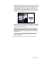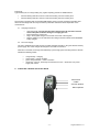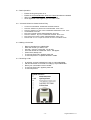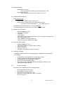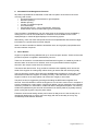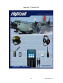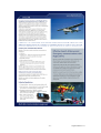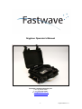
1
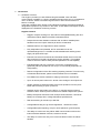
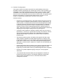
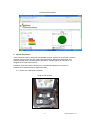
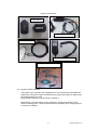
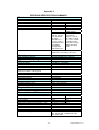
Gryphon Operator’s Manual
Fastwave Communications Pty Ltd
T:+61 (0) 8 9381 5353
F: +61 (0) 8 9381 5885
E: [email protected]
www.fastwave.com.au
-1-
Gryphon Manual V1.7
1. Introduction
1.1. Hardware Overview
The Gryphon provides you with GPS tracking and satellite voice and SMS
communication capability in a single, portable and autonomous unit. It is intended for
use in a vehicle, vessel or aircraft in regions with no radio communications or
beacon coverage.
It also has a wireless panic button to send distress messages via email and SMS to
designated recipients in any location in the world. These distress messages are also
displayed on the FastView monitoring console.
Gryphon features
•
Rugged, compact tracking unit, with internal rechargeable battery pack and
miniaturized Iridium Data/Voice/GPS combined antenna.
•
Dustproof and water resistant enclosure with an Iridium satellite phone
handset mount and 2 panic buttons per device as standard.
•
Headset interface via FlightCell Pro audio interface
•
Fully independent and portable, but for extended use can be
operated/charged from 11-32VDC aircraft/vessel/aircraft auxiliary power
supply via optional DC input .
•
External connectors for antennas and handsets enable users to store the
device with the lid closed & locked down during operation. This enables
crews to secure the device safely and still operate it to its full capability
•
Extended battery life with a minimum of 24 hours of operational use
(potentially 36hours operational use & up to 72 hrs standby dependant on
configuration)
•
Remote configuration of the GPS tracking reporting intervals. This is done by
a Fastwave administrator, please contact Fastwave for more details.
•
Free SMS to the device handset for relaying instructions, requests etc.
•
Up to 16 remote panic buttons for aircraft crew carriage in Anti Hijack role
•
Simple confidence checks discreetly ensure unit operation from the panic
button without having to open up the unit.
•
Handset can be used locally to the device, or remotely with an optional
extension cable. Antenna ports are external to enable multiple user options
•
Battery level/power indication levels & simple instrumentation. Unit sends
battery low message when voltage falls below specified level.
•
Real time tracking for aircraft up to 50k feet
•
Configurable tracking ID, eg vehicle registration , aircraft tail number
•
Configurable speed reporting, ie kph or knots (based on ground speed)
•
The ability to conduct two-way Iridium SMS communications to/from the
Iridium handsets between vehicles, vessels or aircraft
•
The ability to conduct two-way voice communications to/from the Iridium
handset
-2-
Gryphon Manual V1.7
1.2. FastView Tracking System
The Gryphon obtains its location information from GPS satellites via the dual
GPS/Iridium antenna supplied and an internal GPS receiver. This information is retransmitted via an Iridium satellite transceiver within the unit to the Iridium satellite
constellation, which then relays the information to the gateway in Arizona, from
where it is sent to the FastView secure servers for client access. This typically takes
less than 30 seconds. An overview of the system is shown on Annex A. The
Gryphon is supplied fully programmed to be used on this system.
FastView features
•
Fastview is a multi award winning, web based asset tracking and monitoring
system, hosted by Fastwave Communications in secure, offsite servers. To
use the system, a computer with internet access and Google Earth installed
is required. Clients are provided with secure login facilities by Fastwave on
commencement of their service contract. Unlimited numbers of vehicles,
vessels or aircraft can be tracked simultaneously by unlimited number of
users. Clients have access to a complete range of administration facilities, eg
assigning access privileges, setting unit ID’s, eg call signs etc.
•
Automatic location updates on FastView tracking system are can be set at
intervals from 1 minute up. A typical interval is every 20 minutes for vehicles,
and 10 minutes for aircraft. However, this is dependent on the client’s
operational and budget requirements, and can be varied as required for
individual units.
•
The FastView tracking system can display client specific GIS data, maps,
charts, facilities, waypoints and other reference points as overlays on the
Google Earth interface. It can automatically send email and SMS messages
to the client’s control centre ( or any other client specified recipient) when
destinations, restricted zones, waypoints or airspace are entered/exited (see
Geo-fencing)
•
FastView will display alerts and deliver various levels of applicable alarms via
email and SMS to the client when activated (eg distress alarm) or when
triggered by pre-determined events (eg outside designated area or airspace)
•
Fastview can upload simplified mapping overlays for country/regional
observation
•
Accurate historical travel information can be displayed on FastView for
individual and groups of assets. The FastView database can generate
various reports, exportable to Excel, for individual asset and fleet
management purposes
-3-
Gryphon Manual V1.7
Example Images from FastView System
Flight track across the Mediterranean
Light aircraft flight path across Pacific Ocean
Low-level survey aircraft tracking
-4-
Gryphon Manual V1.7
FastView Web Interface
2. System Preparation
These instructions are for fitting the transportable Gryphon system into an aircraft. It must be
stressed that at no point are any components permanently attached to the aircraft. This
system is designed as a flexible tracking solution for multiple types of aircraft and is not
designed to be a permanent fixture.
Fastwave recommend ground testing prior to operational deployment to ensure no
interference is experienced by cockpit instruments.
2.1. Outline of the Equipment Supplied:
Gryphon with lid open
-5-
Gryphon Manual V1.7
Gryphon Components
Panic alarm
Power Cable and Adapter
Antenna & cable
Iridium Satellite Handset
DC Input Smart Charger
2.2. Gryphon system assembly
The system can be stored in the ruggedised carry case almost fully assembled and
these basic instructions need to be carried out to prepare the system for deployment
each time the device is used.
More detailed instructions can be found in Chapter 3.
Before fitting, check the battery is fully charged by checking the indicator in the
fascia is showing green. This will provide maximum operating time. Charging advice
is covered in Chapter 4.
-6-
Gryphon Manual V1.7
Assemble the system in the following order:
Step 1: Ensure power is OFF
Step 2: Connect antenna coax cable to the antenna if not already connected
(These are colour & size coded to ensure the right connector are mated)
Step 3: Connect other end of antenna cable to Gryphon
-7-
Gryphon Manual V1.7
Step 4: Connect handset cable in RJ11 socket
3. Fitting the System
3.1. Installing the Gryphon in an aircraft
The Gryphon is configured to automatically send location updates to the Fastwave
System at pre-determined intervals when in flight. These cannot be changed on the
unit. If the interval needs to be changed, this has to be done via the FastView web
interface, or by contacting a Fastwave Administrator.The device is very sensitive to
GPS & Iridium signals, however it has its limitations. For optimum operation, the
antenna must have maximum exposure to the sky. See Step 4 below for more
detail. It will not work indoors, through metal, strengthened/ armored/ tinted glass or
some types if plastic. The white upper side of the antenna should have a clear view of
the sky at all times.
Step 1: Find a suitable place to locate the Gryphon in the aircraft. A
suggested ideal area is behind the Flight Engineers Console.
Step 2: Ensure all power is off – this is determined by ensuring that the toggle
switch is UP & the LED is not lit. Warning: Toggle switch lever must be
pulled UP to allow switch to be operated
Step 3: The handset can be mounted inside the case in it’s normal stowage
position, or remotely outside so the case lid can be shut. In either
configuration, it is best to keep the hand set in one of the cradles to
conserve battery power and ensure it rings when called. Gryphon is
supplied with an additional stand-alone cradle with can be fixed away from
the case if required.
Step 4: Mount the antenna on a cockpit window using the suction cups
provided. It is best to find a window that is not:
•
The forward windshield if constructed of strengthened glass
•
Heated by metallic elements
•
A location that will cause obstruction for crew to safely perform their
duties.
-8-
Gryphon Manual V1.7
Ideally the device needs a 180 degree field of view of the sky in a central
cupola or similar area. In this case, the standard 2 x suction cup mounts
are designed to provide maximum grip on smooth, airtight surfaces. If a
central cupola is not available the you can mount the antenna on a
vertical window pane. The antenna should be mounted so that it faces
upwards, parallel to the sky in normal flight (as much as possible) and
the cables should point downwards inside the aircraft, as shown below.
This ensures correct polarization.
Mount the antenna in as central location as possible on the windowpane.
These should be an equal distance around the outside of the antenna to
the sides of the window pant to ensure minimal reflection of signal s from
the metallic elements surrounding it.
IMPORTANT: If the antenna is to be mounted in an environment
that has surface temperatures then it is recommended that the
antenna is mounted at the last possible moment before take off to
prevent the equipment over heating whilst static on the ground in
direct sunlight.
6. Turn the Gryphon on. Toggle Switches fitted to this is unit is
latched. To operate the switch lever must be pulled UP to allow
switch to be operated.
The handset will show how the following sequence during initialization.
-9-
Gryphon Manual V1.7
First Screen
Second Screen
Third Screen
Fourth Screen
Fifth Screen
Once registered with the Iridium Network, the system is now installed and ready for use. It has
been programmed to transmit a GPS fix every ten minutes whilst in cruise flight as a default.
Note: The system can take several minutes from initial set up to register with GPS & Iridium
network and start transmissions to the Fastwave system. It is best practice to test the system prior to
fitting to an aircraft at least 15 minutes before use and then again once it has been installed to ensure
there are no factors affecting transmission.
3.2. Removing the system from an aircraft
•
•
•
•
•
•
The system should be removed from the aircraft in the reverse order:
Turn off the power. Toggle Switches fitted to this unit are latched. To
operate, the switch lever must be pulled UP to allow switch to be
operated
Remove the antenna suction mount from the airframe.
Disconnect the antenna cable from the antenna and case and stow
Remove the handset if plugged in externally, reseat inside & plug into the
internal socket
Recharge ready for the next flight. Charging advice can be found in Chapter
4.
4. Charging & Battery use
Gryphon has been designed specifically to provide extended battery life for operational use anywhere in
the world. The battery life is directly linked to how often phone calls are made, SMS sent and tracking
- 10 -
Gryphon Manual V1.7
interval set.
Typical battery life, for using tracking only, against reporting periods are detailed below.
•
•
5 minute tracking intervals 24 hours continuous tracking 72 hours stand by time
2 minute tracking intervals 18 hours continuous tracking 48 hours stand by time
The Gryphon is supplied with an integrated NiMH battery pack to provide exceptional operating time
with a low size/weight ratio and may exceed the parameters mentioned above dependant on the
circumstances.
4.1. Charging Instructions
•
•
•
•
Open the lid fully. The unit should not be charged if the lid cannot be raised to
ensure adequate ventilation during the charging process.
Ensure the device power is off.
Plug in the supplier charger to the socket on the side of the Gryphon
Plug the adaptor in to the wall socket and charge until the indicator shows GREEN &
is fully charged.
4.2. DC Power Supply
The unit is supplied with a smart charger to enable extended operation, using the vehicles auxiliary
power supply. The smart charger will charge the unit while it is turned on.
When first connected, the charger LED will briefly cycle through green-red-orange flash. It will then
indicate the following modes:
•
•
•
•
orange steady – charging
green steady – charge complete
green-orange-red flash – check connection
red steady – time out ,full charge not reached in 8 hours – disconnect from power
supply and re-start
5. Iridium DPL Handset Quick User Guide
LCD Screen
Cradle
Volume up/down
Menu up/down
- 11 -
Gryphon Manual V1.7
5.1. Basic Operation:
•
•
•
•
Ensure the Gryphon power is on
Ensure the Voicemail Number & Service Centre Numbers are entered
Wait until the handset is registered on the network
Once registered house appears you can make a call
5.2. Voicemail & Service Centre Number Entry
•
•
•
•
•
•
•
•
To enter the VOICEMAIL & SERVICE CENTRE Numbers:
Press the <MENU> key three times to MESSAGES. Press <OK>
Press the <MENU> key four times to MESSAGE SETTINGS. Press <OK>
At VOICEMAIL Press OK.
Enter the Voicemail number 00881662990000. Press OK.
Press the <MENU> key once to SERVICE CENTRE. Press <OK>
Enter the Service Centre number 00881662900005. Press <OK>
Press & hold <C> for a couple of seconds to return to the Main screen.
5.3. Making a Voice Call:
•
•
•
•
•
•
•
Remove handset from cradle/holder
Enter the number you wish to call
Use the + symbol, or 00 prefix, for all calls
Once the number is entered the “Call?”, will appear
Press OK to attempt call
To end call “End Call?” appears press OK
To end call press C or replace handset in cradle
5.4. Receiving a Call:
•
•
•
•
•
In call alert, remove handset from hang up cup/cradle/holder
Call should answer if removed from hang up cup/cradle/holder
Direct your conversation to the handset
To end call “End Call?” appears press OK
To end call press C
- 12 -
Gryphon Manual V1.7
5.5. Special Features:
•
•
Adjust Earpiece volume:
o
Press up and down volume key on handset whilst on a call.
Adjust Ringer Volume:
o
Press up and down volume keys, whilst not on a call
5.6. Satellite Dialing Sequence:
For all calls you must:
•
•
Use international dialing prefix, either 00 or +
Always enter the country code, area code & phone number
o For Iridium to Iridium calls dial 00 or +, then 8816 xxx xxxxx
For example 001 XXX XXX XXXX or + 1 XXX XXX XXXX
To contact Emergency Services, dial 112 or Refer Service Provider
5.7. Dialing From Phone book:
•
•
•
•
•
•
•
Press the MENU UP arrow
“Find Name?” appears
Press OK
“Enter Name?”
Enter the key of the corresponding letter (2 for A) Or Press OK and then use
the across arrows to scroll
“Call?” appears, press OK to make call
Press C to go back or MENU button again
5.8. Using The Menu System
•
•
•
•
•
Press the MENU key once
Keep pressing Menu to scroll through the options
Press OK to select
Press C to go back
Use MENU scroll and arrow keys for options
5.9. Reading a message:
A message is received when the envelope appears or Message Received appears
on the display
•
•
•
•
•
5.10.
If message Received appears then simply follow prompt.
If only the envelope is showing then press MENU
Press MENU key until “Messages?” appears
Press OK to select message options
From here you can read, delete and save messages Voicemail & Text
Messages will appear like this
Deleting Message:
A message can be deleted from in the message options
•
•
•
•
•
From “View Options?” select OK
Press MENU to scroll the options
From here you can delete, store, edit
Press OK to confirm selections, press C to go back
Press C to go back
- 13 -
Gryphon Manual V1.7
5.11.
•
•
•
•
•
•
•
•
•
•
•
•
Creating a Text Message SMS:
Press the MENU button to Message View Options?”
Press OK to select
Press MENU until “Message Editor?” appears
Press OK to select
Write message using keypad.
Press OK
Select options, “Send?” or “Store?”
Press OK to select
To send enter the phone number or view phone book
Send or Save message?
Press OK
Press C to go back
Send free text message to Gryphon Handsets
5.12.
This service is designed to avoid the cost of calling the Gryphon satellite
phone from a landline or cellular phone.
•
•
•
•
•
•
•
Open up a web browser on a computer connected to the internet
Navigate to www.fastwave.com.au
Follow the “send free message” link
Fill in the required Gryphon phone number and type the message
Click Send when you have finished
Your free SMS has been sent to the required Gryphon
It may take up to 15 minutes for the message to be delivered
** IMPORTANT: Please be aware that you will not receive SMS messages
until you have registered your region with the Iridium network. The
Global Iridium network is setup with Message Delivery Areas (MDA) or
REGIONS.
To do this: Set up a call by either calling your voice mail or making a call
to another phone number or simply dial 1234 for a free test call . This
will then allow the Iridium network to become aware of your location and
all outstanding SMS messages will be delivered to your Gryphon**
- 14 -
Gryphon Manual V1.7
6. Handset Trouble Shooting:
Message
Call failed – system
busy- weak signal
Blocked
Causes
The phone is unable to access
the satellite network due to:
•
poor signal strength
and/or
•
system congestion
If SIM card Pin is entered
incorrectly more than three
times in a row, the SIM card
will be blocked - this will
require the PUK code from
your service provider
•
•
Action
check antenna has
good view of sky
wait a few minutes and
try again
From the front screen:
Press **05*
Press OK
Enter PUK code
Press OK
Enter new Pin number
Press OK
Confirm new Pin number
Press OK
7. Geo fences
Geo fences can be set up for the Gryphon to aid Air Corridor compliance & automatically
notify if aircraft deviate into or out of restricted airspace.
Geo fences will trigger text alerts via SMS and Email to predefined distribution lists, and a
visual alert on Google Earth.
An example of an aircraft flying within a geo fence is shown below:
Contact Fastwave for more information on setting geo fences up.
- 15 -
Gryphon Manual V1.7
8. Automated Fleet Management Function
All position reports/alerts are delivered in near real time (within 30 seconds of the event
occurring) and contain:
•
Air speed reporting (in knots based on groundspeed)
•
Direction reporting
•
Altitude reporting
•
Location in Latitude/Longitude
•
Time Date Stamp
•
Configurable unit ID – can be Tail Number, Pilot ID etc
•
Profile of alert events recorded within geo fenced areas
The information is available as a one click event view on the tracking screen–available by
clicking the Icon next to the Tail Number on FastView.This is available on the current
displayed flight, or historical flights displayed on the tracking system.
Alternatively, users can down load specific Excel format spreadsheets with the device flight
information for a specific date for further analysis
Alerts can also be emailed or SMS’d to authorized users, and a graphic popup delivered to
the user interface if required.
9. Panic Buttons
Gryphon is capable of being affiliated with up to 16 remote panic buttons. These can be water
proofed if required, or supplied in standard Key fob form.
These can be issued to crew aboard an aircraft fitted with Gryphon, to enable any holder to
raise the alarm in the event of an incident, such as a hijack situation with the Gryphon
secured in the cockpit or else where in the aircraft.
The buttons are dual function. They provide a confidence test capability which shows the
holder if the Gryphon is working okay without having to interact with the device physically.
This is achieved by pressing and holding the GREEN buttons together for 5 seconds. If the
LED flashes it means the Gryphon is working correctly. If the LED does not it means the
Gryphon is either out of range (about 100 meters line of sight) or has a fault.
The panic function is triggered by pressing and holding the RED buttons together for 5
seconds. If the LED flashes it means the Gryphon is now in Panic mode. Once in reception of
a panic message from a panic button, Gryphon will deliver a priority message to the FastView
monitoring console as a visual alarm, emails and SMS to designated recipients .The tracking
will also be updated every 60 seconds until the device is reset by SMS or physically reset by
power cycling the Gryphon using the power switch.
Fastwave recommends testing remote panic buttons in likely area so if the aircraft prior to
operational deployment to confirm users are happy with the functionality as it may vary
considerably inside different airframes.
- 16 -
Gryphon Manual V1.7
10. Fault Finding
Problem
Gryphon not working
FastView software system
shows no devices
FastView software system
shows no devices
Panic Buttons don’t work
Handset isn’t working
Possible cause
Action
No power to unit
If Gryphon shows no power Check:
:Battery Meter shows a charge
:Toggle Switch is ‘ON’
:Handset shows a display
:If not, battery may be flat. See below.
Battery flat
A flat battery will prevent the unit working. In this situation:
:Ensure Toggle Switch is ‘OFF’
:Raise Lid
: Charge unit by plugging in the wall charge/adaptor
:To check that the unit is charging by observing the dual color
LED on the charger. When the charger is initially plugged into the
unit, the LED goes to a RED color (CHARGING). Once charging
is complete, this LED will change to GREEN (FULL)
Battery Faulty
If the unit will either not charge (charger LED will not indicate
RED) or the POWER switch is in the ON position after the unit
has been charged fully, there is a possible battery or other fault
with the unit. Return to Fastwave for repair.
Wait at least 10 mins for unit to register on the system, especially
in brand new units or location.
Iridium delay
Aircraft not on the
Fastwave system
Ensure the Fastwave administrator has input the aircraft details
and allocated it to the Gryphon Device
Unit not fully activated
If the device does not show on the system after around 30
minutes and the Handset has not registered with Iridium (Chapter
3) check with your service provider that the SIM and Device are
activated.
Antenna problem – I know
it’s been registered on
Iridium, but still no signal
Check:
:Antenna orientation/polarisation–coax should be facing down
:Antenna location–uninstall and give clear view of sky outside of
aircraft if necessary.
:Antenna sucker pad side should have a clear view of the sky.
:Coax’s are undamaged and correctly fitted
:If above OK replace antnna and coax with another to determine
if it’s the Gryphon or the Coax
Check the button has power by holding the Green buttons down together for 3 seconds and
observe that the RED led on the PANIC REMOTE is lit while holding BOTH the
GREEN buttons down. After three seconds, release the buttons and the RED LED should then
flash several times to confirm that it is communicating with the Gryphon.
Ensure the button has a line of sight to the device to test it.
Ensure the Gryphon is on, and able to receive Panic button signals
Check it’s plugged in to the Gryphon, either on the fascia or external socket
Ensure the Gryphon has a charge in order to power the handset
Ensure the Gryphon is turned on.
See Annex B for more detailed information Iridium Handset
- 17 -
Gryphon Manual V1.7
11. Fastwave System Overview
Client
Control
Centre
Fastwave
Servers
Client control
centre
12. Headset Interface
The Gryphon is compatible for use with civilian headsets via the optional Flightcell Pro (see
Appendix 1 for details)
To use the Flightcell Pro with the Gryphon, please refer to the following procedure:
•
•
•
•
•
•
Read the Flightcell manual first and understand how to adjust audio levels and ring
alert tones available with the FC-Pro
Read the Iridium DPL handset guide in section 5above.
Using the supplied 3.5mm to 3.5mm curly audio cable (can be identified as it has a
white band at one end) connect one end to the FC-Pro socket labelled Sat Phone.
The other end should be connected to the 3.5mm socket that is located just above
the battery level indicator on the front panel of the Gryhon.
Turn the Gryphon on and perform some test calls.
NOTE: When the 3.5mm cable is plugged into the Gryphon the DPL handset
microphone is DISCONNECTED. However, the DPL handset speaker will remain
connected.
It MUST be noted that placing the Gryphon DPL handset in the HANG-UP cup will
NOT terminate a call. All calls MUST be terminated (hung up) by pressing the “OK”
key on the DPL handset. Answering a call is same procedure. Refer also to the
picture below for other key sequences
- 18 -
Gryphon Manual V1.7
•
•
The hang up cup on this Gryphon has been especially modified so as to allow a call
to continue even though the DPL handset has been placed back into the handset
Battery life may be reduced slightly as a result of this modification
- 19 -
Gryphon Manual V1.7
Appendix 1: Flightcell Pro
- 20 -
Gryphon Manual V1.7
- 21 -
Gryphon Manual V1.7
Appendix 2
GRYPHON SPECIFICATION SUMMARY
Electrical
Power
Power Consumption (Average Current)
11-32VDC 2.5A
Input Voltage
12V
24V
0.58 A
0.27 A
0.73 A
0.35 A
Ni-MH chemistry, 9.6 Vdc, 4 Ahr
AC charger
Optional DC input
Smart Charger
Ni-MH
Ni-MH multi mode
INPUT: 100-240
programmed.
Vac, 50-400Hz,
INPUT: 11-32 Vdc,
25 watts.
25 Watts. OUTPUT:
OUTPUT: 9.6 9.6 -12.6 V, 2 Amps
12.6 V, 2 Amps
Constant Current,
Constant Current, zero delta V charge
zero delta V
detect with safety
charge detect
timer.
with safety timer
Standby Mode
Talk/Transmit Mode
Battery
Battery Charger
Protection
Battery pack – embedded poly switch
Electronics – fast acting 5 Amp fuse
Compliance
EMC Compliance (device)
Transceiver
C-Tick (Australian Govt Approval)
FCC Q639522AC, CE
RF Interface (L-Band Transceiver)
Frequency Range
Average Power
Average Power
Receiver Sensitivity
Receiver Spurious
Rejection at offsets >1MHz (typical)
Duplexing method
Oscillator Stability
Input/output impedance
Multiplexing method
1616MHz to 1626.5MHz
7W during transmit slot (max)
0.6W during a frame (typical)
-118.5 dBm at 50W (typical)
60 dB
TDD (Time Domain Duplex)
+/-1.5ppm
50 Ohms
TDMA/FDMA
Environmental
Operating temperature range
Operating humidity range
Storage temperature
-20c to +60c ambient
<85% non condensing
-40c to + 85c
Physical - Device
Weight (including antenna & cable)
Dimensions - case
5.2kg
27 x 24.6 x 12.4 cm
External Iridium/GPS Antenna
Iridium
GPS
1610-1626.5MHz
1575.42 +/-13
Hemispherical
Hemispherical
30W
1W
DC grounding
DC grounding
W 55.88 L 127.66 H 18.77
226 g
-55c to +85c
70,000 ft
>30 G’s
FAA TSO-C144, DO-160D, MIL-C-5541,
MIL -E-5400, MIL-I-45208A, MIL-STD810, SAE J1455
Frequency
Radiation Pattern
Power handling
Lightning protection
Size mm (exc magnetic mount/suction cups)
Weight
Environmental - Temp
Altitude
Vibration
Federal & Military Specifications
- 22 -
Gryphon Manual V1.7