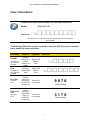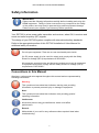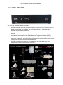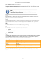
1
Remote Satellite Terminal RST100 Installation and User Manual BEAM Communications Pty Ltd RST100 INSTALLATION & USER MANUAL Remote Satellite Terminal RST100 Installation and User Manual BEAM Communications Pty Ltd 8 Anzed Court, Mulgrave, Victoria, 3170, AUSTRALIA Information furnished by BEAM Communications Pty Ltd (BEAM) is believed to be accurate and reliable. However, no responsibility is assumed by BEAM for its use, or for any infringement of patents or other rights of third parties, which may result from its use. No license is granted by implication or otherwise under any patent or patent rights of BEAM. BEAM reserves the right to change specifications at any time without notice. Copyright © 2008 BEAM Communications Pty Ltd. All rights reserved Product name: Manual revision: Part Number: Release date: RST100 User & Installation Manual Version 06 USRMAN000206 February 2011 2 RST100 INSTALLATION & USER MANUAL Package Contents Check that your RST100 package contains: 1 x RST100 unit 1 x Universal plug-pack power adapter, 110-240V AC 1x DC Power Cable (for use only on 11 – 32V DC input) 1 x 9-pin-to-9-pin RS-232 cable (Male to Female) 1 x User Manual (printed) Allen Key, screws & washers 2 x Mounting Brackets Optional Accessories The following optional accessories are available for your RST100. o o o o o o o FX2600 – Fax Adapter RST050 - Battery Backup Sub-System RST978 - In-vehicle Hands-free kit RST970 - Intelligent handset Cable Kit Antenna External Ringer Additional Information For the latest in supporting software and documentation for RST100 RemoteSAT please visit www.beamcommunications.com/support/RST100 See your Service Provider for pricing and availability of these quality accessories. 3 RST100 INSTALLATION & USER MANUAL User information Please record your serial number here for future reference: Model: Serial no.: BEAM RST100 This number can be copied from the white shipping label on the RST100 box Eg. 100A2800 The following PIN codes may be required to use your RST100, please complete these details for future reference. PIN Name SIM PIN Supplied by your Service Provider PUK Supplied by your Service Provider User PIN Supplied here Supervisor PIN Supplied here Function Symptom Unlocks SIM card to enable calls to be made Signal LED flashes Red Unlocks a locked SIM card Signal LED flashes Red Enter PIN on console 9876 Enter PIN on console 3170 Allows access to user menu of RST100 via log port Allows access to supervisor menu of RST100 via log port Your PIN Default setting Default setting 4 RST100 INSTALLATION & USER MANUAL Contents PACKAGE CONTENTS .......................................................................................................................... 3 OPTIONAL ACCESSORIES ........................................................................................................................ 3 USER INFORMATION ............................................................................................................................ 4 CONTENTS ............................................................................................................................................. 5 SAFETY INFORMATION ........................................................................................................................ 6 CONVENTIONS IN THIS MANUAL ............................................................................................................... 6 ABOUT BEAM COMMUNICATIONS ..................................................................................................... 7 ABOUT THE RST100 ............................................................................................................................. 8 GETTING STARTED ............................................................................................................................. 11 W HAT IS A SIM CARD? ......................................................................................................................... 11 SIM CARD PROTECTION ....................................................................................................................... 11 INSTALLING & REMOVING THE SIM CARD .............................................................................................. 11 INSTALLING RST100 ........................................................................................................................... 13 MOUNTING THE RST100 ...................................................................................................................... 13 CONNECTING THE AC POWER CABLE .................................................................................................... 15 CONNECTING THE DC POWER CABLE.................................................................................................... 15 CONNECTING A HANDSET OR OTHER POTS/RJ 11 DEVICE..................................................................... 16 CONNECTING THE OPTIONAL INTELLIGENT RST970 HANDSET ................................................................ 16 CONNECTING A LAPTOP OR PC ............................................................................................................. 17 CONNECTING TO THE LOG PORT ........................................................................................................... 17 CONNECTING AN ANTENNA CABLE ........................................................................................................ 18 INSTALLING THE EXTERNAL ANTENNA .................................................................................................... 18 RJ11 / POTS EQUIPMENT ................................................................................................................... 19 PIN CODES.......................................................................................................................................... 19 MAKING A PHONE CALL .................................................................................................................... 20 LOGGING ON TO IRIDIUM NETWORK ....................................................................................................... 20 MAKING A PHONE CALL ......................................................................................................................... 20 ACCESSING VMAIL AND SMS ON YOUR RST100 .................................................................................... 21 VOICEMAIL ........................................................................................................................................... 21 SMS - SHORT MESSAGE SERVICE ........................................................................................................ 21 CONNECTING YOUR RST100 WITH A PABX........................................................................................... 21 CONFIGURING SMS-POTS FEATURE.................................................................................................... 22 CONNECTING AN CONFIGURING AN SMS-POTS TELEPHONE .................................................................. 23 REMOTE CONFIGURATION..................................................................................................................... 23 ACCESSORIES & OPTIONS................................................................................................................ 24 BEAM RST970: INTELLIGENT HANDSET ............................................................................................... 24 FX2600 : FAX ADAPTER ....................................................................................................................... 24 SPECIFICATION SUMMARY ............................................................................................................... 25 RS232 SPECIFICATION ....................................................................................................................... 26 PHYSICAL CONNECTION........................................................................................................................ 26 RS232 PORT SIGNAL SUPPORT AND HANDSHAKING .............................................................................. 27 RS232 PORT ELECTRICAL PARAMETERS .............................................................................................. 27 TROUBLESHOOTING .......................................................................................................................... 28 BEAM W ARRANTY CONDITIONS ........................................................................................................... 31 5 RST100 INSTALLATION & USER MANUAL Safety Information IMPORTANT! Please read the following information carefully before installing and using this BEAM equipment. Failing to follow instructions may compromise the safety of the product and may result in personal injury and/or equipment damage. Please consult your supplier if you have any further questions. Your RST100 is a low power radio transmitter and receiver, when ON, it receives and sends out radio frequency (RF) signals. The design of your RST100 system complies with international safety standards. Refer to the appropriate section of this RST100 Installation & User Manual for additional safety information. Warning: Do not open equipment. There are no user-serviceable parts inside. If a DC power supply is to be used, its output must comply with the Safety Extra Low Voltage (SELV) requirements of IEC60950. All connectors except the Line and Accessory sockets must only be connected to equipment ports which comply with the Safety Extra Low Voltage (SELV) requirements of IEC60950.” Conventions in this Manual Warnings, cautions and notes appear throughout this manual and are represented by following conventions. Warning: This symbol and associated text indicate a warning note providing information to prevent personal injury or damage to equipment. Note: This symbol and associated text indicate a note providing general operating information. Interference: All wireless phones may get interference, which could affect performance. Record: Write details of your unit for easy reference when required. Ideal when troubleshooting. 6 RST100 INSTALLATION & USER MANUAL About BEAM Communications Beam Communications, a wholly owned subsidiary of World Reach Limited (WRR), listed on the Australian Stock Exchange, is a world leader in design, manufacture and distribution of specialized communications equipment for the Iridium Satellite Network. Beam’s commitment to be at the forefront has continued to increase its share of the global satellite communications market. Its premium distribution network spans the world. Recognized as a leading provider of satellite communication solutions, Beam specializes in Voice, Data, Tracking and customized solutions. Beam develops innovative products and services to meet market demands and niche applications. Beam’s leading edge products are deployed in a wide range of vertical markets including Maritime, Transport, Government, Defense, Mining, Construction, Forestry, Emergency Services, Relief Aid, Telemetry and Rural Telephony. Supported by a dedicated team of professionals, Beam has developed solid relationships with its peers and network of distributors worldwide. Beam Communications Pty Ltd 8 Anzed Court, Mulgrave, Victoria, 3170, AUSTRALIA Web: www.beamcommunications.com Info: [email protected] Support: [email protected] Tel: +61 3 8588 4500 Fax: +61 3 9560 9055 7 RST100 INSTALLATION & USER MANUAL About the RST100 The RST100 - Remote Satellite Terminal: provides a reliable and cost effective telephone or data service connection when a wired connection is not available, via the Iridium network — a satellite-based, wireless communications network. allows the connection of standard telephone handsets and other telecommunications devices. emulates the functionality of the Public Switched Telephone Network (PSTN). includes two wire voice connections, a Hayes compatible modem, providing a serial socket for a computer, a socket for the connection of a plug-pack type mains power supply and a connection to an external antenna. provides a serial control interface and audio input and outputs by way of the transceiver’s control and connection interface. 8 RST100 INSTALLATION & USER MANUAL The Front Panel 1 2 3 4 5 Status LEDs 1. 2. 3. 4. 5. Power Voicemail waiting* SMS waiting Call status Signal strength * Subject to network availability The Rear Panel A F G B C H A: RJ11 Phone Socket B: Parallel RJ11 Phone Socket C: Intelligent Handset D: Comm (Data) Port E: Reset Button F: Iridium Antenna Port G: DC Power Input H: Remote Status Indicator – Not used I: Log Port – Configuration Port using BEAM Management System 9 D I E RST100 INSTALLATION & USER MANUAL The RST100 Status Indicators The status indicators are located on the front panel of the RST100. The LED lights on the front panel show the RST100 status. Note: The LEDs will blink in different combinations to indicate transmission status, signal strength and power. Power When powering up the RST100, the Power LED flashes while it carries out internal selfdiagnosis, and then illuminates a steady green Vmail The Voicemail LED flashes to indicate message(s) are waiting in your voice mailbox to be retrieved. This service is subject to network support and not available from all providers. SMS The SMS LED flashes to indicate an SMS message is waiting. Call The Call LED indicates the status of the call, which can be: • In Call • Waiting to connect • Incoming call Signal The Signal LED indicates the strength of the signal from the Iridium network at your location. This LED displays different colours to indicate the strength of the RF (Radio Frequency) signal and different on/off conditions to indicate the terminal status. Signal LED colour Signal strength Flashing RST100 is registering with the network – please wait Green Strong Orange Acceptable Red No signal, or is not registered on the Iridium network For further information about these aspects, refer to the troubleshooting section of this manual. 10 RST100 INSTALLATION & USER MANUAL Getting Started What is a SIM Card? A SIM Card is a Subscriber Identity Module (computer chip) that contains identity information for accessing the Iridium network. It functions as the digital memory of the RST100 and also stores your personal information, including received SMS messages. SIM Card Protection Handle the SIM card with care, avoid exposing the card to static electricity, water or dirt. Scratching or bending the SIM card will damage the card or its metal contacts. Installing & Removing the SIM Card The SIM card is stored in a recess in the SIM card compartment located at bottom of your RST100. If your Service Provider has not installed the SIM card for you, follow these steps to install it. Warning: Make sure the RST100 is switched off before you insert or remove the SIM card. If you do not, the memory on your SIM card and or the SIM card itself may be damaged. 11 RST100 INSTALLATION & USER MANUAL Step 1: Using a Phillips-head screwdriver, remove the holding screw and keep it in a safe place. Step2: Slide-open the compartment cover. Step 3: Remove the screws with the Allen Key provided to expose the SIM Holder of the RST100 Step 4: Gently insert the SIM card into the slot making sure that the golden connectors are facing downwards Step 5: Replace the cover and secure with Allen screws Step 6: Slide the compartment cover back into place Step 7: Secure the cover with the holding screw removed in Step 1(above). 12 RST100 INSTALLATION & USER MANUAL Installing RST100 This chapter explains how to install the RST100. Warning: Make sure the RST100 is switched off before you connect any cables. If you do not, the RST100 may be damaged. Note: Before you install the RST100, determine if the unit is preconfigured or needs customer configuration. Mounting the RST100 The RST100 comes with two (2) right angle brackets that allow mounting for mobile and fixed positioning. Note: To ensure a secure installation: 1. 2. 3. 4. 5. Mount the RST100 on a clean, even surface. Clean the mount surface of the RST100. Use the correct type of screws (as supplied). If mounting on wood, ensure wood is structurally sound. Leave enough room around the RST100 to allow easy access to the rear panel. 6. Do not install the unit in a permanently concealed area. Access must be possible in the event future service be required. The mounting brackets provide for two mounting methods: A: Drop-in (inside corner) mount. B: Flush (outside corner) mount 13 RST100 INSTALLATION & USER MANUAL Mounting the RST100 unit (continued): Step 1: Attach the two (2) mounting brackets securely to a suitable structure making sure the space between the brackets is wide enough to smoothly slide in the RST100. Step 2: Secure the RST100 to the mounting brackets using supplied screws. Step 3: Carefully slot the RST100 between the two mounting brackets and secure with the retaining screws. 14 RST100 INSTALLATION & USER MANUAL Connecting the AC Power Cable 1. Make sure the AC power switch supplying the RST100 power pack is OFF. 2. Plug in the power cable into the power jack located on the rear panel of the RST100. 3. Secure the cable by tightening the plug collar. 4. Using a country specific PC Monitor or kettle cord connect this to the AC plug pack for accessing Mains power. Connecting the DC Power Cable 1. Connect the DC termination terminal of the cable to your DC power source 2. Plug the remaining end with the screw connector into the power jack located on the rear panel of the RST100. 3. Secure the cable by tightening the plug collar. 15 RST100 INSTALLATION & USER MANUAL Connecting a Handset or other POTS/RJ 11 device 1. Connect a telephone, answering machine or cordless phone into the Line or Accessory socket. This socket supports an RJ11 plug. Facsimile Messaging via a standard RJ11 connection is not supported on the Iridium Network – see your Service Provider to discuss the dedicated FX2600 Iridium Fax Unit or visit us at www.beamcommunications.com 2. The Accessory & Line sockets work in parallel Connecting the optional Intelligent RST970 Handset 1. Connect to the Iridium Intelligent Handset, if supplied, directly to the Handset socket of the RST100. Figure: RST970 Handset cable connected to Handset Port Only use the extension cables for this handset provided. Cables up to 30 metres in length are available; consult with your Service Provider. 16 RST100 INSTALLATION & USER MANUAL Connecting a laptop or PC 1. Plug the laptop cable into the Comm Port of the RST100. Figure: Serial cable connected to Comm Port For more information on accessing Iridium Data Services with your RST100, please refer to the Beam Data Guide (available at www.beamcommunications.com) Connecting to the Log Port 1. Plug the laptop cable into the Log Port of the RST100. Figure: Serial cable connected to Log Port The Log Port should only be used for configuration and control of the terminal equipment. The Log Port cannot be used for communications or data services. The Log Port can also be used when using a BEAM Alert/Monitoring Device, refer to the instruction provided with the accessory device for configuration and installation. 17 RST100 INSTALLATION & USER MANUAL Connecting an Antenna Cable 1. Plug the antenna cable into the antenna jack located on the rear panel of the RST100, as shown below. Secure this cable by tightening the connector collar. 2. The specified cable being used must not exceed the Iridium 3dB maximum loss rating. This will ensure maximum performance of your RST100. Refer to your Service Provider for full details or to purchase an approved cable. Figure: Antenna cable connected to a RST100 Installing the External Antenna Refer to the separate “Iridium Antenna Installation Guide” for complete instructions. This guide is supplied with your RST100, or available for download at www.beamcommunications.com 18 RST100 INSTALLATION & USER MANUAL RJ11 / POTS Equipment The RST100 supports: multiple variations of standard telephone equipment including: standard corded, cordless, multiple handset cordless, answering machines, and other external ringing devices. a telecommunication standard of 3REN, which allows it to support multiple extension of the line. long cable runs off the RJ11 socket. This provides flexibility for installation as well as running long line distances from power in remote environments. most RJ11 equipment that can be purchased in most countries. It is advisable to purchase equipment that is endorsed or certified by the telecommunication authority in your country. PIN Codes To activate your RST100 to make and receive calls, you may need to enter a PIN code, described below. RST100 Signal LED Flashing Red LED Flashing Red LED Constant LED Handset tone Distinctive dial tone: two tones of equal length Distinctive dial tone: high tone is longer than low tone Normal dial tone Action required Enter four digit SIM PIN and await a change of tone (up to 10 seconds), then hang up. When successful the phone will register and proceed with normal use Enter the PUK code, await a change of tone (up to ten seconds) and hang up. When successful the phone will register and proceed with normal use No action required The PUK code is required to be entered if the SIM PIN is entered incorrectly 3 times in a row. The SIM card will be permanently disabled if an incorrect PUK is entered 10 times in a row. 19 RST100 INSTALLATION & USER MANUAL Making a phone call Logging on to Iridium Network With the power turned on, the RST100 will attempt to register with the Iridium network. The Signal LED uses colours to indicate how strong the Iridium signal is at your location. Signal LED colour Signal strength definition Green Strong Orange Acceptable Red No signal, no calls possible refer to “Troubleshooting” section In most cases the indicator will show green after a short period of approximately 15 seconds – orange indicates an acceptable but marginal signal strength. If the indicator remains solid red, there is a problem with the installation and/or the SIM card – calls cannot be made or received. To resolve this situation refer to “Troubleshooting” section of this manual. Making a phone call To successfully make a call on the Iridium network, you need the following: o Dial tone on the telephone handset o Call LED must shine green or orange continuously. Continue to make your phone call as you normally use a traditional phone, noting any dialling prefix instructions advised by your service provider. Once you have entered the phone number you will hear progress pips from the Iridium network. It can take up to 30 seconds for the Iridium network to connect a call, so a pause at this stage is not unusual. You will shortly hear the called party end ringing, or hear a busy tone and voice message indicating why your call was not possible. When the other party answers the Call LED will change from steady orange to flashing orange, indicating ‘call in progress’. This is a normal operating procedure. To end the call, hang up the handset. The Call LED light will then turn off. 20 RST100 INSTALLATION & USER MANUAL Accessing Vmail and SMS on your RST100 Voicemail When a Voicemail message has been received by the RST100 the Vmail LED will flash. The LED will stop flashing when the message has been cleared when the user connects to the Voicemail retrieval number programmed in the RST100. SMS - Short Message Service When an SMS has been sent to the RST100, the SMS LED will flash. This means that the SMS is ready to be read. The indicator is cleared when the SMS has been read and cleared from the RST100 memory. Note: Refer to the RST100 Configuration and Beam Management System Manual for details of how to connect a PC to the RST100 to read and send SMS messages. Connecting your RST100 with a PABX The RST100 RJ11 port presents as an FXS line, that is, it looks like an exchange or central office line to a standard DTMF telephone attached to the RJ11 analog port. If instead of a standard telephone, a PABX is connected, then the RST100 is performing the role of the network trunk as shown below: Call Progress Initiate incoming call FXS Sends ring to PBX Indicated by configured service tones Detects off-hook rom PBX Call Progress state Detects outgoing call from PBX Progress state Signalling in-call Sends dial tone to PBX Detect disconnect Detects on-hook from PBX DTMF The RST100 RJ11 default port setting is set to an “International Default” to operate out-ofthe-box with most phones and PABXs available. Within this International Default the line impedance is set to 600 Ohms and the levels in the up and downlink directions to suit the expected deployment scenarios. Specific implementations and terminal equipment may require adjustment of these parameters in association with your Service Provider. 21 RST100 INSTALLATION & USER MANUAL Configuring the RJ11 port parameters The ability to configure the RJ11 port parameters is one of the major features of the RST100. Port parameters can be configured using the BEAM Management System (BMS). The BMS allows the configuration of: • • • • Dialled number processing (to support crew calling and specialised applications) Line settings such as dial tone frequency and sound (in order to make the RST100 sound like any other phone in the network) Gain settings (to allow optimisation for short and long copper tails up to 500m) Impedance (to accommodate a large range of terminals equipment including PBXs) This ability to adapt the RST100 to particular applications opens up new areas of use in: o Crew Calling o Rural Community Centres o SOHO use o Universal Service Obligation activities. The RST100 is designed to support multiple phones in parallel, and can operate with many common calling card platforms allowing the creation of specific solutions to address specific needs. The configuration of the RJ11 interface is covered in the RST 100 Configuration and Beam Management System Manual, a companion to this document. Configuring SMS-POTS Feature Note: The SMS-POTS Functionality is only available on RST100 terminals with the following serial number type : Serial Numbers 100XXXX “ The serial number must contain an “A” to support the SMS-POTS Functionality. Refer to the User Information section to verify your RST100 is SMS capable. The RST100 can support the use of an SMS-POTS telephone to provide SMS messaging over the Iridium network without the need to use an Intelligent handset or a Computer to send and receive SMS messages. Using a POTS-SMS telephone it is possible to initiate an SMS message and send it to another Iridium user or to another cellular user (selected Service Providers only). Do not use an Intelligent handset in conjunction with an SMS-POTS telephone as the Intelligent handset and the SMS-POTS telephone cannot receive SMS messages sequentially. The SMS-POTS telephone will always have priority. Using an SMS-POTS telephone connected to an RST100 enables the handset to be run long distances from the RST100 over whilst still supporting SMS. Typically the Intelligent type handsets are limited to less than 10m/30’ whereas the SMS-POTS being on the RJ11 line will support 100s metres / 1000s feet. 22 RST100 INSTALLATION & USER MANUAL Connecting an configuring an SMS-POTS telephone An SMS-POTS telephone is easily connected to the RST100 terminal via the RJ11 connection (as mentioned in ‘Connecting a Handset or other POTS/RJ 11 device’ section of this document). Using the BEAM Management System the RST100 must be configured to enable the SMSPOTS feature. For more information, consult the RST100 Configuration and Beam Management System Manual, Available on the Beam Starter CD supplied with the terminal, or available for download from www.beamcommunications.com Remote Configuration The Supervisor Menu items are available for remote configuration via a combination of the Iridium Short Burst Data and or SMS services. Refer to your Service Provider on how to register for this service. To configure your RST remotely you will need to know its Phone Number, Supervisor PIN and International Mobile Equipment Identifier (IMEI) number. Multiple configuration commands can be sent in one SMS and the Supervisor PIN is only required once at the start. Once the PIN has been entered the top of hierarchy for each subsequent command in the message is the Supervisor menu. Digits can be entered exactly as you would enter them if you were on a directly connected terminal. All replies to your commands come back in one SBD email attachment and the original entered command is echoed back so you can see what each reply is for. Eg. To set the Ringer Frequency remotely to 20Hz Send an SMS to the phone number containing: RST RMT 3170 4120. Where RST RMT is the start of command message flag and 3170 is the default Supervisor PIN, 4 selects the tone menu, 1 selects ring frequency and 20 (Hz) is the new ring frequency required. The automatic confirmation reply returned via email will contain: From: <Iridium SBD Service (Tempe, AZ)> Sent: Tuesday, August 13, 2002 12:49 PM Subject: SBD Msg From Unit: 304050607080903 MOMSN: 23 Time of Session (UTC): Tue Aug 13 16:51:04 2002 Session Status: TRANSFER OK Message Size (bytes): 351 Unit Location: Lat = 59.372463 Long = 75.309806 CEPradius = 3 Message is Attached. The attached .sbd file returned will contain: 3170 OK Confirms PIN OK41 25 OK Advises content of parameter before the change is effected. 23 RST100 INSTALLATION & USER MANUAL Accessories & Options BEAM RST970: Intelligent Handset The RST100 is capable of supporting voice services on the Iridium network through the use of an (optional) Intelligent handset . This Intelligent Handset enables you to access Voice and SMS services over the Iridium network in conjunction with the RST100. Connecting an Intelligent Handset The Intelligent handset is easily connected to the RJ45 socket located on the RST100 Voice Data module. The unit should be powered off before inserting the connector and then reset once connected. An extension cable to the Intelligent handset can be sourced and used if required. FX2600 : Fax Adapter The FX2600 Fax Adapter allows you to send faxes from any Group 3 fax machine to anywhere in the world. The RST973 simply connects to the COMM Port on the RST100 module. The installation instructions supplied with the FX2600 kit will provide more detailed instructions. 24 RST100 INSTALLATION & USER MANUAL Specification Summary Electrical Power 11-32V DC 2.5A Plug-pack (if provided) 90-250VAC 50/60Hz input Power Consumption (Average) 12Volt Standby Mode 0.350A 0.165A Talk/Transmit Mode 0.515A 0.255A 24Volt Subscriber Line Interface Ring Equivalence Number 3 REN Impedance 600 Ω or TN12 2-wire interface Open circuit voltage -48V DC+- 5% Ring Voltage > 56V RMS EMC Compliance C-Tick and A-Tick, CE mark, RF Interface (L-Band Transceiver 9522B) Frequency range Average Power Average Power Receiver Sensitivity 1616MHz to 1626.5MHz 7W during a transmit slot (max) 0.6 W during a frame (typical) -118.5 dBm at 50W (typical) Receiver Spurious Rejection at offsets > 1 MHz (typical) 60 dB Duplexing method TDD (Time Domain Duplex) Oscillator stability: ±1.5ppm Input/output impedance 50 Ohms Multiplexing method: TDMA/FDMA Environmental Operating Temperature Range -15°C to +55°C ambient Operating Humidity Range <85% RH non-condensing Storage temperature -30C to +70C Weight 2.5 kg Dimensions 225 x 277 x 53mm Compliance Full IEC60945 25 RST100 INSTALLATION & USER MANUAL RS232 Specification The RST-100 is provided with two RS232 serial ports for log and data connection. Both are 9-pin D-type (female) sockets, wired DCE for connection to a standard PC with a 1:1 cable. Physical Connection The pin-out of both connectors is described in the following table: Pin Signal Direction Description 1 DCD RSTPC Data Carrier Detect 2 RXD RSTPC Received Data 3 TXD PCRST Transmitted Data 4 DTR PCRST Date Terminal Ready 5 GND 6 DSR RSTPC Data Set Ready (CTS and DCD) 7 RTS PCRST Request to Send 8 CTS PCRST Clear to Send 9 RI RSTPC Ring Indicate (7.5V on Log port) Signal Ground (Common) 26 RST100 INSTALLATION & USER MANUAL RS232 Port Signal Support and Handshaking On the data logging port, DCD and DSR output signals are related to DTR input and CTS is tied to RTS as shown. The Data port supports full software XON/XOFF handshaking on data (AT commands bypass this as standard for Hayes modems) or full hardware handshaking on RTS/CTS with DCD carrier indication. The Log port has no software handshaking support and hardware handshaking is loop-back only since the command set requires a minimal buffer. RS232 Port LBT Data Port Data Logging Port DCD DCD = DTR RXD RXD TXD TXD DTR DTR DSR DSR = DTR RTS RTS CTS CTS = RTS RI RI not connected RS232 Port Electrical Parameters The LBT “Comm” Port and Log Ports conform to the RS232 interface specification with the following parameters, however the Log Port communicates only at 9600. Parameter Specification Communication Rate 220 to 115,200 Baud Protocol 1 start bit, 8 data bits, no parity, 1 stop bit, asynchronous. Voltage Levels and Sensitivity RS232 compliant 27 RST100 INSTALLATION & USER MANUAL Troubleshooting This chapter provides information to help you troubleshoot problems you may encounter while running the RST100. Q No LEDs on RST100 A Check power is connected and switched on at the wall. Q RST100 fails to register with the Iridium service after 30 seconds A Press reset button Q No dial tone A Check if a data call is in progress and power is connected and equipment is in a normal state Q Cannot make call, two tone signal heard A Phone requires a PIN or PUK, refer to the handbook Q PC cannot connect to RST100 A Check that the correct cable is used on the correct port, and that the bit rate is set the same for both terminal and RST100 Q You cannot make calls. A Check that the antenna is properly mounted. Do you have a clear view of the sky? Did you enter the number in international format? All calls made from the Iridium System require a special calling sequence; please refer to your Service Provider for these details. Check the signal strength meter. If the signal is weak, move the antenna to a more open area. Check the Network Selection settings. Check your Operator coverage map. Is R e s t r i c t e d displayed? Check the Call Barring setting. Has a new SIM card been inserted? 28 RST100 INSTALLATION & USER MANUAL Q You can’t receive calls A Check to see that your phone is powered on. Check the antenna. Is it properly mounted? Do you have a clear view of the sky? Check the signal strength. If the signal is weak, move the vehicle to a more open area. Check the Call Forwarding and Call Barring settings. Check the Ringer setting. If it is off, there is no audible ringer. Q You can’t make international calls. A Have you included the relevant codes? Press and hold the (+) key to display the international dialling prefix (+), and then enter the appropriate country code, followed by the phone number. Q Your PIN is blocked A Enter the PIN unblocking key (PUK1) or contact your service provider Q Your PIN2 is locked. A Enter the PIN2 unblocking key (PUK2) or contact our service provider. Q Your SIM card won’t w o r k . A Is the card inserted the correct way? Is the gold chip visibly damaged or scratched? Return the card to your service provider. Check the SIM and phone contacts. If they are dirty, clean them with an antistatic cloth. Q You can’t cancel call forwarding or call barring A Wait until you are in an area with good network coverage and try again. Q The SMS or VMAIL indicator keeps flashing A There is not enough memory available to store another message. Or there is a message waiting Use the message menu to read, delete messages and free up some space. 29 RST100 INSTALLATION & USER MANUAL Q Your terminal has the SIM card inserted but the display says: Enter PUK A Enter the PIN unblocking key (PUK1) or contact your service provider Q Your PIN is blocked A Check Card or Insert Card. Check the card is inserted correctly Check the contacts of the card are clean Clean the chip with a soft cloth See your Service Provider if continues 30 RST100 INSTALLATION & USER MANUAL BEAM Warranty Conditions BEAM Communications gives this express warranty (along with extended warranty endorsements, where applicable) in lieu of all other warranties, express or implied, including (without limitation), warranties of merchantability and fitness for a particular purpose. This constitutes our sole warranty and obligation with regard to our products as well as the Customer’s sole remedy. BEAM Communications expressly disclaims all liability and responsibility for any special, indirect or consequential damages or any further loss of any kind whatsoever resulting from the use of our product(s). The Customer’s sole and exclusive remedy and the limit of BEAM liability for any loss whatsoever, shall not exceed the purchase price paid by the Customer for the product to which a claim is made. All products manufactured by BEAM Communications are warranted to be free from defects in material and workmanship in accordance with and subject to the following terms and conditions: 1. This warranty is limited to the original Customer only. It cannot be transferred or assigned to third parties unless the intent to transfer to a third party is expressly indicated in a purchase order and/or warranty-processing arrangements have been agreed upon in writing by BEAM. 2. BEAM Communications does not warrant any installation, maintenance or service of the Products not performed by BEAM, nor does it warrant the use of Products with unapproved ancillary products. 3. BEAM Communications will correct any defects in material or workmanship of products manufactured by BEAM which appear within (12) months, from the date of shipment by BEAM Communications to the Customer. BEAM Communications will repair or replace, at our option, any defective product, provided that our analysis and/or inspection discloses that such defects developed under normal and proper use. 4. This warranty does not extend to goods subjected to liquid or particulate ingress, extreme humidity, misuse, neglect, accident or improper installation, or to maintenance or repair of products that have been altered or repaired by anyone except BEAM Communications unless otherwise stated in writing. 5. The warranty is a return-to-base warranty and freight is paid by the sender. 6. A charge of USD150 including return freight will be made for testing returned product which is not defective or is found to be defective as the result of improper use, maintenance or neglect. 7. BEAM Communications will not accept responsibility for any invoiced goods or services that are not covered by a BEAM Communications written purchase order. Under no circumstances does BEAM Communications agree to pay for labour or other related expenses associated with the troubleshooting and/or repair of our product without prior specific written authorization. 8. Information in our descriptive literature is based on product specifications that are current at the time of publication. Product specifications, designs and descriptive literature are subject to change as improvements are introduced. Although we announce changes as they occur, we cannot guarantee notification to every Customer. BEAM Communications warrants delivered product to conform to the most current specifications, designs and descriptive literature. 9. This warranty policy may be expanded or limited, for particular categories of products or Customers, by information sheets published as deemed appropriate by BEAM Communications. The warranty for third party Products is that of the third party and not BEAM warranty. 31