1
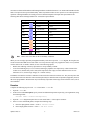
Application Note 137
LabVIEW™ Unit Validation Test Procedure
Introduction
This application note was created for industrial application developers and end-user developers who need a standard
procedure for unit validation of LabVIEW or BridgeVIEW code. This procedure describes a minimum set of
functional testing and documentation to be done before releasing code that must meet certain quality standards.
This procedure does not replace program debugging by the code developer.
The VI undergoing testing is referred to as the unit under test (UUT). Unit testing is necessary before system
integration testing. System integration testing evaluates how your VIs perform with devices and software external to
LabVIEW. This procedure does not provide for system integration testing, which typically is less language-dependent.
However, the output of the unit testing procedure may be useful in performing system integration because it provides
structure information about the LabVIEW application code. Use this procedure as one of many tools, methods, and
activities to help ensure quality software. Exceptions to this procedure may be appropriate for your company culture,
internal procedures, code performance requirements, or other reasons.
Related Documentation
The following documents contain information you might find helpful as you read this document:
•
LabVIEW User Manual
•
G Programming Reference Manual
•
LabVIEW Online Reference, available by selecting Help»Online Reference…
•
Professional G Developers Tools Reference Manual
•
Visual Programming with LabVIEW
Jeff Kodosky and Jack MacCrisken
IEEE Workshop 1991
•
Dataflow Programming with LabVIEW
National Instruments Application Note PN 320117-01
Conventions
monospace
Text in this font is used for the proper names of disk drives, paths, directories, functions,
filenames, and extensions.
monospace italic
Italic text in this font denotes text that is a placeholder for a word or value that you must
supply.
LabVIEW™, ni.com™, and National Instruments™ are trademarks of National Instruments Corporation. Product and company names mentioned herein are
trademarks or trade names of their respective companies.
341761A-01
© Copyright 1999 National Instruments Corporation. All rights reserved.
October 1999
Installation
You can download the software tools for testing from the Example Programs Database on the National Instruments
website at http://www.ni.com/support/epd. Search the database for the string LabVIEW Unit Validation
Test Procedure. These tools are delivered complete with source code and can be copied and modified within your
organization without restriction. You can use them on all LabVIEW supported platforms. Screen resolution of
1024 × 768 or higher is recommended.
Install the VERITOOL directory and its contents to your internal drive or network drive. Complete access rights are
needed for anyone authorized to perform the validation testing. veritool.llb must be accessible during testing with
read and execute privileges, but not write or create.
LabVIEW Language and Protocol
LabVIEW is based on dataflow theory that requires all VI input data be present before execution takes place. The Unit
Validation Test Procedure also is based on this premise, with data inputs to a VI defining the VI test parameters and
data outputs providing execution result of the VI.
LabVIEW also can execute VIs without explicit data inputs to the VI. In these cases, the input data for the VI comes
from sources external to the VI and/or external to LabVIEW. Likewise, a VI may output its data results to an external
sink. VI external sources and sinks are divided into four categories: Global, file, device, and system sinks and sources.
Global Sinks and Sources
Global sinks and sources are external to the VI but internal to LabVIEW, so LabVIEW globals are treated as additional
dataflow I/O to the UUT. Each global data input and output must be identified and included as part of the test procedure
for proper dataflow testing. This category refers only to LabVIEW globals.
File Sinks and Sources
File sinks and sources are external to both the VI and to LabVIEW. You can include file sinks in the test evaluation of
a VI by requiring that the data written to a file also be a defined output (indicator) in the VI code and that the Unit
Validation Test Procedure fails any UUT that does not conform to this requirement. There is no requirement for the file
source data; however, to help diagnose VI functionality, place an indicator on the VI front panel to indicate the data
read from a file.
Devices Sinks and Sources
Device sinks and sources are common with LabVIEW applications interfacing to instruments via software drivers. This
category also includes I/O to devices such as serial ports, parallel ports, memory ports, bus cards, and so on. Device
sinks and sources are external to the VI and to LabVIEW. You can include device sinks in the test evaluation of a VI
by requiring that the data written to a device also be a defined output (indicator) in the VI code, typically a string, and
that the Unit Validation Test Procedure fails any UUT that does not conform to this requirement. There is no
requirement for the device source data; however, to help diagnose VI functionality, place an indicator on the VI front
panel to indicate the data read from a file. This is especially true for devices because confirmation handshaking and
error checking should always be performed when possible.
Application Note 137
2
www.ni.com
System Sinks and Sources
System sinks are calls to the system for data such as date and time or outputs such as DDE strings to applications or
other system controlled events external to LabVIEW. System sinks and sources are external to both the VI and to
LabVIEW. You can include system sinks in the test evaluation of a VI by requiring that the data written to a system
event or object also be a defined output (indicator) in the VI code, typically a string, and the Unit Validation Test
Procedure fails any UUT that does not conform to this requirement. There is no requirement for the system source data;
however, to help diagnose VI functionality, place an indicator on the VI front panel to indicate the data read from a file.
A VI may have any combination of input and output data categories. The test procedure requires identification of these
data categories for each VI to ensure proper testing of the UUT.
Test Procedure
The test procedure provides test files that are separate from the source code VIs, so you can manage the test files
separately from the source code files under test.
Note The test and validation procedure assumes all source code to be validated is complete and debugged.
Test files created by this procedure are VI Test (.VITST) files. Each UUT has a corresponding .VITST test file that
contains the input data values for each test case and all test results. You can save these files as individual files or in
LabVIEW libraries. When you modify and revise a VI, a corresponding new revision of the .VITST test file for the VI
replaces the previous revision. If your internal procedures require archiving previous source code revisions, use the
same archival and storage procedures for the .VITST test files. If you use a LabVIEW library, the operating system
sees all of the test files as one library file, which may cause conflicts if your management procedures are based on
operating system file control because a revision of any .VITST file in the library produces a revision of the library file.
In addition to the .VITST files (one for each VI tested), a VI group file (.VIGRP) is produced to track the unit testing
for an entire group of VIs. This procedure generally considers a group of VIs as a complete VI hierarchy defining an
application. You also can group a set of VIs for use across multiple applications and then run the test procedure to
provide validation release control for each VI in the controlled group.
VITST Test Files
The VITST test file maintains the documented test results and the referenced association to the VI tested. The VITST
test file configuration must be managed in parallel with the VI source code. The test files contain reference to the source
code. The procedure requires that each VITST contain a revision designation of date and time separate from the
associated VI revision information.
Use the VITST tool as a template to create the .VITST file for each UUT (select File»Save As...). Use the .VITST
file to define all test case definitions, test evaluation criteria, test execution data, and test results. Select Operate»Make
Current Values Default then File»Save to store all values and results. You might use one of the following possible
organizational structures:
•
Place the .VITST test files in the same directories or libraries as the source code with like names so that you
maintain tight coupling with the source code files for configuration management and archival procedures.
•
Place the .VITST test files in mirrored but separate directories (or libraries) from the source code so that you
maintain separate file configuration management for source and test files, but rely on manual or other system
association between the source and test files.
© National Instruments Corporation
3
Application Note 137
VIGRP Group Tracking File
You use the .VIGRP file to define all VIs in the test group and help establish the test order and record the test results
for each UUT. This file maintains the association of VIs tested as a group. This group normally consists of the entire
LabVIEW application that is tested. It also might be a group of reusable VIs that are released and controlled for use
across multiple LabVIEW applications. The VIGRP file also is used to store the summary of test results for the group.
The VIGRP tool exports the data into a standard tab-delimited ASCII file. The VIGRP file can be used to link the unit
validation testing described in this procedure and the system integration testing described by your internal procedures.
Application Design and Specification
The structure produces a number label for each VI that identifies its position in the application hierarchy. This number
is not required for the unit test procedure but provides a manual reference link to the application design specification.
It may be used to provide reference linking from the design specification to the code documentation to the unit
validation test to the system integration test.
Source Code Availability
All tested source code is subject to visual inspection and execution, so read and execute privileges are required. Each
source code VI tested is referenced and called from a LabVIEW test VI (VIT). The disk storage required for the VITST
file is relatively small and is a function of the data sizes for the defined test cases. The VITST file places the VI UUT
in its diagram for reference and execution. The VITST references the VIs by name, so all VIs in a test group must have
unique names. You must revalidate your source code whenever you make revisions following validation testing.
Procedure Application
The procedure implements the following steps:
1.
Code Identification – Identifies all VIs associated with the application or grouping to be validated and forms a
master list of VIs.
2.
Test Case Definition – Specifies the input data and evaluation criteria for each data execution test case, including
data from external sources such as files, globals, and system calls.
3.
Inspection Test – Examines the VI UUT for specific attributes, features, and definitions to verify that it contains
the necessary attributes and documented data.
4.
Code Execution Test – Executes each test case and performs manual evaluation of the output results against the
established criteria for the VI UUT.
5.
Test Documentation – Provides configuration management information for the test run and information
concerning each VI unit test.
Code Identification
This step locates and documents the VIs to be validated for the test group. This may be an entire application as defined
by your organization. It also may be one or more libraries of reusable shared VIs that need validation before release.
Prepare the identification information during code design and development to save time and use the information to
fulfill the requirement for this step.
Because the VI testing order is based on position in the application hierarchy, the hierarchy structure must be
determined before test execution. The lowest level VIs should be validated first, moving up the hierarchy one level at
a time. This process captures and identifies failures with the highest accuracy and on the broadest basis relative to the
application.
Application Note 137
4
www.ni.com
Because testing must proceed bottom-up for the group hierarchy, list the VIs in the .VIGRP according to the VI
number, from highest to lowest. You then can use the .VIGRP master list to determine the testing order.
Note LabVIEW functions and VIs undergo testing before release and are considered validated for the
purposes of this procedure. However, you can use the test procedure to validate these VIs and functions if
needed.
If the VI hierarchy was not provided as part of the code design information, select Project»Show VI Hierarchy to
display the hierarchy for a VI.
Procedure
1.
Open VIGROUP.VIGRP, and save a copy with a unique name for your application or group by selecting
File»Save As…. In your VIGRP file, record the following information for each VI in the grouping.
•
VI Name – List the VI file name, complete with any extension. The name must be unique in the grouping.
•
VI # (Not Required) – List the number assigned to the VI. This number is established during design and
development and relates to the position of the VI in the hierarchy.
•
VI Revision – List the revision number of the VI as defined by your organization. Select Windows»Show VI
Info… to view the current revision number.
•
Test File Name – Enter the .VITST test filename as the files are created.
•
Test Results Summary – Enter pass or fail for each test performed. Leave untested fields blank.
2.
Store your entries to disk by selecting Operate»Make Current Values Default then selecting File»Save.
3.
Open the VI.VITST tool and save it as VIname.VITST by selecting File»Save A Copy As…. Create one .VITST
file for each VI identified, even if the VI has multiple calls listed. The names should match those in the .VIGRP
listing.
Test Case Definition
The Test Case Definition step specifies the input data and evaluation criteria for each data execution test case, including
data from external sources such as files, globals, and system calls. The number of test cases used varies for each VI
and is dependent on its function. Determine the number of test cases and the data inputs with the developer to cover
the functionality of the VI, including all boundary conditions.
Data Test
You must define the input specification and the evaluation criteria for each VI UUT before you perform the test. This
includes data from devices, globals, files, and system calls. Each definition is a test vector, because all data input values
are defined for each. Test vectors should be determined for a VI based on its function, boundary conditions, internal
coding, and range. The number of test vectors varies for each VI. You use the .VITST file for each VI to establish the
complete array of test cases, their associated input states, their associated evaluation criteria, and the output results.
The input data of the VI is its domain and output data is its range.
Note Choose test vectors that exercise all independent data paths in the code and that produce the
complete VI range.
© National Instruments Corporation
5
Application Note 137
You must test functional boundaries and limiting boundaries within the domain of a VI. Functional boundaries define
limits of an input for the expected functionality. Values beyond these limits are not expected to occur during normal
operation. Limiting boundaries are usually precision-related and depend on the input data representation. The
following table shows limiting boundaries for various data representations.
Representation
Minimum
Maximum
I8
–128
127
I16
–32768
32767
I32
–2147483648
2147483647
U8
0
255
U16
0
65535
U32
0
4294967295
SGL
–3.4E38
3.4E38
DBL
–1.7E308
1.7E308
EXT
–1.1E4932
1.1E4932 (platform dependent)
String
empty
Array
empty
Note Choose test vectors that test the VI boundary conditions.
When you wire an empty input array through the boundary of the For Loop in the .VITST diagram, the loop does not
execute because LabVIEW does not auto-index a For Loop when an empty array supplies the index, even if you hard
wire the index to the N variable. Instead, use one of the following options:
•
Disable auto-indexing of the array input at the For Loop boundary terminal.
•
To see the initializing array as a set of values (assuming it populates some output array or data element of the
VITST UUT), load the array with a value(s) that represents some empty or initial condition for the VI UUT
function it serves, such as empty string(s) or 0 numeric value(s).
In addition, User Interface VIs have a definition of cause and effect actions for each test case. They also may have data
I/O concurrent with cause and effect. The cause description may be defined in terms of input data (supplied by the user)
that is non-programmatic. Result criteria may be defined by output data values/ranges and/or interface effect, such as
color attributes.
Procedure
Complete the following steps for each .VITST listed in the .VIGRP file.
1.
Open the .VITST file.
2.
In the text box under Description, specify criteria for additional inspections required by your organization, using
the following format:
Criteria Other: Criteria Description(s)
3.
Open the .VITST diagram and place the VI UUT inside frame 2 of the sequence structure.
4.
If the UUT uses LabVIEW globals, complete the following steps:
a.
Place the input globals in frame 1 of the VI UUT Test Socket.
b.
Place output globals in frame 3 of the VI UUT Test Socket.
Application Note 137
6
www.ni.com
5.
Open the Show Help window for the VI UUT. Use this information to help establish the data inputs and outputs
for the VI. Create one array on the .VITST panel for each VI UUT input and output (use the same names for
reference). Open the UUT panel and copy each UUT input and output to the .VITST arrays to establish their types.
Perform this process for any globals inputs and outputs used by copying from the global(s) front panels.
If the control or indicator is an array, create a cluster array type in your .VITST before copying because you cannot
create arrays of arrays in LabVIEW. Set the cluster to autosizing by selecting Autosizing from the pop-up menu
to automatically size the cluster to the array size for easy viewing and manipulation.
After you copy an input or output to the .VITST, check the menu to see if it is a Type Definition. If so, select
Disconnect from Type Def so that type definition modifications do not change your .VITST file.
© National Instruments Corporation
7
Application Note 137
6.
Wire the input and output arrays across the Sequence structure boundary to the UUT inputs and outputs in frame 2
and to the associated globals in frames 1 and 3. This produces an executable .VITST for testing the UUT.
If the input or output in the UUT is an array, unbundle it from the .VITST cluster array for wiring to the UUT.
7.
To view the test results for previous executions or the data inputs for current executions, create attribute nodes for
all input and output arrays and wire the index to each attribute node in sequence frame 4.
Application Note 137
8
www.ni.com
Note Execution results are displayed for all cases only after all cases execute.
8.
Enter the test values for all data input test vectors. Each array element represents a different test case (vector) and
the execution order follows the array order starting with 0.
9.
If the VI UUT makes device calls, file I/O calls, or system calls, enter the descriptions of the calls that must be set
before execution of the test vector in the text box under the Test Case Description label using the following format:
Devices:
Name: device name
State: condition or state description
Files:
Name: filename
State: condition or state description
System:
Name: system call (or program) name
State: condition or state description
These states must be available or editable at test execution.
Files may represent specific test files that have been created for test purposes, or you can describe the exact file
content, which can be visually checked or created before test execution.
10. Enter the evaluation criteria for each test case in the following fields:
•
Output Data Criteria – Enter the output data criteria, including globals, using the following format
Data Output Name: Criteria
Describe the data criteria using the following syntax guideline:
numeric
min value<>max value (inclusive); another range
string
value 1, value 2,…
Boolean
true or false
array
value or range 0, value or range 1,…
(only one listed assigns to all elements)
•
External Event Criteria – Enter external event criteria, which may include manual checks for external device
states, files, and system or program states. Use the following format:
Event Name:Criteria
•
User Action Criteria – Enter the user interface criteria using the following format:
Cause: Cause Description
Effect: Effect Description
11. Save your test specification values and entries by selecting Operate»Make Current Values Default and then
selecting File» Save.
Inspection Test
The Inspection Test involves examination of the VI UUT for specific attributes, features, and definitions to verify that
it contains the necessary attributes and documented data. These items provide for minimum levels of proper code
definition, documentation, and specification. The attributes range from proper documentation to specific data
concerning VI calls to external items such as globals, files, and devices. All listed attributes and definitions must be
present to pass the Inspection Test.
© National Instruments Corporation
9
Application Note 137
The purpose of the documentation entries in the VI Description dialog box is to specify the externals of the VI. The
basis of testing is the data I/O of a VI, so testing can be valid only if all data I/O is included. In LabVIEW most data
I/O is evident on the front panel of a VI, but some is blind I/O. This procedure requires explicit specification of blind
I/O and, in cases of external data outputs such as device, system, and file output, requires the I/O to be sighted, or
supplying wired panel indicators of the data output.
Note Occurrences are not recommended for use in code that must be validated. However, if use is
essential, they must be documented as described in the VI Description dialog box to provide a reference
for testing at the system integration level.
Procedure
For each VI listed in the .VIGRP file, complete the following steps.
1.
Open the .VITST file for the UUT and open the VI UUT panel from the .VITST diagram. Select Windows»Show
VI Info… and look for the following information in the Description text box. The information must be listed in
the specified order.
a.
VI Revision – Lists the latest revision designation of the VI and must be the first line in the Description text
box. Use the following format:
Revision: <month/day/year>
You may substitute your internal revision standards for <>.
b.
Description – Includes an explanation of the purpose and functionality of the VI. The description must use
the following format:
Description: description text
c.
Globals – Lists the VI global call specifications. Use the following format:
Globals:
Name: global name
Inputs: global element name, global element name, …
Outputs: global element name, global element name, …
The global specification content must include the name of the global(s), followed by the name of the global
element(s) used as inputs, followed by the name of the global element(s) used as outputs. If no globals are
named, enter none in the globals specification.
d.
Occurrences – Includes the name of the occurence(s) followed by the name of the Boolean indicator used to
output the occurrence wait state. There must be one indicator name for each occurrence name. Use the
following format:
Occurrences:
Name: occurrence name
Indicator: occurrence output indicator name
If no occurrences are named, enter none in the occurrences specification.
e.
Devices – Includes the name of the device(s), communication description, and the name of the indicator used
for the output of the device call data. There must be one indictor name for each device name. Use the
following format:
Devices:
Name: device name
Comm: communication description
Indicator: device output indicator name
If no devices are named, enter none in the devices specification.
Application Note 137
10
www.ni.com
f.
Files – Includes the reference name of the file(s), followed by the name of the indictor used to output the file
write data. The reference name does not have to correspond to the disk filename. Use the following format:
Files:
Name: file reference name
Indicator: device output indicator name
If no files are named, enter none in the files specification.
g.
System Calls – Includes the reference name of the system call(s) and the name of the indicator used to output
the system call data. Use the following format:
System:
Name: system call reference name
Indicator: system call output indicator name
If no system calls are named, enter none in the system specification.
2.
Open the VI UUT front panel and block diagram for code inspection. In addition to any criteria required by your
internal procedures, look for the following items on the block diagram:
•
Structures – All code structures must include a description in the Description dialog box. You can access the
Description dialog box by selecting Description from the pop-up menu of the structure.
•
Diagram Code and Style – The diagram code wiring and layout must be uniform, readable, and maintain a
left to right dataflow organization. Each global listed in the previous step must exist in the block diagram code
and have the same name as listed in the VI Information dialog box.
•
VI Calls – All VI calls, including multiple calls to the same VI, must include a description in the Description
dialog box that explains the purpose and function of the structure. You can access the Description dialog box
by selecting Description from the pop-up menu of the structure.
3.
On the front panel, look for the VI I/O and style. The VI I/O on the front panel must be readable and maintain a
general left side inputs, right side outputs organization. Each terminal on the block diagram must have a visible
control or indicator on the front panel. Each device indicator, file indicator, and system call indicator named in the
VI Information dialog box must exist visibly on the front panel and must have an associated connection on the
block diagram.
4.
Record the inspection test evaluation results for each item in the Inspection Test section of your .VITST. Include
any comments that may help resolve failures in the Description field. Use the buttons to the right of the Description
text box to indicate Pass or Fail for each item inspected on the .VITST front panel.
5.
Save your test results by selecting Operate»Make Current Values Default, and then select File»Save.
Code Execution Test
The Code Execution Test executes each test case and performs manual evaluation of the output results against the
established criteria for the VI UUT. The Code Execution test validates that the VI UUT executes properly for the set
of defined test cases. Automated evaluation against the test criteria currently is not provided.
Perform the required external check items before execution. This part of the process allows this procedure to integrate
smoothly with system integration testing that may reference results from this procedure.
Procedure
For each VI listed in the .VIGRP file, complete the following steps:
1.
Open the .VITST file for the VI UUT. With all test cases and evaluation criteria defined in previous steps, run the
.VITST and click the Execute Test button. The Run Next Case button appears along with a dialog box displaying
the case number you are about to execute.
2.
Review the Test Case Description text box of the case to be executed for any operations that must be performed
on external items such as system objects, files, and devices before execution of the test case. Perform the actions
required for the test case to execute, and click the Run Next Case button to execute the VI UUT test case.
© National Instruments Corporation
11
Application Note 137
3.
If the UUT is a user interface VI, review the User Action Criteria text box for interface actions to be tested. Then,
open the VI and execute the user actions directly on the VI UUT.
4.
Evaluate the test results against the defined criteria for the test case, including Output Data Criteria, External Event
Criteria, and User Action Criteria. Indicate Pass or Fail for the test results. If no criteria is listed, indicate a Pass
result.
5.
Enter any evaluation result comments into the Test Case Description for the appropriate case using the following
format:
Criteria 1: criteria evaluation description
Criteria 2: criteria evaluation description
…
If your internal procedures allow mixture of evaluation comments and descriptions, enter evaluation descriptions
into the criteria fields.
6.
Save your test and evaluation results by selecting Operate»Make Current Values Default and then selecting
File»Save.
Test Documentation
The Test Documentation step provides configuration management information for the test run and information
concerning each VI unit test. It also documents the summary of results for the entire group.
You can save the test results, including all cases tested and the inspection test results, directly if your internal
procedures allow for LabVIEW binary test files. If your procedures require other forms of storage such as database
formatting, you can enter the results manually into a table and export the data to a tab-delimited ASCII file.
The test documentation allows for multiple versions of the .VITST file. However, there is only one active .VITST
allowed at a time because modifications occur within the file. If your internal procedures require you to maintain
previous versions of the .VITST file, archive them for recovery when needed.
Note The .VIGRP file can provide a good mechanism for integrating the test results with system
integration testing.
Procedure
1.
In the .VITST, enter the Tester ID and VI Revision information. Use the .VITST revision specification required
by your internal procedures in the VI Description dialog box. In addition, enter any information that may help
correct failures or other general comments that must be documented as part of the test. Enter this information
immediately after the Revision specification. To store the entered information permanently, select Operate»Make
Current Values Default then select File»Save.
2.
Open the .VIGRP front panel for the group being tested. Enter the test result summary information (Pass/Fail)
for the VI UUT in the Inspection Test Result, Data Tests Result, External Test Result, and User Interface
Test Result fields. Enter any Revision specification required by your internal procedures to the first line of the
VI Description dialog box. To store the entries permanently in the .VIGRP file, select Operate»Make Current
Values Default then select File»Save. To export the .VIGRP results, run the .VIGRP and click the Save to
Spreadsheet File button to export the data to a tab-delimited ASCII file.