1
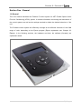
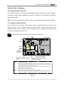
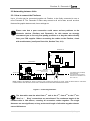
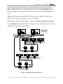
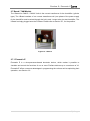
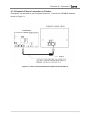
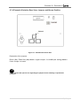
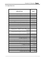
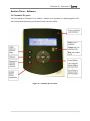
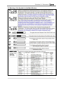
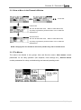
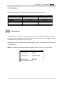
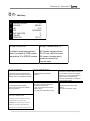
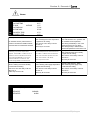
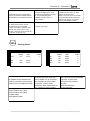
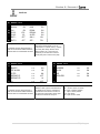
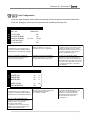
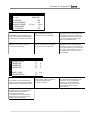
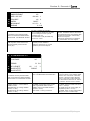
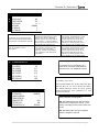
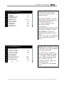
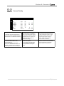
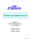
FLEXMATIC E USER GUIDE VERSION 2.0 JULY 2015 AET Manufacturing Ltd, Unit 2707, The Center, 99 Queen’s Road Central, Hong Kong UK office +44 (0)1342 310400 / Hong Kong office +852 2575 218 / [email protected] flexiblespace.com Flexface E / Flexmatic E 2015 Table of Contents Section One - General ............................................................................................... 2 1.0 General .......................................................................................... 2 Section Two - Hardware............................................................................................ 3 2.0 Flexface Evolution 24V AC ................................................................. 3 2.1 Flexface Evolution 24V AC ................................................................. 3 2.2 Networking between Units.................................................................. 4 2.3 Eprom / Flash memory ...................................................................... 6 2.4 Humitemp and Humitemp Evolution ..................................................... 7 2.5 PTC Temperature Sensor .................................................................. 8 2.6 PTC Airflow Sensor / Differential pressure switch ................................... 8 2.7 Board / TAM Module ......................................................................... 9 2.8 Power Supply Module for Flexmatic E ................................................ 13 2.9 Flexbus Cables and other Connection Cables ...................................... 15 2.10 Hardware, Technical Specification ................................................... 17 2.11 Spare Parts List ........................................................................... 18 Section Three - Software ........................................................................................ 19 3.0 Flexmatic E Layout ......................................................................... 19 3.1 Meaning of the Symbols in the Main Window ....................................... 20 3.2 Flexmatic Parameter List ................................................................. 42 3.3 Messages / Warnings / Alarms .......................................................... 48 Section Four - Connections ................................................................................... 50 4.0 Connection Guide ............................................................................. 50 1|Page Flexface E / Flexmatic E 2015 Section One - General 1.0 General This user manual describes the Flexface E control system for AET Flexible Space Under Floor Air Conditioning (UFAC) system. It contains information concerning the architecture of the control systems as well as the settings required to obtain the desired behaviour of the unit. The Flexface control system will effectively manage all the different functions of the CAM range of units, depending on the Eprom program (Eprom explanation see: Chapter 2.3 Eprom). In the following sections, the hardware and later, the software (firmware) are explained in detail. 2|Page Flexface E / Flexmatic E 2015 Section Two - Hardware 2.0 Flexface Evolution 24V AC The Flexface Evolution is a microprocessor-based electronic card, which is able to manage the devices and the sensors installed in the CAM. The Flexface E is installed in the electrical panel of each CAM. NB: To access / set timer & some other functions, a visual display Flexmatic E is required. 2.1 Flexface Evolution 24V AC As the Flexface E is the “Heart” of the System which controls all functions of the unit, some jumpers have to be set in order to tailor the control board. Most of these jumpers are already correctly set in the factory; only the jumper for the unit’s address (“A”) has to be set in the field, during start-up of the unit. Never add / remove jumpers when Flexface is under power A EWE FLEXFACE E AI + E/F Backup battery EPROM SG HM quick plug-in connector to "local" LCD display. ES I-Board RS485 for Communication to Flexlink. quick plug-in connector to connect additional Room-sensors and/or TUx. FLEXBUS quick plug-in connector to Flexmatic E or next/previous Flexface. FLEXBUS quick plug-in connector to next/previous Flexface. JUMPERS: EWE: EPROM write enable. Always set this jumper. A: Address setting. See chapter “Networking” for Details. Units, not connected to others: NO Jumper. AI: Analogue Inputs selection. Set indicated jumper only if “PTC Airflow” is used. Do not set any jumper E/F: if differential pressure sensor is used for airflow detection. EPROM / Flash memory selection jumper. Set the jumper when EPROM is installed. Do not set this SG: HM: ES: jumper when Flash memory is installed. Subgroup ID setting. Do not set these Jumpers. Comb connector for I-Module (present when humidifier is installed). EPROM /Flash memory size selection jumper. Set jumper between middle and right pins for 1 or 2 Mbit size memory devices. Set jumper between middle and left pins for 4 Mbit size memory devices. Figure 1 3|Page Flexface E / Flexmatic E 2015 2.2 Networking between Units 2.2.1 How to connect the Flexfaces Up to 16 units may be connected together via Flexbus, to be finally connected to one or more Flexmatic E. The Flexmatic E offers easy access to all unit’s data, as well as other features like graphic data records, timer settings etc. Please note that a poor connection could cause serious problems to the electronic devices (Flexface and Flexmatic); for this reason we strongly recommend you to use only first quality products or to buy the cables directly from your FSS supplier. Before connecting the cables to the Flexface, check with a cable-tester, (see Spare Parts List, Section Two, 2.11). EPROM FLEXFACE E TO NEXT FLEXFACE EPROM FLEXFACE E FLEXBUS: 6 wires flat screened cable, 8 pole connector TO FLEXMATIC E (if installed) 8 wires flat cable. The cable must be screened if Flexmatic is not installed on the door of the unit. NOTE: CONNECT THE SCREEN OF THE FLAT CABLE TO THE CLOSEST "PE" (EARTH) OF THE EL. PANEL ON BOTH ENDS OF THE CABLE. FLEXBUS CABLES MUST BE INSTALLED SUITABLY SEGREGATED FROM POWER TRANSMISSION CABLES. Figure 2 - connecting Flexfaces. The bus-cable must be wired from 1st unit to the 2nd, from 2nd to the 3rd etc. “Star” or “ Ring” connections are not allowed. The maximum length of the Flexbus-cable is 300 metres, counting all connection cables together. The single distances are not significant, as long as the total length of all cables together doesn’t exceed 300 metres. 4|Page Flexface E / Flexmatic E 2015 2.2.2 Typical network with Flexfaces, Terminal Units and external sensors Note: Length of Flexbus, connecting the Flexfaces, must not exceed 300 metres in total. Length of Flexbus, connecting the Sensors and the TUx, must not exceed 300 metres in total. Note: Sensors must be connected first to the Flexface (max. distance 25 metres to the Flexface), with TUx “after” the sensors, using “T” connectors. All Bus-cables, going out from the CAM-C / CAM-V unit must be screened and earthed. In total 24 Master TUx are addressable. Including Slave TUx, the number must not exceed 32 TUx in total, connected to one Flexface. Unit 1 (A) Unit 2 (B) 6 wires To next Unit 8 wires 6 wires Master xTU B1/0 Slave xTU B1/1 Master xTU B2/0 22,5 22,5 22,5 8 wires 6 or 8 wires 6 or 8 wires To next xTU Additional Room Sensor A1 Additional Room Sensor A2 T-connector B1 T-connector B2 6 or 8 wires 8 wires 6 or 8 wires Master xTU A1/0 Slave xTU A1/1 Master xTU A2/0 22,5 22,5 22,5 6 or 8 wires 6 or 8 wires Additional Room Sensor A2 T-connector A1 T-connector A2 max. 3m Additional Room Sensor A1 6 or 8 wires To next xTU Up to the last sensor: max. Hirobus length: 25 m Figure 3 - Network with Flexfaces and TUx 5|Page Flexface E / Flexmatic E 2015 2.3 Eprom / Flash memory The Eprom / flash is the device which stores the program the Flexface or Flexmatic E that has to work with. It doesn’t store any user-settings - this is done by the device itself (in the RAM and the Eprom). The version name and the number are printed on the Eprom / flash label. The following Eproms / flashes are currently used for AET Flexible Space units (the xxx is a placeholder for the actual version): HVM Eprom........................................................................ Bit 1.00.xxx.......................................................................For Flexface E 24V AC HVE 1.00.xxx Flash, 4 MBit, For Flexmatic E. Figure 4 – Eprom (top) and Eprom Remover Tool Power-off the device before mounting/dismounting the Eprom. Remove Eprom only with a special tool; never use a screwdriver. For correct installation direction, please refer to section 2.1 and Section 2.7.2 Flexmatic connection. 6|Page Flexface E / Flexmatic E 2015 2.4 Humitemp and Humitemp Evolution The Humitemp is a combined Temperature / Humidity Sensor. If connected, the Flexface will use the values of the Humitemp for control according the sensor priority settings. It is connected to the Flexface through Flexbus-Cable (max. length: 25 m). 2 sensors can be connected to one Flexface (= to one air handling unit). Humitemp, Humitemp E Front View Temperature Reading Humitemp open, Rear View Humidity Reading Flexbus Address Switch Humitemp Evolution open, Rear View Flexbus Address Jumpers Figure 5 – Humitemp The Address-Switches / jumpers inside the Humitemp allow the following setting; Sensor 1 Sensor 2 Figure 6 – Address switches / jumpers 7|Page Flexface E / Flexmatic E 2015 2.5 PTC Temperature Sensor The PTC Sensors are used to read return air and supply air temperatures as well as outdoor temperature. There are different types available: please refer to Spare Parts List, Section Two, 2.11. PTC Sensors are temperature-sensors, changing the resistance according to the temperature (positive temperature coefficient). The connection is 2 poles. The max cable length is 10 metres. Measuring Element Cable Figure 7 – PTC Sensor 2.6 PTC Airflow Sensor / Differential pressure switch The PTC Airflow Sensor measures airspeed in the same way as the one used for Anemometers. There is an automated setup-procedure in the software to assist in setting-up. The PTC Airflow is supplied with 24V, and gives back a signal of 0-10V DC, according the airspeed measured. It must be connected to an analogue input. The connection is 3 poles. The length of the cable for the sensor is 2 metres. The adjustment is done by software. Note: depending on the unit’s configuration, a differential pressure switch could be an alternative. It would need mechanical adjustment. Measuring and Heating Element Cable Figure 8 – PTC Airflow Figure 9 – Differential pressure switch 8|Page Flexface E / Flexmatic E 2015 2.7 Board / TAM Module The I-Board for CAM-C / CAM-V Units is the current transformer for the humidifier (cylinder type). The I-Board consists of one current transformer-coil (one phase of the power supply for the humidifier must be wired through the hole); and 1 output relay (to start humidifier, The I-Board is simply plugged onto the Flexface. Please refer to Section 2.1, for the position. Figure 10 - I-Board 2.7.1 Flexmatic E Flexmatic E is a microprocessor-based electronic device, which makes it possible to visualise and control the functions of one or more Flexface devices up to a maximum of 16. Flexmatic E offers numerous advantages in programming the units as well as optimising their operation; see Section 3.0. 9|Page Flexface E / Flexmatic E 2015 2.7.2 Flexmatic E direct Connection to Flexface Flexmatic E can be fixed on the front panel of the unit. Connect the FLEXBUS cable as shown in Figure 11. Figure 11 - Direct connection between Flexface and Flexmatic E 10 | P a g e Flexface E / Flexmatic E 2015 2.7.3 How to connect more than one Flexmatic to the network More than one Flexmatic E may be connected to a network. All Flexmatics will show the same values (as they are reading out the data from the Flexfaces), changes of parameters can be set from any Flexmatic – the last set of information sent to the Flexfaces through a Flexmatic is valid. The only limitation (despite of the total Flexbus cable length of max. 300 metres) is the power supply of the Flexmatics: 1 Flexface can supply 1 only Flexmatic E. If more Flexmatics are connected, PSM modules (see page 13, 2.8.1) Figure 12 - Example how to connect two Flexmatic Es to the network 11 | P a g e Flexface E / Flexmatic E 2015 2.7.4 Flexmatic Evolution Rear View, Jumpers and Eprom Position Figure 13 - Flexmatic Evolution Rear Description of the jumpers: Eprom (2M) / Flash Size (4M): Middle + Upper Jumper: 2 or 4 MBit (std. setting) Middle + Lower Jumper: not used. Please take special care regarding the jumpers when installing a replacement Flexmatic. 12 | P a g e Flexface E / Flexmatic E 2015 2.8 Power Supply Module for Flexmatic E 2.8.1 PSM Hardware Flexmatic E may be supplied mounted in an independent electrical panel containing a power supply module as well (PSM Power Supply Module) if the distance to the next Flexface is more than 10 metres. The PSM Module itself needs a power of 24V AC / 30 VA. Input 24VAC / 24VDC+ 24VAC / DC GND not used Output Do not use Fuse 8x20mm, 250V, T1.6A from Flexface to Flexmatic Figure 14 - PSM Module 13 | P a g e Flexface E / Flexmatic E 2015 2.8.2 PSM Connection The connection between Flexmatic E and the PSM is carried out in the factory by means of an eight wire Flexbus cable. The PSM should be connected to Flexface through a six wire, screened Flexbus cable; the screen needs to be earthed in both terminals. When the system consists of more than one CAM unit, a Flexmatic can be connected to any unit where Flexface has a free Flexbus connector (usually either the first or the last one of the Flexface chain). Figure 15 - Connection of Flexface LAN to Flexmatic E with PSM. 14 | P a g e Flexface E / Flexmatic E 2015 2.9 Flexbus Cables and other Connection Cables The connections between various Flexfaces, Flexmatic display and sensors are carried out with cables having a different number of wires and different connectors. To see how these cables have to be configured, see below. For the type of cable and connectors refer to the Spare Parts List included in this manual. Please note that a poor connection could cause serious problems to the electronic devices (Flexface and Flexmatic); for this reason we strongly recommend you to use only first quality products or to buy the cables directly from your AET Flexible Space supplier. Before connecting the cables to the Flexface, check with a cable-tester (see Spare Parts List, Section 2.11) EIGHT POLES MODULAR JACK EIGHT WIRES FLAT CABLE. USE SCREENED CABLE WHEN CABLE IS RUNNING OUTSIDE THE UNIT. Figure 16 - Eight-wire; eight pole connector Flexbus cable for Flexmatic, Humitemp and TUx connections EIGHT POLES MODULAR JACK (USE ONLY THE CENTRAL SIX POLES) SIX WIRES FLAT CABLE. USE SCREENED CABLE WHEN CABLE IS RUNNING OUTSIDE THE UNIT. Figure 17 - Six-wire (Pin 1 and 8 not connected) Flexbus cable, for Flexface to Flexface connections, eight pole connectors. This cable must be screened FOUR POLES MODULAR JACK FOUR WIRES FLAT CABLE Figure 18 - Four wire flat cable for local LCD Display, four pole connectors 15 | P a g e Flexface E / Flexmatic E 2015 2.9.1 Addressing When Flexfaces are connected by Flexbus cables, it is necessary to assign a different address to each of them by means of a group of jumpers on the Flexface. The jumper position is described in The units must be addressed consecutively, starting from #1. The bus-cable doesn’t necessarily need to go in order of the addresses; it could also be wired 1-5-4-2-3, for example. #1 #5 #9 #13 #2 #6 #10 #14 #3 #7 #11 #15 #4 #8 #12 #16 Figure 19 - Address jumpers 16 | P a g e Flexface E / Flexmatic E 2015 2.10 Hardware, Technical Specification Flexface E 24V AC Power Supply Digital Out (Triac) Digital Out (Relay) Analogue Out (0-10V) Analogue In (resistive) Analogue In (resistive / 0-10VDC) Storage Temperature Operating Temperature Range 24VAC, 10%; 50 Hz 7 2 (max. 24V – 1A) 2 8 3 -10 (not condensing) to +65°C 0 (not condensing) to +55°C Humitemp Power Supply Temperature range Humidity range Minimum airspeed required Temperature precision Humidity precision (@25°C) 10VDC (from Flexbus) 0 to 50°C 20 to 90% 0,5 m/s 0,5°C 40 to 65%: 2 %r.H. 20 to 90%: 4 %r.H. PTC Temperature sensor Cable length Temperature range Point of calibration 10m -28 to 100°C 2000 at 25.0°C Flexmatic E Power Supply Graphic Display Mounting hole Power Supply Module (PSM) Power supply Output I-Board (Current transformer) Current Range Digital Out (Relay) 10VDC (from Flexbus) Backlit, 200 x 64 pixels 175 x 150mm 24VAC, 10%; 24VDC, 20% 10VDC (Flexbus, stabilised); 24VAC, 10%; 24VDC, 20% (filtered) 0 – 30A 1 (max. 24V – 1A) 17 | P a g e Flexface E / Flexmatic E 2015 2.11 Spare Parts List DESCRIPTION CODE Flexface E user manual FSS 021 076 Flexface E (Evolution) 24 AC board 275 29701 I-Board / TAM Module 275 099 Alarm Board 24VAC 275 148 Heaters Board 275 366 Probe PTC 2 kohm L = 10 m (outdoor temperature) 275 155 Probe PTC 2 kohm L = 10 m (supply temperature) 275 262 Probe PTC 2 kohm L = 10 m (return temperature) 275 263 Probe Temp. + Hum. Humitemp 275 181 Probe airflow PTC 275 184 EPROM Flexface HVM 100*** 275 877 FLASH Flexmatic HVE L1 100*** (Language Pack 1: English, German, Italian, Polish, Spanish) FLASH Flexmatic HVE L2 100*** (Language Pack 2: English, Portuguese, Swedish, French)) Flexmatic Evolution Classic 275 876 275 69102 Kit Liquistat 482 979 LWD (Leakage Water Detector) 275 353 Flat cable 8 way M-M L = 1 m 275 607 Flat cable 8 way M-M L = 10 m 275 610 Flat cable 6 way screened (specify length) 275 625 Flat cable 8 way screened (specify length) 275 626 Module PSM 24/24-10 for Flexmatic 275 316 "T" adapter for Flexbus 275 652 Spacer Set for Flexface Board 4# 035 107 Digital Expansion Board 275 365 Flexbus / Flexnet Cable Tester 480 061 Flexbus / Flexnet Interface Tester 480 060 Flexmatic cable with Ferrite XXXX 276 230 18 | P a g e Flexface E / Flexmatic E 2015 Section Three - Software 3.0 Flexmatic E Layout The front panel of Flexmatic E for CAM-C / CAM-V units consists of a backlit graphic LCD, with eight push buttons that permit input function and two LEDs. Figure 20 - Flexmatic E Front View 19 | P a g e Flexface E / Flexmatic E 2015 3.1 Meaning of the Symbols in the Main Window 20 | P a g e Flexface E / Flexmatic E 2015 3.1.2 How to Move in the Flexmatic Window to next unit User menus: to select the menu, “Enter“ to enter the menus, (2 sec) to go back to previous screen or to un-mark the selected icon. Service menus: to select the menu, “Enter“ to enter the menus, (2 sec) to go back to previous screen or to un-mark the selected icon. NOTE: changing from one window to the next is possible only with un-marked icons. 3.1.3 The Menus The menus are divided in two groups: User and Service menus. User menus contain parameters for the daily operation (like setpoints, timer settings etc.); Service menus contain parameters for setup, troubleshooting and manual operating mode. 21 | P a g e Flexface E / Flexmatic E 2015 3.1.4 User Menus This window contains the following menus (from top left to bottom right). STATUS REPORT GRAPHIC DATA RECORD HM (FLEXMATIC) SETUP UNIT SETUP WARNINGS / ALARMS WORKING HOURS TIMER SETTINGS Readable w/o Password YES YES YES YES YES YES YES Write Access Level read only (LEVEL 0) (LEVEL 1) (LEVEL 1) (LEVEL 1) (LEVEL 1) (LEVEL 1) Status Report The status report contains the last 200 events (for each individual unit), which occurred to the unit, in order of appearance. Each unit contains its own collection of 66 pages. Use and button to move from one unit to the next. Left () from unit no. 1 there is the so called “System report”, a summary of all events of all connected units. NOTE: The status report can be entered by pressing “Enter” from a unit’s main screen. STATUS REPORT PAGE 66 21.02.2001 20:10 RESET 21.02.2001 20:10 UNIT1 ACKNOWLEDGE 20.02.2001 16:45 WARNING HIGH ZONE TEMPERATURE 22 | P a g e Flexface E / Flexmatic E 2015 Graphic Data Records For each single unit, an 8-day graphic data record as well as a 24-hour record for return air temperature, supply air temperature and return humidity is available. The temperature/humidity scale can be adjusted (Enter- UP/DOWN). The records are stored after power off. 23 | P a g e Flexface E / Flexmatic E 2015 HM Setup 000 001 002 003 004 005 006 007 Flexmatic Set-up 1 of 1 PASSWORD (LEVEL0) LANGUAGE : TIME : DATE : TEMP. INDICATION CONTRAST : BUZZER FRQ: 001 Help: PASSWORD ???? ENGLISH 22:12 TH 22/06/2002 °C 74 OFF / 0.6 002 Help: Flexmatic Set-up 1 of 1 for read/write access password level 1 002: Flexmatic language selection needs to be entered for USER windows, 003, 004: time / date to be entered. password level 5 for SERVICE windows. 006: Increase / decrease value to optimise the contrast of the Flexmatic display 001 Help: PASSWORD 003 Help: ZONE SETPOINT for read/write access password level 1 needs to be entered for USER windows, password level 5 for SERVICE windows. Setpoint valid during automatic operation. 005 Help: HUMIDITY SETPOINT 006 Help: AUTORESTART After power on the unit will start its fan after the selected time (+ app. 20 seconds time the control needs to boot). 2 min. later the control starts to work. For units equipped with humidity control. To be set to NO if no humidity control is requested. 004 Help: TUx SETp.RANGE The maximum allowed difference between the TUx setpoint and the zone setpoint set in line 112. If TUx setpoint was set higher / lower than allowed, it will jump back automatically to the highest / lowest possible setpoint. 007 Help: FANSPEED Fanspeed selection during normal operation. Can be set Low, Medium or High. 008 Help: OVERRIDE TIME Pressing the Power ON/OFF button on the Flexmatic will activate the OVERRIDE time selected for the zone (UNIT set up page) and additionally DELAY time of fantiles if selected (TUx connection page) Override is also possible from BMS 24 | P a g e Flexface E / Flexmatic E 2015 Alarms 120 121 122 123 124 125 126 127 WARNINGS / ALARMS 1 of 2 PASSWORD (LEVEL0) HIGH ZONE TEMP. SET BACK AVERAGE HIGH ZONE HUM. LOW ZONE HUM. HIGH SUPPLY TEMP. LOW SUPPLY TEMP. ???? 28 °C 14 °C 75 %rH 35 %rH 47 °C 12 °C 009 Help: HIGH ZONE TEMP. Gives a warning if the zone temperature is higher than the setting. Note: there is a time delay of 30 min. after unit on. Value may be set to NO appears. If the CAM-C / CAM-V is not in the CAM-C / CAM-V starts in automatic operation and the calculated zone temp. Mode, and continues operation until the (with setting AVERAGE) or one of the temp. will increase +3K (fixed). connected sensors or values of TUx Value may be set to NO. 010 Help: SET BACK If the CAM-C/CAM-V is in operation and the calculated zone temperature (with setting AVERAGE) or one of the connected sensors or TUx values (with setting PEAK) is lower than the selected temperature for more than 2 min 013 Help: HIGH ZONE HUM. Gives a warning if the zone humidity is higher than the setting. Note: there is a time delay of 30 min. after unit on. Value may be set to NO 015 Help: HIGH SUPPLY TEMP. Gives a warning if the supply temperature is higher than the setting. Note: there is a time delay of 30 min. after unit on. Value may be set to NO. 016 Help: LOW SUPPLY TEMP. Gives a warning if the supply temp is lower than the setting. Note: there is a time delay of 30 min. after unit on. Value may be set to NO 001 Help: PASSWORD for read/write access password level 1 needs to be entered for USER windows, password level 5 for SERVICE windows. 011 Help: SET BACK 012 Help: SET BACK a Warning “Low Zone Temperature” selected temperature for more than 2 min (with setting PEAK) is lower than the 014 Help: LOW ZONE HUM. Gives a warning if the zone humidity is lower than the setting. Note: there is a time delay of 30 min. after unit on. Value may be set to NO 130 131 132 133 134 135 136 137 WARNINGS / ALARMS 2 of 2 PASSWORD (LEVEL0) USER INPUT1 USER INPUT2 ???? WARNING ALARM 25 | P a g e Flexface E / Flexmatic E 2015 001 Help: PASSWORD 017 Help: USER INPUT1 User inputs are digital inputs, which can influence the operating mode of the unit. The possible settings are: WARNING: if the input opens, a warning appears. for read/write access password level 1 needs to be entered for USER windows, password level 5 for SERVICE windows. 018 Help: USER INPUT1 ALARM: if the input opens, an alarm appears and the unit stops. NHumi: if the input opens, the el.heater and the humidifier will be switched off. NotUsed: user input is not used. No physical cable-bridge necessary. 020 Help: USER INPUT2 019 Help: USER INPUT1 LSI: Level sensor isolator: for overfilling protection of the humidifier. As soon a humidifier is selected, automatically user input 2 sets to “LSI”. Recovery: starts the recovery mode: all TUx off, unit on with fan only See above: User Input 1 Working Hours 140 141 142 143 144 145 146 147 WORKING HOURS 1/2 PASSWORD (LEVEL0) HOURS FAN 123 LIMIT 32100 CW HW 32000 32000 456 789 ???? 001 Help: PASSWORD for read/write access password level 1 needs to be entered for USER windows, password level 5 for SERVICE windows. START 1 150 151 152 153 154 155 156 157 WORKING HOURS 2 of 2 PASSWORD (LEVEL0) HOURS LIMIT HE1 333 32000 HE2 456 32000 HUM 789 32000 DEH 222 32000 021 Help: WORKING HOURS The actual hours can be read in the column “HOURS”. For all components indiv. thresholds can be set (“LIMIT”). If surpassed, a warning will be generated.For better overview about the unit’s operation a counter (“START”), ???? START 2 3 4 6 022 Help: WORKING HOURS which counts the starts of the individual components, is implemented. Working hours are counted for : Fan (FAN) Chilled water valve (CW) Hot water valve (HW) 023 Help: WORKING HOURS Electrical heaters step 1 (HE1) Electrical heaters step 2 (HE2) Humidifier (HUM) Dehumidification (DEH) 26 | P a g e Flexface E / Flexmatic E 2015 Runner Timer 500 501 502 503 504 505 506 507 STANDARD DAYS ENABLED PASSWORD (LEVEL0) ???? DAY MO TU WE TH FR SA SU TIME MODE SPEED SETP 07:00 ON LOW 22.2 °C 08:00 OFF MED 20.0 °C 09:00 REC HIGH 22.9 °C 10:00 FAN LOW 30.1 °C 001 Help: PASSWORD for read/write access password level 1 needs to be entered for USER windows, password level 5 for SERVICE windows. 026 Help: TIMER SETTINGS SPEED defines the fanspeed during the timer mode, SETP (Setpoint) sets the setpoint during the timer mode. NOTE 1: if days are not selected, the unit will remain off (timer off). 510 511 512 513 514 515 516 517 EXCEPTION DAYS PASSWORD (LEVEL0) DAY MO TU WE TH TIME MODE 07:00 ON 08:00 OFF 09:00 REC 10:00 FAN 024 Help: TIMER SETTINGS For the Timer 3 windows are available. First window sets the general settings: 500:To enable or disable the timer mode, set in this window. 502:Selection of the days, on which the time-settings will be performed. 027 Help: TIMER SETTINGS NOTE 2: before to change any settings, disable the timer first, set your settings, and then re-enable the timer again. NOTE 3: If the timer is used just to start and stop the units (always keeping ENABLED ???? FR SA SU SPEED SETP LOW 22.2 °C MED 20.0 °C HIGH 22.9 °C LOW 30.1 °C 001 Help: PASSWORD for read/write access password level 1 needs to be entered for USER windows, password level 5 for SERVICE windows. 025 Help: TIMER SETTINGS 503-507:TIME defines the starting point of the timer mode. MODE: ON = Unit ON, OFF = Unit OFF, REC = Recovery, FAN = Fan only mode. (If set to 'OFF', SPEED and SETPOINT are ingnored, but the unit may run when in 'override' mode. 028 Help: TIMER SETTINGS the same setpoint), 'private' setpoints on the TUs remain unchanged If different setpoints are used during timer mode, the TUs setpoints are equalised any time the timer setpoint changes. 520 YEARLY EXCEPT. 521 PASSWORD (LEVEL0) 522 DAY 523 D1: 01.01. 524 D2: 31.03. 525 D3: 22.05. 526 D4: 26.06. 527 029 Help: EXCEPTION DAYS The Exception Days override the DAY SETTINGS (if day settings are enabled). Exception days are active only on the selected days, unselected days operate either in std. timer mode or in standard mode. D5: D6: D7: D8: ENABLED ???? DAY 13.07. 00.00. 00.00. 00.00. 030 Help: YEARLY EXCEPT. Yearly Exception Days have the highest priority inside the timer hierarchy. It overrides the Day Settings as well as the Exception Days. 8 days of the year are selectable (Christmas etc.). On those days the unit goes off. 27 | P a g e Flexface E / Flexmatic E 2015 3.1.3 Service menus The Window contains the following Menus (from top left to bottom right). NETWORK SETUP SERVICE UNIT CONFIGURATION SENSOR PRIORITY CALIBRATION TU PASSWORDS Readable w/o Password YES YES YES YES YES YES NO Write Access Level (LEVEL 5) (LEVEL 5) (LEVEL 5) (LEVEL 5) (LEVEL 4) (LEVEL 5) (LEVEL 3) Network Setup 020 021 022 023 024 025 026 027 COMMUNICATIONS 1 of 2 PASSWORD (LEVEL0) NUMBER OF UNITS FLEXNET ID NUMBER COMMUNICATION ???? 4 1 READ/WRITE 28 | P a g e Flexface E / Flexmatic E 2015 001 Help: PASSWORD for read/write access password level 1 needs to be entered for USER windows, password level 5 for SERVICE windows. 032 Help: NETWORK SETUP In this window all connected units are listed with their status. Note: there is an auto-detection of new units, the string “UNIT” appears for the configured number of units only, the status appears for connected units only. 031 Help: NETWORK SETUP 022 defines the number of Flexfaces (= number of CAM-C / CAM-V) within the Flexbus-network. 023 defines the Flexnet ID number. 024 defines if commands from Flexlink will be accepted (read/write) or not (read). 033 Help: NETWORK SETUP The number beside the status shows the number of connected TUs. (Masters and Slaves together). 29 | P a g e Flexface E / Flexmatic E 2015 Services 200 201 202 203 204 205 206 207 SERVICE 1 of 3 PASSWORD (LEVEL0) MANUAL: ON FAN : ON 3P.CW : 67% 3P.HW : 0% HEAT 1: OFF HEAT 2: OFF HUM : DRAIN : DEHUM : AL.REL: ANA 1 : SPC : 001 Help: PASSWORD for read/write access password level 1 needs to be entered for USER windows, password level 5 for SERVICE windows. 210 211 212 213 214 215 216 217 ???? ON ON ON ON 14% 73% 034 Help: SERVICE The manual mode allows to run all components in manual mode (= override of control) with safety devices active. Before starting any component it is necessary to set the unit in manual mode (202) and to start the fan (203). SERVICE 2 of 3 REMOTE FIRE ALARM FILTER USER INPUT1 USER INPUT2 LSI o-o o-o o-o o-o o-o o-o 001 Help: PASSWORD for read/write access password level 1 needs to be entered for USER windows, password level 5 for SERVICE windows. ON OK WA ACT AL ACT 220 221 222 223 224 225 226 227 SERVICE 3 of 3 OVERRIDE HW OK TSR RECOVERY 035 Help: SERVICE Window 2 and 3 give an overview about the digital inputs: there is a graphical symbol about the electrical contact of the input and a description which gives info about the status of the input: o-o o-o o-o o-o OK ON ON ON 036 Help: SERVICE OK: contact closed, no action WA: input in warning position AL: input in alarm position ACT: input active ON: input function active 30 | P a g e Flexface E / Flexmatic E 2015 Unit Configuration There are eight windows, which define the optional devices as well as the control parameters of the unit. Settings in this menu must be done from qualified personnel only. 300 301 302 303 304 305 306 307 UNIT CONFIGURATION 1 of 11 PASSWORD (LEVEL0) ???? UNIT TYPE: SINGLE COIL STD. SETTINGS YES HM ON/OFF ENABLED NO CW/HW ACT.RUNTIME 170 sec 170 sec EL. HEATING STEPS 3 HW + EL HEATERS YES 001 Help: PASSWORD for read/write access password level 1 needs to be entered for USER windows, password level 5 for SERVICE windows. 039 Help: HM ON/OFF ENABLED Defines if the unit can be switched on or off from the Flexmatic 310 311 312 313 314 315 316 317 037 Help: UNIT TYPE: Single or double coil, to be set according the unit’s configuration. 038 Help: STD. SETTINGS See parameter list in the manual. After changing the Flexface for any reason the standard settings should be loaded at the very beginning. It sets all parameters to pre-defined values. 040 Help: CW/HW ACT.RUNTIME The time needed from the actuators to move from closed to fully open. 041 Help: EL. HEATING STEPS 306:Defines number of heating steps. 307:If set yes, both the el. Heaters and the hotwater valve may work at the same time, if the control requests. If set to no, el. Heaters will work only if hot water is not available. UNIT CONFIGURATION 2 of 11 PASSWORD (LEVEL0) FANSPEED LOW FANSPEED MED FANSPEED HIGH ???? 33 66 100 HUMIDITY P-BAND HUM COMPENSATION 15 YES 001 Help: PASSWORD for read/write access password level 1 needs to be entered for USER windows, password level 5 for SERVICE windows. % % % % rH 042 Help: FANSPEED Sets the output voltage (0-100%) for the different fanspeed levels: low, medium and high. 043 Help: HUMIDITY P-BAND The selected bandwidth divides in two equal parts: one for humidification, the other one for dehumidification. Both functions start at their end of the proportional band and stop at the setpoint. 044 Help: HUM COMPENSATION If enabled, the control recalculates the humidity setpoint according the actual return temperature. 1 'C deviation from the temp.setpoint changes the hum setpoint with 4%rH. (indirect proportional function) 31 | P a g e Flexface E / Flexmatic E 2015 300 301 302 303 304 305 306 307 UNIT CONFIGURATION 1 of 11 PASSWORD (LEVEL0) ???? UNIT TYPE: SINGLE COIL STD. SETTINGS YES HM ON/OFF ENABLED NO CW/HW ACT.RUNTIME 170 sec 170 sec EL. HEATING STEPS 3 HW + EL HEATERS YES 001 Help: PASSWORD for read/write access password level 1 needs to be entered for USER windows, password level 5 for SERVICE windows. 039 Help: HM ON/OFF ENABLED Defines if the unit can be switched on or off from the Flexmatic 310 311 312 313 314 315 316 317 037 Help: UNIT TYPE: Single or double coil, to be set according the unit’s configuration. 038 Help: STD. SETTINGS See parameter list in the manual. After changing the Flexface for any reason the standard settings should be loaded at the very beginning. It sets all parameters to pre-defined values. 040 Help: CW/HW ACT.RUNTIME The time needed from the actuators to move from closed to fully open. 041 Help: EL. HEATING STEPS 306:Defines number of heating steps. 307:If set yes, both the el. Heaters and the hotwater valve may work at the same time, if the control requests. If set to no, el. Heaters will work only if hot water is not available. UNIT CONFIGURATION 2 of 11 PASSWORD (LEVEL0) FANSPEED LOW FANSPEED MED FANSPEED HIGH ???? 33 66 100 HUMIDITY P-BAND HUM COMPENSATION 15 YES 001 Help: PASSWORD for read/write access password level 1 needs to be entered for USER windows, password level 5 for SERVICE windows. % % % % rH 042 Help: FANSPEED Sets the output voltage (0-100%) for the different fanspeed levels: low, medium and high. 043 Help: HUMIDITY P-BAND The selected bandwidth divides in two equal parts: one for humidification, the other one for dehumidification. Both functions start at their end of the proportional band and stop at the setpoint. 044 Help: HUM COMPENSATION If enabled, the control recalculates the humidity setpoint according the actual return temperature. 1 'C deviation from the temp.setpoint changes the hum setpoint with 4%rH. (indirect proportional function) 32 | P a g e Flexface E / Flexmatic E 2015 341 342 343 344 345 346 347 PASSWORD (LEVEL0) HUMIDIFIER ENABLE MODEL / SUP VOLT STEAM RATE CONTROL AMPS NOM/ACT DEADBAND ???? NO 93H/ 400 V 100 % ON/OFF 10.3 / 5.2 A 10 % rH 001 Help: PASSWORD for read/write access password level 1 needs to be entered for USER windows, password level 5 for SERVICE windows. 055 Help: AMPS NOM/ACT Read only value of the current to be reached (nominal), and the actual current (act). 350 351 352 353 354 355 356 357 NO 20 % rH NO / 1,5 V COOLING 001 Help: PASSWORD 057 Help: DEHUM ENABLE 352: to enable/disable dehumidification. for read/write access password level 1 needs to be entered for USER windows, password level 5 for SERVICE windows. 059 Help: ANALOG OUTPUT 1 Analogue Output 1: can be used for several functions: COOLING gives the cooling deviation (0-100% = 0-10V) HEATING gives the heating deviation (0-100% = 0-10V) 054 Help: CONTROL ON-OFF: Humidifier starts at the end of the proportional band, and operates with the selected steamrate until humidity reaches the setpoint. Proportional: Steamrate is modulated acc. the deviation from the setpoint. 056 Help: DEADBAND Humidity control deadband. Defines a “dead zone” (no control operation) around the setpoint. UNIT CONFIGURATION 6 of 11 MULTIDIG INPUT DEHUM ENABLE DEADBAND LWD / LWD INPUT ANALOG OUTPUT 1 ANALOG OUTPUT 2 053 Help: HUMIDIFIER ENABLE 342: to enable or disable the humidifier 343: according the steam cylinder mounted in the unit. 344: selectable to NO (Humidifier off), or from 30 – 100%. 060 Help: ANALOG OUTPUT 1 ALARMB. (Alarmboard) drives an add. card to get voltfree alarm contacts HUMID. gives the humidifier deviation (0-100% = 0-10V) NOT USED = nothing connected 058 Help: LWD / LWD INPUT Shows the values of the Leakage Water Detector. NO = No sensor connected, Warning = warning at water detection, Alarm = stops unit at water detection. The value informs about the act. Status: dry sensors: around 1.4 and 1.6 volts. 061 Help: ANALOG OUTPUT 1 RET.TEMP gives the actual zone temp. (0-50°C = 0-10V)S SUP.TEMP gives the actual supply air temperature (0-50°C = 0-10V) HEATERB. drives an add. board (Heaterboard) to ctrl. the el. heater steps 33 | P a g e Flexface E / Flexmatic E 2015 360 361 362 363 364 365 366 367 UNIT CONFIGURATION 7 of 11 PASSWORD (LEVEL0) LOW AIRFLOW AT AUTOSET AIRFLOW AIRFLOW VALUE FAN FAILURE MIN. FRESH AIR MAX. FRESH AIR ???? SWI YES 44 % WARNING 0 3 001 Help: PASSWORD for read/write access password level 1 needs to be entered for USER windows, password level 5 for SERVICE windows. 065 Help: AIRFLOW VALUE Read only feedback from the airflow device. 370 371 372 373 374 375 376 377 UNIT CONFIGURATION 8 of 11 PASSWORD (LEVEL0) AIR VOL.RED.EN. xTU GR.A NA/KPA xTU GR. B NB/KPB xTU GR. C NC/KPC xTU GR. D ND/KPD SPEED AT BUS INT. 063 Help: LOW AIRFLOW AT To detect low airflow warning / alarm. Shall be set to “SWI” if differential pressure switches are used, shall be set to a value in % if the PTC-airflow sensor is used. The value will be found automatically with parameter 373. 066 Help: FAN FAILURE If set to warning, the unit continues to operate in case of fan failure (without el. Heaters and humidifier), if set to alarm the units shuts down on fan failure. 064 Help: AUTOSET AIRFLOW Stop Unit first. Set Parameter to 'YES'. Unit will start the fan for 30 seconds, and then wait 30 seconds with fan off. After that the value will be set automatically. If a warning appears, there was no reaction from the airflow device. 064 Help: AUTOSET AIRFLOW Stop Unit first. Set Parameter to 'YES'. Unit will start the fan for 30 seconds, and then wait 30 seconds with fan off. After that the value will be set automatically. If a warning appears, there was no reaction from the airflow device. 001 Help: PASSWORD ???? NO 3 / 0.7 3 / 0.8 3 / 0.9 3 / 1.0 MED for read/write access password level 1 needs to be entered for USER windows, password level 5 for SERVICE windows. 067 Help: AIR VOL.RED.EN. For CAM-V units only. 380 381 382 383 384 385 386 387 UNIT CONFIGURATION 9 of 11 PASSWORD (LEVEL 0) DIFF.PRESS.CTRL. DP SENSOR ADDRESS DP SENSOR ERRORS DP SENSOR FILTER DP SETPOINT (Pa) DP PROP/INTG (Pa) / (s) DISABLED 3 1 10P/s 12Pa 20Pa/120s 372: Enable/disable the airflow reduction NA, NB, NC, ND; no. Of TUx in Group A-D KPAKP: speed reduction factor for the 4 groups (used std.settings) 377: fanspeed if x TUx are disconnected 383: DP SENSOR ADDRESS Pressure Sensor Address should equal 3 385: DP SENSOR FILTER Set the sensor reaction time in pascal per second. If the sensor is reacting too fast, lower values can be set 386: DP SETPOINT Change requested pressure setpoint if required 34 | P a g e Flexface E / Flexmatic E 2015 390 391 392 393 394 395 396 397 UNIT CONFIGURATION 10 of 11 PASSWORD (LEVEL 0) DP PI RESULT DP FANSPEED RESULT FANSPEED FILTER USE MASTER MODE SuP DEADBAND 2 DP PRESSURE ACT 1.11 1% 1.0 % /s NO 0.0K 1.1Pa 394: FANSPEED FILTER If the fanspeed is reacting too fast, a lower value is recommended. (fanspeed change in percent per second) 395: USE MASTER MODE To enable "Master Mode" at units with address 2 to 16, set this parameter to YES In the master unit (address 1) this parameter has no effect. If set to YES, the COOLING/HEATING/FANSPEED request of the master unit (address 1) is used. 396: DEADBAND You can set a TEMPERATURE deadband around the setpoint A value of 2.0K means no cooling/heating request 1K above and 1K below the setpoint 3A0 UNIT CONFIGURATION 11 of 11 3A1 PASSWORD (LEVEL 0) 3A2 BLOCK COOL AT AMB < 00C 3A3 BLOCK HEAT AT AMB > 3A4 HEATER DEADBAND 00C 1 0 3A5 AMB TEMP EXT-BMS ( C) 3A6 USE 3-DIGIT DISPLAY 3A7 T 0H 0 F 0F 10P/s 12Pa 0 3A2/3A3: BLOCK COOL/HEAT AT AMB < Set the BLOCK cool or heat thresholds at desired outdoor temperature. 3A7: View the current Temperature (T), Humidity (H) and Fanspeed (F) request T: 0 = no request, 10000 = full cooling request, -10000 = full heating request H: 0 = no request, 10000 = full dehumification request, -10000 = full humidifcation request F: 0 = no request, 100 = full fanspeed request 35 | P a g e Flexface E / Flexmatic E 2015 Sensor Priority 600 601 602 603 604 605 606 607 SENSOR PRIORITY PW ???? (L0) PTC SENSOR 1 SENSOR 2 TU PEAK TUs RESULT 1 of 1 TEMP 23,4 22,1 34,2 22,2 22,9 25.4 C 001 Help: PASSWORD for read/write access password level 1 needs to be entered for USER windows, password level 5 for SERVICE windows. 070 Help: SENSOR PRIORITY PTC sensor will be used in case of Bus interruption. PTC: the return sensor of the unit. Sensor 1/2 : additional T/H sensor 1/2. TU Peak: shows the temp. Of the TU with the highest dev. from the setpoint. PRI 50 100 90 100 10 HUM PRI 40 30 100 100 0 0 35 % rH 068 Help: SENSOR PRIORITY This window allows to give different priority to the various sensor values. The calculation is based on relation: If all priorities are set to 100%, the calculation will perform just the mathematical average. 071 Help: SENSOR PRIORITY TUs which are ignored are not included in the peak value. TUs: the average of all TUs which are not ignored due to the ignore strategy. 069 Help: SENSOR PRIORITY If one of the sensors has lower priority, its value will have less impact on the calculation. If priority was set to 0%, the value of the specific sensor is ignored. NOTE if only TU temps are used for the calculation, 072 Help: SENSOR PRIORITY RESULT: shows the actual calculated value for temperature and humidity, which is used to control the unit. 36 | P a g e Flexface E / Flexmatic E 2015 Sensor Calibration 240 241 242 243 244 245 246 247 CALIBRATION 1 of 2 PASSWORD (LEVEL0) RET TEMP. SUP TEMP. MODE: TU MID: TU SID: ACTUAL 20.0 21.0 1/1 RT 0/0 UT 23.1 11.1 062 Help: PASSWORD for read/write access password level 4 needs to be entered. ???? OFFSET - 2.2 1.1 NO 11 / 11 33 / 33 073 Help: CALIBRATION RET.TEMP. = Return Air Temperature: SUP.TEMP. = Supply Air Temperature ACTUAL shows the read value (already including the offset), on the OFFSET parameter a value can be entered, which changes the actual value of the sensor. 074 Help: CALIBRATION TU MID = TU Master ID TU SID = TU Slave ID To read the value of a TU, set the left hand values to the requested ID, go to MODE (in line 245) and set it to READ. The sensor values (RT = Room temp.) 062 Help: PASSWORD 250 251 252 253 254 255 256 257 CALIBRATION 2 of 2 PASSWORD (LEVEL0) SENSOR 1T SENSOR 1H SENSOR 2T SENSOR 2H OUT TEMP. ACTUAL 24.1 52.6 22.2 49.7 22.0 ???? OFFSET 0.0 0.1 0.2 0.3 0.0 for read/write access password level 4 needs to be entered. 077 Help: CALIBRATION Sensor 1/2T: The temperature of the additional room-sensor 1/2. Sensor 1/2H: The humidity of the additional room-sensor 1/2. OUT.TEMP. = Outdoor Air Temperature 37 | P a g e Flexface E / Flexmatic E 2015 xTU 340 341 342 343 344 345 346 347 TUx CONFIGURATION PASSWORD (LEVEL0) MASTER TUx CONNECT AUTO-IGNORED TUx TUx OFF DELAY ???? 12 1 15 001 Help: PASSWORD min for read/write access password level 1 needs to be entered for USER windows, password level 5 for SERVICE windows. 078 Help: MASTER TUx CONNECT To be set carefully: it is the number of how many master TUx are connected Setting a wrong value here will corrupt the reading of the temperatures. NOTE: Master TUx must be numbered starting from 1 consecutively (1,2,3,…). 080 Help: AUTO IGNORED TUx highest temperature, during heating the TUx with the lowest temperature will be ignored. 081 Help: TUx OFF DELAY after stopping the CAM-C / CAM-V the tus will continue to operate for the selected time. 079 Help: AUTO IGNORED TUx The number of most demanding TUx which should not be included in the calculation of the zone temperature. The ignore function will be adapted according to the function of the CAM-C CAM-V unit: during cooling TUx with the () TU OVERVIEW PASSWORD (LEVEL0) XTU 1/ 7/13/19: XTU 2/ 8/14/20: XTU 3/ 9/15/21: XTU 4/10/16/22: XTU 5/11/17/23: XTU 6/12/18/24: ???? 10 / 12 / 00 / 00 10 / 00 / 00 / 00 10 / 00 / 00 / 00 10 / 00 / 00 / 00 10 / 00 / 00 / 00 10 / 00 / 00 / 00 001 Help: PASSWORD for read/write access password level 1 needs to be entered for USER windows, password level 5 for SERVICE windows. 082 Help: xTU OVERVIEW The xTU overview informs about all connected TUs, Masters & Slaves In the first line masters and slaves with ID 01/07/13/and 19 are listed: The first number stands for the master, the second for the number of slaves. 38 | P a g e Flexface E / Flexmatic E 2015 () 1: 2: 3: 4: 5: 6: xTU SUMMARY RT UT 22.1 21.9 22.2 21.4 22.3 21.4 21.8 21.1 23.4 22.1 24.8 21.9 SET 23.0 23.0 23.0 23.0 23.0 23.0 FAN 67 68 69 40 55 44 001 Help: PASSWORD for read/write access password level 1 needs to be entered for USER windows, password level 5 for SERVICE windows. IG N N Y Y A A 083 Help: xTU SUMMARY RT (room temperature) and UT (underfloor temperature) are read values. Setpoint (SET) and Fanspeed (FAN) can be set in these windows. IG means ignore: N for Never, A for Automatic, Y for YES (=always). () IG: xTU 1 AUTO RT/UT: 25.8 / 25.2 C 24h 12h () +6 SP: 26.5 C -6 FS: 23% 001 Help: PASSWORD for read/write access password level 1 needs to be entered for USER windows, password level 5 for SERVICE windows. 13:22 084 Help: xTU 1 This window is read only. It informs about room temperature (RT), underfloor temperature (UT) and actual TU setpoint (SP). FS (Fanspeed) is shown in % The room temperature draws a graphic of the last 24 hours. () 39 | P a g e Flexface E / Flexmatic E 2015 xTU STATUS ADR / MOD DM: STB: SYS: DAM: HEA: 1/ YES OFF ON OFF OFF NO RT SL 0 / 4 RT SL 1 / 5 RT SL 2 / 6 RT SL 3 / 7 085 Help: xTU STATUS To read data the command MOD = READ must be performed first. ADR: to select the address of the TU MOD: NO = no action, READ = read values, SET = set values. 23.3 / 25.9 23.3 / 25.9 23.3 / 25.9 23.3 / 25.9 086 Help: xTU STATUS DM: for double sensor xTU: for indication only. YES =Heating, NO =Cooling. For single sensor xTU: to be set to YES for heating operation, NO for cooling operation. 087 Help: xTU STATUS STB: xTU in standby. Not used read only. SYS: xTU in operation (SYS ON) or off (SYS OFF). (read only) DAM: position of the damper: on = open, off = closed. HEA:status of the el. heater: on or off. 088 Help: xTU STATUS RT: the room temperatures of the master (ID 0) and of all possible connected slaves (ID 1-7) are shown. () XTU CONFIGURATION MODE: READ MA ID: 1 / 1 SL ID: 0 / 0 FSC: Y / Y TYPE: O/O SW CO 3 / 3 HTR D: 0 / 0 RTOFF: UTOFF: FSMIN: FANSP: XTU T: R.INT: C.TIM: 089 Help: XTU CONFIGURATION MODE: NO = no action, READ = read values, SET = set values. MA ID: Master ID (select the left hand number to read data, select the right hand number to write). SL ID: Slave ID (select the left hand 092 Help: XTU CONFIGURATION SET S: Summer / Winter setpoint shifting. Set from 0 – 4 K. HTR D: Electrical heaters delay. Set from 0,10 .. 310 (0-31 minutes), 320 means heater excluded. RT OF:offset of room temperature sensor. 20 / 20 24 / 24 0 / 0 0 / 0 NO / NO X / X X / X 090 Help: XTU CONFIGURATION number to read data, select the right hand number to write). NOTE: Changing the address of a xTU: never change both addresses at the same time. If a xTU needs to be changed from master to a slave of a different address 093 Help: XTU CONFIGURATION UT OF:offset of underfloor temp. sensor. FA OF: Slave speed offset. FAN R: Fanspeed 0 - 58 = 0 - 100%. XTU T: BLACK = Black TU, STD. = Fatronic EVOL. = Fatronic Evolution 091 Help: XTU CONFIGURATION group, do it in to steps: change master (or slave) id first, afterwards set the slave (or master) id. FAN L: Local fanspeed management: Y (Master), N (Slave) or D (Default). M TYP: Mounting: U (CTU) / O (FTU) 094 Help: XTU CONFIGURATION R.INT: Read interval Black TU: 0-60 min. C.TIM: Read time Black TU, 0-200 sec. 40 | P a g e Flexface E / Flexmatic E 2015 Access This window allows changing the passwords. It is protected by a special password. Please contact your local dealer / service department if you want to have the passwords changed. Actually following passwords are in use (to be filled in manually): Level Access rights Level 1 User Level Level 5 Service Level Level 4 Sensor calibration Password: 41 | P a g e Flexface E / Flexmatic E 2015 3.2 Flexmatic Parameter List Parameter Name Nr. UNIT MAIN WINDOW ZONE TEMPERATURE ZONE SETPOINT ZONE HUMIDiTY HUMIDITY SETPOINT SUPPLY TEMPERATURE SUPPLY SETPOINT FANSPEED COOLING OUTPUT LPHW OUTPUT EL. HEATING OUTPUT HUM OUTPUT DEHUM OUTPUT FLEXMATIC SETTINGS 1 OF 1 PASSWORD (LEVEL0) LANGUAGE : TIME : DATE : FLEXNET : CONTRAST : BUZZER FRQ: USER SETTINGS 1 of 1 PASSWORD (LEVEL0) 000 001 002 003 004 005 006 007 110 111 ZONE SETPOINT Read Write HM (Flexmatic) Range R R R R R R R R R R R R -28.0 - 100 0 - 100 -28.0 - 100 0 - 100 0 - 100 0 - 100 0 - 100 0 - 100 0 - 100 W W W W W W W Res. Init Value Std. Set. °C °C %rH sec °C °C % % % % % % 0.1 0.1 1 1 0.1 0.1 1 1 1 1 1 1 - ENGLISH hh:mm dd:mm:yy RW, RO 170 – 255 0.1 – 2.0 - 1 0.1 ENGLISH °C 200 0.5 - W - - - - - 112 W 18.0 - 28.0 °C 0.1 23.0 23.0 TU SETPOINT RANGE HUMIDITY SETPOINT AUTORESTART FANSPEED OVERRIDE TIME WARNINGS / ALARMS 1 of 2 PASSWORD (LEVEL0) HIGH ZONE TEMP. SET BACK SET BACK HIGH ZONE HUM. LOW ZONE HUM. HIGH SUPPLY TEMP. LOW SUPPLY TEMP. WARNINGS / ALARMS 2 of 2 PASSWORD (LEVEL0) 113 114 115 116 117 120 121 122 123 123 124 125 126 127 130 131 W W W W W 0 - 10 NO , 20 - 80 0 - 999 LOW ,MED ,HIGH 0 - 60 K %rH sec min 1 1 1 1 0. NO 1 MED 30 0. NO 1 MED 30 W W W W W W W W NO , 1 - 99 NO , 1 - 99 AVERAGE , PEAK NO , 1 - 99 NO , 1 - 99 NO , 1 - 99 NO , 1 - 99 °C °C %rH %rH °C °C 1 1 1 1 1 1 NO NO NO NO NO NO NO NO NO NO NO NO NO NO W - - - - USER INPUT1 133 W - - WARNING WARNING USER INPUT2 134 W WARNING , ALARM , NHumi , NotUsed , LSI , Recover WARNING , ALARM , NHumi , NotUsed , LSI , Recover - - LSI LSI WORKING HOURS 1 of 2 PASSWORD (LEVEL0) FAN HOURS FAN LIMIT FAN START CW HOURS CW LIMIT CW HW HOURS HW LIMIT HW 140 141 143 143 143 145 145 145 146 146 146 W R W R R W R R W R 0 - 32000 0 - 32000 0 - 32000 0 - 32000 0 - 32000 0 - 32000 0 - 32000 0 - 32000 0 - 32000 Hrs Hrs Hrs Hrs Hrs Hrs - 1 1 1 1 1 1 1 1 1 20800 10400 10400 - 20800 10400 10400 - 42 | P a g e Flexface E / Flexmatic E 2015 Parameter Name Nr. WORKING HOURS 2 of 2 PASSWORD (LEVEL0) HE1 HOURS HE1 LIMIT HE1 START HE2 HOURS HE2 LIMIT HE2 START HUM HOURS HUM LIMIT HUM START DEH HOURS DEH LIMIT DEH START DAY SETTINGS DAY SETTINGS PASSWORD (LEVEL0) DAY 150 151 153 153 153 154 154 154 155 155 155 156 156 156 500 500 501 502 Read Write HM (Flexmatic) Range W R W R R W R R W R R W R 0 - 32000 0 - 32000 0 - 32000 0 - 32000 0 - 32000 0 - 32000 0 - 32000 0 - 32000 0 - 32000 0 - 32000 0 - 32000 0 - 32000 W W W Res. Init Value Std. Set. Hrs Hrs Hrs Hrs Hrs Hrs Hrs Hrs - 1 1 1 1 1 1 1 1 1 1 1 1 10400 10400 1000 500 - 10400 10400 1000 500 - ENABLED , DISABLED MO TU WE TH FR SA SU - - DISABLED Mo - Fr DISABLED Mo - Fr 8:00 - 18:00 8:00 - 18:00 TIME 504 - 507 W 4 x hh:mm - - MODE SPEED SETP EXCEPTION DAYS EXCEPTION DAYS PASSWORD (LEVEL0) DAY 504 - 507 504 - 507 504 - 507 510 510 511 512 W W W ON , OFF LOW ,MED ,HIGH 5.0 - 40.0 °C 0.1 ON MED 23.0 ON MED 23.0 - - DISABLED Sa, Su DISABLED Sa, Su TIME 514 - 517 W 4 x hh:mm - - 8:00 - 12:00 8:00 - 12:00 MODE SPEED SETP YEARLY EXCEPT. YEARLY EXCEPT. PASSWORD (LEVEL0) DAY NETWORK SETUP 1 of 2 PASSWORD (LEVEL0) NUMBER OF UNITS MIC ID NUMBER COMMUNICATION 514 - 517 514 - 517 514 - 517 520 520 521 523 - 526 020 021 022 023 024 W W W ON , OFF LOW ,MED ,HIGH 5.0 - 40.0 - - ON MED 23.0 ON MED 23.0 W W W ENABLED , DISABLED 8 x dd:mm #REF! - - DISABLED 00.00 - W W W W 1 - 16 1 - 99 READ/WRITE - 1 1 - 1 1 - - NETWORK SETUP 2 of 2 STATUS UNIT 01 - 16 NUMBER TUs 01 - 16 SERVICE 1 of 3 PASSWORD (LEVEL0) MANUAL: FAN : 3P.CW : 3P.HW : HEAT 1: HEAT 2: HUM : DRAIN : DEHUM : AL.REL: ANA 1 : SPC : 200 201 202 203 204 205 206 207 202 203 204 205 206 207 R R - - - - - W W W W W W W W W W W W W ON , OFF 0 - 100 0 - 100 0 - 100 ON , OFF ON , OFF ON , OFF ON , OFF ON , OFF ON , OFF 0 - 100 0 - 100 % % % % % 1 1 1 1 1 - - W W W ENABLED , DISABLED MO TU WE TH FR SA SU 43 | P a g e Flexface E / Flexmatic E 2015 Parameter Name Nr. SERVICE 2 of 3 REMOTE FIRE ALARM FILTER USER INPUT1 USER INPUT2 LSI SERVICE 3 of 3 OVERRIDE HW OK TSR RECOVERY UNIT CONFIGURATION 1 of 8 PASSWORD (LEVEL0) 210 212 213 214 215 216 217 220 222 223 224 225 300 301 UNIT TYPE: STD. SETTINGS HM ON/OFF ENABLED CW/HW ACT.RUNTIME CW/HW ACT.RUNTIME EL. HEATING STEPS HW + EL HEATERS UNIT CONFIGURATION 2 of 8 PASSWORD (LEVEL0) FANSPEED LOW FANSPEED MED FANSPEED HIGH HUMIDITY P-BAND HUM COMPENSATION UNIT CONFIGURATION 3 of 8 PASSWORD (LEVEL0) RET. INTEGRATION Read Write Flexmatic Range R R R R R R ON , OFF OK , AL OK , WA OK , ACT , WA , AL OK , ACT , WA , AL OK , ACT R R R R Res. Init Value Std. Set. - - - - ON , OFF OK , OFF OK , AL ON , OFF - - - - W - - - - 302 W SINGLE COIL , DOUBLE COIL - - 303 304 305 305 306 307 310 311 312 313 314 316 317 320 321 322 W W W W W W YES , NO YES , NO 30 - 500 30 - 500 0, 1, 2, 3 YES , NO sec sec - 1 1 - DOUBLE COIL YES 170 170 0. NO 170 170 - W W W W W W 0 - 100 0 - 100 0 - 100 2 - 60 YES , NO % % % %rH - 1 1 1 1 - 0. 70 100 10 YES 0. 70 100 10 YES W W NO , 60 - 900 sec 1 300 600 SUP.COMPENS.FACTOR 323 W 1.0 - 10.0 - 0.1 4.0 3.7 SUP MIN/MAX SUP MIN/MAX SUPPLY P/I SUPPLY P/I SUPPLY DEADBAND OPP. FUNCT. DELAY UNIT CONFIGURATION 4 of 8 PASSWORD (LEVEL0) OUTDOOR COMPENS. 324 324 325 325 326 327 330 331 332 W W W W W W 0 - 50 0 - 50 1 - 30 NO , 60 - 900 0 - 10 0 - 30 °C °C K sec K min 0.1 0.1 1 1 1 1 10.0 30.0 4 180 2 3 13 32 10 22 1 5 W W ENABLED , DISABLED - - DISABLED - ACT.OUTDOOR TEMP. 333 R -28.0 - 100.0 °C 0.1 - - SU COMP. STARTS AT WI COMP. STARTS AT SU / WI FACTOR SU / WI FACTOR MAX K+ SU / WI MAX K+ SU / WI UNIT CONFIGURATION 5 of 8 PASSWORD (LEVEL0) HUMIDIFIER ENABLE 334 335 336 336 337 337 340 341 342 W W W W W W 0 - 40 0 - 40 0.0 - 5.0 0.0 - 5.0 0 - 10 0 - 10 °C °C K K K K 1 1 0.1 0.1 1 1 32 16 2.0 2.0 3 3 32 16 2.0 2.0 3 3 W W YES , NO - - NO - MODEL / SUP VOLT 343 W 21L, 53L, 53H, 93L, 93H, - - 53H 53H MODEL / SUP VOLT 343 W 230, 400, 460, 575 V - 400 400 STEAM RATE CONTROL AMPS NOM/ACT AMPS NOM/ACT DEADBAND 344 345 346 346 347 W R R W W NO , 30 - 100 ON/OFF , PROP 0.0 - 40.0 0.0 - 40.0 0 - 50 % A A %rH 10 0.1 0.1 1 NO ON/OFF 0. NO ON/OFF - User Set - 44 | P a g e Flexface E / Flexmatic E 2015 Read Write Flexmatic Range 350 351 352 W W YES , NO DEADBAND LWD / LWD INPUT LWD / LWD INPUT 354 355 355 W W R 0 - 50 NO , WARNING , ALARM 0 - 2.5 ANALOG OUTPUT 1 356 W COOLING , ALARMB. , HEATING , HUMID. , RET.TEMP , SUP.TEMP , HEATERB. , SUPERS. HEATERB. HEATERB. ANALOG OUTPUT 2 UNIT CONFIGURATION 7 of 8 PASSWORD (LEVEL0) LOW AIRFLOW AT AUTOSET AIRFLOW AIRFLOW VALUE FAN FAILURE MIN. FRESH AIR MAX. FRESH AIR UNIT CONFIGURATION 8 of 8 PASSWORD (LEVEL0) AIR VOL.RED.EN. xTU GR. A NA/KPA xTU GR. A NA/KPA xTU GR. B NB/KPB xTU GR. B NB/KPB xTU GR. C NC/KPC xTU GR. C NC/KPC xTU GR. D ND/KPD xTU GR. D ND/KPD SPEED AT BUS INT. SENSORS PRIORITY 1 of 1 PW PTC TEMP PRI SENSOR 1 TEMP PRI SENSOR 1 HUM PRI SENSOR 2 TEMP PRI SENSOR 2 HUM PRI xTU PEAK TEMP PRI xTU's TEMP PRI RESULT TEMP RESULT HUM CALIBRATION 1 of 2 PASSWORD (LEVEL0) RET TEMP. SUP TEMP. MODE: TU MID: RT TU MID: UT CALIBRATION 2 of 2 PASSWORD (LEVEL0) SENSOR 1T SENSOR 1H SENSOR 2T SENSOR 2H EXT.TEMP. xTU CONNECTIONS PASSWORD (LEVEL0) xTU SUMMARY AUTO IGNORED xTUS xTU OFF DELAY 357 360 361 362 363 364 365 366 367 370 371 372 373 373 374 374 375 375 376 376 377 600 601 602 603 603 604 604 605 606 607 607 240 241 243 244 245 246 246 250 251 253 254 255 256 257 340 341 343 344 W COOLHEAT , FANSPEED FANSPEED FANSPEED W W W R W W W SWI , 0 100 YES , NO 0 - 100 WARNING , ALARM 0-3 0-3 % % - 1 1 1 1 00:00 NO WARNING - 28 - W W W W W W W W W W W YES , NO 0 - 24 0.1 - 10 0 - 24 0.1 - 10 0 - 24 0.1 - 10 0 - 24 0.1 - 10 LOW ,MED ,HIGH - 1 0.1 1 0.1 1 0.1 1 0.1 - NO 0. 0.5 0. 0.8 0. 0.9 0. 1.0 LOW - W W W W W W W W R R 0 - 100 0 - 100 0 - 100 0 - 100 0 - 100 0 - 100 0 - 100 - % % % % % % % °C %rH 1 1 1 1 1 1 1 0.1 1 0. 0. 0. 0. 0. 0. 100 - - W W W W W W +/- 9.9 +/- 9.9 +/- 9.9 0 - 99 0 - 99 °C °C °C °C °C 0.1 0.1 0.1 1 1 0. 0. 0. 0. 0. - W W W W W W +/- 9.9 +/- 9.9 +/- 9.9 +/- 9.9 +/- 9.9 °C %rH °C %rH %rH 0.1 0.1 0.1 0.1 0.1 0. 0. 0. 0. 0. - W W W W 0 - 24 0 - 23 0 - 60 min 1 1 1 24 0. 0. 24 0. 0. Parameter Name Nr. UNIT CONFIGURATION 6 of 8 PASSWORD (LEVEL0) DEHUM ENABLE Res. Init Value Std. Set. - - NO - %rH V 1 0.1 NO - - User Set 45 | P a g e Flexface E / Flexmatic E 2015 Parameter Name Nr. Read Write Flexmatic Range #REF! Res. Init Value Std. Set. xTU SUMMARY - 1 : SET - W 18.0 - 28.0 °C 0.1 - - 1 : FAN 1 : IG - W W 0 - 100 NO , YES , AUTO % - 1 - AUTO AUTO 2 : SET - W 18.0 - 28.0 °C 0.1 - - 2 : FAN 2 : IG - W W 0 - 100 NO , YES , AUTO % - 1 - AUTO AUTO 3 : SET - W 18.0 - 28.0 °C 0.1 - - 3 : FAN 3 : IG - W W 0 - 100 NO , YES , AUTO % - 1 - AUTO AUTO 4 : SET - W 18.0 - 28.0 °C 0.1 - - 4 : FAN 4 : IG - W W 0 - 100 NO , YES , AUTO % - 1 - AUTO AUTO 5 : SET - W 18.0 - 28.0 °C 0.1 - - 5 : FAN 5 : IG - W W 0 - 100 NO , YES , AUTO % - 1 - AUTO AUTO 6 : SET - W 18.0 - 28.0 °C 0.1 - - 6 : FAN 6 : IG - W W 0 - 100 NO , YES , AUTO % - 1 - AUTO AUTO 7 : SET - W 18.0 - 28.0 °C 0.1 - - 7 : FAN 7 : IG - W W 0 - 100 NO , YES , AUTO % - 1 - AUTO AUTO 8 : SET - W 18.0 - 28.0 °C 0.1 - - 8 : FAN 8 : IG - W W 0 - 100 NO , YES , AUTO % - 1 - AUTO AUTO 9 : SET - W 18.0 - 28.0 °C 0.1 - - 9 : FAN 9 : IG - W W 0 - 100 NO , YES , AUTO % - 1 - AUTO AUTO 10 : SET - W 18.0 - 28.0 °C 0.1 - - 10 : FAN 10 : IG - W W 0 - 100 NO , YES , AUTO % - 1 - AUTO AUTO 11 : SET - W 18.0 - 28.0 °C 0.1 - - 11 : FAN 11 : IG - W W 0 - 100 NO , YES , AUTO % - 1 - AUTO AUTO 12 : SET - W 18.0 - 28.0 °C 0.1 - - 12 : FAN 12 : IG - W W 0 - 100 NO , YES , AUTO % - 1 - AUTO AUTO 13 : SET - W 18.0 - 28.0 °C 0.1 - - 13 : FAN 13 : IG - W W 0 - 100 NO , YES , AUTO % - 1 - AUTO AUTO 14 : SET - W 18.0 - 28.0 °C 0.1 - - 14 : FAN 14 : IG - W W 0 - 100 NO , YES , AUTO % - 1 - AUTO AUTO 15 : SET - W 18.0 - 28.0 °C 0.1 - - 15 : FAN 15 : IG - W W 0 - 100 NO , YES , AUTO % - 1 - AUTO AUTO 16 : SET - W 18.0 - 28.0 °C 0.1 - - 16 : FAN 16 : IG - W W 0 - 100 NO , YES , AUTO % - 1 - AUTO AUTO 17 : SET - W 18.0 - 28.0 °C 0.1 - - 17 : FAN 17 : IG - W W 0 - 100 NO , YES , AUTO % - 1 - AUTO AUTO 18 : SET - W 18.0 - 28.0 °C 0.1 - - 18 : FAN 18 : IG - W W 0 - 100 NO , YES , AUTO % - 1 - AUTO AUTO 19 : SET - W 18.0 - 28.0 °C 0.1 - - 19 : FAN 19 : IG - W W 0 - 100 NO , YES , AUTO % - 1 - AUTO AUTO User Set : 46 | P a g e Flexface E / Flexmatic E 2015 Nr. Read Write Flexmatic Range 20 : SET - W 18.0 - 28.0 20 : FAN 20 : IG - W W 0 - 100 NO , YES , AUTO 21 : SET - W 21 : FAN 21 : IG - 22 : SET Parameter Name Res. Init Value Std. Set. °C 0.1 - - % - 1 - AUTO AUTO 18.0 - 28.0 °C 0.1 - - W W 0 - 100 NO , YES , AUTO % - 1 - AUTO AUTO - W 18.0 - 28.0 °C 0.1 - - 22 : FAN 22 : IG - W W 0 - 100 NO , YES , AUTO % - 1 - AUTO AUTO 23 : SET - W 18.0 - 28.0 °C 0.1 - - 23 : FAN 23 : IG - W W 0 - 100 NO , YES , AUTO % - 1 - AUTO AUTO 24 : SET - W 18.0 - 28.0 °C 0.1 - - 24 : FAN 24 : IG xTU STATUS ADR / MOD ADR / MOD DM: STB: SYS: DAM: HEA: TU CONFIGURATION MODE: MA ID: SL ID: FAN L: M TYP: SET S: HTR D: RT OF: UT OF: FA OF: FAN R: BLACK: R.INT: C.TIM: - W W 0 - 100 NO , YES , AUTO % - 1 - AUTO AUTO - W W W W W R R 1 - 24 NO , READ , SET YES , NO ON , OFF ON , OFF ON , OFF ON , OFF - - - - - W W W W W W W W W W W W W W NO , READ , SET 1 - 24 0-7 D, N, Y O, U 0-4 0 - 32 0 - 99 0 - 99 1-9 0 - 58 YES , NO 0 - 60 0 - 200 min - 1 1 1 1 1 1 1 1 1 1 - - User Set 47 | P a g e Flexface E / Flexmatic E 2015 3.3 Messages / Warnings / Alarms GENERAL ALARM nu nu nu nu ELECTRICAL HEATERS OVERHEATED FAN FAILURE FAN FAILURE CLOGGED FILTERS WATER LEAKAGE WATER LEAKAGE USER INPUT 1 TRIGGERED USER INPUT 1 TRIGGERED HUMIDIFIER FAILURE HUMIDIFIER HIGH CURRENT HUMIDIFIER FAILURE HUMIDIFIER FAILURE HUMIDIFIER CYLINDER WORN HIGH ZONE TEMPERATURE LOW ZONE TEMPERATURE HIGH ZONE HUMIDITY LOW ZONE HUMIDITY HIGH SUPPLY TEMPERATURE LOW SUPPLY TEMPERATURE nu nu CONDITIONER WORKING HOURS EXCEEDED nu HUMIDIFIER WORKING HOURS EXCEEDED PTC SENSOR FAILURE ROOM SENSOR FAILURE ROOM SENSOR FAILURE T+H SENSOR 2 FAILURE WATER PRESENCE SENSOR FAILURE NETWORK FAILURE OUT OF MEMORY UNIT ON UNIT OFF TIMER MODE STANDBY MODE POWER ON UNIT LOGIN POWER OFF Unit 1 disconnected Unit 2 disconnected Unit 3 disconnected Unit 4 disconnected Unit 5 disconnected Unit 6 disconnected Unit 7 disconnected RESET, ACKNOWLEDGE WARNING WARNING ALARM WARNING WARNING ALARM WARNING ALARM WARNING WARNING WARNING WARNING WARNING WARNING WARNING WARNING WARNING WARNING WARNING , Warning only, stops humidifier + el. Heaters Stops the whole unit Warning only Stops the whole unit Warning only Stops the whole unit 30 minutes delayed after start 30 minutes delayed after start 30 minutes delayed after start 30 minutes delayed after start 30 minutes delayed after start 30 minutes delayed after start WARNING WARNING WARNING WARNING ALARM WARNING WARNING WARNING WARNING MESSAGE MESSAGE MESSAGE MESSAGE MESSAGE MESSAGE WARNING WARNING WARNING WARNING WARNING WARNING WARNING Warning only Stops the whole unit Double Flexbus addresses (Sensors) Hardware defective Flexbus connection missing Flexbus connection missing Flexbus connection missing Flexbus connection missing Flexbus connection missing Flexbus connection missing Flexbus connection missing 48 | P a g e Flexface E / Flexmatic E 2015 49 50 51 52 53 54 55 56 57 58 59 60 61 62 63 64 65 66 67 68 69 70 71 72 73 74 75 76 77 78 79 80 81 82 83 84 85 Unit 8 disconnected Unit 9 disconnected Unit 10 disconnected Unit 11 disconnected Unit 12 disconnected Unit 13 disconnected Unit 14 disconnected Unit 15 disconnected Unit 16 disconnected nu nu nu OUTDOOR TEMP. SENSOR FAILURE nu nu ON-OFF BY FLEXMATIC NOT ENABLED nu nu nu USER INPUT 2 TRIGGERED USER INPUT 2 TRIGGERED NO CONNECTION TO UNIT 1 nu nu FIRE ALARM OUT OF MEMORY nu nu NETWORK PING nu nu nu nu nu nu nu UNIT SYNCHRONISATION 86 87 88 89 90 WARNING WARNING WARNING WARNING WARNING WARNING WARNING WARNING WARNING Flexbus connection missing Flexbus connection missing Flexbus connection missing Flexbus connection missing Flexbus connection missing Flexbus connection missing Flexbus connection missing Flexbus connection missing Flexbus connection missing WARNING MESSAGE WARNING ALARM WARNING unit #1 not reachable from other units ALARM WARNING Flexmatic memory overflow. WARNING Flexbus error. 2 sensors with same address. MESSAGE unit comes back to the Flexbus network happens after power off) WARNING no reaction of airflow device during selfsetting of threshold. 91 92 93 nu nu nu nu AIRFLOW DEVICE NOT READY, PLS. CHECK CW WORKING HOURS EXCEEDED HW WORKING HOURS EXCEEDED HEATER 1 WORKING HOURS EXCEEDED 94 HEATER 2 WORKING HOURS EXCEEDED WARNING 95 DEHUMIDIFICATION WORKING HOURS EXCEEDED nu nu LOC OFF REM OFF nu nu TIMER OFF BMS OFF RECOVERY MANUAL OVERRIDE SETBACK WARNING 96 97 98 99 100 101 102 103 104 105 106 107 WARNING WARNING WARNING MESSAGE MESSAGE not used switched off from remote or from unit switch MESSAGE MESSAGE MESSAGE MESSAGE MESSAGE MESSAGE 49 | P a g e Flexface E / Flexmatic E 2015 Section Four - Connections 4.0 Connection Guide The following gives Information about the Inputs and Outputs of the Flexface. It is not an electrical drawing, but general information about how the Inputs and Outputs have to be used. For detailed information please refer to the electric diagram of the unit. Inputs Inputs Description Function PTC 0 0 = Remote On 2400 = Fire Alarm = Remote Off PTC 1 Remote On/Off Fire Alarm (2400 ) User Input 1 PTC 2 Clogged Filter 1 = Ok, 0 = Clogged Filter PTC 3 Local Override Electrical Heaters Overheated 3300 = Normal operation 0 = Override (Push Button) 2300 = El. Heaters overheated PTC 4 Changeover Cycle Recovery Mode 3300 2300 2800 1800 PTC 5 Outdoor Sensor PTC 6 Room Sensor / Return Sensor PTC 7 Supply Air Sensor ANA In 0 Airflow Sensor 0-10V / Airflow Pressure switch On/Off / Pressure Control 0-10V ANA In 1 LSI / User Input 2 ANA In 2 Water Leakage Detector 1 = Ok, 0 = UI active = No HW, no Rec.M. = HW OK, no Rec.M. = No HW, Rec.M. on = HW OK, Rec.M. on 50 | P a g e Flexface E / Flexmatic E 2015 Outputs Outputs Description Function Out 0 Warning Out 1 Open Chilled water Valve (changes to Heater 1 if 0-10V CW Output was selected on PWM 0) Out 2 Close Chilled Water Valve (changes to Heater 1 if 0-10V CW Output was selected on PWM 0) Out 3 Open Hot Water Valve Out 4 Close Hot Water Valve Out 5 Fill Humidifier Out 6 Drain Humidifier Out 7 Alarm Out 8 Fan Out 9 Humidifier (on I-Module) PWM 0 Alarm Board or Heater Board or CW Valve PWM 1 Fanspeed Power supply and PTC temperature sensors Flexface PTC 5 24 0 Power Supply 24VAC GND P5 Outdoor sensor PTC 6 GND P6 Room (Return) sensor PTC 7 GND P7 Supply Air sensor 51 | P a g e Flexface E / Flexmatic E 2015 Warning, Alarm, fan output Flexface DIG Out 8 No Nc Co DIG Out 7 No Nc Co DIG Out 0 AC2 Out8 24V AC 0V AC Warning (max.24VAC) Alarm (max.24VAC) Fan Contactor Chilled water + hot water actuator + el. heater alternative Flexface DIG Out 1 1 PC1 Heater 1 Chilled Water actuator DIG Out 2 2 G close DIG Out 3 4 open close DIG Out 1 2 open G Hot Water actuator PC2 Safety Thermostat Heater 2 NOTE: This alternative can be used only if The chilled-water actuator was selected as 0-10V by software (Parameter 366, analogue out 1 set to “cooling).. 52 | P a g e Flexface E / Flexmatic E 2015 Analogue outputs Flexface ANA Out 0 G0 G 0 G ANA Out 1 G0 G 1 G0 on off Y2 Aux. contact from Fan Contactor C2 R2 OV AC R5 PC2 PC1 24V AC G0 G R4 0 – 10VDC C3 Safety Thermostat Alternatives for Analog Out 0, if not used for Heater Board: •Digital Expansion Board Heater 1 0 – 10VDC for fanspeed device Heater 2 •CW Valve 0-10V Humidifier control Flexface DIG Out 5 G DIG Out 6 DIG Out 9 5 6 9 Fill Valve Drain Valve Humidifier Contactor 53 | P a g e Flexface E / Flexmatic E 2015 Digital inputs (1) Flexface PTC 1 GND P1 PTC 2 GND P2 PTC 3 GND P3 PTC 4 GND P4 PTC 0 GND P0 GND GND GND PA PB PC 24 0 Digital Expansion Board User Input 1 Power Supply 24VAC Clogged Filter Digital inputs (2) Flexface Digital Expansion Board A1 C A2 C PC1 Local override A3 C B2 C B3 C C1 C C2 C C3 C HWthermostat Recovery mode Remote On / Off Fire Alarm PC2 Heaters feedback 54 | P a g e Flexface E / Flexmatic E 2015 Airflow device, user input 2 and LWD alternative ANA IN 1 (Jumper not set) GND 1 ANA IN 2 (Jumper not set) GND 2 red ANA IN 0 (Jumper set) G G0 0 black ANA IN 0 (Jumper not set) GND 0 blue Flexface Open : UI active Closed : UI inactive in case of LSI: Open : Cylinder empty Closed : Cylinder full Open : OK Closed : Fan Failure Airflow switch Airflow Sensor LSI User Input 2 Water Leak Detector 55 | P a g e Distributed in the UK by