1
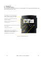
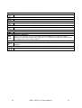
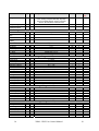
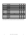
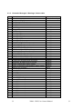
User Manual Eproms XDM - XDE Microface E 24VAC Hiromatic E ENGLISH cod.273099 rev.12.12.05 INDEX 1 Introduction ............................................................................................................................................................................................... 2 1.1 2 Foreword ................................................................................................................................... 2 Hardware................................................................................................................................................................................................... 3 2.1 Microface Evolution 24V AC ................................................................................................... 3 2.1.1 Networking between Microfaces ...................................................................................... 4 2.2 LCD Display ............................................................................................................................. 5 2.3 Eprom........................................................................................................................................ 6 2.4 Humitemp Evolution................................................................................................................. 6 2.5 PTC Temperature Sensor .......................................................................................................... 6 2.6 I-Board / TAM Module............................................................................................................. 6 2.7 Hiromatic E ............................................................................................................................... 7 2.7.1 Backside View, Jumpers and Eprom Position .................................................................. 7 2.8 Power Supply Module for Hiromatic E (24V only).................................................................. 8 2.8.1 PSM Hardware.................................................................................................................. 8 2.8.2 PSM Connection (24V only)............................................................................................. 8 2.9 Hirobus Cables and other Connection Cables........................................................................... 9 2.10 Microface Addressing ............................................................................................................... 9 2.11 Hardware, Technical Specification ......................................................................................... 10 2.12 Spare Parts List ....................................................................................................................... 11 3 Software .................................................................................................................................................................................................. 12 3.1 The LCD Display .................................................................................................................... 12 3.1.1 How to move through the Values/Parameters of the LCD Display................................ 13 3.1.2 How to enter the Password (PIN) ................................................................................... 13 3.1.3 How to change Parameters.............................................................................................. 13 3.1.4 How to reset Alarms or Warnings................................................................................... 14 3.1.5 Tricks .............................................................................................................................. 14 3.1.6 The LCD Parameters....................................................................................................... 15 3.1.7 The Microface E LCD Display Warnings / Alarms........................................................ 19 4 Hiromatic E.............................................................................................................................................................................................. 22 4.1 Hiromatic E Layout................................................................................................................. 22 4.2 Meaning of the different Symbols in the Main Window ........................................................ 23 4.3 How to Move in the Hiromatic Windows............................................................................... 24 4.3.1 Hiromatic E Icons ........................................................................................................... 25 4.3.2 Hiromatic Parameter List ................................................................................................ 27 4.3.3 Hiromatic Messages / Warnings / Alarms table.............................................................. 32 5 Connection Guide ................................................................................................................................................................................... 34 1 XDM – XDE User Control Manual 1 1 1.1 Introduction Foreword This User Manual describes the Microface E Control System. It contains information concerning the architectures of the control systems as well as the settings required to obtain the desired behaviour of the Unit. In the following sections first the Hardware, and later the Software (Firmware) are explained in detail. The Eprom for Microface E allows the SNMP protocol (See manual cod. 272703 rev. 12.12.05) only for remote monitoring vice versa, the Eprom mounted on Hiromatic E allows using the Hirovisor-IP supervisor system 2 XDM – XDE User Control Manual 2 2 Hardware 2.1 Microface Evolution 24V AC The Microface Evolution is a microprocessor-based electronic card, which is able to manage the devices and the sensors installed in the unit. Microface E is installed in the electrical panel of indoorunits together with a User-interface module (“LCD Display”), which allows to read/set/reset values, parameters and alarms. In outdoor- or ceiling mounted units the LCD Display is mounted in a box with extension cable, which allows placing it on a reachable position. To get access to the Microface E connections and Jumpers the LCD Display (if present) has to be removed from its 4 mounting pins. Take care not to pull out the connecting cable when removing the LCD Display! As the Microface E is the “Heart” of the System, which controls all Functions of the Unit, some Jumpers have to be set in order to set-up the control board according to the requested Functions. Most of these Jumpers are already correctly set in the factory, only the Jumpers for the unit’s address (“A”) has to be set in the field, during start-up of the Unit. Never add / remove Jumpers when Microface is under power! A Backup battery EWE AI EPROM E/F SG HM quick plug-in connector to "local" LCD display. ES I-Board RS485 for direct communication to HISNMP. quick plug-in connector to Humitemp sensor, "remote" LCD display. HIROBUS quick plug-in connector to Hiromatic E or next/previous Microface. HIROBUS quick plug-in connector to next/previous Microface. JUMPERS: EWE: EEPROM write enable. Always set this jumper. A: Address setting. See chapter “Networking” for Details. Units, not connected to others: NO Jumper. AI: Analogue Inputs selection. See details on Microface Connection Guide at the end of the manual. E/F: EPROM / Flash memory selection jumper. Set the jumper when EPROM is installed. Do not set this jumper when Flash memory is installed. SG: Subgroup ID setting. See chapter “Subgroup Microfaces” HM: Comb connector for I-Module (present when humidifier is installed). ES: EPROM /Flash memory size selection jumper. Set jumper between middle and right pins for 1 or 2 Mbit size memory devices. Set jumper between middle and left pins for 4 Mbit size memory devices. Figure 1 – Microface E 24V AC and 24V DC with connectors and jumpers. 3 XDM – XDE User Control Manual 3 2.1.1 Networking between Microfaces Several units can be connected together via Hirobus for standby and rotation function as well as to keep under control the entire system from one common Hiromatic E. The maximum number of units to be connected is 16, this number reduces to 8 is a HIROLINK is connected to the common Hiromatic. If a HISNMP is connected directly to the Microface, 16 units can be connected. The bus-cable must be wired from 1st unit to the 2nd, from 2nd to the 3rd etc. “Star” or “Ring” connections are not allowed at all. The Maximum length of the Hirobus-cable is 300 meters, counting all connection cables together. The single distances are not of interest, as long as the total length of all cables together doesn’t exceed 300 meters Please note that a wrong connection could cause serious problems to the electronic devices (Microface and Hiromatic); for this reason we strongly recommend you to use only first quality products or to buy the cables directly from your sales reps.. Before connecting the cables to the Microface a check with CableTester (see Spare Parts List, Chapter 2.12) has to be performed. EPROM MICROFACE E EPROM MICROFACE E HIROBUS: Six wires flat screened cable TO HIROMATIC E (if installed) eight wires flat cable. The cable must be screened if Hiromatic is not installed on the door of the unit. TO NEXT MICROFACE NOTE : CONNECT THE SCREEN OF THE FLAT CABLE TO THE CLOSEST "PE" (EARTH) OF THE ELECTRICAL PANEL ON BOTH SIDE OF THE CABLE. HIROBUS CABLES MUST BE INSTALLED INSIDE SUITABLE CONDUITS, SEPARATE FROM THOSE OF POWER TRANSMISSION CABLES. Figure 2 connecting Microfaces. Cables to be used: see Figure on page 9. 4 XDM – XDE User Control Manual 4 2.2 Backlit LCD LCD Display There are two different Displays available: “Local” Display “Remote” Display 23.0 Up-push-button Both Displays have the same Front-View: Down-push-button Enter push-button Red LED Green LED Yellow LED Figure 3 – LCD Display Front View (with plastic cover) Just the backside connections are different, because of the different connection types to the Microface E: Local or Remote Display. "LOCAL" LCD DISPLAY "REMOTE" LCD DISPLAY Six poles connector for the connection to the external panel Switch and LED FERRITE Alternative !! CONNECTION TYPE A: 4 wires flat cable (410 mm max. length) MICROFACE E HT CONNECTION TYPE B (HIROBUS): 8 wires screened flat cable. Screen connected on both sides to earth. MAX LENGTH: 20 m. to Humitemp The T-Adapter is necessary only when both "Hirobus" sensors and "remote" LCD display must be connected the same. Otherwise the it can be connected directly to the Microface E “HT” Jack. Figure 4 – Local and Remote Display Backside Never use cables longer than 410 mm (Local Display) or longer than 20m (Remote Display)! 5 XDM – XDE User Control Manual 5 2.3 Eprom The Eprom is the device, which stores the Program; the Microface has to work with. It doesn’t store any user-settings; this is done by the Microface itself (in the RAM and the E2Prom). The Version Name and the Number are printed on the Label of the Eprom. The following Eproms are today in use for Standard XDF Units (the xxx is a placeholder for the actual Version): XDM-1.60.xxx 4 Mbit flash for Microface E XDEL1-1.60.xxx 4 Mbit flash for Hiromatic E Figure 5 - Eprom Un-power the Microface before mounting/dismounting the Eprom. Remove Eprom only with special tool; never use a screwdriver. For correct direction of mounting please refer to figure 1 in Chapter 2.1 for Microface, and figure 10 in Chapter 2.7.1 for Hiromatic. Compare the Mark in the Eprom with the direction in the Drawing. 2.4 Humitemp Evolution The Humitemp is a combined Temperature / Humidity Sensor. If connected, the Microface will use the values of the Humitemp for control. It is connected to the Microface through Hirobus-Cable (max. length: 25 m). Figure 6 – Humitemp 2.5 Temperature Reading Humidity Reading PTC Temperature Sensor PTC Sensors are temperature-sensors, changing the resistance according to the temperature (positive temperature coefficient). The connection is 2 poles. The length of the cable sensor ranges from 2 to 10 meters. Measuring Element Cable for the Figure 7 – PTC Sensor 2.6 I-Board / TAM Module The I-Board for CCAC Units is the current transformer for the Humidifier (cylinder Type). The I-Board consists of one Current Transformer-Coil (one phase of the power supply for the humidifier must be wired through the hole); and 1 output relay. The I-Board is simply plugged onto the Microface, see figure1 in Chapter 2.1 for the position. Figure 8 – I-Board 6 XDM – XDE User Control Manual 6 2.7 Hiromatic E Hiromatic E is a microprocessor-based electronic device, which makes it possible to control the functions of one or more Microface devices. Hiromatic E offers numerous advantages of programming the units as well as to optimise their operation using various features, see chapter 3, Software. MICROFACE E Hiromatic can be fixed on the front panel of the unit, simply connecting the HIROBUS cable as shown in figure 9 EPROM HIROMATIC (BACKSIDE) Figure 9 – direct Connection between Microface and Hiromatic FERRITE 2.7.1 Eight wires screened flat cable (max length: 10 m) (Use direct connection when the distance between Microface and Hiromatic is less than 10 m) Backside View, Jumpers and Eprom Position Transformer Board Display Board Backup Battery C E Figure 10 Hiromatic Evolution Backside A EPROM D Hironet Hirobus F Description of the Jumpers: A: C: D: E: F: Eprom (2M) / Flash Size (4M): Middle + Upper Jumper: 2 or 4 MBit (std. setting) Middle + Lower Jumper: not used. Write Disabling: do not set this Jumper Interface Selection: both Jumpers as indicated in Drawing: RS 485 (std. setting) No Jumpers set: RS 422 Contrast Selection: Middle + Left Jumper: Variable Contrast Middle + Right Jumper: Fixed Contrast Flash download: not supported yet. Do not set this Jumper Please take special care about the Jumpers when installing a new (Spare Part) Hiromatic! 7 XDM – XDE User Control Manual 7 2.8 Power Supply Module for Hiromatic E (24V only) 2.8.1 PSM Hardware Hiromatic E can be supplied mounted in an independent electrical panel containing a power supply module as well (PSM Power Supply Module), if the Distance to the next Microface is more than 10 Input 24VAC / 24VDC+ 24VAC / DC GND not used Output 24VAC / 24VDC+ 24VAC / DC GND (max 6.5A) Fuse 8x20mm, 250V, T1.6A from Microface / Macroface to Hiromatic meters. The PSM Module itself needs a power of 24V AC or 24V DC. Figure 11 – PSM Module 2.8.2 PSM Connection (24V only) The connection between Hiromatic E and the PSM is carried out in the factory by means of an eight wires HIROBUS cable. The PSM should be connected to Microface through a six wires screened HIROBUS cable; the screen needs to be grounded in both terminals. When the system consists of more than one unit, Hiromatic can be connected to any unit where Microface has a free HIROBUS connector (usually either the first or the last one of the Microface chain). HIROMATIC (BACKSIDE) EPROM MICROFACE E FERRITE Six wires screened flat cable. (Use this connection when the distance between Microface and Hiromatic is greater than 10 m). The length may vary within the total limit of 300 m (max. Hirobus overall length). Eight wires screened flat cable (max length: 10 m) Power Supply for PSM: 24VAC; 24V DC POWER SUPPLY MODULE (PSM) Figure 12 Connection of Microface LAN to Hiromatic E with PSM. 8 XDM – XDE User Control Manual 8 2.9 Hirobus Cables and other Connection Cables The connections between various Microfaces, Hiromatic, display and sensors are carried out with cables having a different number of wires and different connectors. Following you can find how these cables have to be done. For the type of cable and connectors refer to the spare part list included in this manual. Please note that a wrong connection could cause serious problems to the electronic devices (Microface and Hiromatic); for this reason we strongly recommend to use only first quality products or to buy the cables directly from your sales reps.. EIGHT POLES MODULAR JACK Figure 14 EIGHT WIRES FLAT CABLE. USE SCREENED CABLE WHEN CABLE IS RUNNING OUTSIDE THE UNIT. Eight-wires; eight poles connector HIROBUS cable, for Hiromatic E or Humitemp connections; for connection between Microface E and the remote LCD Display EIGHT POLES MODULAR JACK (USE ONLY THE CENTRAL SIX POLES) Figure 15 SIX WIRES SCREENED FLAT CABLE Six-wires (Pin 1 and 8 not connected) HIROBUS cable, for Microface E connections, eight poles connectors. This cable must be screened. FOUR POLES MODULAR JACK FOUR WIRES FLAT CABLE Figure 16 4 wires flat cable for local LCD Display, four poles connectors. 2.10 Microface Addressing When Microfaces are connected with HIROBUS, it is necessary to assign a different address to each of them, by means of a group of jumpers on the Microface. The jumper position is described in figure 16. The units must be addressed starting from #1, consecutively. The bus-cable doesn’t necessarily need to go in order of the addresses; it could also be wired 1-5-4-2-3, for example. Figure 17 – Address Jumpers 9 #1 #5 #9 #13 #2 #6 #10 #14 #3 #7 #11 #15 #4 #8 #12 #16 XDM – XDE User Control Manual 9 2.11 Hardware, Technical Specification Microface E 24V AC 24VAC, ± 10%; 50 Hz 7 2 (max. 24V – 1A) 2 8 3 -10 (not condensing) to +65°C 0 (not condensing) to +55°C Power Supply Digital Out (Triac) Digital Out (Relay) Analogue Out (0-10V) Analogue In (resistive) Analogue In (resistive / 0-10VDC) Storage Temperature Operating Temperature Range Humitemp E Power Supply Temperature range Humidity range Minimum airspeed required Temperature precision Humidity precision (@25°C) 10VDC (from Hirobus) 0 to 50°C 20 to 90% 0,5 m/s ± 0,5°C 40 to 65%: ±2 %r.H. 20 to 90%: ±4 %r.H. PTC Temperature sensor Cable length Temperature range Point of calibration 1,5 m and 10m -28 to 100°C 2000Ω at 25.0°C Hiromatic E Power Supply Graphic Display Mounting hole 10VDC (from Hirobus) Backlit, 200 x 64 pixels 175 x 150mm Power Supply Module (PSM) Power supply Output 24VAC, ± 10%; 24VDC, ± 20% 10VDC (Hirobus, stabilised); 24VAC, ± 10%; 24VDC, ± 20% (filtered) I-Board (Current transformer) Current Range Digital Out (Relay) 10 0 – 30A 1 (max. 24V – 1A) XDM – XDE User Control Manual 10 2.12 Spare Parts List DESCRIPTION 11 CODE Switch + Led 255039 Microface E (Evolution) 24 AC board 275297 Local LCD display for Microface 275098 Remote LCD display for Microface 275662 I-Board / TAM Module 275099 Probe temperature PTC 275183 Probe PTC 2 kohm L = 10 m 275155 Probe Temp. + Hum. Humitemp 275181 EPROM Microface E XDM160*** 276224 EPROM Hiromatic E XDE-L1 160*** 276225 Hiromatic Evolution 275691 LWD (Leakage Water Detector) 275353 Flat cable 8 way M-M L = 1 m 275607 Flat cable 8 way M-M L = 10 m 275610 Flat cable 8 way screened (specify length) 275626 Module PSM 24/24-10 for Hiromatic 275316 Plastic holder for Microface only 270002 Plastic holder for Microface and LCD display 270003 Hirobus / Hironet Cable Tester 480061 Hirobus / Hironet Interface Tester 480060 XDM – XDE User Control Manual 11 3 3.1 Software The LCD Display The interface module consists of a backlit LCD and of three push buttons that permit an easy access to the unit parameters. Writing access is protected by a password. Backlit LCD 23.0 Up-push-button Down-push-button Enter push-button Red Led Green Led Yellow Led Figure 18 Interface module between Microface and operator (front view). There are three LED’s: the yellow Led to indicate the unit is power supplied, the green one lights up when the unit is in operation and the red one signals either an alarm or a warning condition. On the LCD the following symbols will be displayed: 23.5 SET °C(%) ! RH STANDBY Figure 19 LCD Layout The snow symbol is active when the unit is in cooling operating mode. The fan symbol is active when the unit is running, that means that the fan is operating. The sun symbol is active when the unit is in heating mode The alarm triangle is ON when either a warning or an alarm is active ! STANDBY SET RH % °C 12 The „STAND BY“ string will be displayed when the unit is in the stand-by mode (not running) The ‘SET’ string will be displayed after the correct password is entered; the presence of this string on the display confirms the full access to the displayed parameters. The „RH“ and “%” strings appear when relative humidity is displayed on the LCD. The „°C“ string appears when temperature is displayed on the LCD. XDM – XDE User Control Manual 12 3.1.1 How to move through the Values/Parameters of the LCD Display All Values and Parameters are listed up just one after the other. To jump the next parameter, simply the “down” button has to be pressed. The name of the first parameter ($ is not a real parameter, but only an example) will be displayed for one second, while the value itself will be displayed for two seconds (alternating) (this position is also considered as the “Home”. “Up” and “down” push-buttons The name of the second parameter ($is not a real parameter, but only an example) will be displayed for one second, while the value itself will be displayed for two seconds (alternating). “Up” and “down” push buttons to reach the other parameters. $ 65 $ 65 3.1.2 How to enter the Password (PIN) Without password or by entering the wrong password, read only access is given, without the possibility to change values. To enter a password in Microface, select the “Pin” parameter by pressing the “down” push-button as often as necessary. When pressing “Enter” (↵), a 0 will be displayed as first digit on the left and will be followed by two dashes (a password is made of 3 digits). Change the numeric value by pressing the “up” or “down” push buttons. After having obtained the required numeric value, press “Enter” (↵) to go to the following digit. Pressing “Enter” (↵) after having selected the last password digit, the parameter (“Pin”) name will be displayed again. If the correct Password is entered, the desired modifications can be made. Reaching the next changeable Parameter, the LCD Display will show a “SET” string, which is the confirmation, that the PIN was entered correctly. Different Password-Levels give different “Rights”: Level 0 Level 1 Level 2 Level 3 Level 4 Level 5 Level 6 Read only Customer Level Service Low Level Not used Sensor Calibration Service High Level Service contacts The password is stored, until the first parameter / value (“Home”) of the list is displayed again. Never leave the Unit without jumping back to “home” (pressing “Enter” and “UP” together). 3.1.3 How to change Parameters To change the value of a parameter (possible only when the Password “PIN” has been correctly inserted), scroll the list using the “up” and “down” push-buttons until the desired parameter is displayed and press “Enter” (↵). By pressing the “up” and “down” push buttons, it is possible to change the corresponding value; after having obtained the required value, press enter (↵) again. The display will show again the name of the parameter alternating with the new value. 13 XDM – XDE User Control Manual 13 3.1.4 How to reset Alarms or Warnings When an alarm is triggered, the red alarm LED is lit on the LCD Display Module and the corresponding symbol is shown in the Display. The Alarm section can be reached by pressing the “up” push-button when the first parameter is on the display; alarms are pointed out according to their code order. After having entered the alarm section, the alarm code is displayed and every second the code is replaced by the coded description. Pressing the “Enter” key (↵), when an alarm code is displayed on the LCD, all the active alarms will be reset. After the reset operation, all the still active alarms will be shown again. If there are no more active alarms, the first parameter / value of the list will be displayed again. 3.1.5 Tricks To quickly reach the parameter at the bottom of the list, press “Enter” (↵) together with the “down” push-button. To quickly reach the parameter at the top of the list, press “Enter” (↵) together with the “up” push-button. 14 XDM – XDE User Control Manual 14 3.1.6 The LCD Parameters See chapter 3.1.1 how to move through the Menu and how to enter the Password. The order of the following table is according the menu-layout of the LCD. The range of selectable values is available on Hiromatic E Parameters list LCD Parameter name Description User setting ( Return Temperature This value, together with the supply temperature, is used to calculate the speed of evaporator fan within the range defined with the & and & LCD parameters in a delta T (( minus () of 5-10°K. This function is possible only setting one of the two analogs output as ECFan This value is used for cooling and heating control management This value is used humidification and dehumidification control management Actual temperature set point in use Read only Actual humidity set point in use Read only Actual condenser pressure value: this value is used by the control to manage the condenser fan speed Actual compressor discharge pressure: this value is used by the control to manage the compressor power reduction If set to !# the humidifier water drain valve will be activated for a time of 30 seconds; the parameter jumps automatically to ! See 3.1.2. Chapter Number of unit connected in the Hirobus LAN (Local Area Network) Number of standby units Read only ( Supply Temperature Return Humidity ( Actual Temperature Set point Actual Humidity Set point % Actual HP1 pressure value % Actual HP1 pressure value * Manual Humidifier Drain %# Password #( Number of Unit in Network &( Number of StandBy Units *"( Rotation Enabled *"" Perform Rotation ,( Auto Restart * Remote Enabled 15 Enables the units rotations Used to force an units rotation Unit actives its devices (Fan, Compressor, Heating.....) with the delay set every time the unit is powered On. The delay set is multiplied per the Hirobus ID, i.e. if set to 5 the 1st unit will start with a delay of 5 seconds, the 2nd unit will start after 10 seconds, the 3rd after 15 seconds and so on If set to #" the ON OFF key of Hiromatic E will be disabled, if set to 2& it is enabled XDM – XDE User Control Manual Read only Read only Read only Read only --- --- 15 LCD Parameter name Description User setting " Backup Cooling Output " $ &%( &% #" ( &( %( % & , , & %*" % + The Output 0 is used to inform the Rack that the backup cooling has to be activated. This Output can be set normally closed or normally open in absence of alarm. NOTE: This parameter has to be set to # on all units that are located between the first and the last units; the parameter has to be set to #/! on the first and last units. In case of two units and one rack only the parameter has to be set to #. Backup Cooling If set to #" the Output 0 (see " parameter) never will be in Activated alarm condition when the unit is switched OFF by Hiromatic By On/Off or Local On Off key Damper Control If set to 2& and the dampers are not in the right position the unit will be forced to OFF Temperature Set point This parameter is used to define the needed temperature set point Humidity Set point This parameter is used to define the needed humidity set point Number of Parameter locked to (Single DX unit) Compressors Free cooling Type Parameter locked to " (No free cooling) Standard Settings Forcing this parameter to 2& all parameter marked with symbol will assume the factory settings. The parameter goes automatically to #" as soon as the factory setting is modified Temperature Range of values centred on temperature set point used by the Proportional Band control to manage the cooling and heating devices. Humidity Range of values centred on humidity set point used by the Proportional Band control to manage the humidification and dehumidification devices. Electrical Heating Number of electrical heating steps available on unit for Step heating control Heating Dead Band Allows to shift the heating band from temperature set point; it is normally used to active the heating at lower temperature. If set a negative value the heating band is shifted over the cooling band Humidifier Enabled Enable disable the humidification control Humidifier Type Defines the type of humidifier mounted on board Humidifier Supply Defines the humidifier supply voltage Humidifier Steam rate Defines the steam rate production Humidifier Control The humidification control can be done in two different modes: Proportional and On Off. %*": the steam rate production value changes between the minimum selectable (30%) and the value set according to the humidity deviation from humidity set point (within the humidification band) !#!: the humidifier is activated as soon as the humidity deviation reaches the limit of humidity band Humidifier Current Actual humidity current absorbed value 16 XDM – XDE User Control Manual 16 LCD Parameter name Description User setting , Humidity Dead Band Dehumidification Enabled * Electrical Re-Heating Allows to shift the humidity band from humidity set point Enable disable the dehumidification control Enable the use of electrical heating when the dehumidification is active Allows defining when to stop the dehumidification: the value set is considered the deviation from the right limit of dehumidification band Allows to shift the dehumidification band from humidity set point If the related sensor is installed is possible to active a warning (unit continue to operate) or an alarm (unit is switched off) in case of water presence Actual liquistat sensor value The output will supply a 0-10 volt signal according to the value set: it must be set to the unit is equipped with the EC-Fan The output will supply a 0-10 volt signal according to the value set; it has to be set to "# when the unit is equipped with the condenser control If set as warning only the heating and humidifier are disabled, if set as alarm the unit will be stopped If an analog output is set to &, the speed of the evaporator fan is defined by this parameter Minimum voltage signal value used on evaporator fan speed control when an analog output is set as (see also () Maximum voltage signal value used on evaporator fan speed control when an analog output is set as (see also () Defines the delay time considered by the control before to active the LP event at each compressor start If set to 2& the TH1 event will be activated when the compressor protection is active vice versa, it will be ignored. NOTE: in case of Thermal protection the compressor is disabled for a time of 30 minutes At each compressor start the minimum compressor power is 50 % for the time set It defines the first supply temperature limit value; if reached the ( event is activated and the speed of the evaporator fan is forced to the maximum value. The event is ignored for 5 minutes every time the unit is switched to ON then the condition has to persist for a time of 10 seconds minimum. The speed will back under control as soon as the temperature is equal or lower then the temperature set point Dehumidification Hysteresys Dehumidification Dead Band &( Liquistat Liquistat sensor value # Analog Output 0 # Analog Output 1 Fan Failure && Fan Speed Standard ' Fan Speed Limit 1 & Fan Speed Limit 2 % Low Pressure Delay ( Thermal Compressor ( Min. Compressor Power Time ( High Temperature level 1 17 XDM – XDE User Control Manual 17 LCD Parameter name Description ( Low Temperature level 1 First low supply temperature limit value: if the limit is reached and the condition persists for 10 seconds the ( event is activated and the compressor will be stopped. Compressor will be activated as soon as the temperature is greater then the temperature set point + cooling band. The event is ignored for 15 minutes every time the compressor switched to ON; any relation from Unit On High Humidity level 1 First high return humidity limit value: if the limit is reached the event is activated; this event is ignored for 5 minutes every time the unit is switched to ON Low Humidity level 1 First low return humidity limit value: if the limit is reached the event is activated; this event is ignorer for 5 minutes every time the unit is switched to ON High Temperature Second high supply temperature limit value: if the limit is ( level 2 reached and the condition persists for 10 seconds, the ( event is activated and the unit will be forced to OFF; this event is ignored for 5 minutes every time the unit is switched to ON Second low supply temperature limit value: if the limit is ( Low Temperature level 2 reached and the condition persists for 10 seconds, the ( event is activated; this event is ignored for 5 minutes every time the unit is switched to ON High Humidity level 2 Second high return humidity limit value: if the limit is reached the event is activated; this event is ignored for 5 minutes every time the unit is switched to ON Low Humidity level 2 Second low return humidity limit value: if the limit is reached the event is activated; this event is ignorer for 5 minutes every time the unit is switched to ON Allows to make an offset on supply temperature sensor Supply Temperature Sensor Calibration reading Allows to make an offset on return temperature sensor Return Temperature Sensor Calibration reading Allows to make an offset on return humidity sensor reading Return Humidity Sensor Calibration If set to YES the unit will be forced on manual mode and all (&( Auto Test outputs will be activated step by step than the unit goes back to operate in the usual way 18 XDM – XDE User Control Manual User setting 18 3.1.7 The Microface E LCD Display Warnings / Alarms Num. Code Description % High Pressure % Low Pressure ! Electrical Over Heating Fan Failure Fan Failure Clogged Filter Water Leakage Water Leakage Humidifier Failure Humidifier High Current Humidifier failure , Humidifier failure + Humidifier Cylinder Worn ) High Supply Temperature Level 1 19 Type Alarm: the event is activated with a delay of 20 seconds; compressor is stopped and the unit is forced to OFF. Alarm: the event is activated after the delay set (see % parameter); compressor is stopped and the unit is forced to OFF. Warning: the event is activated with a delay of 20 seconds; heating is stopped, unit remains ON Warning: the event is activated with a delay of 100 seconds at each Unit On then the condition has to persist for 10 seconds. Heating and Humidification are disabled when the warning is active; unit remains ON Alarm: the event is activated with a delay of 100 seconds at each Unit On then the condition has to persist for 10 seconds, unit is forced to OFF Warning: the event is activated with a delay of 60 seconds, unit remains ON Warning: the event is activated with a delay of 25 seconds of delay; unit remains ON Alarm: the event is activated with a delay of 25 seconds of delay; unit is forced to OFF Warning: no delay; the event is activated when the “Humidifer Type” parameter is set to EXT and the “User Input 2” parameter is set to LSI. Set “User Input 2” parameter to “Not Used” to remove the warning Warning: no delay; the event is activated when the current absorbed is higher then 35A or 150% higher then the limit defined by the control according to the humidifier type Warning: the event is activated when the measured current is lower then 1A for a time of 15 minutes minimum (no water) Warning: no delay; the event is activated when the measured current changes from a certain value to 0 in few seconds Warning: the event is activated when the measured current 50% higher then the value, considered by the control according to the humidifier type, for a time of 48 hours minimum Warning: the event is ignored for a time of 5 minutes at each unit ON then; the condition has to persist for a time of 10 seconds minimum. When the event is active the speed of evaporator fan is forced to 100%. The event is automatically reset as soon as the temperature is equal or lower the temperature set point XDM – XDE User Control Manual 19 Num. Code Description ) Low Supply Temperature Level 1 High Return Humidity Level 1 Low Return Humidity Level 1 ( High Supply Temperature Level 2 ( Low Supply Temperature Level 2 High Return Humidity Level 2 Low Return Humidity Level 2 Conditioner Working Hours Exceeded Compressor Working Hours Exceeded Humidifer Working Hours Exceeded && Supply Temperature Sensor Failure *& Return Temperature and Humidity Sensor Failure &# Sensors not Available Water Presence Sensor Failure %) Pressure Transducer HP1 Sensor not Available & %) Pressure Transducer HP1 Sensor not Available #"$ No Power Active #( No Connection to Unit 1 ) Compressor Thermal Protection 20 Type Warning: the event is ignored for a time of 5 minutes at each unit ON then; the condition has to persist for a time of 10 seconds minimum When the event is active the compressor is stopped. The event is automatically reset as soon as the temperature is higher then the temperature set point. Warning: the event is ignored for a time of 5 minutes at each unit ON Warning: the event is ignored for a time of 5 minutes at each unit ON Warning: the event is ignored for a time of 5 minutes at each unit ON then; the condition has to persist for a time of 10 seconds minimum, unit is forced to OFF Warning: the event is ignored for a time of 5 minutes at each unit ON then; the condition has to persist for a time of 10 seconds minimum; unit remains ON Warning: the event is ignored for a time of 5 minutes at each unit ON Warning: the event is ignored for a time of 5 minutes at each unit ON Warning: the event is activated as soon as the actual working hours value reaches the limit Warning: the event is activated as soon as the actual working hours value reaches the limit Warning: the event is activated as soon as the actual working hours value reaches the limit Warning: the event is activated with a delay of 15 seconds; unit is forced to OFF when the event is active Warning: the event is activated with a delay of 15 seconds; unit is forced to OFF when the event is active Alarm: the event is activated with a delay of 15 seconds; unit is forced to OFF when the event is active Warning: the event is activated with a delay of 25 seconds; unit remains ON Warning: the event is activated with a delay of 15 seconds; the condenser fan speed value is locked to 50% when the event is active Warning: the event is activated with a delay of 15 seconds; the compressor power request is 20% reduced when the event is active Warning: no delay; unit if forced to OFF Warning: 30 seconds of delay; the standby unit is forced to ON Alarm: the event is activated with a delay of 20 seconds; unit is forced to OFF and the compressor is disabled for a time of 30 minutes. The event is ignored if the “Compressor Thermal Enabled” parameter is set to #" XDM – XDE User Control Manual 20 Num. Code Description %* Compressor Power Reduction Active % Wrong Damper Position 21 Type Warning: if the pressure detected by the HP2 sensor persists over the limit set (see parameters on “Condenser control 2/2” Hiromatic E page) the compressor power request is reduced of the 20% Alarm: the event is activated with a delay of 20 seconds; unit is forced to OFF (see also % parameter). The damper condition is verified on both unit condition: On and OFF XDM – XDE User Control Manual 21 4 4.1 Hiromatic E Hiromatic E Layout The front panel of Hiromatic E consists of a backlit graphic LCD, of eight push buttons that permit input function and of two LED. Cursor Buttons: to move inside the Menu; Left or Light: To go up to the Main Window or back to the previous window Push-button to start/stop the system and the units (if enabled). Help Key: opens Online-Help for the selected Parameter This LED (orange) will be ON when the unit is power supplied Alarms and warnings reset. GREEN when the Unit is in Operation, YELLOW if the Units is in Warning condition, RED if the Unit is in Alarm condition ENTER Button, to set Parameters Figure 20 - Hiromatic E Front View 22 XDM – XDE User Control Manual 22 4.2 Meaning of the different Symbols in the Main Window Return Air Temperature (if on the top-right SYSTEM is indicated, it is the average of all units with system on. If UNIT X is indicated, it is the return air temperature of the specific unit. This is valid for all indications in Hiromatic Display. Return Air Humidity of the System / the Unit. Supply Air Temperature of the System / the Unit This Bargraph gives Information about the actual Evaporator Fan Speed, either for the System or for a specific Unit. This Bargraph gives Information about the actual used Cooling-recourses in Operation, either for the System or for a specific Unit. This Bargraph gives Information about the actual used Heating-recourses in Operation, either for the System or for a specific Unit. This Bargraph gives Information about the actual used Dehumidification-recourses in Operation, either for the System or for a specific Unit. This Bargraph gives Information about the actual used Humidification-recourses in Operation, either for the System or for a specific Unit. This Bargraph gives Information about the next Maintenance time (mm-yy) This Field of the Window informs about time, date, the status of the System / Unit. 23 XDM – XDE User Control Manual 23 4.3 How to Move in the Hiromatic Windows There are two ways to enter the menus: with or without Password. Entering without Password allows reading the values (except Password Menu and Calibration Menu); entering with Password allows also changing Parameters. Left /R ight to the Menu es Without Password: Press ENTER or DOWN; press DOWN once more, and then ENTER. With Password: Press ENTER or DOWN; ENTER to select first digit of Password; select with UP or DOWN, press RIGHT for the next Digit; UP or DOWN to select, etc. After having selected the correct Password, press ENTER. Press DOWN to select the Enter-String, and press ENTER to jump into the Menu-Icons. Depending on the Password Level some of the Menus will be read/write, some of the read only. Select the Window with LEFT-RIGHT-DOWN, Press ENTER to select the first Icon, Press LEFTRIGHT-UP-DOWN to select the Icon (The Menu), and press ENTER to get in. Left/Right Enter Up / Down Enter select menu Enter 24 into menu XDM – XDE User Control Manual 24 4.3.1 Hiromatic E Icons Units Status Overview This Window gives Information about the number of connected units and the status of each unit. The String “UNIT” appears only for those Units, which are configured in the Parameter: “Number of Units”. If beside the “UNIT” String no Status appears, it means that the unit was disconnected from the Hirobus Graphic Data Records For the System, as well as for each single unit an 8-days Graphic Data Record as well as a 24-hours Record for both Temperature and Humidity are available. The temperature/humidity scale can be adjusted (Enter- UP/DOWN). The Records are stored also after power off Status Report The Status Report contains the last 200 events in order of appearance, which occurred to the System, as well as to each single unit. From the System-Status-Report (a collection of events of all units) it is possible to reach the Unit-Status-Report (a collection of events for the selected unit only) of the single units by pressing the RIGHT key Service Contacts Allows defining the needed information to contact the local area service assistance. The relative information regarding the closest local service assistance is automatically showed according to the selected country. This message is showed every time that the event registration is accessed or easer pushing the “Help on Line” button System Settings Allows defining the language as well as the date and time of Hiromatic E Standby Settings Allows defining the rotation and standby rules System Setup Allows defining the number of units connected on HIROBUS network and the HIRONET communication for Hirovisor IP Graphic Data Records For each single unit an 8-days Graphic Data Record as well as a 24-hours Record for both Temperature and Humidity are available. The temperature/humidity scale can be adjusted (Enter- UP/DOWN). The Records are stored also after power off Status Report The Status Report contains the last 3 events in order of appearance, which occurred to the single unit. From the System-Status-Report (a collection of events of all units) it is possible to reach the Unit-Status-Report (a collection of events for the selected unit only) of the single units by pressing the RIGHT key Unit Overview The actual Temperatures and humidity as well as the actual set points values are shown Unit Settings Unit auto restart and SNMP addresses settings Control Parameters Temperature set point, Humidity set point and evaporator fan speed settings 25 XDM – XDE User Control Manual 25 Warning and Alarms High and Low Temperature And Humidity warnings settings Working Hours Working hours limit settings Service Manual operation and status of Microface E Board input are available Calibration Allows performing a sensors offset if required Unit Configuration All parameters used for Temperature and humidity control are available Next Maintenance Calculation For service personnel only: all information about working hours, numbers of alarms, numbers of starts are available for each device. The Wellness bar graph indication is built according to the unit working condition Condenser Control For service personnel only: condenser control as well as compressor power reduction settings Navigator Board Auxiliary board for refrigerant pressure reading 26 XDM – XDE User Control Manual 26 4.3.2 Hiromatic Parameter List The value indicated on the “std. set” column is the factory setting; the value can be modified in order to have the unit’s correct operation in relation to the installation type. We advised to transcribe the unit configuration parameters into the “User Set” column and keep the manual inside the unit Parameter Name Nr. R/W Range Res. Std.Set User Set. System Main window Return Temperature Return Humidity Supply Temperature - R R R -28.0 – 100.0 0 – 100.0 -28.0 – 100.0 0.1(°C) 0.5(%rh) 0.1(°C) - - - R R R -28.0 – 100.0 0 – 100.0 -28.0 – 100.0 0.1(°C) 0.5(%rh) 0.1(°C) - - Country - W - - Line 1 Line 2 Line 3 Line 3 - W W W W None, Austria, Swittz.D, Swittz.F, Benelux D, Benelux F, Germany, France, UK, Hungary, Italy, Poland, Spain Web Contatc Phone Number Service Contact Service email - - 001 002 003 004 005 006 W W W W W W Off , On / 0.1 – 2.0 English mm:hh dd:mm:yy 0 – 127 5 – 60 1 1 (min) 5 011 012 013 014 W W W W 0–1 No, Daily, Mon, Tue, Wed,Thu, Fri, Sat, Sun hh:mm Yes, no 1 - 0 No 00:00 No 021 022 023 024 025 W W R W R 0 – 16 1 – 99 19200 – 20833 No, Yes - 1 1 - 1 1 Yes - - R R R R R -28.0 – 100.0 -28.0 – 100.0 0 – 100.0 -28.0 – 100.0 -7.5 – 31.0 0.1(°C) 0.1(°C) 0.5(%rh) 0.1(°C) 0.1(bar) - - - R -7.5 – 31.0 0.1(bar) - - - R - °C / %rh - - Unit Main window Return Temperature Return Humidity Supply Temperature Contacts System Settings Piezo Frq. Language Time Date Contrast Display Backup Off after StandBy Settings Number of Standby Units Rotation Frequency Rot. Performed At Rotate Once System Setup Number of Units HM ID Number Baudrate Communication HM Eprom V. XDE160*.* Unit Overview Supply Temperature Return Temperature Return Humidity Supply Temperature Actual HP1 Pressure Value Actual HP1 Pressure Value Actual Set Point 27 XDM – XDE User Control Manual 27 Parameter Name Nr. R/W Range Res. Std.Set User Set. Unit Settings Autorestart HM On/Off Enabled IP Address Listen Port 102 103 104 105 W W W W 0 – 999 No, Yes 0 – 255 0 – 2000 1 1 1 0 Yes - W W W 5.0 – 40.0 No, 20 – 80 No, Yes 0.1(°C) 1(%rh) - 20.0 40 No W W W W No, 30 – 100 60 – 100 60 – 100 No, Yes 1(%) 1(%) 1(%) - No 60 90 Yes W W W W No, 1 – 99 No, 1 – 99 No, 1 – 99 No, 1 – 99 1(°C) 1(°C) 1(%rh) 1(%rh) 25 12 No No 142 143 144 145 147 W W W W W No, 1 – 99 No, 1 – 99 No, 1 – 99 No, 1 – 99 nHumi, NComp, Warning, Alarm 2nd Setp, NoPower, Not used, LSI 1(°C) 1(°C) 1(%rh) 1(%rh) - 28 No No No LSI 162 162 162 163 163 163 164 164 164 165 165 165 166 166 166 W W W W W W W W W W W W W W W 0 – 32000 0 – 32000 0 – 32000 0 – 32000 0 – 32000 0 – 32000 0 – 32000 0 – 32000 0 – 32000 0 – 32000 0 – 32000 0 – 32000 0 – 32000 0 – 32000 0 – 32000 1 1 1 1 1 1 1 1 1 1 1 1 1 1 1 32000 32000 32000 32000 32000 - Off, On Off, On Off, On Off, On Off, On Off, On Off, On Off, On 0 – 100 0 – 100 1(%) 1(%) - Control Parameters 1/2 Temperature Setpoint Humidity Setpoint Humidity Compensation 111 112 113 Control Parameters 2/2 FanSpeed Standard Min. EC-Fan Speed Max. EC-Fan Speed Damper Control 121 122 123 124 Sensors Warnings level 1 High Temperature Low Temperature High Humidity Low Humidity 132 133 134 135 Sensors Warnings level 2 High Temperature Low Temperature High Humidity Low Humidity User Input 2 Working Hours Fan Fan Fan Comp Comp Comp Heat Heat Heat Hum Hum Hum Dehum Dehum Dehum Service (Manual Operation 1/3) Manual Fan Comp Heat Hum Drain Dehum Al. Relay Ana 0 Ana 1 191 192 103 104 105 106 191 192 193 194 28 W W W W W W W W W W XDM – XDE User Control Manual 28 Parameter Name Nr. R/W Range Res. Std.Set User Set. Service (Inputs Information 2/3) Remote On Off Damper SX Damper DX Filter Airflow Switch No Power 211 212 213 214 215 216 R R R R R R On, Off Open, Closed Open, Closed Ok, Wa Ok, Al Off, Act - - Service (Inputs Information 3/3) HP LP TH TSR LSI 221 222 223 224 225 R R R R R Al, Ok Ok, Al Ok, Al Ok, Al Off, On - - 312 313 314 W W W -9.9 / +9.9 -9.9 / +9.9 -9.9 / +9.9 0.1(°C) 0.1(%rh) 0.1(°C) - R R W W W W W 1 (Single DX) None No, Yes 1.0 – 30.0 No, 5 – 15 2 – 60 No, 5 – 60 0.1(K) 1(min) 1(%rh) 1(min) 1 None Yes 8.0 No 40 No W W 0, 1 0.0 – 30.0 1 0.1(K) 1.0 - No - 1(%) 0.1(A) 0.1(%) 0 - Calibration Return Temperature Return Humidity Supply Temperature Unit Configuration 1/6 Unit Type: Compressors Unit Type: FC Standard Settings Temp. Prop. Temp. Int. Hum. Prop. Hum. Int 251 252 253 254 254 255 255 Unit Configuration 2/6 Heating steps Heat Dead Band 261 262 Unit Configuration 3/6 Humidifier Enabled Model 271 272 W W Supply Steam Rate Control Amps Nom. / Actual Dead Band 272 273 274 275 276 W W W R W No, Yes 21L, 53L, 53H, 93L, 93H, d3H HT2, HT5, HT9, EXT 230V, 400V, 375V, 465V, No, 30 – 100% On/Off, Prop 0 – 50.0 W W W W W R No, Yes No, Yes 25 – 75 0 – 50.0 No, Wa, Al - 1 0.1(%) (V) No No 50 0 No - W AlarmB, Supers, Cooling1, Cooling2, EC-Fan Humid, Heating, FanSpeed, Ret.Temp, up.Temp, HT.Humi, HeaterB, RadCool, SupCont, Heat 33% 3P.Act1, 3P.Act2, Metric, I-Variex, D.Scroll - EC-Fan Unit Configuration 4/6 Dehum. Enabled El. Reheat Enabled Dehum. Hysteresis Dead Band LWD LWD Input 281 282 283 284 285 285 Unit Configuration 5/6 Analog Output 1 29 291 XDM – XDE User Control Manual 29 Parameter Name Nr. R/W Range AnalogOutPut 2 292 W BackUp Cooling Output BackUp Cooling Activated By On/Off 293 294 Res. Std.Set User Set. - I-Variex W W AlarmB, Supers, Cooling1, Cooling2, EC-Fan Humid, Heating, FanSpeed, Ret.Temp, Sup.Temp HT.Humi, HeaterB, RadCool, SupCont, Heat 33% 3P.Act1, 3P.Act2, Metric, I-Variex, D.Scroll NO, NC No, Yes - NC YES 301 302 W W Warning, Alarm 0–5 1(min) Alarm 3 303 304 W W Enabled / Disabled No, Yes - Enabled Yes 1(M) 1(M) 1(M) - No 0 0 - 1 1 1 1 1 1 1 1 1 - 1 1 1 1 1 1 1 1 1 - 1 1 1 1 1 1 1 1 1 - 1 1 1 1 1 1 1 1 1 - Unit Configuration 6/6 Fan Failure Low Pressure Alarm Delay Fan Failure Alarm** Compressor Thermal Enabled Next Maintenace Calc. (General Maintenance 1/5) Maint. Frequency Max. Bonus Max. Penalty Last Maintenance By: / Reset Calc. Next Maintenance - W W W W W R No, 1 -4 0 -12 0 -12 mm:yy Editable text / Yes, No mm:yy Next Maintenance Calc. (Fan Settings / Diagnostic 2/5) Number of Starts Working Hours AV. Working Time Strarts/Day / Opt/Wor Strarts/Day / Opt/Wor Number of Alarms Actual bonus - R R R W W R R 0 – 32000 0 – 32000 C No, 1 – 240 No, 1 – 240 0 – 32000 0 – 24 Next Maintenance Calc. (Comp. Settings / Diagnostic 3/5) Number of Starts Working Hours AV. Working Time Strarts/Day / Opt/Wor Strarts/Day / Opt/Wor Number of HP/LP/TH Actual bonus - R R R W W R R 0 – 32000 0 – 32000 C No, 1 – 240 No, 1 – 240 0 – 32000 0 – 24 Next Maintenance Calc. (Heat. Settings / Diagnostic 4/5) Number of Starts Working Hours AV. Working Time Strarts/Day / Opt/Wor Strarts/Day / Opt/Wor Number of Alarms Actual bonus - R R R W W R R 0 – 32000 0 – 32000 C No, 1 – 240 No, 1 – 240 0 – 32000 0 – 24 Next Maintenance Calc. (Hum. Settings / Diagnostic 5/5) Number of Starts Working Hours AV. Working Time Strarts/Day / Opt/Wor Strarts/Day / Opt/Wor Number of Alarms Actual bonus 30 - R R R W W R R 0 – 32000 0 – 32000 C No, 1 – 240 No, 1 – 240 0 – 32000 0 – 24 XDM – XDE User Control Manual 30 Parameter Name Nr. R/W Range Res. Std.Set User Set. Condenser Control 1/2 Condenser Set Point Condenser Band Dead Band Cut Off Reset Cut Off At + Min. Cond. Fan Speed Max. Cond. Fan Speed - W W W W W W W 5.0 – 22.0 1.0 – 10.0 0 – 80 5.0 – 15.0 0 – 5.0 0 – 5.0 5.0 – 10.0 0.1(bar) 0.1(bar) 1(%) 0.1(bar) 0.1(bar) 0.1(V) 0.1(V) 16.0 4.0 50 12.0 05 2.5 8.0 - W W R 10.0 – 30.0 10.0 – 30.0 -6.0 – 30.0 0.1(bar) 0.1(bar) 0.1bar) 20.0/24.0 20/3.0 - - R 0 – 100 1(%) - - W W W 0.2 – 10.0 Auto, Manual No, Yes 0.1/%) - 0.5 Auto Yes -7,5 / 31.0 -7,5 / 31.0 - Condenser Control 2/2 HP Warning 1 / 2 Part. Time / Hysteresys Actual Condenser Pressure Actual Condenser Fan Speed Filter Condenser Control I-Variex Active Navigator Board (Pressure Transducer Calibration) Refrigerant Type HP1 491 492 W W R22, R407c Sensor Offset - HP2 493 W Sensor Offset - Actual HP1 Value Actual HP2 value 494 495 R R -7.5 – 31.0 -7.5 – 31.0 0.1(bar) 0.1(bar) ** The Fan Failure Alarm can be deactivated for maintenance reasons and only when the unit is in MANUAL MODE; it is automatically ignored when the unit is operating in AUTOMATIC MODE 31 XDM – XDE User Control Manual 31 4.3.3 Hiromatic Messages / Warnings / Alarms table Code 0 1 2 5 6 7 8 9 10 13 14 15 16 17 18 19 20 21 22 23 24 25 26 27 28 29 30 31 33 34 36 37 39 40 41 42 43 44 45 46 47 48 49 50 Description General Alarm Compressor High Pressure Compressor Low Pressure Electrical Heater Overheated Fan Failure Fan Failure Clogged Filter Water Leakage Water Leakage Humidifier Failure Humidifier High Current Humidifier Failure Humidifier Failure Humidifier Cylinder Worn High Supply Temperature Level 1 Low Supply Temperature Level 1 High Return Humidity Level 1 Low Return Humidity Level 1 High Supply Temperature Level 2 Low Supply Temperature Level 2 High Return Humidity Level 2 Low Return Humidity Level 2 Conditioner Working Hours Exceeded Compressor Working Hours Exceeded Humidifier Working Hours Exceeded Supply Temperature Sensor Failure Return Temperature and Humidity Sensor Failure Sensors Not Available Water Sensor Presence Failure Network Failure Unit ON Unit OFF Standby Mode Power ON Unit Login Power OFF Unit 1 Disconnected Unit 2 Disconnected Unit 3 Disconnected Unit 4 Disconnected Unit 5 Disconnected Unit 6 Disconnected Unit 7 Disconnected Unit 8 Disconnected Unit 9 Disconnected 32 Type Reset, Acknowledge Alarm Alarm Alarm Warning Alarm Warning Warning Alarm Warning Warning Warning Warning Warning Warning Warning Warning Warning Warning Warning Warning Warning Warning Warning Warning Warning Warning Alarm Warning Warning Message Message Message Message Message Warning Warning Warning Warning Warning Warning Warning Warning Warning XDM – XDE User Control Manual 32 Code 51 52 53 54 55 56 57 58 59 64 66 67 70 71 74 75 76 77 83 84 85 88 Description Unit 10 Disconnected Unit 11 Disconnected Unit 12 Disconnected Unit 13 Disconnected Unit 14 Disconnected Unit 15 Disconnected Unit 16 Disconnected Pressure Transducer HP1 not Available Pressure Transducer HP2 not Available ON OFF Hiromatic Not enabled No Power Power ON No connection to Unit 1 Compressor Thermal Protection Out of Memory Compressor Power Reduction Active Dampers Position failure Network Ping Maintenance Done Maintenance Should Be Done Unit Synchronization Heater Working Hours Exceeded 33 Type Warning Warning Warning Warning Warning Warning Warning Warning Warning Message Warning Warning Warning Alarm Warning Warning Alarm Message Message Message Message Warning XDM – XDE User Control Manual 33 5 Connection Guide The following gives information about the inputs and outputs of Microface E board; it is not an electrical drawing but, general information about how the inputs and outputs have to be used. For detailed information please refer to the electrical diagram of the unit. Inputs and outputs table Inputs PTC 0 PTC 1 PTC 2 PTC 3 PTC 4 PTC 5 PTC 6 PTC 1 AN0 AN1 AN2 Output OUT 0 OUT 1 OUT 2 OUT 3 OUT 4 OUT 5 OUT 6 OUT 7 OUT 8 OUT 9 ANA 0 ANA 1 34 Description Remote ON OFF Clogged Filter and Air Flow Switch No Power High Pressure and Low Pressure Compressor Thermal Protection Electrical Heating Overheated LSI PTC Supply Temperature Sensor Reading Damper SX Status Damper DX Status LWD Description Emergency Output Compressor Compressor Power Control Electrical Heating Not Used Humidifier Fill Valve Humidifier Drain Valve General Warnings/Alarms Fan Humidifier EC-FAN I-Variex XDM – XDE User Control Manual 34 Gnd An2 An1 An0 Pe 0 24 Ptc 7 Gnd Ptc 6 Gnd Ptc 5 Gnd Ptc 4 Gnd Ptc 3 Gnd Ptc 2 Gnd Ptc 1 Gnd Ptc 0 Gnd Out 6 Out 5 Out 4 Out 3 Out 2 Out 1 G Microface E (Layuot) Microfuse Gnd Local Display connector G0 G Eprom I-Module Ac1 Ac2 Out 8 connectors Nc-Out7 C-Out 7 No-Out7 Nc-Out8 C-Out8 No-Out8 Hirobus network connector G AnOut 0 AnOut 1 G0 Humitemp, xTU’s Microface E (temperature sensor) +24 0 PE PTC 4 HUMITEMP POWER SUPPLY 35 RETURN TEMPERATURE & HUMIDTY PTC 7 GND NTC SENSOR GND PTC SENSOR COMPRESSOR THERMAL PROTECTION XDM – XDE User Control Manual SUPPLY TEMPERATURE 35 Microface E (PTC inputs) PTC 0 GND P0 PTC 3 PTC 1 GND P1 GND P3 9 Relays board Remote ON OFF CF FF HP LP OPEN = OK OPEN = OK OPEN = OK CLOSED = OK 24 0 Power Supply 24VAC Microface E (PTC inputs) PTC 2 GND P2 36 PTC 5 GND P5 No Power TSR OPEN =ACTIVE CLOSED = OK PTC 6 GND P6 LSI CLOSED = HUM.FILLED XDM – XDE User Control Manual 36 Microface E (Analog inputs) alternative Damper SX Damper DX Feedback Feedback (o -10Volt) (digital) Damper SX Feedback (digital) red ANA IN 1 ANA IN 2 (Jumper not set) (Jumper set) G G0 0 GND 2 black red blue black ANA IN 1 ANA IN 0 (Jumper set) (Jumper not set) GND 0 G G0 0 ANA IN 0 (Jumper not set) GND 0 blue alternative Damper DX Leakage Water Detector Feedback (o -10Volt) Microface E Digital Outputs G DIG Out 1 DIG Out 2 DIG Out 3 DIG Out 4 3 4 NOT USED TSR HP Compressor 37 Compressor Power Control Relay Electrical Heating XDM – XDE User Control Manual 37 Microface E Digital Outputs DIG Out 5 G DIG Out 6 DIG Out 9 9 G0 G0 5 6 Fill Valve Drain Valve I-MODULE Humidifier Microface E Digital Outputs DIG Out 8 Out8 AC2 Nc Co DIG Out 7 No Nc No Co DIG Out 0 AC1 24V AC Fan Emergency Active (max.24VAC) 38 Warning/Alarm (max.24VAC) 0V AC XDM – XDE User Control Manual 38 HiSNMP, Hiromatic E and Local Display LOCAL LCD DISPLAY Local Display connector HISNMP HIROMATIC E 39 XDM – XDE User Control Manual 39