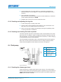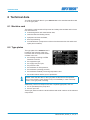
1
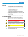
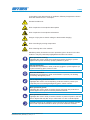
Operation manual HERKULES PFP Serial-No. ⸏⸏⸏⸏⸏⸏⸏⸏ Translation of the original operation manual HERKULES PFP_DBK_en_1402 · rs Contents Contents 1 Foreword........................................................................................................5 2 Safety..............................................................................................................6 2.1 Explanation of symbols.................................................................................6 2.2 Safety notes..................................................................................................8 2.2.1 Operating pressure.............................................................................8 2.2.2 Risks caused by the spray jet.............................................................8 2.2.3 Risks caused by electrostatic charging...............................................9 2.2.4 Explosion protection...........................................................................9 2.2.5 Risks due to the rams.......................................................................10 2.2.6 Health risks....................................................................................... 11 2.3 Information signs on the unit....................................................................... 11 2.4 Safety features............................................................................................12 2.4.1 Compressed air shut-off valves........................................................12 2.4.2 Safety valve......................................................................................13 2.4.3 Grounding wheels.............................................................................13 2.4.4 Grounding cable...............................................................................13 2.5 Operating and maintenance personnel.......................................................14 2.5.1 Unit owner’s duties...........................................................................14 2.5.2 Personnel qualification......................................................................14 2.5.3 Authorized operating personnel........................................................14 2.5.4 Personal Protective Equipment (PPE)..............................................14 2.6 Notes on warranty.......................................................................................15 2.6.1 Conversions and alterations.............................................................15 2.6.2 Spare parts.......................................................................................15 2.6.3 Accessories.......................................................................................15 2.7 Emergency procedures...............................................................................16 2.7.1 Shutting down and depressurising the unit.......................................16 2.7.2 Leakages..........................................................................................16 2.7.3 Injuries..............................................................................................16 3 Unit description...........................................................................................17 3.1 Intended use...............................................................................................17 3.2 Unit configuration........................................................................................18 4 Transportation, installation and assembly................................................20 4.1 Transportation.............................................................................................20 4.2 Installation location.....................................................................................20 4.3 Assembly....................................................................................................21 4.3.1 Open the ventilation hole..................................................................22 4.3.2 Assembling spray hose and spray gun.............................................22 Translation of the original operation manual HERKULES PFP3 HERKULES PFP_BAoDB_en_1402_B · rs Contents 4.3.3 Grounding the unit............................................................................22 4.3.4 Connecting the compressed air supply.............................................23 5 Operation......................................................................................................24 5.1 Put the unit into operation...........................................................................24 5.1.1 Performing pressure check...............................................................24 5.1.2 Flushing residues of the test medium...............................................25 5.1.3 Adjust the deicing system.................................................................26 5.1.4 Preparing the material to be applied.................................................26 5.1.5 Fill the unit with material and bleed it................................................27 5.2 Coating.......................................................................................................27 5.2.1 Adjusting the spraying pressure........................................................27 5.2.2 Hints to achieve good coating results...............................................28 5.2.3 Changing material drum...................................................................28 5.2.4 Intermediate flushing........................................................................29 5.3 Decommissioning.......................................................................................30 5.3.1 Complete flushing.............................................................................30 5.3.2 Disassembling and cleaning the fluid pump.....................................30 5.3.3 Assembling the fluid pump................................................................32 5.4 Waste disposal............................................................................................32 6 Maintenance.................................................................................................33 6.1 Regular inspections....................................................................................33 6.2 Maintenance plan.......................................................................................34 6.3 Maintenance unit........................................................................................34 6.3.1 Check the lubricant level in the fog oiler...........................................34 6.3.2 Checking and adjusting the fog oiler.................................................35 6.3.3 Checking and cleaning the water separator.....................................35 6.4 Fluid pump..................................................................................................35 6.4.1 Checking the release agent level......................................................35 6.4.2 Checking release agent for material residues..................................36 6.4.3 Replacing the seals on the follow plate............................................36 6.5 Recommended operating materials............................................................36 7 Troubleshooting...........................................................................................37 8 Technical data..............................................................................................38 8.1 Machine card..............................................................................................38 8.2 Type plates..................................................................................................38 4 Translation of the original operation manual HERKULES PFP HERKULES PFP_BAoDB_en_1402_B · rs Foreword 1 Foreword Dear Customer! We are delighted that you have decided in favour of a HERKULES PFP made by our company. This operation manual is intended for the operating and maintenance personnel. It contains all the information required to working with this unit. The owner of the unit must ensure that operators and maintenance personnel always have an operation manual at their disposal in a language that they understand! Safe and reliable operation of the unit requires further information in addition to this operation manual. You should have read and understood the guidelines and accident prevention regulations that apply in your country. In Germany the following apply: ➤➤ ZH 1/406 “Richtlinien für Flüssigkeitsstrahler” (Guidelines for Liquid Jets), published by the German “Hauptverband der Gewerblichen Berufsgenossenschaften”; ➤➤ BGR 500, Chapter 2.29 “Application of Coating Materials”; ➤➤ BGR 500, chapter 2.36 “Working with Fluid Spraying Equipment” published by the employers liability insurance association for the gas, remote heating and water management sectors. We strongly recommend adding all relevant guidelines and accident prevention instructions to this operation manual. Moreover the manufacturer’s instructions and guidelines for coating or feeder materials must be respected at all times. However, if you have any questions, please do not hesitate to contact us. Best wishes for good results with your HERKULES PFP from WIWA Wilhelm Wagner GmbH & Co. KG. Copyright © 2014 WIWA This operation manual remains the copyright of WIWA Wilhelm Wagner GmbH & Co. KG. Gewerbestr. 1-3 • 35633 Lahnau • Germany Tel.: +49 6441 609-0 • Fax.: +49 6441 609-50 • E-mail: [email protected] • Internet: www.wiwa.de This operation manual is solely intended for personnel involved in preparation, operation and servicing. It is prohibited to pass on this operation manual for reproduction, utilisation or communication of its contents, unless this has been explicitly permitted. Infringements incur an obligation to pay damage compensation. All rights reserved in the event of registration of the patented design, industrial design or registered design. This operation manual only applies in conjunction with the machine card that was given to you with the user manual for your unit. Please check that the data on the type plate match those on the machine card. Please notify us immediately if there are discrepancies, if the user manual has been incorrectly compiled or if the type plate is missing. Translation of the original operation manual HERKULES PFP5 HERKULES PFP_BAoDB_en_1402_B · rs Safety 2 Safety This unit has been designed and manufactured under due consideration of all safety-related aspects. It complies with the current standard of technology and the valid accident prevention instructions. The unit left the factory in perfect condition and guarantees a high level of technical reliability and safety. Nevertheless, there are certain risks that can arise from incorrect operation or misuse: ➤➤ to life and limb of the operator or third party, ➤➤ to the unit and other material assets of the owner, ➤➤ to the efficient working capacity of the unit. You must refrain from any working methods that could affect the safety of operating personnel and equipment. All the people that are involved in set-up, commissioning, operation, maintenance, repair and servicing of the unit must have read and understood the operation manual beforehand, especially the chapter entitled “Safety”. Your safety is at stake! We recommend to the owner of this unit to have this confirmed in writing. 2.1 Explanation of symbols Safety information warns you of potential risks of accidents and tell you the measures that are needed to prevent accidents. In WIWA operation manuals, safety information is specially highlighted and marked as follows: DANGER Indicates danger of accidents; if you ignore the safety notes, there is a high risk of severe injury resulting up to and including death! WARNING Indicates danger of accidents; if you ignore the safety notes, severe injury can result up to and including death! CAUTION Indicates danger of accidents; if you ignore the safety notes, severe injury can result! Indicates important information on correct use of the unit. Ignoring it can result in damage to the unit or in its vicinity. 6 Translation of the original operation manual HERKULES PFP HERKULES PFP_BAoDB_en_1402_B · rs Safety In the safety notes about the risk of accidents, different pictograms are shown after each hazard source – examples: General accident risk Risk of explosion from explosive atmosphere Risk of explosion from explosive substances Danger of injury due to electric voltage or electrostatic charging Risk of crushing by moving components Risk of burning due to hot surfaces Mandatory safety instructions concern protective gear to be worn in the first instance. They are particularly highlighted and marked as follows: Wear protective clothing Highlights the order to wear the prescribed protective clothing to protect against skin injuries caused by spraying material or gases. Use eye protection Indicates the requirement to wear protective goggles to protect against eye injuries caused by gases, fumes or dust. Wear ear defenders Indicates the requirement to wear ear defenders to prevent your hearing from being damaged by noise. Use a respiratory protection mask Highlights the order to use a respiratory protection mask to prevent your respiratory tract from being damaged by gases, fumes or dusts. Wear protective gloves Highlights the order to wear protective gloves with lower arm protection to protect against burn injuries caused by heated materials. Wear protective footwear Highlights the order to wear protective footwear to prevent injuries to the feet due to objects that may fall, drop or roll around or to hot or caustic liquids. Indicates references to guidelines, work instructions and operation manuals that contain important information which you must observe at all times. Translation of the original operation manual HERKULES PFP7 HERKULES PFP_BAoDB_en_1402_B · rs Safety 2.2 Safety notes Please remember that the unit works at high pressure and may cause life-threatening injuries if used inappropriately! Always observe and follow all instructions in this operation manual and in the separate operation manuals of individual unit components and/or the optionally available accessory devices. 2.2.1 Operating pressure WARNING Unit components that do not comply with the maximum permissible operating pressure can burst and cause serious injury. ➤➤ The specified maximum operating pressures must generally be complied with for all unit components. In case of varying operating pressures, the lowest value is always the one to be taken as the maximum operating pressure for the entire unit. ➤➤ Material hoses and hose assemblies must comply with the maximum operating pressure, including the required safety factor. ➤➤ Material hoses must be leak tight and free of kinks, signs of abrasion or bulges. ➤➤ Hose connections must be tight. 2.2.2 Risks caused by the spray jet WARNING The material is discharged from the spray gun under very high pressure. Due to its cutting effect the spray jet can cause severe injuries by penetrating the skin or entering into the eyes. ➤➤ Never point the spray gun at yourself, other persons or animals. ➤➤ Do not hold your fingers or hands in front of the spray gun! ➤➤ Do not reach with your hands into the spray jet. WARNING Unintentional material release from the spray gun may cause personal injury or damage to property. ➤➤ Always secure the spray gun during every work break! ➤➤ Always check that the safety mechanism on the spray gun works before each use! 8 Translation of the original operation manual HERKULES PFP HERKULES PFP_BAoDB_en_1402_B · rs Safety 2.2.3 Risks caused by electrostatic charging WARNING The high flow velocities associated with the Airless spraying method may cause electrostatic charging. Static discharges can cause fire and explosion. ➤➤ Make sure that the unit and the object to be coated are earthed correctly! ➤➤ Always use open containers! ➤➤ Never spray solvents or materials containing solvents into cone-top cans or drums with bunghole! ➤➤ Stand the containers on a grounded surface. ➤➤ When using metal containers watch out for contact between spray gun and container wall. ➤➤ Only use conductive material hoses. All original material hoses from WIWA are conductive and perfectly adapted to our equipment. WARNING If the unit is contaminated during spraying by coating material, the increasing coating thickness may cause electrostatic charging. Static discharges can cause fire and explosion. ➤➤ Clean the unit immediately outside the hazardous area from contamination by coating material. 2.2.4 Explosion protection WARNING Units that are designed without explosion protection must not be used in workshops that come under the explosion protection ordinance. Explosion-protected units meet the explosion protection requirements of Directive 94/9/EC for the explosion group, unit category and temperature class specified on the type plate or in the declaration of conformity. The operator is responsible for determining the zone allocation according to the Directive of EC 94/9/EC, Appendix II, no. 2.1-2.3 when observing the measures of the responsible inspecting authority. The operator is responsible for checking and ensuring that all technical data and markings according to ATEX correspond with the necessary requirements. Please note that several unit components have their own type plate with separate marking according to ATEX. In this case the lowest explosion protection of all attached markings applies for the entire unit. Applications where malfunctioning of the unit can lead to danger to personnel must be provided with appropriate safety measures by the operator. However, if agitators, heaters or other electrically accessories are additionally mounted, one must check the explosion protection. Plugs for heaters, agitators, etc. that do not have explosion protection, may only be plugged in outside of areas that fall under the explosion protection ordinance, even if the accessory equipment as such is explosion protected. Translation of the original operation manual HERKULES PFP9 HERKULES PFP_BAoDB_en_1402_B · rs Safety WARNING Heating up cleaning agents can cause an explosion. This may result in serious injury to persons and damage to property. ➤➤ Pay attention to the flashpoint and the ignition temperature of the cleaning agent. ➤➤ Switch off the material flow heater if you need to perform the following work: Cleaning, pressure testing, decommissioning, maintenance and repair. 2.2.5 Risks due to the rams WARNING While the rams are lifting, the moving components can crush your fingers, hands or other parts of the body. ➤➤ Do not reach between the follow plate and the material drum, the traverse and cylinder cover of the pneumatic cylinder or the clamping piece and the cylinder cover of the pneumatic cylinder. WARNING While the rams are lifting, loose clothing can get between the follow plate or the follow cover and the material drum or catch on other moving components or be pulled upwards. ➤➤ Wear tight-fitting working clothes that are not very tear-resistant, that have tight-fitting sleeves and no protruding parts. WARNING While the rams are lifting, the moving components can cause crushing or impact injuries. ➤➤ While the rams are lifting, nobody must be in the lifting area. WARNING Accidental starting of the rams can result in crushing and impact injuries. ➤➤ Each time work is interrupted, set the ram control levers to the “Stop” position. WARNING Objects placed on the rams may fall down during a stroke movement and cause injuries. ➤➤ Never place any objects on the rams! 10 Translation of the original operation manual HERKULES PFP HERKULES PFP_BAoDB_en_1402_B · rs Safety 2.2.6 Health risks Follow the safety notes and dosing information of the manufacturer and the generally applicable regulations when handling paints, solvents, oils, greases and other chemical substances. CAUTION Depending on the materials being applied solvent vapours may be generated which could cause damage to health and objects. ➤➤ Always ensure sufficient aeration and ventilation at the workplace. ➤➤ Always observe the processing instructions issued by the material manufacturers. When cleaning your skin, use only appropriate skin protection, skin cleaning and skin care products. In closed or pressurized systems dangerous chemical reactions may occur if parts made of aluminium or galvanized parts come into contact with 1.1.1 - trichloroethane, methylene chloride or other solvents containing halogenated hydrocarbons (CFC’s). If you want to process materials containing the afore mentioned substances, we recommend to consult the material manufacturer to clarify the usability of such substances. For these materials, we have available a range of rust- and acid-proof units. 2.3 Information signs on the unit Information signs attached to the unit, like safety information (see Fig. 1) refer to possible danger areas and must be strictly observed. They must not be removed from the unit. Damaged and illegible information signs must be replaced immediately. Apart from this you should also read and follow the safety notes in the operation manual. Fig. 1: Safety Information Translation of the original operation manual HERKULES PFP11 HERKULES PFP_BAoDB_en_1402_B · rs Safety 2.4 Safety features WARNING If one of the safety features is missing or not fully functional, the operating safety of the unit cannot be guaranteed! ➤➤ If you discover any faults in the safety features or other deficiencies on the unit, stop operation of the unit immediately. ➤➤ Only resume operation of the unit after the fault has been completely eliminated. Safety features must be checked with the unit depressurized: ➤➤ before initial commissioning, ➤➤ always before starting work, ➤➤ after set-up work, ➤➤ after all cleaning, servicing and repair work. The unit is equipped with the following safety features: ➤➤ Compressed air shut-off valves, ➤➤ Safety valve, ➤➤ Grounding wheels, ➤➤ Grounding cable. Check list: 55 Function of compressed air shut-off valves correct? 55 Lead seal on the safety valves still intact? 55 Safety valves externally free of damage? 55 Grounding wheel clean and free of damag? 55 Grounding cable free of damage? 55 Grounding cable connections on unit and conductor in good condition? 2.4.1 Compressed air shut-off valves The compressed air shut-off valve on the air maintenance unit (see Fig. 2) interrupts the air supply for the unit. Furthermore, the unit is equipped with a further compressed air shutoff valve for interrupting the air supply to the container ventilation. The functional principle of all compressed air shut-off valves that are installed on the unit is identical: Close Open Fig. 2: Compressed air shut-off valve ➤➤ Open set in the direction of flow ➤➤ Close set across the direction of flow After closing the air, the unit is still pressurized. This means that before carrying out maintenance and repair work, you must always carry out complete pressure release! 12 Translation of the original operation manual HERKULES PFP HERKULES PFP_BAoDB_en_1402_B · rs Safety 2.4.2 Safety valve The safety valve is installed in the air motor of the HERKULES PFP. The safety valve ensures that the max. permissible air inlet pressure is not exceeded. If the air inlet pressure exceeds the fixed limiting value, the safety valve will blow off. Fig. 3: Safety valve WARNING If the maximum permissible air inlet pressure is exceeded, unit components may burst. This may result in damage to persons and property. ➤➤ Never allow the unit to run with or without defective safety valves! ➤➤ If a safety valve needs to be replaced, you can find the corresponding order number on the machine card. ➤➤ With new safety valves, ensure that they have been set to the maximum permissible air inlet pressure of the unit (see type plate/machine card) and sealed with a lead seal. 2.4.3 Grounding wheels The two swivel rollers of the chassis are electrically conductive. They contact the unit to the floor in order to discharge static electricity. Check the grounding wheels regularly for dirt and clean them if necessary. Fig. 4: Grounding wheels 2.4.4 Grounding cable In order to prevent to prevent electrostatic charging, the unit must be grounded with the grounding cable to an electrically conductive object (see chapter 4.3.3 on page 22). If the grounding cable ist defect or lost you must order a new immediately. Translation of the original operation manual HERKULES PFP13 HERKULES PFP_BAoDB_en_1402_B · rs Safety 2.5 Operating and maintenance personnel 2.5.1 Unit owner’s duties The unit owner: ➤➤ is responsible for the training of the operating and maintenance staff, ➤➤ must instruct the operating and maintenance staff in correct handling of the unit as well as in wearing the correct work clothing and personal protective equipment, ➤➤ must make the user manual available to the operating and maintenance staff and ensure that it always remains available, ➤➤ must ensure that the operating and maintenance staff have read and understood the user manual. Only then may the unit be brought into service. 2.5.2 Personnel qualification A differentiation is made between two groups of people in dependence on their qualifications: ➤➤ Instructed operators have been verifiably instructed by the unit owner in the activities they are tasked with and the potential risks connected with them in the case of incorrect behaviour. ➤➤ Trained personnel have been instructed by the unit builder such that they are capable of carrying out maintenance and repair work on the system and recognising potential risks on their own initiative and of avoiding these risks. 2.5.3 Authorized operating personnel Activity Qualification Setup and operation Instructed operator Cleaning Instructed operator Servicing Trained personnel Repair Trained personnel Juveniles under the age of 16 are not allowed to operate this unit. 2.5.4 Personal Protective Equipment (PPE) WARNING Inside hazardous areas, static charges can result in serious accidents. ➤➤ Wear inside hazardous areas only antistatic protective clothing (overall, protective gloves and protective footwear). Wear protective clothing Always wear the protective clothing prescribed for your work environment and follow the recommendations in the safety data sheet issued by the material manufacturer. 14 Translation of the original operation manual HERKULES PFP HERKULES PFP_BAoDB_en_1402_B · rs Safety Use eye protection Indicates the requirement to wear protective goggles to protect against eye injuries caused by material splatter gases, fumes or dust. Wear ear defenders Operating personnel should be provided with suitable noise protection equipment. The unit operator is responsible for adhering to the accident prevention regulation “Noise” (BGV B3). For this reason, pay special attention to the conditions at the installation location – the noise burden, for example, will increase if the system is installed in or on hollow bodies. Wear a respiratory protection mask We strongly recommend that you wear a respiratory protection mask, even though the paint mist has been minimized in the airless spray painting method given a correct pressure setting and correct working methods. Wear protective gloves When applying heated materials you should wear protective gloves with lower arm protection, to protect you against burn injuries. Wear protective footwear Wear protective footwear to prevent injuries to the feet due to objects that may fall, drop or roll around and to prevent slipping on a slippery floor. 2.6 Notes on warranty 2.6.1 Conversions and alterations ➤➤ Unauthorized conversions or alterations should not be undertaken on safety grounds. ➤➤ Protective equipment should not be dismantled, converted or bypassed. ➤➤ The unit must only be operated within the specified limiting values and parameters. 2.6.2 Spare parts ➤➤ When carrying out maintenance and repair work, you must only use WIWA original spare parts. ➤➤ Use of spare parts which have not been manufactured or delivered by WIWA renders any warranty null and void. 2.6.3 Accessories ➤➤ Using original WIWA accessories guarantees that they are usable in our units. ➤➤ If you use third-party accessories, they must be suitable for the unit – particularly with regard to the operating pressure, the electrical connection data and the connection sizes. WIWA accepts no liability for damage or injuries resulting from the use of these parts. ➤➤ You must observe the safety regulations of the accessories. These safety regulations are found in the separate operating instructions for the accessories. Translation of the original operation manual HERKULES PFP15 HERKULES PFP_BAoDB_en_1402_B · rs Safety 2.7 Emergency procedures 2.7.1 Shutting down and depressurising the unit In an emergency, the unit must be shut down and depressurised immediately. 1. Regulate the compressed air pressure regulators for the pump and the ram fully back. 2. Close the compressed air shut-off valve on the air maintenance unit. 3. Close and lock the spray gun. 4. Hold the drain hose into a collection container and ensure that it can not slip. 5. Open the drain valve. 2.7.2 Leakages WARNING In case of leakages material can escape under very high pressure and cause serious bodily injuries and material damage. ➤➤ Immediately shut down the unit and depressurize it. ➤➤ Retighten any screw fittings and replace defective parts (only by trained personnel). ➤➤ Do not try to seal leaks on the connections and high-pressure hoses with the hand or by wrapping fabric around them. ➤➤ Do not repair material hoses! ➤➤ Check hoses and screw fittings for leaks when recommissioning the unit. 2.7.3 Injuries In the case of injuries by processing materials or solvents, always have available the manufacturer’s safety data sheet (address, phone number, material designation and material number of the supplier or manufacturer) for the attending physician. 16 Translation of the original operation manual HERKULES PFP HERKULES PFP_BAoDB_en_1402_B · rs Unit description 3 Unit description The HERKULES PFP is a coating unit for insulating layer forming flame retardants. It was designed to meet special customer requirements (material to be applied, mixing ratio, transfer quantity, etc.). The unit is used for coating steel parts in structural engineering, as weil as in the oil and gas industry. The technical data for your unit can be found in the attached machine card. 3.1 Intended use The HERKULES PFP is intended for the application of insulating layer forming flame retardants in commercial and industrial applications. Any other use is considered to be unintended. If you intend to use the unit for other purposes or with other materials and thus not for the purpose for which it is intended, you must ask WIWA for permission – otherwise the warranty will be invalidated. Intended use also includes compliance with the technical documentation and adherence to the prescribed operating, servicing and maintenance guidelines. Translation of the original operation manual HERKULES PFP17 HERKULES PFP_BAoDB_en_1402_B · rs Unit description 3.2 Unit configuration 1 10 2 11 3 12 4 13 5 14 6 15 7 8 9 Fig. 5: Front view of the HERKULES PFP No. Designation 1 Silencer 3 Overflow with ventilation hole 2 4 5 6 7 8 9 10 11 12 13 14 15 18 Air motor Twin post ram Fluid pump Connection for the spray hose Drain ball valve Drain hose Follow plate Release agent filler neck Release agent drain screw Control lever for the ram Pressure gauge for the ram Compressed air shut-off valve for the container ventilation Connection for the container ventilation Translation of the original operation manual HERKULES PFP HERKULES PFP_BAoDB_en_1402_B · rs Unit description 19 16 17 17 20 21 22 23 18 24 25 Fig. 6: Rear view of the HERKULES PFP No. Designation 16 Maintenance unit 18 Air pressure regulator for the ram 17 19 20 21 22 23 24 25 Ring screws for safe lifting with hoisting devices Air pressure regulator for the pump Deicing system Pressure gauge for the air inlet pressure Compressed air shut-off valve Compressed air connection Container ventilation with ball valve Grounding terminal with grounding cable The functional principle of all pressure regulators that are installed on the unit is identical: ➤➤ Turn clockwise to increase the pressure, ➤➤ turn anti-clockwise to reduce the pressure. Translation of the original operation manual HERKULES PFP19 HERKULES PFP_BAoDB_en_1402_B · rs Transportation, installation and assembly 4 Transportation, installation and assembly The unit left the factory in flawless condition and was appropriately packed for transportation. Check the unit on receipt for any damage in transit and for completeness. 4.1 Transportation Please follow these notes when transporting the unit: ➤➤ Ensure sufficient load bearing capacity of lifting gear and lifting tackle when loading the unit. You will find the dimensions and weights of the unit on the machine card. ➤➤ The unit must only be lifted by the lifting and lashing points provided for this purpose. ➤➤ Caution danger of tipping! Ensure even load distribution to secure the system against tipping over. ➤➤ Do not transport any other objects (e.g. material drums) while lifting or loading the unit. ➤➤ Never stand under suspended loads or inside the loading area. This poses a life hazard! ➤➤ Secure the load on the transport vehicle against slipping and falling off. If the unit was already operated, please observe the following: ➤➤ Disconnect the entire system power supply – even for short transportation distances. ➤➤ Empty the unit before transportation – fluid residues may escape during transportation despite this measure. ➤➤ Remove all loose parts (e.g. tools) from the unit. ➤➤ Assemble the parts or fittings dismantled for transport purposes before start up and in compliance with the intended use of the system. 4.2 Installation location The HERKULES PFP can be installed inside and outside spray booths. However, outdoor installation should be preferred in order to avoid contamination. WARNING If the unit is used outside during a thunderstorm, a lightning strike can cause a life-threatening situation for the operating personnel. ➤➤ Do not operate a unit out of doors during a thunderstorm! ➤➤ The unit owner must ensure that the unit is equipped with suitable lightning protection equipment. Set the unit up horizontally on a foundation that is flat, firm and vibration-free. The unit must not be tipped or on an incline. Ensure that all the operating elements and safety features are easy to reach. 20 Translation of the original operation manual HERKULES PFP HERKULES PFP_BAoDB_en_1402_B · rs Transportation, installation and assembly Safety measures at the place of installation: ➤➤ This unit requires a solid base and sufficient free space for safe operation. ➤➤ Secure the unit at its final location to protect it against unintended movement. To do this, engage the wheel brakes on the swivel rollers (see Fig. 7). ➤➤ Always keep the working area, especially all walkways and standing areas, clean and tidy. Immediately remove any spilled Fig. 7: Wheel brake material and solvents immediately. ➤➤ Always ensure adequate ventilation at the work place to avoid damage to health and material objects. At least a 5-fold air exchange must be ensured. ➤➤ Always observe the processing instructions issued by the material manufacturers. ➤➤ Even though there are no legal directives for low-mist Airless spraying methods, all hazardous solvent vapours and paint particles should be extracted. ➤➤ Protect objects adjacent to the spraying object against possible damage caused by the material mist. 4.3 Assembly WARNING If assembly work is carried out by people who have not been trained for this work, you endanger yourself and other people and impair the safety and reliability of the unit. ➤➤ Electrical components must only be mounted by trained time-served electricians – with all the other components, e.g. the spray hose and the spray gun being assembled by trained personnel only. The spray gun material hose and the spray gun were separately packed for transport. Please assemble these parts before using the unit for the first time. WARNING Components that do not comply with the maximum permissible operating pressure may burst und cause severe injuries. ➤➤ Before assembling, check the maximum permissible pressure for the separately packaged components and accessories. lt must be higher than or equal to the maximum operating pressure of the unit as specified on the type plate. ➤➤ Compare the maximum operating pressure of the safety valves with the specifications in the machine card or on the type plate. These data must match! Translation of the original operation manual HERKULES PFP21 HERKULES PFP_BAoDB_en_1402_B · rs Transportation, installation and assembly 4.3.1 Open the ventilation hole When being used for the first time, the sticker with the text „remove before use“ and the sealing plug is to be removed from the ventilation hole. The ventilation hole is located in the elbow with the openeing facing downward (overflow). Fig. 8: Ventilation hole 4.3.2 Assembling spray hose and spray gun Fit the spray hose to the material outlet of the fluid pump (see Fig. 9). Connect the spray hose to the spray gun as described in the operating manual for the spray gun. Fig. 9: Connection for the spray hose 4.3.3 Grounding the unit WARNING The high flow velocities associated with the Airless spraying method may cause electrostatic charging. Static discharges can cause fire and explosion. ➤➤ Make sure that the unit and the object to be coated are properly grounded! The grounding cables for all components for which grounding is required are merged into the grounding terminal. In order to ground the unit, connect the main grounding cable first to clamp 1 of the grounding terminal and then to an electrically conductive object outside the hazardous area. Fig. 10: Grounding terminal 22 Translation of the original operation manual HERKULES PFP HERKULES PFP_BAoDB_en_1402_B · rs Transportation, installation and assembly 4.3.4 Connecting the compressed air supply The compressor capacity must match the air requirements of the unit and the diameters of the air supply hoses must match the connections such that an adequate air supply is ensured. Operation with contaminated or moist compressed air causes damage to the unit’s pneumatic system. ➤➤ Use only dry dust- and oil-free air! 1. Make sure that the compressed air shut-off valves are closed and all air pressure regulators have been fully regulated back. 2. Connect the compressed air supply hose to the air maintenance unit. Fig. 11: Compressed air connection Translation of the original operation manual HERKULES PFP23 HERKULES PFP_BAoDB_en_1402_B · rs Operation 5 Operation Before starting work, check: 55 Are all the safety features present and fully functional (see chapter 2.4 on page 12)? 55 Are all unit components tight? If required, tighten up these connections. 55 Is there enough lubricant in the fog oiler’s oil container (see chapter 6.3.1 on page 34)? 55 Is there enough release agent in the pump? WARNING If material pumps run dry, the generated friction heat can cause fire or an explosion. ➤➤ Always make sure that the material drums do not run dry during operation. ➤➤ However, should this happen, stop the pump immediately and feed material. 5.1 Put the unit into operation Prerequisites: ➤➤ The unit must have been set up correctly and completely assembled. ➤➤ Do not start commissioning the unit unless you have the specified protective equipment. For details, refer to chapter 2.5.4 on page 14. ➤➤ The material to be processed must be available in sufficient quantity. In addition, you will need one suitable collecting vessel for excess material. This container is not included in the scope of delivery. Overview of the work sequence for commissioning: 1. Perform pressure check 2. Flush residues of the test medium (only during initial commissioning) 3. Adjust the deicing system 4. Prepare the material to be applied 5. Fill the unit with material and bleed it 5.1.1 Performing pressure check Check list before pressure check: 55 Have all compressed air shut-off valves been closed? 55 Have all air pressure regulators been regulated completely back? 55 Is the control levers of the ram in “Stop” position? 55 Is the spray gun locked? 1. Open the compressed air shut-off valve on the air maintenance unit. 2. Increase the air inlet pressure with the air pressure regulator for the pump slowly to the maximum permissible value given on the type plate. 3. Check that all parts of the machine are tight. 24 Translation of the original operation manual HERKULES PFP HERKULES PFP_BAoDB_en_1402_B · rs Operation 4. Increase the air inlet pressure for a short time by about 10% above the maximum permissible value. The safety valve must blow off. 5. Regulate the air pressure regulator for the pump fully back. 5.1.2 Flushing residues of the test medium After assembly, this unit was factory tested for flawless function by means of a test substance. The unit must be flushed with a flushing agent during initial commissioning so that the material to be sprayed is not affected by the test medium. 1. Remove the nozzle from the spray gun. 2. Unscrew the follow plate. Take care that the seal between the follow plate and the pump is not lost. 3. Regulate a pressure of 1.5 - 2 bar on the air pressure regulator for the ram. 4. Set the ram control lever to position “Up”, to move the ram with the pump up. Fig. 12: Ram control lever 5. Once there is sufficient space under the pump for the flushing agent container, set the ram control lever to “Stop” (middle position as shown in Fig. 12). 6. Place a drum with with 10-15 l flushing agent below the pump. 7. Set the ram control lever to position “Down” an move the ram down until the suction of the pump immersed into the flushing agent. 8. Hold the drain hose into the collecting vessel (see Fig. 13). 9. Open the drain ball valve. Fig. 13: Drain hose 10.Regulate the air inlet pressure on the air pressure regulator for the pump so that the pump runs slowly. 11.Allow the flushing agent, soiled with the test medium, to run out of the drain hose into the collecting vessel for at least 10 seconds. 12.Close the drain ball valve. 13.Hold the spray gun into the collecting vessel. 14.Unlock the spray gun and spray for a minimum of 10 seconds against the inner wall of the container. We recommend a cleaning period of approx. one minute for a good cleaning result. WARNING Heating up flushing agents can cause an explosion. This may result in serious injury to persons and damage to property. ➤➤ In order to avoid the danger of explosion caused by heating up the flushing agent, it must not be pumped longer than 5 minutes. Translation of the original operation manual HERKULES PFP25 HERKULES PFP_BAoDB_en_1402_B · rs Operation 15.Close and lock the spray gun. 16.Set the ram control lever to position “Up”, to move the ram with the pump up. 17.Once there is sufficient space for removing the flushing agent container, set the ram control lever to position “Stop”. 18.Remove the flushing agent container. 19.Screw on the follow plate with seal. 5.1.3 Adjust the deicing system 1. Turn the adjusting screw for the deicing system at the air motor slowly counterclockwise – minimum one and maximum three turns. Exact settings should be made individually and as required because the degree of icing depends on various factors, such as e.g. pressure, number of double strokes per minute, air humidity, ambient temperature. Fig. 14: Adjusting screw for the deicing system When interrupting work or in case of decommissioning the adjusting screw of the deicing system remains open. 5.1.4 Preparing the material to be applied Observe the technical notes of the respective material manufacturer. 1. If necessary, heat up the containers of the A and B component to the processing temperature recommended by the material manufacturer. 2. If permissable for the material used, mix some solvents into the A component using the hand mixer. 3. Mix the B component into the A component using the hand mixer. 4. Clean the hand mixer with solvent and leave it standing in the container with solvent. This work is best done by a second person so that there is no loss of working time for the mixed material. Fig. 15: Mixing of material 26 Translation of the original operation manual HERKULES PFP HERKULES PFP_BAoDB_en_1402_B · rs Operation 5.1.5 Fill the unit with material and bleed it 1. Place the material drum centered below the follow plate. 2. Regulate a pressure of 2 - 3 bar on the air pressure regulator for the ram. 3. Open the ventilation ball valve at the follow plate (see Fig. 16). 4. Set the ram control lever to position “Down” to move the ram down. 5. Once all air has escaped from the material container, close the ventilation ball valve on the follow plate. 6. Hold the drain hose into the collecting vessel. 7. Open the drain ball valve. Fig. 16: Ventilation ball valve 8. Regulate the air inlet pressure on the air pressure regulator for the pump so that the pump runs slowly. 9. Close the drain valve again as soon as the processing material exits the drain hose. 10.Hold the spray gun into the collecting vessel. 11.Unlock the spray gun and operate it until the processing material exits the spray gun. 12.Close and lock the spray gun. The unit is ready for operation. You can start coating. 5.2 Coating Prior to coating, the unit must be commissioned. 1. Clean the spray gun outlet. 2. Screw the nozzle back into the spray gun. 3. Adjust the optimal spraying pressure using the air pressure regulator for the pump (see chapter 5.2.1). 5.2.1 Adjusting the spraying pressure Please observe the following information when adjusting the spraying pressure: ➤➤ Optimal spraying pressure is indicated by a uniform application of material with fading out peripheral zones. ➤➤ Operate the unit only with an air pressure as high as necessary, to achieve a good atomization at the recommended spraying distance of approx. 30 - 40 cm or 12 - 16 inches. ➤➤ Too high spraying pressure causes increased material consumption and paint mist. ➤➤ Too low spraying pressure results in the appearance of stripes and differences in the coating thickness. 30-40 cm Fig. 17: Spraying distance Translation of the original operation manual HERKULES PFP27 HERKULES PFP_BAoDB_en_1402_B · rs Operation 5.2.2 Hints to achieve good coating results ➤➤ Hold the spray gun at right angles (90°) to the area to be coated. If the spray gun is held under a different angle, the coating becomes irregular and blotchy (see Fig. 18). ➤➤ Ensure an even speed and move the spray gun parallel to the area to be coated. Waving the spray gun causes irregular coating (see Fig. 19). ➤➤ Move the spray gun with your arm and not with your wrist. ➤➤ Already move the spray gun before pulling the trigger. In this way, you will achieve perfect, soft and smooth overlapping of the spray jet and avoid excessively thick application of material at the beginning of the spraying process. ➤➤ Release the trigger before stopping the movement. ➤➤ Replace the spray nozzles before these are worn. right ng wro Fig. 18: Spray angle thin layer thick thin layer layer Area to be coated wrong Fig. 19: Do not wave! Worn nozzles cause higher material consumption and have a negative effect on the quality of coating. 5.2.3 Changing material drum Exchange the material drum when it is empty. After processing of 6 material drums, the pump must be flushed intermediately in order to remove material deposits from the unit and prevent a blockage of the pump (see chapter 5.2.4). 1. Regulate the air inlet pressure of the pump completely back. 2. Set the ram control lever to “Stop”. 3. Open the compressed air shut-off valve for the container ventilation. 4. Set the ram control lever to position “Up”, to move the ram up. 5. Once the sealing lip of the follow plate reaches the top of the material drum, close the compressed air shut-off valve for the container ventilation. 6. Once there is sufficient space for removing the material drum, set the ram control lever to position “Stop”. 7. Remove the old material drum. 8. Place the new material drum centered below the follow plate. 9. Open the ventilation ball valve at the follow plate. 10.Set the ram control lever to position “Down” to move the ram down. 11.Once all air has escaped from the material container, close the ventilation ball valve on the follow plate. 12.Adjust the optimal spraying pressure using the air pressure regulator for the pump. 28 Translation of the original operation manual HERKULES PFP HERKULES PFP_BAoDB_en_1402_B · rs Operation 5.2.4 Intermediate flushing 1. Regulate the air inlet pressure of the pump completely back. 2. Set the ram control lever to “Stop”. 3. Open the compressed air shut-off valve for the container ventilation. 4. Set the ram control lever to position “Up”, to move the ram up. 5. Once the sealing lip of the follow plate reaches the top of the material drum, close the compressed air shut-off valve for the container ventilation. 6. Once there is sufficient space for removing the material drum, set the ram control lever to position “Stop”. 7. Remove the material drum. 8. Unscrew the follow plate. Take care that the seal between the follow plate and the pump is not lost. 9. Clean the follow plate thoroughly. The black rubber seal is not solvent resistant. Do not soak in solvent, but only wipe the seal clean. 10.Place a drum with with 10-15 l flushing agent below the pump. 11.Set the ram control lever to position “Down” an move the ram down until the suction of the pump immersed into the flushing agent. 12.Hold the drain hose into the collecting vessel. 13.Open the drain ball valve. 14.Regulate the air inlet pressure on the air pressure regulator for the pump so that the pump runs slowly. Do not trigger the spray gun during the intermediate flushing to prevent mixing of the solvent with the material in the spray hose. 15.Allow the pump to run until the solvent runs out of the drain hose. 16.Hold the drain hose into the flushing agent drum and allow the unit to run for 2-3 minutes, so that all remaining material is flushed out of the unit. 17.Move the ram up. 18.Remove the flushing agent drum. 19.Screw on the follow plate with seal. 20.Place the (new) material container under the pump and fill the pump with material. Collect the remaining solvent that exits the drain hose, in a container for waste material. 21.Close the drain valve again as soon as the processing material exits the drain hose. 22.Proceed with coating work. Translation of the original operation manual HERKULES PFP29 HERKULES PFP_BAoDB_en_1402_B · rs Operation 5.3 Decommissioning Overview of the work sequence for decommissioning: 1. Flush the unit completely (see chapter 5.3.1 on page 30) 2. Shut down and depressurise the unit (see chapter 2.7.1 on page 16) 3. Disassemble and clean the fluid pump (see chapter 5.3.2 on page 30) 4. Assemble the fluid pump (see chapter 5.3.3 on page 32) 5.3.1 Complete flushing If working with dual component materials, the pot life must be observed. The unit must be flushed and completely cleaned with the appropriate solvent within the pot life given by the material manufacturer. 1. Flush the pump at first through the drain hose, as described in chapter 5.2.4 on page 29 (work steps 1-16). 2. Lock the spray gun and remove the nozzle. 3. Clean the nozzle by hand. 4. Hold the spray gun into the collecting vessel. 5. Trigger the spray gun until clean flushing agent appears. 6. Hold the spray gun into the flushing agent drum and allow the pump to circulate flushing agent via the spray gun for 2-3 min. 7. Exchange the flushing agent drum for a clean one with new flushing agent and repeat the complete flushing procedure (via the drain hose and the spray gun). 5.3.2 Disassembling and cleaning the fluid pump WARNING Despite releasing the pressure, material congestion or agglomeration of material may mean that there are residual pressures still present. These may suddenly release during disassembly work and can result in serious injuries. ➤➤ You must be particularly careful during disassembly work! ➤➤ When disconnecting material hoses you should cover the screw fitting with a cloth to catch any escaping material sprays. CAUTION The parts of the fluid pump are heavy. At best, work In pairs and position a soft mat to catch falling parts. 30 Translation of the original operation manual HERKULES PFP HERKULES PFP_BAoDB_en_1402_B · rs Operation 1. Unscrew the material outlet and the drain hose. 2. Drain the release agent (Mesamoll) into a catch container. 3. Unscrew the nuts on the 6 threaded bolts (see Fig. 20). 4. Pry the pressure cylinder from the spring housing using a pry bar or screwdriver (see Fig. 21). Fig. 20: Unscrew the nuts on the threaded bolts Fig. 21: Pry the pressure cylinder from the spring housing Fig. 22: Pry the spring housing from the HP-head 5. Pry the spring housing from the HP-head (see Fig. 22). 6. Lower the dual piston to its lowest position using brief increases and decreases in the air pressure. 7. Pry the intermediate body from the air motor. It will be caught by the dual piston. 8. Unscrew 2-3 of the threaded bolts to allow removal of the HP-head and the dual piston from the coupling (see Fig. 23). 9. Clean the piston, piston valve, bottom valve, pressure cylinder, intermediate body, spring housing, threaded bolts and nuts thoroughly using solvent. Fig. 23: Remove the HP-head and the dual piston from the coupling Take care that the dual piston, packings, seals and threads are not damaged. Translation of the original operation manual HERKULES PFP31 HERKULES PFP_BAoDB_en_1402_B · rs Operation 5.3.3 Assembling the fluid pump The drawing in the spare parts list can be very helpful for assembling the fluid pump (Order No. 0641416). 1. Place the counter ring on the dual piston (note correct direction!), followed by the intermediate body (don’t forget the seal!). intermediate body dual piston Fig. 24: Counter ring 2. Push the dual piston sidewards into the coupling on the air motor. 3. Screw in the threaded bolts. 4. Place the counter ring onto the lower packing, followed by the spring. 5. Place the spring housing (material outlet towards the top) loosely over the spring onto the pressure cylinder. 6. Place the 2nd spring in the top of the spring housing. 7. Lower the ram carefully until the dual piston slides through the spring housing into the pressure cylinder. All threaded bolts must pass sufficiently through the connecting ring to avoid damaging the threads. 8. Place the washers on the bolts and screw on the nuts. 9. Tighten the nuts step-wise in a crossing pattern to pull the pump evenly together. Torque finally to 110 Nm and add the lock nuts. 10.Screw on the follow plate with seal. 5.4 Waste disposal At the end of use, you must shut down and dismantle the unit and dispose of it in accordance with legal regulations. ➤➤ Clean the unit thoroughly of all material residues. ➤➤ Dismantle the unit and separate all materials – dispose of metal together with scrap metal; plastic parts can be disposed of as domestic waste. ➤➤ Rests of spraying material, cleaning agent, oils, greases and other chemical substances must be collected in accordance with statutory provisions concerning recycling and waste disposal. The official local waste water laws are valid. 32 Translation of the original operation manual HERKULES PFP HERKULES PFP_BAoDB_en_1402_B · rs Maintenance 6 Maintenance WARNING If maintenance and repair work is carried out by persons who have not been trained for this work you endanger yourself, other persons and impair the safety and reliability of the unit. ➤➤ Maintenance and repair work on electrical components must only be carried out by trained electricians – any other maintenance and repair work must be performed by WIWA customer service or by specially trained personnel. Before maintenance and repair work: 1. Cut off the compressed air supply. 2. Depressurize the unit completely. WARNING Despite releasing the pressure, material congestion or agglomeration of material may mean that there are residual pressures still present. These may suddenly release during disassembly work and can result in serious injuries. ➤➤ You must be particularly careful during disassembly work! ➤➤ When disconnecting material hoses you should cover the screw fitting with a cloth to catch any escaping material sprays. After completing maintenance and repair work, check the function of all the safety features and that the unit is functioning correctly. 6.1 Regular inspections According to the accident prevention instructions for “Work with fluid spraying equipment” BGV D15, the unit must be inspected and serviced regularly by a specialist (WIWA customer service). The unit must be inspected: ➤➤ before initial commissioning, ➤➤ after the modification or repair of parts of the system, which could affect safety, ➤➤ after work breaks longer than 6 months, ➤➤ but at least every 12 months. For decommissioned units, the inspection can be postponed until the next commissioning. The inspection results must be recorded in writing and kept until the next inspection. The inspection report or a copy of it must be available at the place of use of the unit. Translation of the original operation manual HERKULES PFP33 HERKULES PFP_BAoDB_en_1402_B · rs Maintenance 6.2 Maintenance plan The information in the maintenance plan is a recommendation. The intervals may vary in dependence on the condition of materials used and outer influences. Interval Activity before each start-up Check the release agent level in the fluid pump before each start-up 1 x per week 1 x per week every 50 operating hours Check the lubricant level in the fog oiler Check and adjust the fog oiler Check and clean the water separator Check release agent of the fluid pump for material residues 6.3 Maintenance unit 1 2 3 No. Designation 1 Fog oiler adjusting screw 3 Oil filler plug 2 4 4 5 6 5 6 7 8 Inspection glass Locking slide Oil tank Water separator Drain valve Drain hose 7 8 Fig. 25: Maintenance unit 6.3.1 Check the lubricant level in the fog oiler The unit must only be commissioned if the oil reservoir of the fog oiler contains enough oil. In case of high humidity, use antifreeze for lubrication to avoid icing of the air motor. Check the lubricant level every day as follows: 1. Press up the locking slide on the oil reservoir and unscrew the oil reservoir by turning it anti-clockwise. Take care of the O-ring that seals the oil reservoir. It may be displaced or even fall out at dismantling. 2. Check whether the O-ring fits correctly – if necessary, fit it correctly. 34 Translation of the original operation manual HERKULES PFP HERKULES PFP_BAoDB_en_1402_B · rs Maintenance 3. Check whether there is enough lubricant – when filled completely, the lubricant reaches to a point approx. 2 cm below the upper edge of the oil reservoir. 4. Top up lubricant, if necessary. We recommend using pneumatic oil (order number 0632579) or antifreeze (order number 0631387) from WIWA. 5. Reattach the oil reservoir to the air maintenance unit. 6.3.2 Checking and adjusting the fog oiler 1. Let the main pump run slowly under load. 2. Check in the fog oiler inspection glass whether 1 drop of lubricant is fed after each 10 to 15 double strokes of the air motor. 3. If this is not the case, adjust the metering by turning the regulating screw on the fog oiler with a screwdriver. 6.3.3 Checking and cleaning the water separator The water separator prevents condensation water and dirt particles from entering into the unit. In addition, a filter is installed in the water separator, which filters out particles > 40 μ from the compressed air. Therefore, no static charging of the pneumatic hoses is to be expected. The accumulated condensation water is automatically drained off through the drain valve. For this purpose hold the hose into an empty collecting vessel. Check the bowl regularly for dirt residues and clean it as required. 6.4 Fluid pump 1 No. Designation 1 2 3 Release agent filler pipe Inspection glass Release agent drain screw 2 3 Fig. 26: Fluid pump 6.4.1 Checking the release agent level Check the amount of release agent before every start-up. The release agent level must be at least half the inspection glass. If required, top up the amount of release agent through the filler pipe. We recommend using release agent from WIWA (order number 0163333). Translation of the original operation manual HERKULES PFP35 HERKULES PFP_BAoDB_en_1402_B · rs Maintenance 6.4.2 Checking release agent for material residues In order to check the release agent for material residues you must drain off a small amount of release agent from the drain screw. If the release agent is found to be contaminated with material residues, you must assume that the packing of the fluid pump is worn. In this case, have the pump packing replaced as soon as possible by WIWA customer service or by specially trained personnel. After the examination, top up the amount of fresh release agent through the filler pipe. 6.4.3 Replacing the seals on the follow plate You must replace seals on the follow plate when they are worn. You find the order numbers of the seals in the spare parts list. No. Designation 1 Fastening screws 3 Clamping ring 2 Seals 1 2 1 1 1 1 3 Fig. 27: Seals on the follow plate 1. Loosen all screws which fasten the seals and the clamping ring on the follow plate. 2. Take off the clamping ring and the old seals. 3. Slightly wet the first thread pitches of the fastening screws with a screw retention agent. 4. Turn the clamping ring with the new seals on to the follow plate. 6.5 Recommended operating materials Only user original operating materials from WIWA: Operating materials WIWA order number Release agent for isocyanate (0.5 l)¹ 0640651 Release agent (0.5 l)¹ Anti-freeze agent (0.5 l) ² Pneumatic oil (0.5 l) ² Retention agent (50 ml)³ 0631387 0632579 Lubricant (acid-free grease, 0.4kg)² Lubricant for stainless steel² 0163333 0000015 0000025 0000233 ¹Plasticizer to fill into the release agent cups of the main pump and the feed pumps ² for air maintenance unit ³Materials required for maintenance and repair work (see information in spare parts lists) The release agent and the pneumatic oil are available in large containers on request. 36 Translation of the original operation manual HERKULES PFP HERKULES PFP_BAoDB_en_1402_B · rs Troubleshooting 7 Troubleshooting Fault Possible cause/s Remedy The pump does not cycle whether the spray gun is triggered or the drain valve is opened. 1. The compressed air shut-off valve is closed. 2. The air motor is defect. ÖÖ Open the compressed air shutoff valve. ÖÖ Repair the air motor – contact customer service if necessary. Pump runs but no material is encouraged. 1. Bottom valve ball does not rise (stuck). ÖÖ Hit the bottom valve lightly from the side (hammer) – if that does not help, press on the ball from below using a peg or screwdriver until loose. ÖÖ Remove the bottom valve and clean the ball and seat thoroughly. 2. Bottom valve does not close. Pump cycles but does not stop when 1. Packing and/or valve worn. the spray gun is closed. ÖÖ Replace parts. Pump cycles evenly but the required operating pressure can not be reached. 1. Air supply / pressure is too low. ÖÖ Increase the inbound air pressure with the regulator and check the diameter of the inbound air hose. ÖÖ Use a smaller spray nozzle. ÖÖ Replace the spray nozzle. ÖÖ If possible, reduce the inbound air pressure. Fill the oiler with anti-freeze (Glysantine) and adjust it. Pump cycles unevenly (different stroke speeds on the upward and downward strokes) and the required spray pressure can not be reached. 1. The viscosity of the coating is too high (suction loss). 2. Bottom valve leaks (pump only stops on the upwards stroke when the spray gun is closed). 3. Piston valve leaks (pump only stops on the downwards stroke when the spray gun is closed). 4. Upper or lower packings leak (wear). ÖÖ Dilute or warm up the coating material. ÖÖ Remove the bottom valve and clean the ball and seat thoroughly. 1. Packings are worn. ÖÖ Replace packings. Note: Do not close or block the ventilation hole! Coating material spills out of the air motor anti-vaccum hole. 2. Spray nozzle is too big. 3. Spray nozzle is worn 4. Air motor is frozen (runs too slow). ÖÖ Clean the ball and seat in the dual piston and replace if necessary. ÖÖ Replace packings. Translation of the original operation manual HERKULES PFP37 HERKULES PFP_BAoDB_en_1402_B · rs Technical data 8 Technical data You find the technical data for your HERKULES PFP in the attached machine card or on the type plate. 8.1 Machine card The machine card contains all important and safety relevant data and information about the unit: ➤➤ exact designation and manufacturer data, ➤➤ technical data and limiting values, ➤➤ equipment and test certificate, ➤➤ data of purchasing, ➤➤ unit identification (components of the unit and accessories with article and spare parts numbers). 8.2 Type plates The type plate of the HERKULES PFP is located on the traverse of the ram. It contains the most important technical data of the unit: ➤➤ the marking according to ATEX Directive 94 / 9 / EC, ➤➤ the equipment type, ➤➤ the supply rate per cycle, Fig. 28: Example of a type plate ➤➤ the pressure ratio, ➤➤ the maximum air inlet pressure, ➤➤ the maximum operating pressure, ➤➤ the maximum material processing temperature and ➤➤ the serial number and the year of production. Please check that the data on the type plate are identical to the specifications on the machine card. Please notify us immediately in case of discrepancies or if a type plate is missing. Additionally, some unit components have a separate type plate, such as: ➤➤ the air operated piston pump and ➤➤ the twin post ram. These type plates contain the technical data and serial numbers of the affected components. 38 Translation of the original operation manual HERKULES PFP HERKULES PFP_BAoDB_en_1402_B · rs Translation of the original operation manual HERKULES PFP39 HERKULES PFP_BAoDB_en_1402_B · rs WIWA Service +49 (0)6441 609 140 Headquarters and production WIWA worldwide field service WIWA Wilhelm Wagner GmbH & Co. KG Gewerbestr. 1 - 3 35633 Lahnau, Germany Wolfgang Pucken Sales Director Northern Germany from the river Main, Israel, Hungary, Romania, Turkey, Poland, Malta, India, Pakistan, Africa, Morocco Phone: +49 6441 609-0 Fax: +49 6441 609-50 E-Mail: [email protected] Homepage: www.wiwa.de WIWA Partnership USA WIWA LP 107 N. Main St. P.O. Box 398, Alger, OH 45812 Phone: +1 (419) 757-0141 Fax: +1 (419) 549-5173 Toll Free: +1(855) 757-0141 E-Mail: [email protected] Homepage: www.wiwalp.com WIWA Subsidiary China WIWA (Taicang) Co., Ltd. Building A of Huaxin Industrial Park No.11 East Qingdao Road, Taicang City Jiangsu Province 215400, P.R.China Phone: +86 512-5354 8858 Fax: +86 512-5354 8859 E-Mail: [email protected] Homepage: www.wiwa-china.com WIWA Middle East General Trading LLC Mohd Farhan Khan Jebel Ali Industrial 1, Dubai, UAE Phone: +9714 884 8220 E-Mail: [email protected] Frankenstraße 37 53359 Rheinbach-Oberdrees, Germany Mobil: +49 173 5432559 Phone: +49 2226 12708 Fax: +49 2226 13973 Robert Jansen Senior Sales Director Finland, Sweden, Norway, Denmark, Great Britain, Southern Ireland, Scotland, England, Holland, Belgium, France, Spain, Portugal, Italy, Croatia, Greece, Czech Republic, Slovakia, Slovenia, Luxembourg, Bulgaria, Egypt, Libya, United Arab Emirates (Oman, Dubai, Abu Dhabi, Qatar, Bahrain), Kuwait, Saudi Arabia, Iran, Iraq, Cyprus, Iceland, Syria, Lebanon Support of WIWA sales directors, representatives and distributors in: South America (except Cuba and Mexico), South East Asia, Japan, South Korea, Australia and New Zealand. Hoekstraat 57 3751 AL Spakenburg, The Netherlands Mobil: +31 6 18 88 40 97 Phone: +31 3 34 94 69 81 Fax: +31 3 34 94 75 83 E-Mail: [email protected] Otto Dietrich Sales Director Russia, Ukraine, Belarus, Moldavia, Baltic States (Lithuania, Latvia, Estonia) Caucasian countries (Armenia, Azerbaijan, Georgia), Asian countries (Kazakhstan, Uzbekistan, Turkmenistan, Kyrgyzstan, Tajikistan) Lindenhof 6 56154 Boppard, Germany Mobil: +49 160 1574385 Phone: +49 6742 899336 Fax: +49 6742 899337 E-Mail: [email protected] Michel Laksander Technical Sales Director France 2 Bis rue de léglise F-02240 Brissy Hamegicourt, France Phone: +33 32 36 21 120 Mobil: +33 63 70 19 297 E-Mail: [email protected] JK Tan Sales Director Korea, Japan, Australia, South East Asia Mobil: +6012 223 7706 Phone./Fax: +603 8024 7706 E-Mail: [email protected] WWW.WIWA.DE