1
INSPIRING INNOVATIONS
RAD 24-Volt Solar
Interface Systems (SIS)
User Manual
For 40-, 60-, 80-, and 100-watt Systems
RAD-SIS-24 Solar Interface Systems
User Manual
ii
INSPIRING INNOVATIONS
RAD 24-Volt Solar
Interface Systems (SIS)
User Manual
Provides 40, 60, 80 or 100 watts of
solar power for wireless products:
•
•
•
•
Rev B • Issued: June 2007
RAD-SOL-SET-24-40 (40-watt)
RAD-SOL-SET-24-60 (60-watt)
RAD-SOL-SET-24-80 (80-watt)
RAD-SOL-SET-24-100 (100-watt)
1984B
iii
RAD-SIS-24 Solar Interface Systems
User Manual
This Manual Contains Information on the
Phoenix Contact RAD-SOL-SET-24
Solar Interface Systems (SIS)
The information given herein is based on data believed to be reliable, but Phoenix
Contact Inc. makes no warranties expressed or implied as to its accuracy and
assumes no liability arising out of its use by others. This publication is not intended
to be taken as a license to operate under, or recommendation to infringe upon, any
patents.
iv
RAD-SIS-24 Solar Interface Systems
User Manual - Table of Contents
Table of Contents
SECTION 1
Introduction
1.1
1.2
1.3
1.4
1.5
1.6
1.7
1.8
General ...................................................................................................................... 1-1
Safety ........................................................................................................................ 1-1
About this Manual ...................................................................................................... 1-1
Current Documentation on the Internet ...................................................................... 1-2
Product Description ................................................................................................... 1-2
A. Components and Assemblies ............................................................................... 1-2
System Topology ........................................................................................................ 1-2
System Power Flow ................................................................................................... 1-2
Unpacking and Inspection .......................................................................................... 1-5
SECTION 2
Technical Data
2.1
2.2
2.3
General ...................................................................................................................... 2-1
Dimensions – Solar Modules ..................................................................................... 2-4
Dimensions – SIS Enclosure ..................................................................................... 2-5
SECTION 3
SIS Location Considerations
3.1
3.2
3.3
3.4
Solar Insolation Values Worldwide ............................................................................. 3-1
Checking Sun Path for Obstructions .......................................................................... 3-1
Solar Module Orientation ........................................................................................... 3-3
Solar Module Tilt Angle .............................................................................................. 3-4
SECTION 4
Installation Procedures
4.1
4.2
4.3
4.4
4.5
4.6
4.7
4.8
General ...................................................................................................................... 4-2
Safety Precautions ..................................................................................................... 4-2
Tools and Equipment ................................................................................................. 4-2
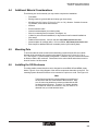
Additional Material Considerations ............................................................................. 4-3
Mounting Pole ............................................................................................................ 4-3
Installing the SIS Enclosure ....................................................................................... 4-3
System Grounding ..................................................................................................... 4-6
Removing Fuses from Electronics Panel .................................................................... 4-8
v
RAD-SIS-24 Solar Interface Systems
User Manual - Table of Contents
Table of Contents
4.9
4.10
4.11
4.12
Installing Coax Cable Surge Protector ....................................................................... 4-9
Installing Radio and Antenna Adapter ...................................................................... 4-10
Installing the Solar Modules ..................................................................................... 4-11
Wiring the Enclosure ................................................................................................ 4-14
4.12.1 Enclosure Wiring ......................................................................................... 4-14
4.12.2 Wiring the Solar Module Junction Box ......................................................... 4-18
4.12.3 Grounding the Solar Module ....................................................................... 4-20
4.13. Installing the Antenna .............................................................................................. 4-21
4.14 Installing Flexible Conduit Mounting Brackets .......................................................... 4-21
4.15 Installing the Battery ................................................................................................ 4-21
4.16 Final Checkout ......................................................................................................... 4-24
SECTION 5
Start-up & Shutdown Procedures
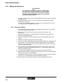
5.1
5.2
Start-Up ..................................................................................................................... 5-1
Shutdown ................................................................................................................... 5-2
SECTION 6
Charge Controller
6.1
6.2
6.3
6.4
6.5
6.6
6.7
vi
General ...................................................................................................................... 6-1
General Safety Precautions ....................................................................................... 6-2
6.2.1 Charge Controller .......................................................................................... 6-2
6.2.2 Batteries ........................................................................................................ 6-2
Connecting the Charge Controller .............................................................................. 6-2
Indication Elements .................................................................................................... 6-4
6.4.1 Green LED .................................................................................................... 6-4
6.4.2 Red LED ....................................................................................................... 6-4
Operation ................................................................................................................... 6-4
Errors ......................................................................................................................... 6-4
6.6.1 Battery Not Charging .................................................................................... 6-5
6.6.2 Battery Voltage is Too High ........................................................................... 6-6
6.6.3 Operating Error of the Load .......................................................................... 6-6
6.6.4 System Goes Into Low Voltage Disconnect (LVD) State Too Often ................ 6-7
Solar Charging System .............................................................................................. 6-7
6.7.1 Test the Solar Module – Open Circuit Voltage ............................................... 6-7
6.7.2 Test the Solar Module – Short Circuit Current ............................................... 6-8
RAD-SIS-24 Solar Interface Systems
User Manual - Table of Contents
Table of Contents
SECTION 7
Ordering Data
7.1
General ...................................................................................................................... 7-1
SECTION 8
Warranty/Repair Information
8.1
Solar Interface System (SIS) Limited Warranty .......................................................... 8-1
vii
RAD-SIS-24 Solar Interface Systems
User Manual - Table of Contents
viii
RAD-SIS-24 Solar Interface Systems
Section 1 - Introduction
1
SECTION
Introduction
Section 1 Contents
1.1
1.2
1.3
1.4
1.5
1.6
1.7
1.8
1.1
General .................................................................................................................... 1-1
Safety ...................................................................................................................... 1-1
About this Manual .................................................................................................... 1-1
Current Documentation on the Internet .................................................................... 1-2
Product Description ................................................................................................. 1-2
A. Components and Assemblies ......................................................................... 1-2
System Topology ..................................................................................................... 1-2
System Power Flow ................................................................................................. 1-2
Unpacking and Inspection ....................................................................................... 1-5
General
Thank you for your purchase of this Phoenix Contact Solar Interface System (SIS). Phoenix
Contact Solar Interface Systems are designed to provide reliable remote power for your
wireless products throughout the year.
1.2
Safety
Electricity, even at low voltages, can be dangerous. For your protection, Phoenix Contact
recommends that installation, maintenance and repairs be performed by licensed or qualified
personnel in strict accordance with applicable health, safety, building and electrical codes.
In order to guarantee the safe use of your device, we recommend that you read this manual
carefully.
1.3
About this Manual
This manual contains the information necessary to understand, install, operate and order
parts for Phoenix Contact Solar Interface Systems (SIS) and associated components. The
table of contents at the front of this manual provides a paragraph-by-paragraph breakdown
of the subject matter covered in each section.
For your protection, Phoenix Contact recommends that installation, maintenance and repairs
be performed by licensed or qualified personnel in strict accordance with applicable health,
safety, building and electrical codes.
1-1
RAD-SIS-24 Solar Interface Systems
Section 1 - Introduction
Specifications within the text of this manual are given in the International System of Units
(SI), with English equivalents in parentheses. Fully capitalized words within the text indicate
markings found on the equipment. Warnings, Cautions and Notes are used to emphasize
critical instructions:
WARNING
An operating procedure, practice, etc., which, if not carefully followed, could result in personal injury.
CAUTION
An operating procedure, practice, etc., which, if not strictly
observed, could result in damage to the equipment.
NOTE
Highlights important information about an operating procedure
or the equipment.
1.4
Current Documentation on the Internet
Make sure you are always working with the latest documentation published. The latest
changes or additional information can be found on the Internet at:
http://www.phoenixcon.com (under "PRODUCTS" select "Info Service")
1.5
Product Description
A. Components and Assemblies
Components and assemblies that make up the Phoenix Contact 24/40 Solar Interface
System are identified in Figure 1-1. The major components of the system are:
• Photovoltaic solar modules
• Solar module mounting bracket with stainless steel hardware
• NEMA 4 rugged aluminum outdoor equipment enclosure with separate NEMA 3R
battery compartment, white powder-coated finish, lockable
• Sealed, gel-cell, deep-cycle batteries
• Pre-wired and installed electronics panel with charge/load controller, fuses and labeled
terminal blocks
1.6
System Topology
Each SIS is a “stand-alone” DC solar power system that uses photovoltaic modules to
charge a sealed, deep-cycle battery. Power from the battery is then used to power your
equipment. A typical SIS installation is shown in Figure 1-2.
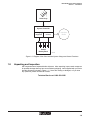
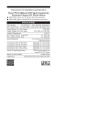
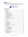
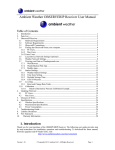
1.7
System Power Flow
Power flow is controlled by a charge controller located on the electronics panel inside the
enclosure. A diagram of the SIS power flow is shown in Figure 1-3.
1-2
RAD-SIS-24 Solar Interface Systems
Section 1 - Introduction
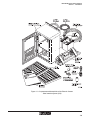
FIgure 1.1 Components and Assemblies of the Phoenix Contact
Solar Interface System (SIS)
1-3
RAD-SIS-24 Solar Interface Systems
Section 1 - Introduction
Figure 1-2. Example of Typical Solar Interface System Installation
1-4
RAD-SIS-24 Solar Interface Systems
Section 1 - Introduction
Solar Array
System Controller
Charging
Regulator
Load
Control
Interface
Radio
Sealed
Battery Bank
1984A005
Figure 1-3. Diagram of the Solar Interface System Charge and Control Functions
1.8
Unpacking and Inspection
SIS components were inspected before shipment. After unpacking, inspect each component
for possible damage that may have occurred during shipping. Items supplied with your Solar
Interface System are shown in Figure 1-1. If items are missing or damaged, or if you have
any questions, please call Phoenix Contact:
Technical Service at 1-800-322-3225.
1-5
RAD-SIS-24 Solar Interface Systems
Section 1 - Introduction
1-6
RAD-SIS-24 Solar Interface Systems
Section 2 - Technical Data
2
SECTION
Technical Data
Section 2 Contents
2.1
2.2
2.3
2.1
General .................................................................................................................... 2-1
Dimensions – Solar Modules ................................................................................... 2-4
Dimensions – SIS Enclosure ................................................................................... 2-5
General
This section provides technical information about the components that were supplied with
your Solar Interface System (SIS). You should become familiar with the specifications for
the items listed in Tables 2-1 thru 2-9. Figures 2-1 and 2-2 provide the basic dimensions for
the solar modules and the SIS enclosure.
•
•
•
•
Phoenix Contact Solar Interface System (SIS)
Solar charge controller
Solar batteries
Solar modules
Phoenix Contact reserves the right to make any necessary changes that advances the
technology and performance of the product.
Table 2-1. Phoenix Contact Solar Interface System Specifications
2-1
RAD-SIS-24 Solar Interface Systems
Section 2 - Technical Data
Table 2-2. RAD-SOL-CHG-24-10 Solar Charge Controller Specifications
Table 2-3. RAD-SOL-BAT-12-40 Solar Battery Specifications (40-watt System)
Table 2-4. RAD-SOL-BAT-12-70 Solar Battery Specifications (60-watt System)
Table 2-5. RAD-SOL-BAT-12-84 Solar Battery Specifications (80/100-watt System)
2-2
RAD-SIS-24 Solar Interface Systems
Section 2 - Technical Data
Table 2-6. RAD-SOL-PAN-12-20 Solar Module Specifications (40-watt System)
Table 2-7. RAD-SOL-PAN-12-30 Solar Module Specifications (60-watt System)
Table 2-8. RAD-SOL-PAN-12-40 Solar Module Specifications (80-watt System)
Table 2-9. RAD-SOL-PAN-12-50 Solar Module Specifications (100-watt System)
2-3
RAD-SIS-24 Solar Interface Systems
Section 2 - Technical Data
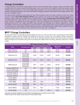
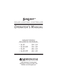
2.2
Dimensions – Solar Modules
Figure 2-1 provides dimensions for 40-, 60-, 80- and 100-watt systems.
Figure 2-1. Solar Module Dimensions
2-4
RAD-SIS-24 Solar Interface Systems
Section 2 - Technical Data
2.3
Dimensions – SIS Enclosure
Figure 2-2 provides dimensions for the SIS enclosure.
48
9
(19 .00
.25 mm
2i
n.)
m
0 m .)
7.7 in
33 .295
(13
95
.
(3. 25 m
75 m
0i
n.)
24
4
(9. .50 m
62 m
6i
19
n
3
(7. .67 m .)
62 m
5i
n.)
17
.
(0. 46 m
68 m
7i
n.)
77
.
(3. 79 m
06 m
3i
n.)
98
.
(3. 42 m 34.9
87 m (1 2
5i
m
n.) .375 m
in.
)
57
.
(2. 15 m
25 m
0i
n.)
81
2
(32 .80
.00 mm
0i
n.)
76
5
(30 .24
.12 mm
8i
n.)
1984A062
Figure 2-2. Enclosure Dimensions
2-5
RAD-SIS-24 Solar Interface Systems
Section 2 - Technical Data
2-6
RAD-SIS-24 Solar Interface Systems
Section 4 - Location Considerations
3
SECTION
SIS Location Considerations
Section 3 Contents
3.1
3.2
3.3
3.4
3.1
Solar Insolation Values Worldwide ........................................................................... 3-1
Checking Sun Path for Obstructions ........................................................................ 3-1
Solar Module Orientation ......................................................................................... 3-3
Solar Module Tilt Angle ............................................................................................ 3-4
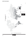
Solar Insolation Values Worldwide
It is important that solar energy provided by the SIS is sufficient to meet your load requirements.
Figure 3-1 is a map showing average solar insolation values around the world. The map
values stated are worse case and in units of kilowatt-hours per square meter. For specific
solar insolation values applicable to your area or for help with calculating daily load requirements and appropriate array size, call Phoenix Contact Technical Service at (800) 322-3225.
3.2
Checking Sun Path for Obstructions
CAUTION
The solar array must be located in an open area that will
receive unobstructed sun during the entire day throughout the year.
After determining the general location for your Solar Interface System, check sun path at that
location for obstructions:
1. On a clear day, stand at the exact spot where the Solar Interface System is to be
installed.
Note
In the winter, the sun will rise to the south of due east and set
to the south of due west. Likewise, in the summer, the sun will
rise to the north of due east and set to the north of due west.
2. Using a compass as a guide, look toward the horizon due east of your position. Then
3-1
Worse Case “Solar Insolation”
(kWh/m2/day)
Figure 3-1. Average Daily Solar Insolation Values
3-2
5–6
4–5
3–4
2–3
0–2
(kWh/m2/day)
01984A058-2
RAD-SIS-24 Solar Interface Systems
Section 3 - Location Considerations
RAD-SIS-24 Solar Interface Systems
Section 4 - Location Considerations
turn and look to the horizon due west of your position. See Figure 3-2.
3. Make sure there are no obstructions that will shade your Solar Interface System
between 9:00 am and 4:00 pm during the summer and winter sun paths. Also consider
shading from future growth or buildings.
E
NE
SE
S
SW
N
NW
W
1984A069-3
Figure 3-2. Checking Summer and Winter Sun Paths for Obstructions
3.3
Solar Module Orientation
If your site is located in the northern hemisphere, face the solar module true south. See
Figure 3-3. Similarly, if your site is located in the southern hemisphere, face the solar
module true north.
S
Solar
Module
N
Solar
Module
1984A071
Southern
Hemisphere
Northern
Hemisphere
Figure 3-3. Solar Module Orientation
3-3
RAD-SIS-24 Solar Interface Systems
Section 3 - Location Considerations
3.4
Solar Module Tilt Angle
0°
15°
30°
45°
30°
15°
0°
3-4
165° 150° 135° 120° 105° 90°
30°
45°
60°
45°
60°
75°
30°
15°
Equator
75°
60°
45°
South
Latitude
15°
North
Latitude
30°
45°
60°
75°
(Elevation Angle =
Latitude plus 15 degrees)
Solar Panel
Elevation Angle at
Various Latitudes
165° 150° 135° 120° 105° 90°
Figure 3-4. Solar Module Orientation
1984A050-3
90° 105° 120° 135° 150° 165° 180°
75°
60°
45°
15°
30°
45°
30°
60°
45°
30°
Prime
Meridian
Prime
Meridian
75°
West Longitude
15°
0°
15°
East Longitude
60°
75°
Equator
90° 105° 120° 135° 150° 165° 180°
Once the solar module has been attached to the structure, you will need to adjust the “tilt
angle” of the module to obtain optimum performance. The tilt angle is based on the latitude
at your SIS location. Therefore, you will need to know the approximate latitude of your SIS
location before setting the tilt angle. Use the map below to determine the appropriate tilt
angle.
RAD-SIS-24 Solar Interface Systems
Section 4 - Installation Procedures
4
SECTION
Installation Procedures
Section 4 Contents
4.1
4.2
4.3
4.4
4.5
4.6
4.7
4.8
4.9
4.10
4.11
4.12
General .................................................................................................................... 4-2
Safety Precautions .................................................................................................. 4-2
Tools and Equipment ............................................................................................... 4-2
Additional Material Considerations .......................................................................... 4-3
Mounting Pole .......................................................................................................... 4-3
Installing the SIS Enclosure ..................................................................................... 4-3
System Grounding ................................................................................................... 4-6
Removing Fuses from Electronics Panel ................................................................. 4-8
Installing Coax Cable Surge Protector ..................................................................... 4-9
Installing Radio and Antenna Adapter .................................................................... 4-10
Installing the Solar Modules ................................................................................... 4-11
Wiring the Enclosure ............................................................................................. 4-14
4.12.1 Enclosure Wiring ....................................................................................... 4-14
4.12.2 Wiring the Solar Module Junction Box ...................................................... 4-18
4.12.3 Grounding the Solar Module ..................................................................... 4-20
4.13. Installing the Antenna ............................................................................................ 4-21
4.14 Installing Flexible Conduit Mounting Brackets ........................................................ 4-21
4.15 Installing the Battery .............................................................................................. 4-21
4.16 Final Checkout ....................................................................................................... 4-24
WARNING
Electricity, even at low voltages, can be very dangerous.
For your protection, Phoenix Contact recommends that
all electrical installations, maintenance and repairs be
performed only by licensed and/or properly qualified
individuals and in strict accordance with applicable health,
safety, building and electrical codes.
4-1
RAD-SIS-24 Solar Interface Systems
Section 4 - Installation Procedures
4.1
General
This section provides the information necessary to install the Phoenix Contact Solar Interface System (SIS). Before installing the SIS, you should become familiar with SIS component names as defined in Section 1 and solar module orientation requirements outlined in
Section 2.
4.2
Safety Precautions
Before attempting to install and wire this SIS, please read all instructions carefully. We
recommend placing this manual in the SIS enclosure for future reference.
WARNING
Solar modules can produce hazardous voltages whenever exposed to sunlight, even when not in full sunlight.
Therefore, when working with PV modules or making
wiring connections during the daytime, cover solar modules with an opaque material.
WARNING
For your protection and protection of the equipment when
making solar module, battery or load connections, always
make sure that the SIS fuses are removed from fuse
terminal blocks located on the electronics panel of the
enclosure.
WARNING
To prevent short circuits and damage to the equipment
when installing the battery: (1) Exercise extra caution
when placing the battery into the enclosure. (2) Always
double check your positive and negative polarity before
connecting the battery cables. Always use insulated tools
when working on electrical equipment.
4.3
Tools and Equipment
No tools were supplied with your SIS. However, we suggest that you have the following
tools to ensure a successful installation.
•
•
•
•
•
•
•
4-2
Compass
Slotted-head screwdriver
Wire cutters
Crimping tool
Open-end wrench set (standard)
Pliers
Utility knife
•
•
•
•
•
•
Protractor
Phillips-head screwdriver
Stripping tool
Multimeter
Socket set (standard)
Hacksaw
RAD-SIS-24 Solar Interface Systems
Section 4 - Installation Procedures
4.4
Additional Material Considerations
The following is a list of materials you may need to complete the installation.
•
•
•
•
•
•
•
•
•
•
•
•
4.5
Foundation
Earth-ground rod, ground cable and clamps (per local codes)
Mounting pole; 63.5 mm to 76.2 mm (2-1/2 in. to 3 in.) diameter. Suitable for mounting antenna, solar module and enclosure.
Antenna
External antenna cable
Internal antenna adapter (see ordering data)
Wire for connecting external sensors, switchgear, etc.
U-bolts for pole-mounted installations, or lag screws for wall mounted installations
Wire wraps
Radios and accessories. Visit our web site: http://www.phoenixcon.com
Antenna splitter for multiple radios. Visit our website: http://www.phoenixcon.com
End clamps for additional DIN-rail mountable product (see ordering data)
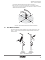
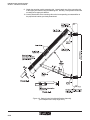
Mounting Pole
To accommodate the solar module bracket assembly provided with the SIS, the outside
diameter of the mounting pole must be in the range of 63.5 mm to 76.2 mm (2-1/2 in. to
3 in.). See Figure 4-1 for an example configuration. In addition, the pole must accommodate
an antenna and the SIS enclosure. Dimensions for the solar module and enclosure can be
found in Section 2 of this manual.
4.6
Installing the SIS Enclosure
The white powder-coated aluminum unit is designed to meet NEMA 3R and NEMA 4 standards. Figure 4-2 is a wiring diagram of the various components that make up the SIS. The
mounting system allows the enclosure to be mounted on a pole or to a wall. See Figure 4-3.
Note
The SIS enclosure has two mounting flanges, one at the top of
the enclosure and one at the bottom of the enclosure. However, U-bolts or lag bolts have not been provided with the SIS
for attaching the enclosure. Therefore, if U-bolts or lag bolts
are needed to attach the enclosure, they will have to be
obtained from your local hardware store.
4-3
RAD-SIS-24 Solar Interface Systems
Section 4 - Installation Procedures
Figure 4-1. SIS Configuration Example
4-4
RAD-SIS-24 Solar Interface Systems
Section 4 - Installation Procedures
Figure 4-2. SIS Configuration Wiring Diagram
4-5
RAD-SIS-24 Solar Interface Systems
Section 4 - Installation Procedures
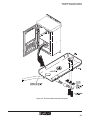
Figure 4-3. Installing SIS Enclosure Earth Ground
4.7
System Grounding
The negative for your SIS must be connected to earth ground. On the bottom (lower shelf)
of the enclosure, you will find a grounding terminal. See Figure 4-4. All SIS chassis grounds
are channeled through this terminal.
This system should be grounded per the 2002 National Electric Code. Refer to Articles 690
and 250 of the NEC. We recommend using a 13.30 mm2 (6 AWG) grounding cable (not
supplied) for making the earth-ground connection.
4-6
RAD-SIS-24 Solar Interface Systems
Section 4 - Installation Procedures
Figure 4-4. Enclosure Earth Ground Connection
4-7
RAD-SIS-24 Solar Interface Systems
Section 4 - Installation Procedures
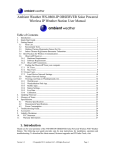
4.8
Removing Fuses from Electronics Panel
WARNING
For your protection and protection of the equipment when
making solar module, battery or load connections, always
make sure that the SIS fuses are removed from the fuse
terminal blocks located on the electronics panel of the
enclosure.
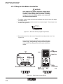
Prior to installing the antenna, solar module or other equipment, remove the three fuses from
the fuse terminal blocks on the SIS electronics panel. See Figure 4-5.
PV
BA
TT
ER
Y
2
+
SEA
LED
FLOOR
SELODE
ECTD
-
3
V
246 AC
A
063
D/
-
+ DC
OK
PLUGTRAB
DC/1
C/24
240A 0
100 84
PS : 29 38
MINI–r-No.
URE
Orde
ERAT
-28 39 T3 6KV
+31 8
+
-
+
DC
24V OK
+
1A
MINI POWER
+
22.5
28.5 –
VDC
+60°C
F
...
-25 +140°
...
-13
-25
DC
INP
UT
AC: 40V
100–2Hz
50–60 :
Range4V
85–262A
0.5–0/
0V
DC
90–351A
0.4–0.
240V
±1%
1A
S RIAL
OL
OVAL
INDUST ENT
CONTR
APPR
EQUIPM
UL
C
LISTED
tions
mains
instruc
to
1YD8
om
ation
cting ntact.c
install
conne enixco
Read
before ce.pho
nterfa
www.i
US
Electronics
Panel
ATION
OLOGY
INFORMENT
TECHN
EQUIPM
TEMP
PUT
OUT
DC
P
VP
Typ USLKG 5
24AC PE/S
- ST
:
UC
ISN:
OUT
LD+
LD
-
2
300V 20A
22AWG
300V 20A
22AWG
2
2
LO
AD
+
5
-
6
300V 20A
22AWG
+ 500V 6.3A
S 10mm
PLU
GTR
PT
2 - AB
-
1
Aluminum
Enclosure
+ 500V 6.3A
S 10mm
+ 500V 6.3A
S 10mm
-
Typ DIKD 1,5
3
Typ DIKD 1,5
-
ÖVE
+
U p: 180 V L-N
550 V L(N)-PE 25A
4
V
DC
OK
IN
DC
+
12–24
NC
NC
V
-
No. 1
Fuse Holder
(Solar Module)
No. 2
Fuse Holder
(Battery)
300V 20A
22AWG
2
300V 20A
22AWG
+ 500V 6.3A
S 10mm
2
300V 20A
22AWG
2
+ 500V 6.3A
S 10mm
+ 500V 6.3A
S 10mm
No. 3
Fuse Holder
(Load)
Cover
Holder
PL
UG
PT TRA
24A2 - PE B
U C C - /S
:
ST
IN :
3
S- 06
-
3
-
+ D
OKC
4V
2 6 AC
A
D/
-28 39 T3 6KV
+31 8
+
-
U-Shaped
Protective
Cover
OU
5 x 20 Cartridge
Fuse,125 V, 10A
(Typical)
Screw Cap
Fuse Holder
(Typical)
T
-
DC
-
MINI POWER
Cover
Holder
+
DC
24 O K
V
+
1A
+
22
.5
28 –
.5
VD
C
DC
OK
IN
+
DC
NC
12
–2
4
NC
V
-
1984A063-1
Attaching Screw
(4 places)
Figure 4-5. Solar Module, Battery and Load Fuses
4-8
RAD-SIS-24 Solar Interface Systems
Section 4 - Installation Procedures
4.9
Installing Coax Cable Surge Protector
Your SIS includes a coaxial cable surge protector for protecting the antenna and radio(s).
Install the surge protector as described in the following procedure.
1. Locate the NEMA hole seal on the lower shelf and remove. See Figure 4-6, View A.
2. Fabricate and install a ground wire 2.08 to 1.31 mm2 (14 to 16 AWG) between the
surge protector and earth-ground terminal.
3. Install surge protector and tighten the lock nut.
Figure 4-6. Installing the Coax Cable Surge Protector
4-9
RAD-SIS-24 Solar Interface Systems
Section 4 - Installation Procedures
4.10
Installing Radio and Antenna Adapter
1. Snap the radio onto the mounting rail. See Figure 4-7, View A. Secure the radio in
place by installing an end bracket on either side of the radio.
2. Wire the radio as directed by the installation instructions that came with the radio.
Once wired, plug the antenna adapter connector into the radio.
3. Remove the NEMA hole seal from one of the innermost holes in the upper shelf. See
View B. Slide a hole grommet over the antenna adapter cable and install it into the
hole. Then run the adapter cable down to the surge protector on the lower shelf. See
View C.
4. Screw the antenna adapter connector onto the surge protector.
Figure 4-7. Installing Wireless Radio and Antenna Adapter
4-10
RAD-SIS-24 Solar Interface Systems
Section 4 - Installation Procedures
4.11
Installing the Solar Modules
Notes
A 4.57 m (15 ft) length of flexible conduit and two 6.09 m (20
ft) lengths of 3.31 mm2 (12 AWG) wire (one red and one white)
were supplied with the system. If the solar module is to be
installed higher than 2.44 m (8 ft) above the enclosure, you will
need to obtain a longer length of both the conduit and the two
3.31 mm2 (12 AWG) wires.
Instructions for the solar module(s) have been provided with
the system. Familiarize yourself with the instructions before
installing your module.
1. Refer to Section 3 and calculate the solar module orientation and tilt angle for your
geographical area.
2. Determine the height at which the solar module will be installed on the pole. Refer to
Figure 4-1.
NOTE
To achieve the proper solar module orientation, the solar
module bracket assembly will have to be rotated and repositioned after installation. Therefore, pole bracket clamps and
solar module bracket bolts should not be tightened until
bracket assembly is attached and properly oriented.
3. See Figure 2-1 for dimensions of the various solar modules.
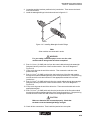
4. Figures 4-8 and 4-9 show a typical installation of a side-of-pole mounting bracket
assembly. Our example is based on the RAD-SOL-SET-24-80 system installed at an
angle of 45°.
5. Using a blade-type screwdriver, loosely install the lower pole bracket at the desired
height on the pole.
6. Loosely install the upper pole bracket approximately 800 mm (31-1/2 in.) above the
lower pole bracket.
NOTE
Figures 4-8 and 4-9 show the bracket assembly struts configured for a tilt angle of 45°. The tilt angle is based on the length
of the 2-piece telescoping strut assembly and the distance
between the two pole brackets. Moving the inside strut inward
(shortening total length) one hole position increases the tilt
angle about 5°. Similarly, moving the strut outward (increasing
total length) reduces the tilt angle about 5°. In addition, when
changing total strut length, the distance between pole brackets
will also change. The distance between pole brackets will
increase for tilt angles greater than 45° or decrease for angles
less than 45°.
7. Using Figures 4-8 and 4-9 as a guide, determine appropriate strut assembly length to
achieve the required solar module tilt angle for your particular geographic location.
8. Set the struts to the determined length. Then using at least two bolts, fasten the two
struts together and fully tighten. See Figure 4-8, View A-A. Next, loosely install the
strut assemblies to the lower pole bracket using the attaching bolts.
4-11
RAD-SIS-24 Solar Interface Systems
Section 4 - Installation Procedures
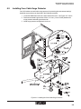
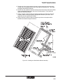
9. Obtain the two solar module mounting rails. Loosely attach one of the mounting rails
to the upper pole bracket using the attaching bolt. Similarly, loosely attach the second
mounting rail to upper pole bracket.
10. Loosely attach each of the mounting rails to their corresponding strut assemblies at
the proper hole location, previously determined.
Figure 4-8. Setting Up the Solar Module Bracket Assembly
(Our example uses a setup angle of 45°)
4-12
RAD-SIS-24 Solar Interface Systems
Section 4 - Installation Procedures
11. Position one of the solar modules so that the mounting holes at the top of the solar
module frame are aligned with the holes in the upper mounting bracket. Then install
and tighten the attaching hardware.
12. Position the solar module so that the mounting holes at the bottom of the solar module
frame are aligned with the holes in the lower mounting bracket. Then install and
tighten the attaching hardware.
13. Using a compass, rotate the lower pole bracket (including strut assembly and solar
module) so that it is facing the proper geographical direction for your area. Then
tighten the two lower pole bracket clamps.
14. Using a protractor, slide the upper pole bracket up or down on the pole until the
desired solar module tilt angle is achieved.
Figure 4-9. Installing the Solar Module Bracket Assembly
4-13
RAD-SIS-24 Solar Interface Systems
Section 4 - Installation Procedures
4.12
Wiring the Enclosure
WARNING
Solar modules can produce hazardous voltages whenever exposed to sunlight, even when not in full sunlight.
Therefore, when working with PV modules or making
wiring connections during the daytime, cover solar modules with an opaque material.
1. For safety, cover the solar module during installation and wiring to reduce the danger
of arcing or shock.
2. Obtain the two 6.09 m (20 ft) 3.31 mm2 (12 AWG) wires (red and white), flexible
conduit 4.57 m (15ft), two
12.7 mm (1/2 in.) conduit connectors, 12.7 mm (1/2 in.) coupling and 12.7 mm (1/2
in.) cord-grip connector supplied with your SIS.
4.12.1 Enclosure Wiring
1. Check that both ends of the conduit are cut straight and are not bent. If necessary,
trim one or both ends of the conduit.
2. Remove the hole knockout from one of the enclosure hole locations. See
Figure 4-10.
3. Obtain a conduit connector. Insert the body of the connector into the hole of the
enclosure and install the locknut.
4. Slide the compression nut and compression ring over the watertight jacket of the
conduit.
5. Screw the conduit end cap onto the end of the conduit.
6. Insert the end of the conduit into the connector body and tighten the compression nut.
7. Insert the two 3.31 mm2 (12 AWG) wires into the flexible conduit. Leave approximately 76.2 to 91.44 cm (30 to 36 in.) of wire available at the enclosure to reach the
enclosure's electronics panel.
8. Run the wires from the conduit through the enclosure's upper shelf. Install a hole
grommet in the upper shelf as shown in Figure 4-11. Then run the wires up to the
enclosure's electronics panel.
9. Cut wires to proper length and crimp a fork terminal to the end of each wire.
10. Attach the two wires to the enclosure's electronics panel. Refer to the wiring diagram
shown in Figure 4-2 for wire terminations.
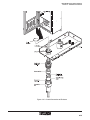
11. Assemble the conduit connector, conduit coupling and cord-grip connector as shown
in Figure 4-12. Then attach the conduit to the bracket assembly.
12. Run the wires from the cord-grip connector to the solar module junction box.
4-14
RAD-SIS-24 Solar Interface Systems
Section 4 - Installation Procedures
Figure 4-10. Conduit Connection at Enclosure
4-15
RAD-SIS-24 Solar Interface Systems
Section 4 - Installation Procedures
Figure 4-11 . Example of Shelf-to-Shelf Wiring
4-16
RAD-SIS-24 Solar Interface Systems
Section 4 - Installation Procedures
Figure 4-12. Conduit Connection at Solar Module
4-17
RAD-SIS-24 Solar Interface Systems
Section 4 - Installation Procedures
4.12.2 Wiring the Solar Module Junction Box
WARNING
Solar modules can produce hazardous voltages whenever exposed to sunlight, even when not in full sunlight.
Therefore, when working with PV modules or making
wiring connections during the daytime, cover solar modules with an opaque material.
1. For safety, cover the solar module during installation and wiring to reduce the danger
of arcing or shock.
2. Cut the wires to the solar module junction box to desired length. Then strip the wires
as shown in Figure 4-13.
Strip Length
16 mm (5/8-in.)
1984A041
12 AWG Wire
Figure 4-13. Wire Size and Strip Length Requirements
3. Remove the screws from the cover of the junction box and open the cover. See
Figure 4-14.
Note
The junction box has two hole positions for installing watertight
conduit fittings. Straight-through fittings have been supplied
with your SIS. These fittings will also act as strain reliefs for the
conduit.
Figure 4-14. Solar Module Junction Boxes
4-18
RAD-SIS-24 Solar Interface Systems
Section 4 - Installation Procedures
4. Locate the two hole knockout positions in the junction box. Then remove the knockouts from the holes.
5. Install the watertight fittings in the holes as shown in figure 4-15.
Figure 4-15. Installing Watertight Conduit Fittings
Note
Solar modules are connected in series.
WARNING
For your safety, leave the opaque cover over the solar
module until all wiring tasks have been completed.
6. Run a 3.31 mm2 (12 AWG) red wire from the control cabinet through the watertight
fitting and into the junction box of the first solar module. See circuit diagrams in
Figure 4-16.
7. Crimp a wire lug onto the end of the red wire. Then connect the red wire to the
positive terminal.
8. Run a 3.31 mm2 (12 AWG) red wire from the junction box of the first solar module
through the conduit and watertight fitting of the second junction box. Crimp a wire lug
onto the end of the wire and connect it to the appropriate terminal of the second
junction box.
9. Run a 3.31 mm2 (12 AWG) white wire from the control cabinet through the watertight
fitting and into the junction box of the first solar module. See circuit diagrams in
Figure 4-16.
10. Crimp a wire lug onto the end of the white wire. Then connect the white wire to the
appropriate terminal.
11. Run a 3.31 mm2 (12 AWG) white wire from the junction box of the first solar module
through the conduit and watertight fitting of the second junction box. Crimp a wire lug
onto the end of the white wire and connect it to the appropriate terminal.
CAUTION
Make sure that wires are connected properly. Check that
terminal screws and watertight fittings are tight.
12. Check all wire connections. Then install the junction box cover plate.
4-19
RAD-SIS-24 Solar Interface Systems
Section 4 - Installation Procedures
Figure 4-16. Circuit Diagrams for Series Wiring of Two Solar Modules
4.12.3 Grounding the Solar Module
CAUTION
If the mounting pole or structure is nonconductive, we
recommended running a separate wire to earth ground.
Grounding should be in accordance with the 2002 National Electric Code. Refer to articles 690 and 250 of the
NEC.
1. Attach a 5.26 mm2 (10 AWG) wire to the solar module as shown in Figure 4-17. Then
run the wire to a suitable earth ground.
Figure 4-17. Grounding of Solar Module
4-20
RAD-SIS-24 Solar Interface Systems
Section 4 - Installation Procedures
4.13. Installing the Antenna
Install the antenna per the antenna mounting instructions. Phoenix Contact offers a variety
of antenna solutions. See the title page of this manual for contact information.
Note
The antenna cable plugs into the surge protector in the SIS
enclosure. Therefore, when installing the antenna, make sure
that the enclosure end of the antenna cable has an industry
standard N-type male connector.
4.14
Installing Flexible Conduit Mounting Brackets
Your SIS package contains three flexible conduit mounting brackets. See Figure 4-18. To
meet specification, the distance between brackets should be 0.914 m (3 ft) or less. See
Figure 4-1 for approximate placement of the mounting brackets.
Figure 4-18. Flexible Conduit Mounting Bracket
4.15
Installing the Battery
CAUTION
Use caution when making battery connections. Your
system has two 12-volt batteries. Battery-to-battery interconnect cables are connected in series.
SIS batteries are shipped fully charged. However, if batteries have been in storage for a
long period of time, the charge in the battery may be weakened. We recommend that you
always check the resting open-circuit voltage of the battery to avoid problems. If voltage
reads below 12.4 volts, recharge the batteries before they are installed. Always use a well
regulated constant-voltage charger. Set charger no higher than 13.8 volts at a charge rate of
no more than 10 amps per battery.
4-21
RAD-SIS-24 Solar Interface Systems
Section 4 - Installation Procedures
WARNING
Solar modules can produce hazardous voltages whenever exposed to sunlight, even when not in full sunlight.
Therefore, when working with PV modules or making
wiring connections during the daytime, cover solar modules with an opaque material.
WARNING
For your protection and protection of the equipment when
making solar module, battery or load connections, always
make sure that the SIS fuses are removed from the fuse
terminal blocks located on the electronics panel of the
enclosure.
1. For safety, cover the solar module during installation and wiring of the battery to
reduce the danger of arcing or shock. Also check that the fuses have been removed
from the fuse terminal blocks. If fuses have not been removed, shut down your SIS
as described in Section 5 of this manual.
WARNING
To prevent short circuits and damage to the equipment
when installing the battery: (1) Exercise extra caution
when placing the battery into the enclosure. (2) Always
double check your positive and negative polarity before
connecting the battery cables. Always use insulated tools
when working on electrical equipment.
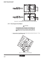
2. Figure 4-19 shows the serial cable connections for the SIS two-battery configuration.
You should become familiar with the layout of these connections.
Figure 4-19. Diagram Showing Two Batteries Connected in Series
3. Using a 7/16-in. wrench, remove the attaching bolts, flat washers and lock washers
from the positive and negative terminal post of both batteries. See Figure 4-20.
4. Carefully place the batteries on the rubber mat in the battery compartment.
5. Slide back the protective boot on the red battery cable. Then using a 11.1 mm (7/16
in.) wrench, attach the cable to the battery's negative post.
6. Slide back the protective boot on the black battery cable. Then using a 11.1 mm (7/
16 in.) wrench, attach the cable to the battery's positive post.
7. Check to make sure that the black cable is attached to the negative post and the red
cable is attached to the positive post.
4-22
RAD-SIS-24 Solar Interface Systems
Section 4 - Installation Procedures
Figure 4-20. Installing the Batteries
4-23
RAD-SIS-24 Solar Interface Systems
Section 4 - Installation Procedures
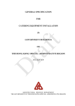
4.16
Final Checkout
Before installing fuses to energize your system, check the following parameters:
1. Check your solar module input wiring for proper open-circuit voltage and polarity.
2. Check your battery wiring for proper voltage and polarity.
3. Check polarity of wiring to loads.
CAUTION
To avoid damage to the electronic components during
start-up and shutdown modes, fuses must be removed
and reinstalled in the proper sequence. Refer to Section
5 of this manual for the proper start-up and shutdown
procedures.
4. Once your battery connections have been made and you have checked your polarity
carefully, energize the system by installing the three fuses as described in Section 5
of this manual.
4-24
RAD-SIS-24 Solar Interface Systems
Section 5 - Start-up & Shutdown Procedures
5
SECTION
Start-up & Shutdown Procedures
Section 5 Contents
5 .1
5.2
Start-Up
Once the solar module, battery and load connections have been made and you have
checked your polarity carefully, energize the system by installing the three fuses in the order
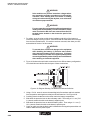
described in the following paragraphs. See Figure 5-1.
PV
BA
TT
ER
2
Y
+
SEA
LED
FLOOR
SELODE
ECTD
DC/1
/24
240AC0
100 84
PS 29 38
E
MINI–-No.:
RATUR
Order
ATION
LOGY
INFORMENT
TECHNO
-25
EQUIPM
T
INPU
0V
AC:
z
100–24
50–60H:
Range V
85–264A
0.5–0/2
22.5
28.5 –
VDC
V
DC
90–350A
0.4–0.1
RIAL
L
INDUST ENT
VALS
DC
240V
±1%
1A
APPRO CONTRO
US EQUIPM
UL
C
LISTED
1YD8
tions
instrucmains
tion to ct.com
ting
installa
connec ixconta
Read
.phoen
before
terface
www.in
P
VP
V
DC
+
12–24
NC
NC
V
FLBL-2357-04R3
RAD-ISM-900-DATA-BD
PN: 28 67 13 1
RAD-ISM-900-DATA-BD
PN: 28 67 13 1
12 - 30 VDC
350 mA
-40°C to 70°C
-40°F to 158°F
LINK CONTACT: 120 VAC 0.5 A
TEMP:
POWER:
Electronics
Panel
RX
TX
RF
RSSI
ANT
5 4 3 2 1
9 8 7 6
Trusted Wireless
SPREAD SPECTRUM TRANSCEIVER
-
APPROBATIOEN/APPROVALS
IN
WARNING: EXPLOSION HAZARD
Do not disconnect equipment unless
power has been switched off or the
area is known to be non-hazardous.
DC
OK
1845A000
+
+60°C
...
-25 +140°F
...
-13
TEMPE
PUT
+
DC
24V OK
+
1A
Made in CANADA
+ DC
OK
OUT
-
FLBL-2358-01R1
-
DC
LD
+
LD
-
-
Typ USLKG 5
3
V
246 AC
A
D/
-28 39 T3 6KV
+31 8
+
OUT
Typ DIKD 1,5
2
2
300V 20A
22AWG
300V 20A
22AWG
2
224AC
PE/S
- ST
:
UC
IS-0
N:
63
LO
AD
+
5
-
6
300V 20A
22AWG
+ 500V 6.3A
S 10mm
PLUG
PT TRAB
-
1
Aluminum
Enclosure
+ 500V 6.3A
S 10mm
+ 500V 6.3A
S 10mm
-
Typ DIKD 1,5
3
PLUGTRAB
-
ÖVE
+
U p: 180 V L-N
550 V L(N)-PE 25A
4
MINI POWER
No. 1
Fuse Holder
(Solar Module)
No. 2
Fuse Holder
(Battery)
300V 20A
22AWG
2
300V 20A
22AWG
+ 500V 6.3A
S 10mm
2
300V 20A
22AWG
2
+ 500V 6.3A
S 10mm
+ 500V 6.3A
S 10mm
No. 3
Fuse Holder
(Load)
Cover
Holder
PL
UG
PT TRA
24A2 - PE B
C - /S
:
ST
IN :
3
-
+ D
OKC
UC
S- 06
-
3
4V
2 6 AC
D/ A
-28 39 T3 6KV
+31 8
+
-
U-Shaped
Protective
Cover
OU
Cover
Holder
5 x 20 Cartridge
Fuse,125 V, 10A
(Typical)
Screw Cap
Fuse Holder
(Typical)
T
-
DC
-
+
DC
24 OK
V
+
1A
+
MINI POWER
5.1
Start-Up ................................................................................................................... 5-1
Shutdown ................................................................................................................ 5-2
22
.5
28 –
.5
VD
C
DC
OK
IN
+
DC
NC
12
–2
4
NC
V
-
1984A063-3
Attaching Screw
(4 places)
Figure 5-1. Fuses for Solar Module, Battery and Load
5-1
RAD-SIS-24 Solar Interface Systems
Section 5 - Start-up & Shutdown Procedures
1. Install fuse No. 2 (Battery). See Figure 5-1. This will connect the battery to the charge/
load controller. Check battery voltage at the controller terminals 1 and 2 under BATTERY.
2. Install fuse No. 3 (Load). See Figure 5-1. This applies DC battery voltage to the
charge/load controller terminals 5 and 6 under LOAD. Next, check that load operations
are functioning properly.
3. Install fuse No. 1 (Solar Module). See Figure 5-1. Once fuse No. 1 is installed, you
should see the green charging LED on the charge/load controller light up. See
Figure 5-2. Furthermore, depending on sunlight intensity, you should see the battery
voltage start to rise. Your solar array output will depend directly on sunlight intensity.
Only during the peak sun hours on a very clear day will you see the full rated current
from the array.
5.2
Shutdown
1. When shutting down the system, it is always best to remove fuse No. 1 (Solar Module)
first. Refer to Figure 5-1. Then remove fuse No. 2 (Battery) and fuse No. 3 (Load).
This will remove the high voltage charging source from the circuit. Normally, you do
not want to have the solar module array active (fuse installed) without the battery circuit
activated.
Charging LED
(Green)
LOAD
DISCONNECT
CHARGING
SOLAR CONTROLLER
Nominal Rating
12 Volts dc
Solar In 10A
Load 10A
See Operator’s
Manual
SOLAR
4
+
-
SS-10L
TEMP Sense
BATTERY
3
2
+
12 V
1
-
LOAD
6
+
5
-
SEALED
OR
FLOODED
SELECT
Remove
Jumper
Wire for
Flooded
Battery
MORNINGSTAR
1984A021-2
Figure 5-2. Charge/Load Controller Charging LED
5-2
RAD-SIS-24 Solar Interface Systems
Section 6 - Operation
6
SECTION
Charge Controller
Section 6 Contents
6.1
6.2
6.3
6.4
6.5
6.6
6.7
6.1
General .................................................................................................................... 6-1
General Safety Precautions ..................................................................................... 6-2
6.2.1 Charge Controller ....................................................................................... 6-2
6.2.2 Batteries ..................................................................................................... 6-2
Connecting the Charge Controller ........................................................................... 6-2
Indication Elements ................................................................................................. 6-4
6.4.1 Green LED .................................................................................................. 6-4
6.4.2 Red LED ..................................................................................................... 6-4
Operation ................................................................................................................. 6-4
Errors ...................................................................................................................... 6-4
6.6.1 Battery Not Charging .................................................................................. 6-5
6.6.2 Battery Voltage is Too High ......................................................................... 6-6
6.6.3 Operating Error of the Load ........................................................................ 6-6
6.6.4 System Goes Into Low Voltage Disconnect (LVD) State Too Often ............. 6-7
Solar Charging System ............................................................................................ 6-7
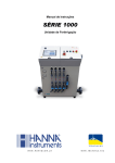
6.7.1 Test the Solar Module – Open Circuit Voltage ............................................. 6-7
6.7.2 Test the Solar Module – Short Circuit Current ............................................. 6-8
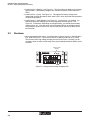
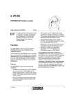
General
The SunSaver charge controller is a fully automatic controller for photovoltaic systems. See
Figure 6-1. It provides electronic protective functions for both the controller and solar
modules. The batteries are charged using an algorithm for pulse width modulation with
constant voltage, which has been optimized for photovoltaic systems.
Figure 6-1. SunSaver Charge Controller
CAUTION
The solar system is delivered with two gel-type batteries
(sealed batteries). When using this type of battery, the
jumper (6) must NOT be removed.
6-1
RAD-SIS-24 Solar Interface Systems
Section 6 - Operation
6.2
General Safety Precautions
Keep this manual in a safe place (e.g. in the enclosure) for future reference. It contains
important information that must be observed when installing and maintaining the SunSaver
charge controller and the batteries.
6.2.1
Charge Controller
WARNING
• The nominal voltage and the nominal current of the
charge controller must not be exceeded. Only use a
charge controller with a 24-volt battery (or two 12-volt
batteries connected in series).
• Do NOT short circuit the solar modules and the loads
as long as they are connected to the charge controller.
Otherwise, damage to the charge controller may occur.
• Protect the charger controller against direct sunlight.
Also ensure that there is adequate space for air circulation around the charge controller.
Only use copper wires with a minimum insulation
rating for 75° (167°F) and a cross section of at least
3.31 mm2 (12 AWG).
• Ground the negative wire of the system according to
local regulations.
6.2.2
Batteries
WARNING
• Exercise extra caution when handling the batteries.
Lead-acid batteries may produce explosive gasses and
high short-circuit currents.
• Observe all the instructions supplied with the battery.
6.3
Connecting the Charge Controller
The SunSaver charge controller is mounted on a vertical surface in the control cabinet.
Adequate space for air circulation is provided above and below the controller.
CAUTION
Make sure that the current strength of the solar module
and the loads does not exceed the rated values of the
SunSaver model installed.
6-2
RAD-SIS-24 Solar Interface Systems
Section 6 - Operation
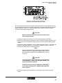
Figure 6-2. SunSaver Charge Controller
Terminal Number Identification and Jumper
The six connection terminals of the charge controller are labeled on the controller and must
be connected as described in the following steps and in accordance with the wiring diagram
shown in Section 4, Figure 4-2. Figure 6-2 identifies the SunSaver charge controller's
terminal numbers and the jumper location.
CAUTION
Make sure that live wires do NOT touch the metal housing
of the charge controller.
1. Connect the batteries to terminals (1) and (2) under the heading "BATTERY."
2. Connect the solar modules to terminals "3" and "4" under the heading "SOLAR." Note
that the green LED "CHARGING" will light up as soon as the solar modules generate
current.
3. Connect the loads to terminals "5" and "6" under the heading "LOADS." Note that if the
red LED "LOAD DISCONNECT" is on, the battery voltage is too low. In this case,
recharge the batteries prior to starting the system.
Note
When using sealed batteries, make sure the jumper is installed
between terminal "5" (under the heading "LOAD") and the
terminal labeled "SEALED OR FLOODED SELECT." Refer to
Figure 6-2.
CAUTION
The solar system is delivered with two gel-type batteries
(sealed batteries). When using this type of battery, the
jumper must NOT be removed.
Do NOT connect any wires from ("SOLAR"), ("BATTERY")
or ("LOAD") terminals to the "SEALED OR FLODED SELECT" terminal.
4. Ground the negative pole of the battery to ensure efficient grounding of the solar
system.
6-3
RAD-SIS-24 Solar Interface Systems
Section 6 - Operation
6.4
Indication Elements
6.4.1
Green LED
The green LED "CHARGING" will come ON as soon as sunlight is available for charging the
battery. The LED will be OFF in the dark.
The SunSaver charge controller charges the batteries using a pulse-width modulation
method. Therefore, the battery is always provided with a certain amount of power. Although
the charging current is very low when the batteries reach their fully charged state, the green
LED is ON (during daylight). This indicates proper operation of the charge controller.
6.4.2
Red LED
SunSaver models with an automatic load disconnect (LVD – Low Voltage Disconnect)
function are provided with a red "LOAD DISCONNECT" LED. As soon as the charging state
of the batteries falls below the low voltage disconnect set point, the load is disconnected and
the red LED will come ON. This indicates that the controller has disconnected the load to
protect the batteries from deep discharging and possible damage.
If after some charging time, the batteries reach 40 to 50% of their normal power, the load is
automatically reconnected and the red LED will go OFF.
6.5
Operation
With all fuses installed, the system should be operating normally. During normal operation,
depending on weather conditions, the battery voltage will vary from approximately 23.0 to
28.6 volts. If the battery voltage falls below 23.0 volts, the controller will go into LVD (Low
Voltage Disconnect) and open the load connections. It will then let the batteries recharge up
to approximately 25.2 volts before reconnecting the loads to the battery.
During normal operation, the battery voltage should not change rapidly. During the day and
after a night of discharge, the voltage will climb slowly up to the charge regulation set point.
Depending on the present and previous sunlight conditions, the batteries may or may not
reach the full charge regulation set point during the day.
6.6
Errors
WARNING
Electricity, even at low voltages, can be very dangerous.
For your protection, Phoenix Contact recommends that
all electrical installations, maintenance and repairs be
performed only by licensed and/or properly qualified
individuals and in strict accordance with applicable health,
safety, building and electrical codes.
CAUTION
A battery may cause serious damage when short circuited.
Observe all precautions when working on live circuits.
The SunSaver charge controller does not contain fuses,
circuit breakers or parts that can be maintained by the
user.
6-4
RAD-SIS-24 Solar Interface Systems
Section 6 - Operation
6.6.1
Battery Not Charging
The following procedure lists the basic steps for removing an error.
1. Check if green "CHARGING" LED is ON. During the day, the green LED must be ON.
2. Check if the correct battery type (sealed or flooded) has been selected. Refer to
Paragraph 6.3 for "Connecting the Charge Controller."
3. Check that all wires have been connected properly to the terminals.
4 Check all terminals for correct polarity (+ or -).
5. Measure the open-circuit voltage of the solar module as described under Paragraph 6.7
("Solar Charging System").
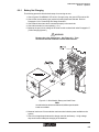
WARNING
Remove the solar module fuse. See Figure 6-3. Then
disconnect the solar modules from the load controller.
Figure 6-3. Solar Module, Battery and Load Fuses
Note
As solar isolation varies around the world, different permissable
loads are available.
6. Measure load to see if it exceeds the maximum solar isolation power available to the
system.
7. Check for voltage drops between the charge controller and battery. A high voltage
drop would cause inadequate charging of the batteries.
6-5
RAD-SIS-24 Solar Interface Systems
Section 6 - Operation
8. Disconnect the battery cables from terminals no. 2 and no. 3 of the charge controller.
Then measure the voltage between the cables. If battery voltage is reduced, the
battery(ies) may be damaged or defective. Replace battery(ies) if necessary.
9. Measure the voltage of the solar modules and the voltage of the battery at the charge
controller.
a. If voltages at the terminals are the same (within one or two-tenths of one volt), the
solar modules are charging the batteries.
b. If the photovoltaic voltage is almost as low as the open-circuit voltage of the cells,
and the battery voltage is low, the charge controller is not charging the batteries.
Check battery for damage or defects.
6.6.2
Battery Voltage is Too High
1. Check if the maximum end-of-charge voltage (14.1 V to 14.7 V) is exceeded.
2. Check if the correct battery type (sealed or flooded) has been selected. Refer to
Paragraph 6.3 for "Connecting the Charge Controller."
3. Check that all wires have been connected properly to the terminals.
4. Disconnect the solar modules from pins 3 and 4 of the charge controller.
a. With solar modules disconnected, unhook the wire momentarily from the positive
pole of the battery. Then reconnect it. At this point the green "CHARGING" LED
should be OFF.
b. With solar modules disconnected, measure the voltage at the SOLAR terminals 3(-)
and 4(+) of the charge controller. If the green "CHARGING" LED is ON, or if battery
voltage is present at the SOLAR terminals, the charge controller might be damaged.
Replace charge controller if necessary.
c. Reconnect the solar modules to pins 3 and 4 of the charge controller.
6.6.3
Operating Error of the Load
1. Check if voltage is applied at the load.
2. Check if a system fuse has failed. See Figure 6-3. The charge controller does not
contain any fuses or circuit breakers.
3. Check that the load and other terminals on the charge controller and on the battery
have been connected properly.
4. Check that voltage drops in the system wiring are not too high.
5. Check that LEDs on the charge controller indicate the proper state. Refer to
Figure 6-1.
a. If the red "LOAD DISCONNECT" LED is ON, the load has been disconnected
because of low battery voltage. This is a normal state if the load requires more
power than that provided by the solar modules. Poor weather or sunlight conditions
could exist.
6. Measure the voltage between "BATTERY" terminals 1(-) and 2(+) on the charge
controller. If voltage is below the low-voltage disconnect value, power will not be
available to the load.
7. Measure the voltage between "LOAD" terminals 5(-) and 6(+) of the charge controller.
If no voltage is present, the charge controller might be damaged. Replace if necessary.
6-6
RAD-SIS-24 Solar Interface Systems
Section 6 - Operation
6.6.4
System Goes Into Low Voltage Disconnect (LVD) State
Too Often
If the system is going into LVD too often, your daily load power draw may have exceeded the
solar system output.
a. Recalculate your present load requirement . If the recalculation shows that the solar
system is properly sized, batteries with a higher capacity or a larger solar module
can be used.
b. Please contact Phoenix Contact Technical Support if the calculation shows that the
dimensions of your solar system are not sufficient. Here you will learn whether it is
possible to expand the components in order to increase the output power of your
solar system.
c. Your sealed gel-cell batteries should last between 2 to 4 years depending on the
regular depth of discharge and temperature experienced. A symptom of diminished
battery capacity is the load working during the day, but not at night. In this case, the
battery voltage drops down to the LVD or load disconnect set point at night and then
rises up out of LVD in the day with the solar charging current.
You will see evidence of this during the day if you turn the solar module on and off.
If the voltage falls rapidly with the solar module off, and then rises rapidly when
turned on, it is time to replace the batteries.
Note
Spare batteries are available from Phoenix Contact. See
Section 7, Ordering Data.
6.7
Solar Charging System
During normal operation, the available current from the solar module(s) will be fed through
the controller directly to the batteries until the Charge Termination Voltage is reached. If you
suspect a problem with charging from the solar module, check the following.
6.7.1
Test the Solar Module – Open Circuit Voltage
WARNING
Solar modules can produce hazardous voltages whenever exposed to sunlight, even when not in full sunlight.
Unless sunlight is required for testing purposes, always
cover the face of the solar module(s) completely with an
opaque material to stop the production of electricity.
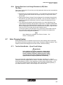
First, remove fuse No.1 (Solar Module) from its fuse holder. See Figure 6-1. Using a
multimeter, check the voltage at the PV+ and PV- terminals of the charge controller. Voltage
should read between 18 and 21 volts, depending on solar module cell temperature. If not,
you may have a problem with the solar modules. Next, check each module separately. If
you suspect a problem, contact Technical Support at 1-800-322-3225.
6-7
RAD-SIS-24 Solar Interface Systems
Section 6 - Operation
6.7.2
Test the Solar Module – Short Circuit Current
WARNING
Solar modules can produce hazardous voltages whenever exposed to sunlight, even when not in full sunlight.
Therefore, when working with PV modules or making
wiring connections during the daytime, cover solar modules with an opaque material.
First, remove fuse No.1 (Solar Module) from the fuse holder. See Figure 6-1. You will need
to use a digital multimeter configured for DC amps. Carefully isolate each solar module in
your array and connect the meter probes to the PV+ and PV- terminals of the solar module.
You should be reading the maximum Short Circuit Current for the given sunlight intensity on
the solar module. Short circuit current varies with sunlight intensity. You will probably see
less than the full rated amps most of the time. Estimate the given sunlight intensity and
correlate it with the current reading. Refer to Section 2 for the voltage and current specifications of your modules. If you suspect a problem, contact Technical Support at 1-800-3223225.
6-8
RAD-SIS-24 Solar Interface Systems
Section 7 - Ordering Data
7
SECTION
Ordering Data
Section 7 Contents
7.1
7.1
General .................................................................................................................... 7-1
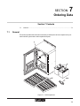
General
This section provides the information necessary to identify the various components of your
solar interface system and to order replacement parts.
Figure 7-1. SIS Components
7-1
RAD-SIS-24 Solar Interface Systems
Section 7 - Ordering Data
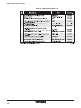
Table 7-1. Parts List for Figure 7-1*
7-2
RAD-SIS-24 Solar Interface Systems
Section 7 - Ordering Data
Figure 7-2. SIS Enclosure Electronics Panel
7-3
RAD-SIS-24 Solar Interface Systems
Section 7 - Ordering Data
Table 7-2. Parts List for Figure 7-2*
7-4
RAD-SIS-24 Solar Interface Systems
Section 8 - Warranty/Repair Information
8
SECTION
Warranty/Repair Information
Section 8 Contents
8.1
8.1
Solar Interface System (SIS) Limited Warranty ........................................................ 8-1
Solar Interface System (SIS) Limited Warranty
Phoenix Contact Inc. warrants its Solar Interface System products against defects in materials and workmanship under normal use and service for a period of 12 months from the date
of purchase.
During the warranty period, products determined by Phoenix Contact to be defective, shall at
the option of Phoenix Contact, either be repaired at a location authorized by Phoenix Contact
(and returned free of charges for parts, labor, or shipping), or replaced with an equivalent
product. Defective parts replaced by Phoenix Contact shall become the property of Phoenix
Contact. This Limited Warranty does not cover on-site repair of products. Defective products must be returned to Phoenix Contact to be repaired or replaced. Phoenix Contact is not
responsible for the operation, damage, availability, or loss of use, of the customer-supplied
equipment being used with a Solar Interface System (SIS).
This warranty is void under the following circumstances:
1. Abnormal use of the product or use in violation of the instructions provided in this
manual.
2. Improper and/or unauthorized installation or repair of system components.
8-1
RAD-SIS-24 Solar Interface Systems
Section 8 - Warranty/Repair Information
8-2
Solar Interface Systems
User Manual