1
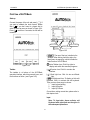
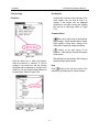
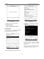
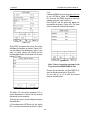
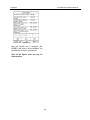
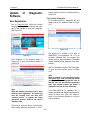
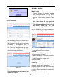
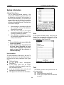
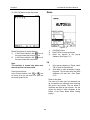
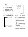
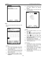
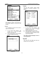
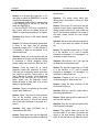
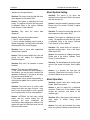
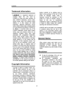
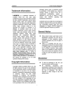
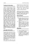
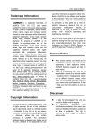
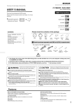
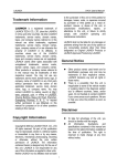
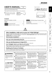
LAUNCH
AUTOBook Operation Manual
Outline of AUTOBook
Figure 2-01 outline of AUTOBook
Ports and Indicators
See Figure 2-02 for AUTOBook connection ports and indicators.
Figure 2-02 ports and indicators
Note: The serial port is just designed for manufacturer.
i
LAUNCH
AUTOBook Operation Manual
Hardware Configuration
For vehicle diagnosis, some accessories (e.g. connectors and cables) should be used to connect
AUTOBook to vehicle diagnostic socket.
AUTOBook configuration is as shown in Figure 2-03.
Figure 2-03
No.
Name
1
Main
Unit(with
Smartbox)
2
3
4
5
6
7
8
Main cable
Diagnostic
connector
Cigarette lighter
cable
Battery
cable
w/two clips
CF card reader
USB cable
CF card
Description
Perform vehicle diagnosis, and the screen of main
unit can display the operation buttons, the test
result and the help information.
Connect the AUTOBook and diagnostic connector
Dozens of connectors are provided/available for
various vehicles. Here shows a typical one.
Get power from the vehicle cigarette lighter
Get power from the vehicle battery
Read or write data from/to the CF card
Connect CF card reader and computer
Store diagnostic software and data
2
LAUNCH
AUTOBook Operation Manual
First Use of AUTOBook
Start-up
Connect the power of the unit and press [
]. If
you want to calibrate the touch screen, please
click [ ]. If you don’t want to, please wait to
enter the start-up menu as shown in Figure 2-04.
Press [ ] more than 2 seconds, the unit will be
turned off.
Active task
Overturn
Current time
Soft keyboard
Figure 2-05
[
]: The use of the icon is similar in the
windows. After clicking it with the stylus, the
[start] menu is popped up, which includes the
main functions of AUTOBook.
[ ]Active Taskbar Icon: Click it by stylus to
display and switch the executed programs.
Figure 2-04
Taskbar
] Overturn Icon: Click it to overturn the
interface.
[
] Back Light Icon: Click it to turn on/off back
light.
] Soft Keyboard Icon: To display or hide soft
[
keyboard. Click it to activate the soft keyboard.
Then you have three ways to choose:
1. Input by hand writing.
2. Input by English.
3. Input by Chinese.
[
The taskbar is at bottom of the AUTOBook
operation interface, which has several icons, and
the functions as follow :( see Figure 2-05)
Current time: setting current time, please refer to
this chapter clock.
Input
Note: To input data, please activate soft
Keyboard with stylus and use the stylus in
the subsequent operations.
3
LAUNCH
AUTOBook Operation Manual
Using the Soft Keyboard
cursor leftward, rightward, upward or
downward. The other four functions are (from
left to right): to delete the first character before
the current cursor, clear the hand-writing
section, space and return.
Activate and Hide
Input by Soft Keyboard
You have two ways to choose. One is to input
by Soft Keyboard just like normal keyboard.
The other is to input by writing board.
Click [En] button, it will switch from normal
keyboard to writing board [HW]. And click [HW]
button, it will switch back.
z The Function Key
There are four function keys on the upper-right
of the Soft Keyboard. SBC/DBC case,
punctuations, Keyboard/Writing board, and the
Soft Keyboard position can be determined by
clicking one of the four keys for each of the
functions from left to right. (Refer to Figure
2-06)
z
z
z
Input by Keyboard
1) Open an interface, such as User
information.
2) Click Soft Keyboard Icon in the tool bar
to activate Soft Keyboard.
3) Click the characters on Soft Keyboard to
enter data. (Refer to Figure 2-08)
z
Input by Writing Board
1) Open an interface, such as Memo.
2) Click [New] button.
3) Click the function key to switch to Writing
Board. (Refer to the section “Use for Soft
Keyboard”).
4) Write on the white board to the right of the
Soft Keyboard. Enter the information by
function key operation.
Figure 2-06
The four function keys at the upper-middle
position are for moving the cursor leftward,
rightward, upward or downward.
In keyboard mode, the key at the bottom left of
the keyboard is [Shift] key. Click it to change
the lowercase letter into the uppercase letter,
and the numeral key into special symbol
(same as the special characters corresponding
to the numeral keys in normal keyboard). The
white key at the bottom right of the Soft
Keyboard is space key.
Figure 2-08
Figure 2-07
In writing board mode (refer to Figure 2-07),
there are eight function keys at the lower left
of the soft keyboard. The four ones on the
bottom implement the function: to move the
4
LAUNCH
AUTOBook Operation Manual
Scrolling Bar
Control of App
Check Box
Scrolling Bar is usually at the right side of the
touch screen. You can click or drag it to
operate. If the content can’t be displayed
completely in one page, moving the Scrolling
Bar can turn to next page. (Refer to Figure
2-10)
Common Button
[ ] Button at top right corner of the interface:
After clicking it, current interface will be closed.
When editing is being done, clicking of the
button will be treated as quitting the editing.
[
] Button at top right corner of the
interface:After clicking it, the help information
will be shown.
Figure 2-09
[Cancel] Button in the interface: After clicking it,
current interface will be closed.
Click the check box to select the function.
When the function is selected, 'X' will be
marked in the check box and the function
description will be displayed on the right of the
check box. You can select several functions at
the same time. (Refer to Figure 2-09)
Help
Click [ ] button at the top right corner of the
interface to get helpful tips for current interface.
Figure 2-10
5
LAUNCH
AUTOBook Operation Manual
AUTOBook main cable.
Vehicle Diagnosis
♦ From battery: clamp the two clips of
battery cable on the positive and
negative poles of battery and insert
another end of the cable into the power
connector of AUTOBook main cable.
Conditions for Test
z Turn on the key.
z The voltage of vehicle battery should be
11-14V. The rated voltage of the
AUTOBook is 12V (AUTOBook would not
be damaged under 24V condition).
z The throttle should be in the closed
position.
z AUTOBook works in the temperature
range of 0-50 ℃ . (30 minutes of
warming-up may be necessary when the
ambient temperature is 5℃) .
♦ From power adapter: connect the
power adapter to the 100-240V AC
outlet with power cord. Insert the 12V
DC plug of power adapter into the
power connector of AUTOBook main
cable.
Operation
Select Diagnostic Connector
More and more vehicle, models and systems
can be tested by AUTOBook. Please log on
http://www.X431.com and update the latest
software in time.
Various diagnostic connectors are supplied
with AUTOBook. Select a specific connector
according to the tested vehicle. Refer to
Appendix.
Entering Function Menu
After connection, press [
AUTOBook.
Diagnostic Socket Location
Different vehicles have different socket
locations. Please refer to Appendix.
Note: the power indicator will always be lit
after being powered and during working.
Connection
z
z
z
] key to start
After starting the main unit, press [ ] (or click
[Start] button on Main Menu, and select [GAG]
→[GD Scan] on the pop-up menu), the screen
will display the home page of vehicle diagnosis
as shown in Figure 3-01.
Insert one end of AUTOBook diagnostic
cable to diagnostic interface of AUTOBook.
Connect the other end of AUTOBook
diagnostic cable to the desired diagnostic
connector.
Connect the other end of the diagnostic
connector to the vehicle diagnostic socket.
Note:
If the power supply on vehicle diagnostic
socket is insufficient or the power pin is
damaged, you can get power in the
following ways:
♦ From cigarette lighter: insert one end
of the cigarette lighter cable into the
lighter socket in vehicle and connect
the other end to the power connector of
6
LAUNCH
AUTOBook Operation Manual
page, it is inactive if the current page is
the first page.
♦ [PAGE DOWN]: to display the next page,
it is inactive if the current page is the
last page.
♦ [HELP]: to display the help information.
Click the icon of DEMO on the [vehicle make]
menu. The screen will be displayed as shown
in Figure 3-03. Select the version that you
need or the latest version. The latest version
of the software is compatible with all the
issued versions.
Note: here we take DEMO as an example to
describe diagnosis procedures for
demonstration.
Figure 3-01
Button descriptions:
♦ [QUIT]: to exit the diagnostic program.
♦ [BOX INFO.]: to display hardware and
software version of SMARTBOX.
♦ [HELP]: to display help information.
♦ [START]: to start the diagnosis.
Click [START] button, the screen will display
[Vehicle Make] menu as shown in Figure 3-02.
Figure 3-03
Button descriptions:
♦ [BACK]: to return to the previous
interface.
♦ [HELP]: to display the help information.
Click [Demo program V11.05]. The display will
be as shown in Figure 3-04
Figure 3-02
Button descriptions:
♦ [BACK]: to return to the previous
interface.
♦ [PAGE UP]: to display the previous
7
LAUNCH
AUTOBook Operation Manual
Figure 3-04
Figure 3-06
Click [OK] button, AUTOBook begins reset
and check the SMARTBOX, and download the
diagnostic program from the CF card. After
download, the screen will be displayed as
shown in Figure 3-05
If there are several pages for the menu,
please click [PAGE DOWN] to see the next
page.
Note:
The test operation for different systems is
similar. Here we take [Engine] as an
example to describe.
Button descriptions:
♦ [HOME]: to return to the homepage of
vehicle diagnosis.
♦ [BACK]: to return to the previous
interface.
♦ [HELP]: to display the help information.
Click [Engine]. If the communication is
successful, the screen will display the function
menu as shown in Figure 3-07.
1. Read fault code
2. Erase fault code
3. Read data stream
4. Actuation test
Figure 3-05
Button descriptions:
[OK]: to go on the test.
Control module
Click [OK] button, the screen will display the
menu of test systems as shown in Figure 3-06
8
LAUNCH
AUTOBook Operation Manual
the display will be as shown in Figure 3-09.
Figure 3-07
Figure 3-09
Read Fault Code
Click [OK] button to return to the function
menu.
Click [Read Fault Code in the function menu.
AUTOBook starts to test the fault code. The
screen will display the test result when the test
is finished.
Erase Fault Code
Click [Erase Fault Code] on the function menu.
AUTOBook starts to erase the fault code. (See
Figure 3-10).
Figure 3-08
Button descriptions:
♦ [HOME]: to return to the homepage of
vehicle diagnosis.
♦ [BACK]: to return to the previous
interface.
Figure 3-10
After erasing codes, the screen will display as
shown in Figure 3-11.
If there is no fault code in the tested system,
9
LAUNCH
AUTOBook Operation Manual
Figure 3-11
Figure 3-13
Click [OK] to return to Function Menu.
For example, here we select all the items on
the first page.
Button descriptions:
♦ [OK]: to return the function menu.
Read Data Stream
On the function menu, click [Read Data Stream]
to read the datastream. See Figure 3-12.
Figure 3-14
As Figure 3-14 shows, the selected options
will be displayed in white on the black
background.
And then we click [OK], the screen will display
the datastream as shown in Figure 3-15:
Figure 3-12
The screen will display as shown in Figure 3-13.
10
LAUNCH
AUTOBook Operation Manual
Figure 3-15
Figure 3-17
Click [GRAPHIC 1]. The screen will display the
chosen waveform as shown Figure 3-16.
Note:
♦ The screen will display the live value of
data stream again if the [DIGITAL]
button is clicked in the interface.
♦ The three display modes -- [DIGITAL],
[GRAPHIC-1] and [GRAPHIC-2] can be
switched in turn.
Record Data Stream
Record data stream function is mainly used for:
A. Recording and saving the data under
normal driving status as the standard
value for reference;
B. Snapping and recording pending
trouble codes for analysis.
If you want to record the selected data stream,
please click [SAVE] in Figure 3-15. The screen
will display the menu as shown in Figure 3-18.
Figure 3-16
Click [GRAPHIC-2] to display the waveforms
of 2 data stream items. See Figure 3-17. It is
convenient for the user to make live
comparison between two correlative data
stream items.
11
LAUNCH
AUTOBook Operation Manual
Figure 3-18
Figure 3-20
Note: the SAVE in Figure 3-15 equals a
menu. Only after entering this menu, can
you save, display and clear data
After inputting the file name, you may use stylus
] again, and the soft keyboard will be
to click [
hidden. The screen will display as shown Figure
3-21, and click[OK] to return to the Datastream
Menu. Now it starts to save datastream.
Click [SAVE] to enter the interface as shown in
Figure 3-19. Please enter the file name which
can be composed of letters and numbers.
Figure 3-21
Figure 3-19
], and the soft keyboard will be
Click[
displayed as shown in Figure 3-20. And then you
can use stylus to input letters and numbers.
12
LAUNCH
AUTOBook Operation Manual
3-18.
b.Download DEMO program from www.x431.com
to your AUTOBook, power AUTOBook through
DC, and start the DEMO program to enter the
interface as shown in the Figure 3-18.
Click DISPLAY and the screen will display the
recorded file as shown in Figure 3-24. The name
of file is composed of letters and numbers.
Figure 3-22
Click [STOP] to terminate the record. The screen
will display the interface as shown in Figure 3-23.
You may judge if the datastream is good. If you
think it is good, please click [Good] and the
recorded data stream will be saved into the save
folder in CF card.
Figure 3-24
Note: if there is more than one page in the
file, you can click PAGE DOWN to view.
Choose one recorded file, and click DISPLAY to
enter the interface as shown in Figure 3-25.
You can click [<-] or [->] to view the previous
frame or the latter frame.
Figure 3-23
The data in CF card can be uploaded to PC or
service department of Launch and the recorded
data stream can be analyzed.
There are two ways to review, display and replay
the saved data:
a. Re-communicate AUTOBook with the vehicle
ECU, and enter the interface as shown in Figure
13
LAUNCH
AUTOBook Operation Manual
Figure 3-25
After this function test is complete, click
[HOME]; it will return to the Home Menu. You
can select other items to continue test.
Note: all the figures above are only for
demonstration.
14
LAUNCH
AUTOBook Operation Manual
Update of
Software
accept” button to enter the interface shown in
Figure 4-02.
Diagnostic
Fill in Product Information
User Registration
Fill in product serial No., registration No. and
dealer code in the interface shown in Figure
4-03.
Log on www.X431.com. Select the favorite
language on the pull-down menu at the lower
right of the interface to enter the homepage.
See Figure 4-01.
Figure 4-03
The serial No. is marked on the back of
SMARTBOX. The registration No. is in an
envelope delivered with the product (the
number must be kept confidential). The dealer
code is attached on the last page of the user’s
manual.
Figure4-01
Click “Register” in the interface shown in
Figure 4-01 to open the window as shown in
Figure 4-02.
After the information is filled, click “Next step”
to enter the next interface shown in Figure
4-05.
Note:
When a product is sold, the dealer will log
onto www. X431. com and enter the dealer
code in the “Dealer administration” area so
that the user can do effective registration
later. User should contact the dealer if
registration can not be done effectively.
Figure4-02
Note:
When the member purchases one or more
products after registration, he should log
onto the member area, and then click
“product control” to register the newly
purchased product. Refer to the section
“Member login”.
If the filled serial No. or registration No. is
invalid, the screen will display the message as
shown in Figure 4-04. Click “OK” button to
return to the previous interface to re-fill the
correct numbers.
The terms of service is shown in the screen.
After reading and fully understand it, click “I
15
LAUNCH
AUTOBook Operation Manual
Software Update
Member Login
The user becomes the registered member
after registration. Member can log in the
website by filling username, password and
user type in the interface shown in Figure
4-01.
Figure 4-04
Fill User Information
Note: when choose the user type, the
common users may choose the customer.
If the dealer and the branch want to log to
the website, please use the user
information given by LAUNCH head office.
After log successfully, the screen will display the
interface as shown in Figure 4-07.
Figure 4-05
After information is filled in the interface shown
in Figure 4-05(The red textbox must be filled.
After registration, we will send the confidential
information to your registered e-mail, so
please make sure that your e-mail is valid.),
click “Next step”, then the screen will display
the interface shown as Figure 4-06. Click “OK’
then the registration is completed.
Figure 4-07
[Download Center]: Refer to “software
download”.
[Purchase Center]& [Update center]: Refer to
“software purchase and update”.
[Member Information]: to display and renew the
current member information.
[Product Registration]: Register newly
purchased product.
[Order Information]: to check or cancel the
unpaid order.
[Renew Password]: After entering the right old
password, then can renew the password.
[Awarded collection for claim] if users meet some
trouble during the operation, feedback to
LAUNCH. Effective complaint will be awarded by
LAUNCH
[Logout]: Users exit the registration.
Figure 4-06
Note:
Only the registered user can download and
update the software.
16
LAUNCH
AUTOBook Operation Manual
Software Download
After log successfully, the screen will enter the
[download center] interface. (See Figure4-07)
Registered user can download the software
that installed in the download center.
Before download, users had better set up a
new folder named [AUTOBook update] on the
computer desktop and put the download file to
the [AUTOBook update] according the next
steps.
Note:
1.
2.
Figure 4-08
Software update of free charge will
be provided by LAUNCH for one
year. The free period is from the
registration date on the website,
not the purchase date. That is,
during one year after the
registration, users can free
download
the
corresponding
software.
If there is not the latest version in
the download center, users can buy
the version in the purchase center
or in the update center. In the
purchase center, users can buy the
software that don’t install in the
download center. In the update
center, users can buy the software
that is beyond the free download
period. After purchase successfully,
the purchased software will be
automatically added in the
download center list.
Click [save] to put into the [AUTOBook update].
Display Program Download
When download the diagnostic program, users
can also download the display program. On the
drop-down menu, users select the language then
click [down]. On the pop-up menu, click [save] to
put the program into the[AUTOBook update].
System Data Download
On the drop-down menu, users select the
language then click [down]. On the pop-up menu,
click [save] to put the program into
the[AUTOBook update].
Diagnostic Program Download
On the drop-down menu, select the language
and the version (default version is the latest
version). Click [down] icon, then click [save] on
the pop-up menu to save the file.
Click [view] to learn the detailed information of
the version.
Users can down the diagnostic program into the
[AUTOBook update]. Up to now, the software that
is for update is downloaded completely.
Update Tool Download
Before update, users must download the update
tools. On the drop-down menu, users select the
language then click [download]. The screen will
display the interface as shown in Figure 4-08.
Connection of the Reader and Install the
Driver
z Necessary Hardware:
1. A computer that can access the Internet.
2. A CF card reader and a CF card that need
to be updated.
17
LAUNCH
z
AUTOBook Operation Manual
want to use the CF card again, put it in.
Connection of Reader
See Figure 4-09 for hardware connection.
Software Update
Open the “AUTOBook update” folder, and
double click the icon
. Then install the
update tool according to the prompts on the
screen.
When the installation is complete, the
“AUTOBook update tool” icon will appear on
the desktop.
Figure 4-09
1-CF card reader
2-USB cable
3-USB Port
4-Computer 5-CF card
Make sure that the AUTOBook CF card reader
and the CF card are well connected to the
computer. Then double click the “AUTOBook
update tool” icon to run the program. The
program will automatically check the
downloaded update files, including the
diagnostic program and the display program.
See Figure 4-10
A. Insert the CF card into the CF card reader.
B. Connect one end of the USB cable② to
the port of the CF card reader①, and the
other end to the USB port of the computer.
z
Install the Driver
If it is the first time to use the CF card reader,
you may have to install its driver. Use
CD-ROM or floppy disk which are bought
separately or delivered with the CF card
reader to install the driver.
CF card reader can use the default driver in
Windows Me/2000/XP and Mac OS 9.x/Mac
OS X.
Precaution on Operation of the CF Card
Reader:
1. Do not unplug the CF card reader from the USB
port while its LED is blinking, otherwise data would
be damaged!
Figure 4-10
Select the module for update in the interface
shown in Figure 4-10, and click “Update” icon
to update. When the update is complete,
prompts will appear to notify successful
update.
The required space and available space are
listed at the lower left of the interface. If the
available space is not enough to perform the
operation, click
to show the installed
programs. Select the programs that can be
deleted and click “Delete” button to make
some more space available.
2. Pull out the CF card
The CF card must not be pulled out when the
CF card reader is being used. Otherwise, the
data in the CF card will be lost.
Procedure for pulling out the CF card:
On the desktop of Windows, open the window
of “My computer”. Click the right mouse button
on “Removable disk” to pop up a menu. Select
“Ejector (J)” in the menu. Then pull out the CF
card. The written data may be lost if the CF
card is pulled out discretionarily. When you
18
LAUNCH
AUTOBook Operation Manual
Software Purchase and Update
If the users can’t find the software that he needed,
at this time users must buy the software in the
purchase center. Log on the www.X431.com then
enter the interface as shown in Figure 4-11.
Figure 4-13
The operation for update center is the same as
for the purchase center.
Figure 4-11
Click [purchase center] to choose the serial
number, and then tick in front of the serial
number.
Figure 4-12
Click [pay] to buy the software. The bought
software will be automatically added in the user’s
download center.
Click [clear] to clear all the software in the
shopping cart.
Click [purchase other] to buy other software.
(See Figure 4-13).
19
LAUNCH
AUTOBook Operation Manual
Flow Chart of AUTOBook Update for New User
Log on www. X431. com
Select language
For member
For unregistered user
Enter username and PWD
Click [Register]
Read terms of service, click [I accept]
Complete the registration
Click [Login]
Select Product Serial No.
Download software and update tool
Connect CF card writer and CF card,install CF card writer driver
Install and run AUTOBook update tool
Select module and perform update
After update, press [ESC]
20
LAUNCH
AUTOBook Operation Manual
PDA Function
In the AUTOBook operation interface, click [start] to
pop up the menu that included the main PDA
functions executed by equipped stylus.(See Figure
5-01) The items and their respective functions in the
menu are shown in the following table.
Figure 5-01
PDA Function Summary
System
Information
User Information
About
Memo
PIM
(Personal
Information
Management)
Set the user name, company and telephone number etc.
information by user.
About the main unit serial number, hardware version and
software information.
To record all kinds of important information and ideas,
and make corresponding classification.
Address
To store the detailed information of relative, friends,
colleagues and business partners, which can be easily
edited, retrieved and searched.
To Do
It is convenient for user to record the business to do or
being done, to delete or add task records, to arrange the
priority of tasks, and to browse the classified tasks.
Schedule
To arrange the appointments, journeys and meetings in a
whole day; to check time schedule on business daily,
weekly, monthly and/or annually; and to describe the
place, time and other details for each schedule record.
Calculator
Both simple and scientific calculators are available.
World Time
The time of many big cities in the world are offered. It is a
helpful assistant for your travel.
Mini Dictionary
An English-Chinese dictionary embodies a large number
of words, which cover all fields to overcome your
inconvenience in language.
Tools
24
LAUNCH
Game
Control Panel
AUTOBook Operation Manual
Picture View
To enjoy all kinds of pictures which can be zoomed in/out.
FIR
It is a kind of chess.
Reversi
To play for a while in your leisure time.
Application
To link the application with the ‘Start’ menu, or delete it
from the ‘Start’ menu.
Power Management
Clock Set
Contrast
Language Set
To preset the use of power to save on electricity as
possible.
To set the system time.
To adjust the contrast of display.
To select language to be used.
25
LAUNCH
AUTOBook Operation Manual
System information
Calibrate Touch Screen
It is for getting the desired accuracy of the
touch screen. Calibrating of touch screen can
be divided into two steps. The first step is to
detect noise automatically. If you click the touch
screen at this step, the noise value would be
affected. After detecting the noise, the system
will come to the calibration step. Then the cross
cursor will be displayed.
1)
2)
3)
After switching on the machine, follow the
tips to press the hot key. The calibration
interface will be opened.
Click the cross cursor on the screen
accurately, and wait until it changes. Then
one step of calibration is finished.
After calibration is finished for all corners,
the system will automatically return to the
start-up main interface.
Figure 5-02
About
In the system information menu, click [about] to
display the corresponding information of the
hardware and the software. Click [ok] to close the
about information. (See Figure 5-03)
Note:
♦ Do not click the touch screen before the
cross cursor appears.
♦ In the calibration step, if you fail to click
the cross cursor accurately, the cross
cursor will be displayed on the screen
again and again until the calibration is
finished completely.
User Information
The user information is filled out by the user. To
register the information, the rights and interests of
the user will be more guaranteed. (See Figure
5-02)
z Click[ start] button;
z In the pop-up menu, select[system
information];
z In the pop-up option from the system
information, select [user register] to open the
user information interface;
z In the user information menu, active the soft
keyboard to input user information;
z Click [ok] to save and close user information.
Figure 5-03
Tool
AUTOBook provides some practical tools to
solve some trouble.
z Click [start];
z In the pop-up menu select [tool];
z In the pop-up options select the function
you need.
26
LAUNCH
AUTOBook Operation Manual
Calculator
This calculator can perform not only common
calculations as a simple calculator, such as
addition and subtraction, but also the function
operations as a scientific calculator, such as
logarithm and factorial. (Refer to Figure 5-04).
1)
2)
3)
In the pop-up menu of ‘Tools’, select
‘Calculator’ to open the Calculator
interface.
Click the square overlap icon on upper
left of the screen to switch between
scientific calculator and simple calculator.
Click ‘Unit Conversion’ button to switch
between unit conversion calculator and
simple calculator.
Figure 5-05
Figure 5-04
Figure 5-06
1) Click [Start] button.
2) Select ‘Tools’ in the pop-up menu.
3) Select the function needed in the pop-up
submenu.
Calculator simple and calculator scientific (refer
to Figure 5-05 and Figure 5-06):
1) Click numeral keys on the screen to input.
2) Or activate Soft Keyboard, and click
numeral key on Soft Keyboard to input.
3) The operation is the same as that for
normal calculator.
Unit Conversion Calculator (Refer to Figure
5-07):
1) Click ‘Unit type’ button at the top right
corner to select unit type.
2) Input the number to be converted in the
blank next to the unit name, and then you
27
LAUNCH
3)
AUTOBook Operation Manual
will see the conversion result.
If you want to return to simple calculator,
please click 'X' button at the top right
corner to close the current interface.
3)
4)
Click the button under the ‘World Time’
icon to select region.
Then you can see the time directly. (See
Figure 5-08).
Dictionary
1)
2)
3)
4)
In the pop-up menu of ‘Tools’, select
‘Dictionary’ to open the Dictionary
interface. (See Figure 5-09)
Activate Soft Keyboard, and input words.
Select the word from the list on the left.
Click the word, and then you can find the
translation in the right list.
Figure 5-07
World Time
Figure 5-09
Picture View
1) Click [Start] button.
2) Select ‘Tools’ in the pop-up menu.
3) In the pop-up ‘Tools’ list, select ‘Preview’ to
open the Picture interface.
4) In the Picture interface, click
icon in
the toolbar on the top. (See Figure 5-10)
5) Select directory from the left list interface.
6) Select file from the right list interface.
7) Click [Parent Dir] button and you can see
the directory of current directory’s parent.
8) You can see the directory of the picture at
the right side of ‘Path’.
9) You can see the file name of the picture at
the right side of ‘File’.
Figure 5-08
1)
2)
In the pop-up menu of ‘Tools’, select
‘world time’ to open the world time
interface.
Click the button under the ‘Home Time’
icon to select region.
28
LAUNCH
AUTOBook Operation Manual
10) Click [OK] button to open the picture.
Game
Figure 5-11
Figure 5-10
1)
2)
3)
Browse the pictures in current directory
1) In the Picture interface, click
icon on
the top to browse the previous picture.
2) In the Picture interface, click
icon on
the top to browse the next picture.
Click [Start] button.
Select ‘Game’ in the pop-up menu.
Select the function in the pop-up
submenu. (See Figure 5-11)
FIR
Note:
This operation is needed only when more
than one picture has been stored.
1)
2)
Zoom in and zoom out:
In the Picture interface, click
or
icon
on the top, then you can zoom in or zoom out
the current picture at will.
In the pop-up submenu of ‘Game’, select
‘FIR’ to open the Chess Board.
Click black or white chessman to begin
the game. The one who select the black
chessman will start first. (See Figure
5-12)
Rules for the game:
You must try to make your five chessmen line
up and prevent your adversary from achieving
this goal in the process. The one whose 5
chessmen are lined up first is winner. You can
choose the black or white chessman at the
bottom of the Chess Board before starting
playing.
29
LAUNCH
AUTOBook Operation Manual
first. All black chessmen between two white
chessmen will turn to white ones and all white
chessmen between two black chessmen will
turn to black ones. So the player should be able
to reverse adversary‘s chessmen in each step.
When the chessboard is full of chessmen, the
number of the chessmen for each color should
be counted. The one who conserve more
chessmen on the chessboard is winner.
PIM
1)
2)
3)
Click [Start] button.
Select ‘PIM’ in the pop-up menu.
Select the function needed in the pop-up
list. See Figure 5-11.
Figure5-12
Figure 5-14
Figure 5-13
Memo
The basic functions of Memo include: add new
memo, view memo, delete memo, browse by
types, etc.
1) In the pop-up ‘PIM’ list, select ‘Memo’ to
open the Memo interface. (See Figure
5-15)
2) After you click the [▼] button on top right
corner, the type list will pop up. Then you
can select the type of the memo.
3) You can also select the Edit Group in the
type list to open the Edit Group interface.
4) The memo list of corresponding type will
be displayed in the list box on the midst of
Reversi
1)
2)
3)
4)
In the pop-up menu of ‘Game’, select
‘Reversi’ to open the Chess Board. (See
Figure 5-13)
Click [New Game] button to start.
Click [Undo] button for pull back.
Click [Close] button to close the Chess
Board.
Rule:
The one who chooses white chessman can play
30
LAUNCH
5)
6)
AUTOBook Operation Manual
the Memo interface.
Click one memo in the memo list to open
the Memo Edit interface.
Click [New] button to open the New Memo
interface.
edited contents and close the Memo Edit
interface.
Figure 5-16
Delete Memo
1) In the list box of the Memo interface, click
the memo that you want to delete.
2) Then you can delete the memo in the
opened Memo Edit interface.
3) Click [Delete] button to delete the memo
and close the Memo Edit interface.
Figure 5-15
Add New Memo
1) In the Memo interface, click [New] button
to open the New Memo interface.
2) Activate Soft Keyboard, and fill the
subject and contents.
3) Click the button on top right corner, then
select the type in the pop-up list
4) Click [OK] button to save and close the
New Memo interface.
5) Then you can see the new memo in the
list box of the Memo interface.
Edit Type
1) Click the [▼] button on the top right of the
interface so that the type list pops up.
2) In the type list, select the Edit Group to
open the Edit Group interface.
3) In the Edit Group interface, activate Soft
Keyboard.
4) In the text box at the bottom of the
interface, input the name of the type.
5) Click [Add] button to add a new type and it
will be displayed in the list box of the Edit
Group interface. (See Figure 5-17)
6) Select one type in the list box, and then
click [Delete] button to delete it.
7) Click [Close] button to close the Edit
Group interface.
The interface : It represents the Memo
Interface, the New Memo interface and the
Memo Edit interface.
View Memo
1) In the list box of the Memo interface, click
the memo that you want to view.
2) Then you can view the contents of the
memo in the opened Memo Edit interface.
3) Click [OK] button to close the Memo Edit
interface.
Edit Memo
1) In the list box of the Memo interface, click
the memo that you want to edit.
2) Then you can edit the contents of the
memo in the opened Memo Edit interface.
See Figure 5-16.
3) After editing, click [OK] button to save the
31
LAUNCH
AUTOBook Operation Manual
Figure 5-17
Figure 5-18
Browse By Types
1) Click the [▼] button on the top right of the
Memo interface so that the type list pops
up.
2) Select the type in the list.
3) Then you can see the memo belonging to
the type in the list box.
Add New Address
1) In the Address Book interface, click [New]
button to open the Address New interface.
(See Figure 5-19)
2) Activate Soft Keyboard, and fill the
detailed information on relatives and
friends.
3) Click [OK] button to save and close the
Address New interface.
4) Then the added name will be displayed in
the list box of the Address Book interface.
Note: Only the memo belonging to the type
can be displayed here. If you want to browse
all memos, please select ‘All’ in the steps 1
and 2.
Address
The basic functions of Address Book include:
add new address, view address, delete address,
to search address, etc.
1)
In the pop-up ‘PIM’ list, select ‘Address’ to
open the Address Book interface.
2) It lists the name of persons whose
communication information has been
stored.
3) Click [New] button to open the Address
New interface. (See Figure 5-18)
4) Click [Find] button to pop up the Find
People interface.
The operation guide for each function is
described below:
Figure 5-19
View Address
1) In the list box of the Address Book
interface, click the name that you want to
32
LAUNCH
2)
3)
AUTOBook Operation Manual
view.
Then the detailed information about the
person will be shown in the opened
Address Edit interface.
Click [OK] button to close the Address
Edit interface.
2)
3)
See Figure 5-21.
Activate Soft Keyboard, and input the
name you want to search.
Click [OK] button, and then you will see
that the name you search is highlighted in
the list box.
Edit Address
1) In the list box of the Address Book
interface, click the name that you want to
edit.
2) Then the information about the person
can be edited in the opened Address Edit
interface. See Figure 5-20.
3) After editing, click [OK] button to save the
edited contents and close the Address
Edit interface.
Figure 5-21
To Do
The basic functions of To Do include: add new
To Do, view To Do, delete To Do and set To Do,
etc.
Figure 5-20
Delete Address
1)
2)
3)
In the list box of the Address Book
interface, click the name that you want to
delete.
Then the information about the person will
be shown in the opened Address Edit
interface.
Click [Delete] button to delete the
person’s information and close the
Address Edit interface.
Figure 5-22
Search Address
1) In the Address Book interface, click [Find]
button to pop up the Find People interface.
1)
33
In the pop-up ‘PIM’ list, select ‘To Do’ item
LAUNCH
2)
3)
4)
AUTOBook Operation Manual
interface.
to open the To Do interface.
The To Do list of corresponding items will
be displayed in the list box on the midst of
the Memo interface.
Click [Options] button to open the To Do
Display interface. (See Figure 5-22)
Click [New] button to open the To Do New
interface.
Add New To Do
Figure 5-24
View To Do
1) In the list box of the To Do interface, click
the [to do] option that you want to view.
2) Then the contents of the To Do will be
shown in the opened To Do Edit interface.
3) Click [OK] button to close the To Do Edit
interface.
Figure 5-23
1)
2)
3)
4)
5)
6)
7)
8)
9)
In the To Do interface, click [New] button
to open the To Do New interface. See
Figure 5-23.
Activate Soft Keyboard, and fill in the
subject and contents.
Click [Detail] button to open the To Do
Detail interface. See Figure 5-24.
In the To Do Detail interface, click the
button to the right of ‘Group’ to pop up the
type list.
Click the button to the right of ‘Expired’,
and select the data in the pop-up list.
Click the number to the right of ‘Priority’ to
set the priority of the To Do.
If the To Do has been finished, please
click the box to the right of ‘Finished’.
When the function is selected, ‘X’ will be
marked in the box,
Click [OK] button to save and close the To
Do Detail interface.
In the To Do Detail interface, click [OK]
button to save and close the To Do New
Edit To Do
1) In the list box of the To Do interface, click
the memo that you want to edit.
2) Then the contents of the memo will be
shown in the opened To Do Edit interface.
3) Click [Detail] button to open the To Do
Detail interface, please refer to step 4~8
in the section “Add New To Do”.
4) After editing, click [OK] button to save the
edited contents and close the To Do Edit
interface.
Delete To Do
1) In the list box of the To Do interface, click
to do that you want to delete.
2) Then the contents will be shown in the
opened To Do Edit interface.
3) Click [Delete] button to delete the To Do
and close the To Do Edit interface.
Edit Type
1) Click the [▼] button to the right of ‘Group’
34
LAUNCH
2)
3)
4)
5)
6)
7)
AUTOBook Operation Manual
The Set of Display
in the interface so that the type list
pops up.
In the type list, select ‘Edit Group’ to open
the Edit Group interface. See Figure 5-25.
In the Edit Group interface, activate Soft
Keyboard.
In the text box at the bottom of the
interface, input the name of the type.
Click [New] button to add a new type and
it will be displayed in the list box of the
Edit Group interface.
Select one type in the list box, and then
click [Delete] button to delete it.
Click [Close] button to close the Edit
Group interface.
The interface : It represents the To Do
Detail Interface (Refer to step 1-3 in the
section “Add New To Do” and “Edit To Do”),
and the To Do Display interface (Refer to
step 1 in the section “The Set of Display ”).
Figure 5-26
1)
2)
3)
4)
5)
6)
7)
Figure 5-25
In the To Do interface, click [Options]
button to open the To Do Display
interface.
In the To Do Display interface, click the
button to the right of ‘Group’ to pop up
type list, and select the type in the pop-up
list.
Click the button to the right of ‘Expired’,
and select the data in the pop-up list.
Click the number or ‘All’ to the right of
‘Priority’ to set the priority of the displayed
To Do.
Click the box to the right of each function.
When ‘X’ is displayed in the box, the
function is selected. (See Figure 5-26)
Click [OK] button to close the To Do
Display interface.
Then you can see the corresponding To
Do in the list box of the To Do interface.
Schedule
The basic functions of Schedule include: add
new schedule, view schedule, delete schedule,
etc.
35
LAUNCH
AUTOBook Operation Manual
7)
and close the Select Date interface.
You may see the date you set on the
button on the top right of the Schedule
interface.
Figure 5-27
1)
2)
3)
4)
5)
In the pop-up list of ‘PIM’, select
‘Schedule’ to open the Schedule interface.
Click the Date button on the upper left of
the interface to open the Select Date
interface.
In the list box in the middle of the
interface, all schedules on that day
corresponding to the Date button will be
displayed. (See Figure 5-27)
Click [New] button, and then the cycle list
pops up. You may select ‘Common’,
‘Daily’, ‘Weekly’, ‘Monthly’ and ‘Annual’.
In the cycle list, select one item to open
the Schedule New interface.
Figure 5-28
Set the cycle of the schedule:
1) In the Schedule interface, click [New]
button so that the Cycle list pops up. See
Figure 5-29.
2) In the Cycle list, select ‘Common’ if it is
done on the selected date.
3) Select ‘Daily’ if it is done every day.
4) Select ‘Weekly’ if it is done on a fixed day
every week.
5) Select ‘Monthly’ if it is done on a fixed day
every month.
6) Select ‘Annual’ if it is done on a fixed day
every year.
7) After selecting, open the New Schedule
interface.
Add New Schedule
Set the date of the schedule:
1) In the Schedule interface, click the Date
button on the upper left to open the Select
Date interface.
2) In the Select Date interface, click [ ]
icon to the left of the month or year to
select the previous month or year.
3) Click the [ ] icon to the right of the
month or year to select the next month or
year. (See Figure 5-28)
4) Click to select the date in the current
month. When it is highlighted, it is
selected.
5) Or click [Today] button to display the
current year, month and date directly.
6) Click [OK] button to save the date setting
36
LAUNCH
AUTOBook Operation Manual
5)
View Schedule
1) In the Schedule interface, select the date
that has been scheduled. (Refer to the
section “Add New Schedule Æ Set the
date of the schedule”)
2) In the list box of the Schedule interface,
click Scrolling Bar to turn to next page,
and click the schedule you want to view.
3) Then the contents of the schedule will be
shown in the opened Schedule View
interface.
4) Click [OK] button to close the Schedule
View interface.
Figure 5-29
Set the content of the schedule:
Edit Schedule
1) In the Schedule interface, select the date
that has been scheduled. (Refer to the
section “Add New Schedule Æ Set the
date of the schedule”)
2) In the list box of the Schedule interface,
click Scrolling Bar to turn to next page,
and click the schedule you want to edit.
3) Then the contents of the schedule will be
shown in the opened Schedule View
interface.
4) If the edited affair is ‘Daily’, ‘Weekly’,
‘Monthly’ or ‘Annual’, you can edit the
repeat time in the textbox on the bottom
of the interface.
5) After editing, click [OK] button to save the
edited contents and close the Schedule
View interface.
Figure 5-30
1)
2)
3)
4)
be available when the machine is turned
off.
Click [OK] button to save and close the
Schedule New interface
Delete Schedule
1) In the Schedule interface, select the date
that has been scheduled. (Refer to the
section “Add New Schedule Æ Set the
date of the schedule”)
2) In the list box of the Schedule interface,
click Scrolling Bar to turn to next page,
and click the schedule you want to edit.
3) Then the schedule will be shown in the
opened Schedule View interface. See
Figure 5-31.
4) Click [Delete] button to delete it and close
In the Schedule New interface, activate
Soft Keyboard, and fill the subject and
contents.
In the textbox on the top of the interface,
fill the time of the schedule.
If the selected cycle is ‘Daily’, ‘Weekly’,
‘Monthly’ or ‘Annual’, you can input the
repeat time in the textbox on the bottom
of the interface. See Figure 5-30.
“Remind” function can be selected and
the reminding time can be set in the
interface. The “Remind” function will not
37
LAUNCH
AUTOBook Operation Manual
the Schedule View interface.
Application
It displays the application information contained
in the ‘Start’ menu, including the group name,
the submenu, etc.
Figure 5-31
Control Panel
Figure 5-33
The control panel includes all interrelated
software and hardware configurations. It makes
the software more custom-built for you by
configuring.
1)
In the Control Panel interface, click ‘App’
icon to open the Application Manager
interface.
1)
2)
3)
2)
Then you can see the corresponding
information in the list box of the interface.
(See Figure 5-33)
3)
Insert a new group:
Click [Insert] button and input the item
name. Then choose “Start” as its parent
and click [OK] button.
Click [Start] button.
Select ‘Control Panel’ in the pop-up menu.
Open the Control Panel interface. (See
Figure 5-32)
Figure 5-32
38
LAUNCH
AUTOBook Operation Manual
button.
Note:
Quit all other applications before saving the
modification.
Figure 5-34
4)
Insert a new submenu:
Click [Insert] button and input the item
name and the file path. Then choose a
group as its parent and click [OK] button.
The path can be inputted directly or found
out in a dialogue box after clicking
[Browser] button. See Figure 5-34 and
Figure 5-35. Click [OK] button after
selecting an item in the list. Then the
selected file will be automatically copied to
the edit box.
Figure 5-35
Power Management
In the Power Manager interface, you can see
the condition of memory, and set the standby
time. (See Figure 5-36)
1)
The submenu should be linked to a
present group instead of the “Start” item or
another submenu.
5)
2)
Delete a group or a submenu:
Select a group or a submenu and then
click [Delete] button. When a group is
deleted, all of its submenus will be deleted.
6)
Modify a group or a submenu:
Click [Modify] button and then select the
group or submenu from the list. Now you
can modify the item name, file path and so
on followed by clicking [OK] button.
7)
Save the information:
After editing the application, click [OK]
button. The modified information will be
saved in the corresponding file. If you
want to quit the modification, click [Cancel]
3)
39
In the Control Panel interface, click
‘Power’ icon to open the Power Manager
interface.
Click the button to the right of ‘Standby
time’, and select the time or ‘None’ in the
pop-up list.
Click [OK] button to save the setting and
close the Power Manager interface.
LAUNCH
AUTOBook Operation Manual
4)
5)
Activate Soft Keyboard, and then you can
set ‘Hours’, ‘Minutes’ and ‘Seconds’
directly.
Click [OK] button to save and close the
Set Time interface.
Figure 5-36
Clock
User can set the time and the time zone of the
system.
Figure 5-38
Set Date:
2) In the Date/Time interface, you can set
date directly.
3) Click [ ] icon to the left of the month or
year to select the previous month or year.
4) Click the [ ] icon to the right of the
month or year to select the next month or
year. (See Figure 5-37)
5) Click the date in the current month. It will
be highlighted when it is selected.
6) Click [Set Time] button to save the setting.
7) Click [Quit] button to exit.
Set Time Zone
1) In the Date/Time interface, click [Set Time
zone] button to open the Set Zone
interface as shown in Figure 5-39.
2) Click Scrolling Bar to turn to next page of
the list, and select your zone. It will be
highlighted when it is selected.
3) Click [OK] button to save and close the
Set Zone interface.
Figure 5-37
Set Time:
1) In the Control Panel interface, click ‘Clock’
icon to open the Date/Time interface as
shown in Figure 5-37.
2) In the Date/Time interface, click [Set Time]
button to open the Set Time interface as
shown in Figure 5-38.
3) Click the characters to the right of ‘Day’ to
set AM and PM, the selected one will be
highlighted.
40
LAUNCH
AUTOBook Operation Manual
Language
You can make selection among several
languages for convenient operation of the
system.
Figure 5-39
After finishing all settings, click [OK] button in
the Date/Time interface to exit and close the
interface.
Figure 5-41
Contrast
It is for adjusting the contrast of the screen to
make the interface clearer.
1)
1)
2)
3)
2)
In the Control Panel interface, click
‘Contrast’ icon to open the Contrast
interface. See Figure 5-40.
In the Contrast interface, click the position
you want, and then you can set it.
In the Control Panel interface, click
‘Language’ icon to open the Language
interface. See Figure 5-41.
Select the language you want to use.
Click [OK] button to confirm the selection
and close the language interface and the
Control Panel interface.
Note: Before selecting language, be sure to
quit all applications.
Turn Off
Click “Turn Off” in the Start menu when you
attempt to turn off the machine.
Figure 5-40
41
LAUNCH
AUTOBook Operation Manual
the CF card. Monofunctional CF card reader is
better in such situation.
FAQ
AUTOBook is a hi-tech product. With the
development of modern automotive industry,
more and more new technology will be adopted
and there may be questions during operation.
Read the user’s manual to get the answer
whenever you have any question, or contact
our Customer Service Center for help.
Question: How to make a new AUTOBook CF
card when the data in old one is lost or
damaged?
Answer: In case AUTOBook CF card is
damaged and the program in the card can not
be used, please use the following procedure to
make a new CF card:
Here we list some frequently asked questions
and answers relating to AUTOBook.
1. Log onto the website "www.X431.com".
Enter your username and password to log
in.
About Update via Internet
Select the product serial No., and then
download the following programs into your
computer:
Question: Some downloaded diagnostic
program is not listed in the update tool, what is
the reason?
1) Necessary programs for making CF card:
Answer: There are two possible causes:
1. The downloaded diagnostic program is not
put in the same folder as other diagnostic
programs. Please move it to the same folder as
others.
2. The diagnostic program is not fully
downloaded. Please download the program
again.
z
z
Question: When the updated software is used
in vehicle diagnosis, some diagnostic program
can not be downloaded successfully from the
CF card. Why?
AUTOBook UPDATE TOOLS---- for
writing the program from computer to
CF card when doing AUTOBook
update
DISPLAY
PROGRAM---for
displaying the AUTOBook diagnostic
information and managing the
AUTOBook diagnostic programs
2) Optional programs that can be selected
according to user's demand:
Diagnostic program for various vehicles
Answer: possible causes and solutions:
1. The Display Program may have not been
updated. Please update the Display Program.
2. The diagnostic program for the vehicle make
is damaged. Please re-download the diagnostic
program and update.
2. Install the AUTOBook UPDATE TOOLS into
computer.
3. Format the AUTOBook CF card.
4. Run the AUTOBook UPDATE TOOLS and
write the display program and diagnostic
programs onto CF card.
Question: Why can’t the main unit recognize
the replaced CF card?
About Hardware
Answer: There are two possible causes:
1. The original CF card has not been fully
copied. Please delete the incomplete file and
copy again.
2. The CF card reader is not compatible with
Question: After AUTOBook downloads the
diagnostic program from the CF card, it prompts
“Please contact your local dealer”. What is the
reason?
42
LAUNCH
AUTOBook Operation Manual
vehicle make.
Answer: It is because the license No. in CF
card does not match the SMARTBOX. It can be
solved in the following way:
1. Download the software that is corresponding
to the SMARTBOX so that the CF card can
match the SMARTBOX.
2. Use the UPDATE TOOL that is provided on
http: // www. X431.com for update. Never use
WINZIP or other decompressing tool for update.
Question: The screen keeps blank after
flashing when the machine is turned on. What
should I do?
Answer: Take out the CF card and re-start the
machine to see if there is normal display. If the
display is normal when the CF card is taken out,
the CF card should be replaced. If the screen is
still blank, please contact the local service
engineer.
Question: Why does the LCD screen respond
so slowly?
Question: Why does the system prompt that no
CF card is found when the machine is turned
on?
Answer: It is because the ambient temperature
is close to the lower limit of operating
temperature range (0-50℃). In this situation, it
is necessary to warm up the machine for 20
minutes before test.
Answer: The possible cause is that no CF card
is in the machine, or CF card is inserted
improperly or damaged. If it is damaged, it is
necessary to make a new one.
Question: Power can not be turned on with the
power button on the main unit after the machine
is connected to vehicle diagnostic socket
through cables and connectors. What can I do?
Question: What should I do if I can’t get into
the diagnostic interface during test?
Answer: Check the power pin of vehicle
diagnostic socket with multimeter for power.
The power pin in diagnostic socket varies from
one vehicle to another. Please refer to the
User’s Manual of specific vehicle diagnostic
program to find the power pin. If there is no
power supply from the diagnostic socket,
please get power in other ways, such as from
battery or cigarette lighter.
Answer: The possible cause is that no CF card
is in the machine, or CF card is inserted
improperly or damaged. If it is damaged, it is
necessary to make a new one.
Question: Program is not run or screen is
confused after glints. What should I do?
Answer: Unplug the 9-pin connector on the
main unit and re-plug it.
Question: There is no character on the backlit
screen. What should I do?
Question: What can I do if the system halts or
fails during self-detection?
Answer: Check if the power is well connected.
Turn off the machine, unplug the power
connector and re-plug it. Turn on the machine
after it has been connected to the power for 1
second.
Answer: Please make sure that cables and CF
card are well connected.
Question: Why can’t the data be inputted after
Soft Keyboard is activated?
Question: Why does AUTOBook fail in
communication with ECU?
Answer: The position where the cursor lies
can’t be edited. Or you have not activated the
cursor on the input position. Please use the
stylus to click the part to edit. When the cursor
Answer: Please make sure that the diagnostic
connector and diagnostic program are matching
43
LAUNCH
AUTOBook Operation Manual
twinkles, you can input the data.
About System Setting
Question: The screen is inactive after the cross
cursor appears on the screen. Why?
Question: The screen is too white and
characters can not be seen. What is the reason
and what should I do?
Answer: The system is calibrating the touch
screen. The machine will work after the screen
is calibrated. Refer to the section “Calibrate
Touch Screen” in User’s Manual”.
Answer: It may be caused by improper contrast.
Please refer to the section “Contrast” to adjust
the contrast.
Question: Why
disappear?
data
Question: The screen is inactive after the cross
cursor appears on the screen. Why?
Answer: There are two possible causes:
1. Your CF card is damaged.
2. You’ve changed language and the data is
related to language. You may find the data after
switching back to the former language.
Answer: The system is calibrating the touch
screen. The machine will work after the screen
is calibrated. Refer to the section “Calibrate
Touch Screen” in User’s Manual”.
does
the
saved
Question: How to know what applications
(interfaces) are opened.
Question: The screen does not respond or
responds wrongly when I click it with stylus.
What should I do?
Answer: Click the active taskbar icon, then the
pop-up list will display the applications
(interfaces) opened.
Answer: It is necessary to calibrate the screen.
Please refer to the section “Calibrate Touch
Screen” in User’s Manual.
Question: Why can’t I do operation in current
interface?
Question: The time displayed in the lower right
corner of the screen is incorrect. How to adjust
it?
Answer: There are two possible causes:
1. Your current interface has exited illegally. In
this situation, you may not see the name of the
application (interface) in the pop-up list when
you click the active taskbar icon.
2. The system is busy, please wait patiently, or
click the active taskbar icon to switch to another
application.
Answer: It is because the time was set
incorrectly. Please refer to the section “Clock” in
the User’s Manual to set correct time.
About Operation
Question: System halts when reading data
stream. What is the reason?
Question: The listed icons of vehicle make
occupy more than one page of screen. I may
have to turn several pages to find a specific
icon of vehicle make. How can it be simplified?
Answer: It may be caused by a slackened
connector. Please turn off the machine, firmly
connect the connector, and switch on the
machine again.
Answer: AUTOBook can test many vehicle
makes and the vehicle makes are still
increasing. We have considered the
convenience when designing the software. The
system will count the clicks and move the icon
with more clicks forward.
Question: Why is the screen inactive when the
cross cursor is clicked during screen
calibration?
Answer: You may have touched the screen
when the system is detecting noise before the
44
LAUNCH
AUTOBook Operation Manual
cross cursor appears. Please turn off the
machine and then turn on. Calibrate the screen
after the cross cursor appears.
Answer: There are two possible causes:
1. Your CF card is damaged. It is necessary to
make a new CF card.
2. You’ve changed language and the data is
related to language. You may find the data after
switching back to the former language.
Question: Why is the machine automatically
powered off during standby?
Answer: It is because the machine has been
set for energy saving. Automatic shutdown will
take place if the machine is not operated for a
specified period of time. Refer to the section
“Power management” in User’s Manual to set
the “Power off time” to “None” or select a longer
standby time.
Question: What can I do when the screen is
confused?
Answer: Please quit the current application
(interface), and run it again. If the problem still
exists, please restart the system.
Question: How to know what applications
(interfaces) are opened.
Question: Why can’t the tested result be
printed out?
Answer: Click the active taskbar icon, then the
pop-up list will display the applications
(interfaces) opened.
Answer: There may be no paper in the printer
or the printer is not well connected. Please
mount a roll of new paper. See the section
“Printer Operation” in the User’s Manual.
Question: Why can’t I do operation in current
interface?
Question: Why is there no character in the
printed paper?
Answer: There are two possible causes:
1. Your current interface has exited illegally. In
this situation, you may not see the name of the
application (interface) in the pop-up list when
you click the active taskbar icon.
2. The system is busy, please wait patiently, or
click the active taskbar icon to switch to another
application.
Answer: The paper is mounted reversely.
Please take out the paper and mount it again.
See the section “Printer Operation” in the
User’s Manual.
Question: Why can’t I input data after
activating Soft Keyboard?
Questions Related to Vehicle
Answer: The position where the cursor lies
can’t be edited. Or you have not activated the
0cursor on the input position. Use the stylus to
click the part to edit. When the cursor twinkles,
you can input the data.
Question: Why does the screen flickers during
engine starting?
Answer: It is caused by the electromagnetic
interference. No problem with AUTOBook.
Question: What should I do if I am not able to
switch from Active Taskbar to the running
application interface?
Question: Why is operation interrupted during
diagnosis?
Answer: It may be caused by electromagnetic
interference or incorrect connection of
connector.
Answer: Please close interfaces related to the
application, such as the Help or Detail.
Question: Why
disappear?
does
the
saved
data
Question: Why is there no response from
vehicle ECU at communication?
45
LAUNCH
AUTOBook Operation Manual
Answer: Make sure that the voltage of vehicle
battery, ignition timer and idle speed are in
standard range; the throttle is in the closed
position; and all electric devices, such as A/C,
headlight, stereos etc, are turned off. Refer to
the section “Conditions for Test”.
Question: Some
diagnosed. Why?
systems
can
not
be
Answer: The diagnostic socket for the system
on some early vehicle may be separated. Refer
to the vehicle instruction manual.
Question: No trouble code is found. Why?
Answer: It may be caused by the shared circuit.
Find the nearest trouble code and circuit for
analysis.
Question: Why are there too many trouble
codes?
Answer: It may be caused by poor contact or
poor grounding. Make sure that the vehicle
model/year is selected correctly and the vehicle
is equipped with the system.
46
LAUNCH
AUTOBook Operation Manual
Appendix: AUTOBook Connectors and Sockets Location
Model
Connectors
Socket Location
OBDII
[SMART OBDⅡ-16]diagnostic
connector
SMART OBDⅡ-16 socket is often under
instrument panel. The location will be different
as different model.
1. [MITSUBISHI/ HYUNDAI
-12+16] diagnostic
connector
2. [SMART OBDⅡ-16]
diagnostic connector
3. CANBUSⅡ diagnostic
connector
z HYUNDAI socket is often under the
instrument panel by the driver’s side.
[DAEWOO-12] diagnostic
connector
z DAEWOO -12 socket is often under the
steering wheel column in the compartment, or
under instrument panel by the passenger's side
or other place.
z SMART OBDⅡ-16 trapeziform socket is
under instrument panel.
HYUNDAI
DAEWOO
KIA
HONDA
TOYOTA
NISSAN
1. [KIA-20] diagnostic
connector
2. [SMART OBDⅡ-16]
diagnostic connector
3. CANBUSⅡ diagnostic
connector
1. [HONDA-3] diagnostic
connector
2. [SMART OBDⅡ-16]
diagnostic connector
3. CANBUSⅡ diagnostic
connector
1. [TOYOTA-17F] diagnostic
connector
2. [TOYOTA-17] diagnostic
connector
3. [SMART OBDⅡ-16]
diagnostic connector
4. [OBDⅡ-16C] diagnostic
connector
5. CANBUSⅡ diagnostic
connector
1. [NISSAN-14+16]
diagnostic connector
2. [SMART OBDⅡ-16]
diagnostic connector
3. [OBDⅡ-16C] diagnostic
connector
47
z KIA-20 socket is in the right of engine
compartment.
z SMART OBDⅡ-16 trapeziform socket is
often under the instrument panel.
z In left bottom of instrument panel.
z In the storage box under instrument panel.
z TOYOTA-17F quadrate socket is often in the
engine compartment.
z TOYOTA-17 semicircle socket is in left
bottom of instrument panel.
z SMART OBDⅡ-16 socket is often under
the steering wheel column in the compartment.
z Sockets are often in the left of radio under
instrument panel.
LAUNCH
AUTOBook Operation Manual
4. CANBUSⅡ diagnostic
connector
SSANGYONG
CITROEN
DAIHATSU
MITSUBISHI
Renault
1.[SSANGYONG -20]
diagnostic connector
2.[SSANGYONG -14]
diagnostic connector
1. [CITROEN-2] diagnostic
connector
2. CANBUSⅡ diagnostic
connector
z [SSANGYONG -20] diagnostic connector
socket is in the rear of the engine next to wiper.
z [SSANGYONG-14] diagnostic connector
circle socket is in the head next to front seat.
z In the left of engine in engine compartment.
[DAIHATSU-4] diagnostic
connector
z Under instrument panel.
1.[MITSUBISHI/HYUNDAI-12+
16] diagnostic connector
2. CANBUSⅡ diagnostic
connector
[SMART
OBDⅡ-16]
diagnostic connector
OPEL
1.[SMART
OBDⅡ-16]
diagnostic connector
2.CANBUSⅡ
diagnostic
connector
FIAT
[FIAT-3] diagnostic connector
BMW
1. [BMW-20] diagnostic
connector
2. [BMW-16] diagnostic
connector
3. CANBUSⅡ diagnostic
connector
MERCEDES
BENZ
1. [MERCEDES BENZ-38]
diagnostic connector
2. [SMART OBDⅡ-16]
diagnostic connector
3. 16PIN quadrate
socket&8PIN quadrate
socket [UNIVERSAL-3]
diagnostic connector
4. [OBDⅡ-16C] diagnostic
connector
5. [BENZ-14] diagnostic
connector
6. CANBUSⅡ diagnostic
connector
Note:
for
[UNIVERSAL-3]
48
z MITSUBISHI socket is under instrument
panel by the driver’s side.
z Sockets are in the left bottom of instrument
panel of driver’s seat.
z OPEL socket is in compartment. It will be in
different location as different model: under
instrument panel, under steering wheel column,
between cigar lighter and radio, or under board
behind shift column.
z Under steering wheel.
z 80-90 BMW socket is in the right of engine
compartment.。
z 525i&535i socket is in the right or left of
engine compartment.
z 325&635i socket is under instrument panel.
z BMW 735i socket is in the left of engine
compartment, 20PIN
z Benz A160&OBDⅡ-16 socket is under
instrument panel by driver’s side.
z BenzC180&202 chassis, MERCEDES
BENZ-38 socket is right behind of engine
compartment.
z Benz S320 , 220 chassis , OBDⅡ-16
socket,under instrument panel.
z Benz S320 140 chassis , MERCEDES
BENZ-38 socket,under the right side lid of
engine compartment.
z Benz 560SEL 129 chassis,MERCEDES
BENZ-38 socket,in the right side of engine
compartment.
z Benz 300SEL 140 chassis,MERCEDES
BENZ-38 socket, in the right side of engine
LAUNCH
AUTOBook Operation Manual
diagnostic
connector,
connect red end to power;
black to ground; yellow to
signal cable.
MAZDA
VOLKSWAGEN
AUDI
G.M.
FORD
1. [MAZDA-17] diagnostic
connector
2. [OBDⅡ-16C] diagnostic
connector
3. CANBUSⅡ diagnostic
connector
1. [AUDI-4] diagnostic
connector
2. [SMART OBDⅡ-16]
diagnostic connector
3. [OBDⅡ-16C] diagnostic
connector
1. [AUDI-4] diagnostic
connector
2. [SMART OBDⅡ-16]
diagnostic connector
3. [OBDⅡ-16C] diagnostic
connector
4. [AUDI-16 K-L Converter]
diagnostic connector
5. CANBUSⅡ diagnostic
connector
Note:
for
connecting
AUDI4PIN socket, connect
black end of diagnostic
connector to black socket,
white
to
white.
VOLKSWAGEN socket is
alive so it doesn’t need
external power.
1. [SMART OBDⅡ-16]
diagnostic connector
2. GM/VAZ-12 diagnostic
connector
3. CANBUSⅡ diagnostic
connector
[FORD-6+1] diagnostic
connector
CANBUSⅡ diagnostic
49
compartment.
z MAZDA-17 semicircle socket is in the left
side of engine in the engine compartment.
z Next to brake main cylinder.
z Under instrument panel.
z Sockets for PASSAT-1993 ,in the central
control board ; 1994-96, next to steering
column;96-09/00, next to parking brake under
gasket.
z Sockets for POLO 10/99, under ashtray;
1994, in the glove box of driver;Sockets for
94-07/97, in the side glove box of driver;
Sockets for 08/97-09/99, in the combination
instrument panel.
z Beetle socket, under side instrument panel.
z Sockets for A2 , A4/S42000- ,
A6/Allroad1997-, under instrument panel by
driver’s side.
z Sockets for A3/S31991-2001, in the central
board.
z Sockets for 80,coupe Cabriolet 1991-2001,
in the fuse relay box under engine hood.
z Sockets for A4/S41994-2000, behind central
board.
z Sockets for 100/A6-1997, in the relay box
under engine hood.
z Sockets for A8/S81991-2001, under front
ashtray.
z Sockets for TT1991-01, under driver
instrument panel.
z Coupe S2 socket is under driver instrument
panel.
z [AUDI-16 K-L Converter] socket, under
steering wheel.
z Under instrument panel by driver's side next
to door.
z In the right of engine
compartment.
z Under instrument panel.
in
engine
LAUNCH
AUTOBook Operation Manual
connector
CHRYSLER
PEUGEOT
LANDROVER
SUBARU
VOLVO
1. [CHRYSLER-6] diagnostic
connector
2. [SMART OBDⅡ-16]
diagnostic connector
3. CANBUSⅡ diagnostic
connector
Note: 6PIN socket is only
used
for
engine
system.16PIN socket is
used for all systems.
1. [SMART OBDⅡ-16]
diagnostic connector
2. CANBUSⅡ diagnostic
connector
[SMART
OBDⅡ-16]
diagnostic connector
[SUBARU-9]
diagnostic
connector
1. [SMART OBDⅡ-16]
diagnostic connector
2. [OBDⅡ-16C] diagnostic
connector
3. [VOLVO CAN
CONNECTOR] diagnostic
connector
4. CANBUSⅡ diagnostic
connector
50
z CHRYSLER-6 socket is in the engine
compartment.
z SMART OBDⅡ-16 socket is under
instrument panel in the compartment.
z Under instrument panel.
z Under instrument panel.
z Under steering wheel.
z Under left bottom of driver instrument panel.
LAUNCH
AUTOBook Operation Manual