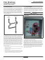
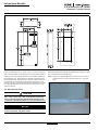
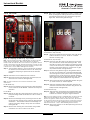
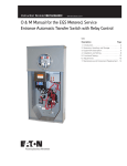
1
O & M Manual for the CHGEN
Automatic Transfer Switch
Instruction Booklet
New Information
Description
Page
Introduction . . . . . . . . . . . . . . . . . . . . . .
Receiving, Handling, and Storage . . . . . . .
Equipment Description. . . . . . . . . . . . . . .
Installation and Wiring . . . . . . . . . . . . . .
Functional Testing . . . . . . . . . . . . . . . . .
Maintenance and Component Replacement
Installing Optional Components. . . . . . . . .
IB01602014E
.
.
.
.
.
.
.
.
.
.
.
.
.
.
.
.
.
.
.
.
.
.
.
.
.
.
.
.
.
.
.
.
.
.
.
.
.
.
.
.
.
.
.
.
.
.
.
.
.
.
.
.
.
.
.
.
.
.
.
.
.
.
.
.
.
.
.
.
.
.
.
.
.
.
.
.
.
.
.
.
.
.
.
.
. 2
. 6
. 7
. 8
.14
.15
.32
For more information visit: www.eaton.com
Instructional Booklet
Page 2
Effective: January 2008
O & M Manual for the CHGEN
Automatic Transfer Switch
SECTION 1: INTRODUCTION
WARNING
READ AND UNDERSTAND THE INSTRUCTIONS CONTAINED HEREINAFTER BEFORE ATTEMPTING TO UNPACK, ASSEMBLE, OPERATE,
OR MAINTAIN THIS EQUIPMENT.
HAZARDOUS VOLTAGES ARE PRESENT INSIDE TRANSFER SWITCH
ENCLOSURES THAT CAN CAUSE DEATH OR SEVERE PERSONAL
INJURY. FOLLOW PROPER INSTALLATION, OPERATION, AND MAINTENANCE PROCEDURES TO AVOID THESE VOLTAGES.
THE TRANSFER SWITCH EQUIPMENT COVERED BY THIS INSTRUCTION BOOK IS DESIGNED AND TESTED TO OPERATE WITHIN ITS
NAMEPLATE RATINGS. OPERATION OUTSIDE OF THESE RATINGS
MAY CAUSE THE EQUIPMENT TO FAIL RESULTING IN DEATH, SERIOUS BODILY INJURY, AND/OR PROPERTY DAMAGE. ALL RESPONSIBLE PERSONNEL SHOULD LOCATE THE DOOR MOUNTED
EQUIPMENT NAMEPLATE AND BE FAMILIAR WITH THE INFORMATION PROVIDED ON THE NAMEPLATE. A TYPICAL EQUIPMENT
NAMEPLATE IS SHOWN IN FIGURE 1.
1.1 Preliminary Comments and Safety Precautions
This technical document is intended to cover most aspects associated with the installation, application, operation, and maintenance
of the CHGEN Automatic Transfer Switch (ATS). It is provided as
a guide for authorized and qualified personnel only. Please refer to
the specific WARNING and CAUTION in Section 1.1.2 before proceeding. If further information is required by the purchaser regarding a particular installation, application, or maintenance activity,
please contact an authorized Eaton sales representative or the
installing contractor.
1.1.1 Warranty and Liability Information
No warranties, expressed or implied, including warranties of fitness for a particular purpose of merchantability, or warranties arising from course of dealing or usage of trade, are made regarding
the information, recommendations, and descriptions contained
herein. In no event will Eaton be responsible to the purchaser or
user in contract, in tort (including negligence), strict liability, or
otherwise for any special, indirect, incidental or consequential
damage, or loss whatsoever, including but not limited to damage
or loss of use of equipment, plant or power system, cost of capital, loss of power, additional expenses in the use of existing
power facilities, or claims against the purchaser or user by its customers resulting from the use of the information and descriptions
contained herein.
1.1.2 Safety Precautions
All safety codes, standards, and/or regulations must be strictly
observed in the installation, application, operation, and maintenance of this device.
WARNING
Figure 1. Typical Automatic Transfer Switch Equipment
Nameplate.
All possible contingencies that may arise during installation, operation, or maintenance, and all details and variations of this equipment do not purport to be covered by these instructions. If
further information is required by the purchaser regarding a particular installation, application, or maintenance activity, please contact an authorized Eaton sales representative or the installing
contractor.
THE WARNINGS AND CAUTIONS INCLUDED AS PART OF THE PROCEDURAL STEPS IN THIS DOCUMENT ARE FOR PERSONAL SAFETY
AND PROTECTION OF EQUIPMENT FROM DAMAGE. AN EXAMPLE
OF A TYPICAL WARNING LABEL HEADING IS SHOWN ABOVE TO
FAMILIARIZE PERSONNEL WITH THE STYLE OF PRESENTATION.
THIS WILL HELP TO ENSURE THAT PERSONNEL ARE ALERT TO
WARNINGS, WHICH APPEAR THROUGHOUT THE DOCUMENT. IN
ADDITION, CAUTIONS ARE ALL UPPER CASE AND BOLDFACE.
CAUTION
READ AND UNDERSTAND THE MATERIAL PRESENTED IN THIS DOCUMENT BEFORE ATTEMPTING INSTALLATION, APPLICATION, OPERATION, OR MAINTENANCE OF THE EQUIPMENT. IN ADDITION,
ONLY QUALIFIED PERSONS SHOULD BE PERMITTED TO PERFORM
ANY WORK ASSOCIATED WITH THE EQUIPMENT. ANY WIRING
INSTRUCTIONS PRESENTED IN THIS DOCUMENT MUST BE FOLLOWED PRECISELY. FAILURE TO DO SO COULD CAUSE PERMANENT EQUIPMENT DAMAGE.
For more information visit: www.eaton.com
IB01602014E
Instructional Booklet
Effective: January 2008
O & M Manual for the CHGEN
Automatic Transfer Switch
1.2 General Information
ATSs are used to protect critical electrical loads against loss of
power. The load’s utility (Source 1) power source is backed up by
a generator (Source 2) power source. An ATS is connected to
both the utility and generator power sources and supplies the load
with power from one of these two sources. In the event that
power is lost from the utility power source, the ATS transfers the
load to the generator power source. Once the utility power is
restored, the load is automatically transferred back to the utility
power source (Figure 2).
Utility
(Source 1)
Generator
(Source 2)
Page 3
1.2.1 Design Configuration
The Eaton ATS is a rugged, compact design that utilizes contactors to transfer essential loads from one power source to another
(see Figure 3). The ATS contains suitable mechanical and electrical interlock switches to eliminate the possibility of connecting the
utility service to the generator output. In addition, a manual override lever is provided for the transfer function.
WARNING
DO NOT MANUALLY TRANSFER THE SWITCH WHILE
UNDER LOAD.
.
Load
Figure 2. Typical Load Transfer Switch (Contactor) Schematic.
An intelligence system initiates the transfer when the utility power
source fails or falls below a preset voltage. An engine start is
then initiated and the ATS transfers to the generator power source
when sufficient generator voltage is available. When the utility
power source is restored, the ATS automatically transfers back
and the generator will shut down after a time delay. In the event
the utility power source fails and the generator power source
does not appear, the ATS remains connected to the utility power
source until the generator power source does appear. Conversely,
if connected to the generator power source and the generator
power source fails while the utility power source is still unavailable, the ATS remains connected to the generator power source.
ATSs automatically perform the transfer function, and include
three basic elements.
1. Main contacts to connect and disconnect the load to and from
the source of power.
Figure 3. CHGEN ATS (100 A).
1.2.2 Optional Service Entrance Feature
The ATS can be ordered in either a standard or service entrance
(SE) configuration. When ordered as an SE, integral overcurrent
protection is built into the switch. Therefore, the ATS can be
installed at the point of service entrance without the need for an
upstream disconnect device. Also the switch comes with a generator breaker on the generator (Source 2) side of the contactor (see
Figure 5a and 5b).The generator breaker can be switched OFF to
prevent the transfer of power from the generator source to the
load, if the service entrance breaker is switched OFF manually
(Not an overload condition).
2. Solenoids to make the transfer of the main contacts from
source to source.
3. Intelligence/supervisory circuits to constantly monitor the condition of the power sources and thus provide the intelligence
necessary for the switch and related circuit operation.
IB01602014E
For more information visit: www.eaton.com
Instructional Booklet
Page 4
Effective: January 2008
O & M Manual for the CHGEN
Automatic Transfer Switch
Figure 4. A Standard ATS.
Figure 5b. An SE ATS 200A.
Figure 5a. An SE ATS 100A.
For more information visit: www.eaton.com
IB01602014E
Instructional Booklet
Effective: January 2008
O & M Manual for the CHGEN
Automatic Transfer Switch
The benefits of the SE configuration are:
• Combined service disconnect and over-current protection in the
ATS reduces the overall equipment and installation costs.
• Fewer components and power connections reduce maintenance
requirements.
Page 5
LOAD SHED
1.2.3 Optional TVSS Surge Protection
Transient voltage surge suppressor (TVSS) surge protection is
available as an optional feature on all CHGEN ATSs. If you have
ordered an optional TVSS, the TVSS will be included with the
CHGEN ATS, but it is up to the installer to mount and wire the
TVSS and associated fuse block. See examples in Figures 6 and 7,
and see Sections 7.1 and 7.2 for complete instruction for installing the optional TVSS.
1.2.4 Optional Load Shed
Four sets of contacts are available and can be used to control
large connected loads on the generator (i.e. air conditioners, hot
tubs, etc.). See Section 7.5 for complete instructions for installing
the optional load shed.
TVSS
TVSS
Figure 7. TVSS Mounted to the Outside of a Standard Enclosure.
LOAD SHED
1.2.5 Optional Telephone and Cable Surge Protection
The telephone line surge protection feature offers 4-pair telephone
line protection. The feature ships loose for customer mounting
convenience. See Section 7.3.
The TV and satellite cable surge protection feature offers two (2)
coaxial line protection (cable/satellite TV). The feature ships loose
for customer mounting convenience. See Section 7.4.
Figure 6. TVSS and Load Shed Mounted in an SE Enclosure.
IB01602014E
For more information visit: www.eaton.com
Instructional Booklet
Page 6
Effective: January 2008
O & M Manual for the CHGEN
Automatic Transfer Switch
1.3 Transfer Switch Catalog Number Identification
ATS equipment catalog numbers provide a significant amount of
relevant information pertaining to a specific piece of equipment.
The Catalog Number Identification Table (see Table 1) provides
the required interpretation information. An example is offered to
initially simplify the process.
The catalog number CHGEN100ATSRSE describes an ATS.
Table 1. ATS Catalog Number Explanation.
POSITIONS 1-2
POSITION 3-5
POSITION 6-8
Manufacturer
Type
Ampere Rating
Generator GEN
100 A – 100
200 A – 200
Cutler-Hammer
CH
POSITION 9-11
POSITION 12
Type
Enclosure
POSITION 13-14
Service Entrance
Automatic ATS
Transfer
Switch
NEMA 3R R
Standard Blank
Service EntranceSE
1.4 Environmental and Operational Conditions
Normally, an ATS is applied indoors in an electrical equipment
room. It can also be used for normal outdoor applications (with a
Nema 3R enclosure) where the equipment is subject to falling rain,
freezing temperatures, and 95% humidity (non-condensing). The
ambient temperature range for operation is between -20 and 70°C
(-4 and 158°F).
Seismic
With proper installation, these transfer switches have a seismic
capability which exceeds the worst case Zone 4 required levels
per both the Uniform Building Code and the California Building
Code.
SECTION 2: RECEIVING, HANDLING, AND
STORAGE
2.1 Receiving
Every effort is made to ensure that the ATS equipment arrives at
its destination undamaged and ready for installation. The packing
is designed to protect the internal components as well as the
enclosure. Care should be exercised, however, to protect the
equipment from impact at all times. Do not remove the protective
packaging until the equipment is at the installation site and ready
to be installed.
When the ATS equipment reaches its destination, the customer
should inspect the shipping container for any obvious signs of
rough handling and/or external damage that occurred during transportation. Record any external and internal damage for reporting
to the transportation carrier and to the Eaton sales representative,
once a thorough inspection is complete. All claims should be as
specific as possible and include the Shop Order and General Order
numbers.
A shipping label affixed to the shipping container includes a variety of equipment and customer information, such as General
Order and Customer numbers. Make certain that this information
matches the other shipping paper information.
Each ATS enclosure is packaged in its own box. Heavy-duty cardboard sides surround the enclosure. Do not discard the packing
material until the equipment is ready for installation.
Once the top packaging is removed from the shipment, the enclosure door can be opened. A plastic bag of documents will be
found in the enclosure. Important documents, such as wiring diagrams and appropriate instruction leaflets are enclosed within the
bag and should be filed in a safe place.
2.2 Handling
As previously mentioned, ATS equipment is packaged in its own
box. Protect the equipment from impact at all times and do not
double stack. Once the equipment is at the installation site and
ready to be installed, the packaging material can be removed.
Refer to Section 4 of this manual for specific installation instructions.
2.3 Storage
Although well packaged, this equipment is not suitable for outdoor
storage. The equipment warranty will not be applicable if there is
evidence of outdoor storage. If the equipment is to be stored
indoors for any period of time, it should be stored with its protective packaging material in place. Protect the equipment at all
times from excessive moisture, construction dirt, corrosive conditions, and other contaminants. It is strongly suggested that the
package-protected equipment be stored in a climate-controlled
environment of -20 to 65°C (-4 to 149°F), with a relative humidity of 80% or less. Do not, under any circumstance, stack other
equipment on top of an ATS equipment enclosure, whether packaged or not.
For more information visit: www.eaton.com
IB01602014E
Instructional Booklet
Effective: January 2008
O & M Manual for the CHGEN
Automatic Transfer Switch
SECTION 3: EQUIPMENT DESCRIPTION
3.1 Introduction
The Eaton ATS is assembled and tested at the factory. It is
designed to be used in conjunction with standby power distribution equipment to provide an alternate source of power to critical
circuits in the event that the primary power source is interrupted.
This ATS monitors both utility (Source 1) and generator (Source 2)
power sources and automatically transfers critical load circuits
between the two sources, depending on which source is available.
The utility power source is preferred and will remain connected to
the switch if it is available.
3.2 Features
The following section describes the standard features in the
CHGEN ATS.
Note: The time delays are not adjustable.
1. Time Delay Normal (Utility) to Emergency (Generator) (TDNE)
This feature delays the transfer from the utility (Source 1)
power source to the generator (Source 2) power source in order
to override momentary utility power source outages and/or
fluctuations. Timing begins when the generator power source
becomes available. Should the utility power source fail, the
generator will start up after its time delay. The TDNE timer is
set for 50 seconds.
2. Time Delay on Engine Starting (TDES)
This feature delays initiation of the generator engine start circuit in order to override momentary utility (Source 1) power
source outages and/or fluctuations. It does not affect the ability of the transfer switch to transfer from the utility power
source to the generator (Source 2) power source. The TDES
timer is dependent on the generator.
3. Time Delay Emergency (Generator) to Normal (Utility) (TDEN)
This feature delays the transfer from the generator (Source 2)
power source to the utility (Source 1) power source to allow
the utility power source to stabilize before the transfer is initiated. Timing begins when the utility power source becomes
available. If the generator power source fails during timing, the
time delay is overridden and an immediate transfer to the utility
power source will occur. The TDEN timer is set for 10 seconds.
Failsafe
Failsafe refers to the condition whereby the ATS is connected
to the generator (Source 2) power source. In the event that the
generator power source fails and the utility (Source 1) power
source is available, an immediate retransfer to the utility power
source will occur.
4. Time Delay Engine Cool-off (TDEC)
This feature allows the generator engine to run after the ATS
returns to the utility (Source 1) power source without load.
The generator will run for its time delay.
Page 7
5B. Undervoltage Sensing for Emergency (Generator) Source
This feature enables the logic to constantly monitor the generator (Source 2) power source. The logic prevents transfer
from the utility (Source 1) power source to the generator
power source until the generator power source has reached
an acceptable operating voltage and frequency. Dropout is
set at 80% of nominal voltage and pickup is set at 90% of
nominal voltage.
26. Undervoltage Sensing for Normal (Utility) Source
This feature enables the logic to constantly monitor the utility (Source 1) power source. The logic prevents transfer from
the generator (Source 2) power source to the utility power
source until the utility power source has reached an acceptable operating voltage. Dropout is set at 80% of nominal
voltage and pickup is set at 90% of nominal voltage.
3.3 Optional Features
The following is a list of optional features for the CHGEN ATS.
36. Load Shed
Four sets of contacts are available and can be used to control large connected loads on the generator (i.e. air conditioners, hot tubs, etc.).
37. Service Equipment Rated Transfer Switch
This feature provides the label ”Suitable for use as Service
Equipment” and the features necessary to meet the requirements for the label.
51H. CHSPULTRA
This feature provides a 70KA, 240/120VAC, 1 Ohm surge
device. It can be mounted on the Source 1 line. The feature
ships loose for customer mounting convenience.
51J. Telephone Surge Protection
The telephone line surge protection feature offers 4-pair telephone line protection. The feature ships loose for customer
mounting convenience.
51K.Cable Surge Protection
The TV and satellite cable surge protection feature offers 2
coaxial line protection (cable/satellite TV). The feature ships
loose for customer mounting convenience.
3.4 Standards
Eaton ATS equipment, enclosed in NEMA 3R enclosures, are listed
for application by UL. In addition, Eaton ATSs are listed in File
E38116 by Underwriters Laboratories, Inc. under Standard UL
1008. This standard covers the requirements for ATSs intended
for use in ordinary locations to provide lighting and power as follows:
a. In standby systems, in accordance with article 702 of the
National Electrical Code.
Eaton ATSs are available to meet NFPA 110 for standby power
systems.
Eaton ATS equipment are listed for application by CSA. In addition, Eaton ATSs are listed in the Legacy File LR96245 Master
Contract 163545 by Canadian Standards Association under Standard 22.2 #178-1978
IB01602014E
For more information visit: www.eaton.com
Instructional Booklet
Page 8
Effective: January 2008
O & M Manual for the CHGEN
Automatic Transfer Switch
SECTION 4: INSTALLATION AND WIRING
4.2 Mounting Location
4.1 General
Choose a location that offers a flat, rigid mounting surface capable of supporting the weight of the enclosed ATS equipment (see
Figure 8, 100 A Standard, Figure 9, 100 A SE, Figure 10, 200 A
Standard, or Figure 11, 200 A SE). Protect the transfer switch at
all times against excessive moisture, dust, dirt, lint, and corrosive
vapors.
Eaton ATSs are factory wired and tested. Installation requires solidly mounting the enclosed unit and connecting the power cables
and the auxiliary pilot circuits. Physical mounting procedures and
power cable connections are covered in this section.
Once a transfer switch is properly installed and wired, it should be
mechanically and electrically checked for proper installation and
operation. The procedures for these initial mechanical and electrical checks are outlined in Section 5 of this manual.
Figure 8. Dimensions and Plan View of Standard CHGEN Automatic Transfer Switch (in.) (100 A).
For more information visit: www.eaton.com
IB01602014E
Instructional Booklet
Effective: January 2008
O & M Manual for the CHGEN
Automatic Transfer Switch
Figure 9. Dimensions and Plan View of SE CHGEN Automatic Transfer Switch. (in.) (100 A).
Figure 10. Dimensions and Plan View of Standard CHGEN Automatic Transfer Switch (in.) (200 A).
IB01602014E
For more information visit: www.eaton.com
Page 9
Instructional Booklet
Page 10
Effective: January 2008
O & M Manual for the CHGEN
Automatic Transfer Switch
Figure 11. Dimensions and Plan View of SE CHGEN Automatic Transfer Switch (in.) (200 A).
Check to ensure there are no pipes, wires, or other mounting hazards in the immediate mounting area that could create a problem.
With the enclosed ATS equipment unpacked and ready for mounting, proceed with the following steps.
Carefully remove all packing material from the ATS enclosure at
the installation site. Even though an equipment inspection was
performed when the equipment was received, make another careful inspection of the enclosure and the ATS mechanism as the
packing material is removed and the enclosure readied for mounting. Be especially alert for distorted metal, loose wires, or damaged components.
Step 1: Depress the padlockable catch at the bottom of the door
and slide the door downward (see Figure 12). Open the
door.
4.3 Mounting Procedure
CAUTION
EXTREME CARE SHOULD BE TAKEN TO PROTECT THE ATS FROM
DRILL CHIPS, FILINGS, AND OTHER CONTAMINANTS WHEN MAKING THE CABLE ENTRY HOLES AND MOUNTING THE ENCLOSURE
TO PREVENT COMPONENT DAMAGE OR A FUTURE MALFUNCTION.
NOTICE
THE INSTALLATION MUST FULLY COMPLY WITH ALL APPLICABLE
CODES, STANDARDS, AND REGULATIONS.
Figure 12. Location of the Door Latch.
For more information visit: www.eaton.com
IB01602014E
Instructional Booklet
Effective: January 2008
O & M Manual for the CHGEN
Automatic Transfer Switch
Step 2: Use the knockouts for cable entry and control wiring.
NOTICE
GENERATOR CONTROL CIRCUIT WIRING MUST BE RUN SEPARATE
FROM POWER CABLES.
Step 3: Mount the switch to a rigid structure as close to the electrical loads as possible.
4.4 Power Cable Connection
Page 11
Step 1: Connect cables as follows (see Figures 13 and 14, and
Table 2):
• The utility (Source 1) power cables to the utility lugs or SE
breaker if installed;
• The generator (Source 2) power cables to the generator lugs or
generator breaker lugs (for SE only);
• The customer load cables to the main distribution panel (load)
lugs;
• The neutral cables to the neutral bar; and
• The ground wires to the ground bar.
UTILITY
LUGS
WARNING
POWER CONDUCTORS MAY HAVE VOLTAGE PRESENT THAT CAN
CAUSE SEVERE PERSONAL INJURY OR DEATH. DE-ENERGIZE ALL
POWER OR CONTROL CIRCUIT CONDUCTORS TO BE CONNECTED
TO THE ATS EQUIPMENT BEFORE BEGINNING TO WORK WITH THE
CONDUCTORS AND/OR TERMINATING THEM TO THE EQUIPMENT.
CAUTION
TO HELP PREVENT COMPONENT DAMAGE OR FUTURE MALFUNCTIONS, USE EXTREME CARE TO KEEP CONTAMINANTS OUT OF THE
ATS EQUIPMENT WHEN MAKING THE POWER CABLE CONNECTIONS
Test all power cables prior to connection to the unit to ensure that
the conductors or cable insulation has not been damaged while
being pulled into position.
GENERATOR
LUGS
GENERATOR
Power cables are to be connected to solderless, screw type lugs
located on the automatic transfer switching devices. Verify that
the lugs supplied will accommodate the power cables being used.
Also verify that the cables comply with all local electrical codes.
Standard ATS equipment, as supplied from the factory, will
accommodate the wire sizes shown in Table 2.
LOAD LUGS
Table 2. Wire Sizes for ATSs.
TRANSFER SWITCH
AMP RATING
CONTACTOR WIRE
SIZE RANGE
NUMBER OF CABLES
PER PHASE
100
#14 – 2/0
1
200
#6 – 290 KCMIL
1
Figure 13. Cable Connection Locations (100 A).
Carefully strip the insulation from the power cables to avoid nicking or ringing of the conductor strands. Prepare the stripped conductor termination end by cleaning it with a wire brush. If
aluminum conductors are used, apply an appropriate joint compound to the clean conductor surface area.
CAUTION
IMPROPER POWER CABLE CONNECTIONS CAN CAUSE EXCESSIVE
HEAT AND SUBSEQUENT EQUIPMENT FAILURE.
Note: Tighten the cable lugs to the torque identified on the label affixed to
the unit’s door.
IB01602014E
For more information visit: www.eaton.com
Instructional Booklet
Page 12
Effective: January 2008
O & M Manual for the CHGEN
Automatic Transfer Switch
UTILITY LUGS
4.5 Wiring
WARNING
POWER CONDUCTORS AND SENSING WIRES MAY HAVE VOLTAGE
PRESENT THAT CAN CAUSE SEVERE PERSONAL INJURY OR
DEATH. DE-ENERGIZE ALL POWER OR CONTROL CIRCUIT CONDUCTORS BEFORE BEGINNING TO PERFORM ANY WIRING ACTIVITY TO
OR WITHIN THE ATS EQUIPMENT.
CAUTION
CHECK THE ATS EQUIPMENT NAMEPLATE FOR RATED VOLTAGE.
IT SHOULD BE THE SAME AS THE UTILITY (SOURCE 1) AND GENERATOR (SOURCE 2) LINE VOLTAGES. OPERATING THE EQUIPMENT
ON IMPROPER VOLTAGE CAN CAUSE EQUIPMENT DAMAGE.
4.6 Installation
GENERATOR
LUGS
LOAD LUGS
In a typical installation for critical loads (see Figure 16), the ATS
(1) and the generator (2) are connected to the power supply. The
ATS (1) and emergency distribution panel (3) receive utility
(Source 1) power from a dedicated breaker in the utility service
panel (4). The ATS and emergency panel receive generator
(Source 2) power from the generator (2). Power from the utility
feeds the utility panel.
Figure 14. Cable Connection Locations (200 A).
Step 2: The utility sensing fuse block is located at the bottom center of the power panel and is used to supply 24O Vac to
the generator (See Figure 15). See Section 4.7 for more
detailed information on connecting these inputs.
Figure 16. Typical Installation of a Light Commercial ATS.
The switch (1) and generator (2) are connected to the power supply. The ATS is located between the emergency distribution (3)
and the utility panel (4).
When the utility power fails, the ATS will sense the failure, the
generator will start, and when sufficient generator voltage is available, the ATS will switch all loads to the emergency panel. All
emergency loads will receive power from the generator. A line
breaker is required between the generator power source and the
transfer switch (see Figure 17). When utility power returns, the
ATS will switch all power back to the utility panel and the generator will shut down.
Figure 15. Utility Sensing Fuse Block Location.
Step 3: Tighten all cables and wiring to specifications.
For more information visit: www.eaton.com
IB01602014E
Instructional Booklet
Effective: January 2008
O & M Manual for the CHGEN
Automatic Transfer Switch
Page 13
Figure 19. Diagram of a Typical Installation (All Loads).
4.7 Utility Sensing Fuse Block Connection
The generator’s 240 Vac utility sensing fuse block is located at
the bottom center of the power panel of the ATS (Figure 15).
Prior to making the sensing inputs connection to the ATS, set the
generator control selector switch to the OFF position to prevent
an unwanted engine start.
Figure 17. Diagram of a Typical Installation (Critical Loads Only).
In addition, another typical installation for loads can be considered
(see Figure 18). Refer to Figure 19 for a loads connection diagram.
Connect the sensing wires to the fuse block. These wires should
be connected to the side of the fuse block with no existing wires.
See Section 6 (Figure 20) for the wiring diagram.
4.8 Preliminary Checks
After the ATS enclosure is installed and power cables are connected to the equipment, thoroughly inspect the unit to ensure
that no tools were left inside and that the cabinet is free of debris.
If necessary, use a vacuum cleaner to remove any and all construction or installation debris from the equipment.
Read and understand all labels on the equipment. Review and
understand the wiring diagrams supplied with the equipment.
Note any optional accessories that may have been furnished with
this unit and review their operation.
Verify that the phase-to-phase line voltages of both the utility
(Source 1) and generator (Source 2) power sources are the same
and that they match the rated voltage as indicated on the ATS ratings label.
CAUTION
Figure 18. Typical Installation of a Light Commercial ATS.
The switch (1) and generator (2) are connected to the power
supply. The ATS is located between the utility and the loads.
IB01602014E
SEVERE EQUIPMENT DAMAGE CAN RESULT IF THE UNIT IS NOT
APPLIED AT PROPER VOLTAGE. DO NOT ENERGIZE THE EQUIPMENT IF THE SUPPLY VOLTAGES DO NOT MATCH EQUIPMENT
RATINGS LABEL.
For more information visit: www.eaton.com
Instructional Booklet
Page 14
Effective: January 2008
O & M Manual for the CHGEN
Automatic Transfer Switch
SECTION 5: FUNCTIONAL TESTING
WARNING
YOU ARE READY TO ENERGIZE THE EQUIPMENT. VOLTAGES
WITHIN THE ENCLOSURE ARE CAPABLE OF CAUSING SEVERE PERSONAL INJURY OR DEATH. USE EXTREME CAUTION TO AVOID
CONTACT WITH ENERGIZED EQUIPMENT.
5.1 Preliminary Checks
Step 1: Check all loads connected to the ATS to ensure that they
are ready to be energized.
5.2 Energize the Switch
Step 4: Using a voltmeter, measure the line-to-line and line-to-neutral voltages across the generator line terminals to ensure
that the generator emergency voltage is correct. If necessary, make adjustments to the voltage regulator on the
generator according to the manufacturer’s recommendations to correct any voltage deviations. The ATS will only
respond to the correct voltage from the generator power
source.
Step 5: Close the utility breaker described in Step 1 of
Section 5.2.
Step 6: The ATS Time Delay Emergency (Generator) to Normal
(Utility) (TDEN) timer will begin timing, and the solenoid
will engage and automatically switch from the GENERATOR to the UTILITY position and the generator will shut
down.
Step 1: Close the upstream utility (Source 1) power source
breaker or switch to connect the ATS to the utility power
source voltage.
Step 2: If the ATS unit is not already in the UTILITY position, the
solenoid will engage and the contactor will automatically
switch to the UTILITY position.
Step 3: Using a voltmeter, measure the line-to-line and the line-toneutral voltages across the utility line terminals to ensure
the utility voltage is correct.
WARNING
CONTACT WITH ENERGIZED COMPONENTS WILL CAUSE ELECTRICAL SHOCK CAPABLE OF PRODUCING SEVERE PERSONAL INJURY
OR DEATH. USE EXTREME CAUTION TO AVOID CONTACT WITH
ENERGIZED COMPONENTS WHEN USING A METER FOR VOLTAGE
CHECKS.
Step 4: Position the generator control selector switch, located on
the standby generator, to the AUTO position.
Step 5: Close the upstream generator (Source 2) power source
breaker or switch to connect the ATS to the generator
power supply source.
5.3 Operational Checks
Step 1: Open the upstream utility (Source 1) breaker
originally closed in Step 1 of Section 5.2.
NOTICE
THIS WILL SIMULATE AN INTERRUPTION OF THE UTILITY (SOURCE
1) POWER SOURCE.
Step 2: After a time delay, the standby generator engine will start.
Step 3: The ATS Time Delay Normal (Utility) to Emergency (Generator) (TDNE) will begin to time after the generator engine
begins to run. After time out, the solenoid will engage and
the contactor will automatically switch from the UTILITY
to the GENERATOR (Source 2) position.
For more information visit: www.eaton.com
IB01602014E
Instructional Booklet
Effective: January 2008
O & M Manual for the CHGEN
Automatic Transfer Switch
SECTION 6: MAINTENANCE AND
COMPONENT REPLACEMENT
6.1 Introduction
WARNING
HIGH VOLTAGES ARE PRESENT IN AND AROUND TRANSFER
SWITCH EQUIPMENT. BEFORE INSPECTING OR MAINTAINING THIS
EQUIPMENT, DISCONNECT THE LINE POWER FROM THE EQUIPMENT BEING SERVICED BY OPENING AND LOCKING OUT, IF POSSIBLE, THE NEXT HIGHEST DISCONNECT DEVICE. FAILURE TO
FOLLOW THIS PROCEDURE COULD CAUSE SEVERE PERSONAL
INJURY AND/OR DEATH.
In general, ATS equipment is designed to be relatively maintenance free under normal usage. However, because of the variability of application conditions and the importance placed on
dependable operation by this type of equipment, inspection and
maintenance checks should be made on a regularly scheduled
basis. Since equipment maintenance will consist mainly of keeping the equipment clean, the frequency of maintenance will
depend, to a large extent, on the cleanliness of its surroundings.
If a significant amount of dust or foreign matter is present, a more
frequent maintenance schedule should be followed.
It is suggested that visual inspections of the equipment be made
on a regular basis, not just during regularly scheduled periods.
Always be alert for an accumulation of dirt in and around the
structure, loose parts and/or hardware, cracks and/or discoloration
to insulation, and damaged or discolored components.
Figure 20 is the wiring diagram for the CHGEN ATS switch.
Note: Only qualified and experienced personnel should attempt any diagnostic work using this diagram.
Figure 20. Wiring Diagram for the CHGEN ATS.
IB01602014E
Page 15
For more information visit: www.eaton.com
Instructional Booklet
Page 16
Effective: January 2008
O & M Manual for the CHGEN
Automatic Transfer Switch
6.2 Procedures
A suggested maintenance procedure to be followed is outlined in Table 3.
Table 3. Recommended Periodic Maintenance Procedures
STEP
ACTION
a. Make the transfer switch equipment safe for inspection and/or maintenance.
Disconnect the line power from the equipment being serviced by opening next highest disconnect
device. Make certain that any accessory control power is switched off.
b. Inspect the structure area for safety hazards or potential maintenance problems.
Inspect the area, especially where the contactor is installed, for any safety hazards, including personal safety and fire hazards. Exposure to certain chemical vapors can cause deterioration of the
electrical connections.
Inspect for accumulated dirt, loose hardware, or physical damage.
Examine the primary insulation for evidence of cracking or overheating. Overheating will show as
discoloration, melting, or blistering of the conductor insulation, or as pitting or melting of the conductor surfaces due to arcing.
Inspect the secondary control connections for damage, and control wiring for insulation integrity.
c. Inspect the contactor for dust, dirt, soot, grease, moisture, or corrosion.
Remove dust, dirt, soot, grease, moisture, and corrosion contamination from the surface of the
switching device using a dry, soft lint-free cloth, dry soft bristle brush, and vacuum cleaner. Do
not blow debris into the contactor. If contamination is found, look for the source and fix the problem.
d. Check for material integrity, uneven wear, discoloration, or loose hardware.
Severe material cracking will require replacement and loose hardware will need to be tightened.
e. Check the terminals and connectors for looseness or signs of overheating.
Overheating will show as discoloration, melting, or blistering of the conductor insulation.
Connections that do not have signs of looseness or overheating should not be disturbed.
f. Exercise the contactor if it is not often exercised while in operation. This will permit the wiping If a switching device is used for frequent switching during normal operation, this step can be disaction by the contacts.
regarded.
g. Return the transfer switch equipment to service.
Make certain all barriers are in place and the door is closed. Re-apply generator (Source 2) and
utility (Source 1) power.
For more information visit: www.eaton.com
IB01602014E
Instructional Booklet
Effective: January 2008
O & M Manual for the CHGEN
Automatic Transfer Switch
6.3 Maintenance Log
DATE
ACTION
Example: 01/01/05
Inspected and cleaned.
IB01602014E
For more information visit: www.eaton.com
Page 17
Instructional Booklet
Page 18
Effective: January 2008
O & M Manual for the CHGEN
Automatic Transfer Switch
6.4 Component Replacement
Certain components within the ATS are field replaceable. Figure
21 identifies the field replaceable parts. Table 4 lists the part
numbers to use when ordering replacement components. To order
replacement components, contact an authorized Eaton sales representative.
GENERATOR
CONTROLLER BOARD
CONTACTOR
NEUTRAL
BAR
UTILITY LUGS
HARNESS
SERVICE
ENTRANCE
BREAKER
NEUTRAL BAR
GROUND BAR
GENERATOR
LUGS
GENERATOR
CONTROLLER
BOARD
UTILITY
LUGS
CONTACTOR
GENERATOR
BREAKER
LUGS
LOAD LUGS
HARNESS
GENERATOR
LUGS
GENERATOR
BREAKER
LOAD LUGS
GROUND
BAR
BASE PLATE
BASE PLATE
Figure 21. Field Replaceable Components (Left 100 A Standard, Right 200 A SE).
Table 4. Field Replaceable Components
COMPONENT
PART NUMBER
ATS MODEL
Contactor
8160A99G51
100 A
Contactor
8160A99G52
200 A
Generator Controller Board
8160A99G33
100 & 200 A
Ground Bar
8160A99G55
100 & 200 A
Load Shed (Option)
8160A99G36
100 & 200 A
Lugs
8160A99G56
100 A
Lugs
8160A99G57
200 A
Neutral Bar
8160A99G53
100 A
Neutral Bar
8160A99G54
200 A
Service Entrance Breaker
8160A99G41
100 A
Service Entrance Breaker
8160A99G42
200 A
Service Entrance Cover
8160A99G45
100 & 200 A
Service Entrance Lugs
8160A99G43
100A
Service Entrance Lugs
8160A99G44
200A
Generator Breaker (SE Only Option)
8160A99G41
100A
Generator Breaker (SE Only Option)
8160A99G42
200A
Generator Breaker Lugs (SE Only Option)
8160A99G43
100A
Generator Breaker Lugs (SE Only Option)
8160A99G44
200A
SurgTel
8160A99G48
100 & 200 A
SurgCable
8160A99G49
100 & 200 A
TVSS (Internal, SE Only-Option)
8160A99G46
100 & 200 A
TVSS (External, Standard or SE-Option)
8160A99G47
100 & 200 A
Wiring Harness1
8160A99G34
100 & 200 A
Note: 1 When replacing the wiring harness on the 100 A ATS, the flag must be cut off the one white wire and replaced with the appropriate size ring terminal.
For more information visit: www.eaton.com
IB01602014E
Instructional Booklet
Effective: January 2008
O & M Manual for the CHGEN
Automatic Transfer Switch
Page 19
.
WARNING
HIGH VOLTAGES ARE PRESENT IN AND AROUND TRANSFER
SWITCH EQUIPMENT. BEFORE ATTEMPTING TO REPLACE ANY
COMPONENT, DISCONNECT THE LINE POWER FROM THE EQUIPMENT BEING SERVICED BY OPENING AND LOCKING OUT, IF POSSIBLE, THE NEXT HIGHEST DISCONNECT DEVICE. FAILURE TO
FOLLOW THIS PROCEDURE COULD CAUSE SEVERE PERSONAL
INJURY AND/OR DEATH.
ALWAYS TURN THE UTILITY (SOURCE 1) POWER OFF AND TURN
THE GENERATOR (SOURCE 2) CONTROL SELECTOR SWITCH TO
THE “OFF” POSITION BEFORE ATTEMPTING TO REPLACE ANY COMPONENTS.
NOTICE
APPLY UTILITY (SOURCE 1) POWER AND PLACE THE GENERATOR
CONTROL SELECTOR SWITCH IN THE “AUTO” POSITION AFTER THE
COMPONENT HAS BEEN REPLACED. TEST THE SYSTEM FOR
PROPER FUNCTIONALITY.
Figure 23. Generator Controller Board as Mounted in a Standard
100 A CHGEN ATS.
6.4.1 Component Replacement Instructions
6.4.1.1 100 A and 200 A Controller Board
Figure 22. Generator Controller Board Installed in the CHGEN
ATS.
Step 1: Turn the utility (Source 1) power off and turn the generator (Source 2) control selector switch to the “OFF” position before attempting to replace the generator controller
board.
Step 2: Note the orientation of the generator controller board as it
was mounted to the base plate at the factory (see Figures
23 and 24)
IB01602014E
Figure 24. Generator Controller Board as Mounted in a Standard
200 A, 100 A SE, and 200 A SE CHGEN ATSs.
Step 3: Disconnect the Neutral, N1, 1, N Coil, N Aux. N.C., E
Aux. N.C., E Coil, and E2 female flag connectors from the
generator controller board (Refer to the wiring diagram in
Figure 20 for connection locations on the generator controller board) (see Figure 25).
Note: All wires connected to the generator controller board are labeled to
ease identification.
For more information visit: www.eaton.com
Instructional Booklet
Page 20
Effective: January 2008
O & M Manual for the CHGEN
Automatic Transfer Switch
6.4.1.2 100 A Neutral Bar
Note: The 100 A ground and neutral bars are the same. Refer to
Figure 26 for the correct location.
N2
N1
N COIL
N AUX.
NEUTRAL
NEUTRAL BAR
E2
E COIL
E AUX.
Figure 25. Wires to Disconnect from the Generator Controller
Board.
Step 4: Remove the two (2) screws securing the generator controller board to the base plate using a blade screwdriver.
Remove the generator controller board.
GROUND BAR
Figure 26. 100 A Neutral Bar.
Step 5: Orient the new generator controller board as per the original installation then align the controller board with the
existing holes in the base plate. Secure the new generator controller board to the base plate using the hardware
supplied (see Figure 23 or 24).
Step 1: Turn the utility (Source 1) power off and turn the generator (Source 2) control selector switch to the “OFF” position before attempting to replace the neutral bar.
Step 6: Connect the Neutral, N1, N2, N Coil, N Aux. N.C., E Aux.
N.C., E Coil, and E2 female flag connectors to the new
generator controller board (Refer to the wiring diagram in
Figure 20 for connection locations on the generator controller board) (see Figure 25).
Step 3: If the neutral bar has been grounded, remove the 1.5 in.
screw that grounds the neutral bar to the base plate (see
Instruction Leaflet supplied with the grounding kit for
more information).
Step 7: Apply utility (Source 1) power and place the generator
control selector switch in the “AUTO” position after the
generator controller board has been replaced. Test the
system for proper functionality.
Step 2: Disconnect all wire cables from the neutral bar.
Step 4: Remove the screw in the black base using a blade screwdriver or 0.25 in. socket or nut driver. Remove the neutral bar (see Figure 27).
SCREW
Figure 27. Replacing the 100 A Neutral Bar.
Step 5: Remove the screw securing the white wire to the neutral
bar using a blade screwdriver or 0.25 in. socket or nut
driver.
Step 6: Attach the white wire to the new neutral bar using the
hardware supplied.
Step 7: Mount the neutral bar to the base plate using the hardware supplied.
For more information visit: www.eaton.com
IB01602014E
Instructional Booklet
Effective: January 2008
O & M Manual for the CHGEN
Automatic Transfer Switch
Step 8: If the neutral bar being replaced was grounded, use the
1.5 in. screw removed in Step 3 to ground the neutral
bar to the base plate (see Instruction Leaflet supplied
with the grounding kit for more information).
Step 9: Reconnect all wire cables to the neutral bar.
Step 10: Apply utility (Source 1) power and place the generator
control selector switch in the “AUTO” position after the
neutral bar has been replaced. Test the system for
proper functionality.
6.4.1.3 200 A Neutral Bar
Step 1: Turn the utility (Source 1) power off and turn the generator (Source 2) control selector switch to the “OFF” position before attempting to replace the SE neutral bar.
Step 2: Disconnect all wire cables from the neutral bar.
Page 21
Step 9: Reconnect all wire cables to the neutral bar.
Step 10: Apply utility (Source 1) power and place the generator
control selector switch in the “AUTO” position after the
SE neutral bar has been replaced. Test the system for
proper functionality.
6.4.1.4 Ground Bar
Note: The 100 A ground and neutral bars are the same. Refer to
Figure 26 for the correct location.
Step 1: Turn the utility (Source 1) power off and turn the generator (Source 2) control selector switch to the “OFF” position before attempting to replace the ground bar
Step 2: Disconnect all wire cables from the ground bar.
Step 3: Remove the 1.5 in. long screw at the top of the ground
bar (see Figure 29) using a Phillips screwdriver.
Step 3: Disconnect the flag from the wire terminal on the back of
the neutral bar (see Figure 28).
Step 4: If the neutral bar has been grounded, remove the 10-32
× 0.625 in. screw that grounds the neutral bar to the
base plate. Also remove the 1/4-20 × 0.50 in. bolt
securing the copper connector to the bottom of the neutral bar (see Instructional Leaflet supplied with the
grounding kit for more information).
Step 5: Remove the two (2) screws securing the neutral bar
bracket to the base plate (see Figure 28) using a blade
screwdriver or 0.25 in. socket or nut driver. Remove the
neutral bar.
SCREW
1.5 in.
PHILLIPS
SCREW
Figure 29. Replacing the Ground Bar.
Step 4: Remove the screw in the black base using a blade screwdriver or 0.25 in. socket or nut driver (see
Figure 29). Remove the ground bar.
FLAG
Step 5: Secure the new ground bar to the base plate using the
hardware supplied.
Step 6: Insert the 1.5 in. long screw into the top of the ground
bar. Use the hardware supplied if necessary.
Step 7: Reconnect all wire cables to the ground bar.
Step 8: Apply utility (Source 1) power and place the generator
control selector switch in the “AUTO” position after the
ground bar has been replaced. Test the system for proper
functionality.
SCREWS
Figure 28. Replacing the 200 A Neutral Bar.
Step 6: Secure the new neutral bar assembly to the base plate
using the hardware supplied.
Step 7: If the neutral bar being replaced was grounded, use the
copper connector, 10-32 × 0.625 in. screw, and 1/4-20
× 0.50 in. bolt removed in Step 4 to ground the neutral
bar to the base plate (see Instruction Leaflet supplied with
the grounding kit for more information).
Step 8: Connect the flag to the wire terminal on the back of the
neutral bar.
IB01602014E
For more information visit: www.eaton.com
Instructional Booklet
Page 22
Effective: January 2008
O & M Manual for the CHGEN
Automatic Transfer Switch
6.4.1.5. Replacing the Contactor
Note: If you are replacing the contactor in a 100A or 200A SE ATS, the
service entrance breaker must be reinstalled at this time. Also reconnect
the jumpers between the generator breaker (inside the ATS) and the E1, E2
terminals on the generator (Source 2) side of the contactor. Follow steps 5
through 10 in Section 6.4.1.9 (for 100A & 200A Service Entrance breaker)
and steps 8 in Section 6.4.1.10 (for 100A & 200A generator breaker).
N AUX COM
N AUX N.C.
2
N2
N1
Step 8: Apply utility (Source 1) power and place the generator
control selector switch in the “AUTO” position after the
service entrance breaker has been replaced. Test the system for proper functionality.
6.4.1.6 Wire Harness
N COIL 1
N COIL 2
E AUX N.C.
E AUX COM
E COIL 1
E COIL 2
E1
E2
UTILITY
SENSING
FUSE BLOCK
Figure 30. Replacing the Contactor.
Note: If you are replacing the contactor in a 100A or 200A SE ATS, the
service entrance breaker must be removed first. Also jumpers between the
generator breaker (inside the ATS) and the E1, E2 terminals on the generator (Source 2) side of the contactor must be removed. Follow steps 1
through 4 in Section 6.4.1.9 (for 100A & 200A Service Entrance breaker)
and steps 3& 4 in Section 6.4.1.10 (for 100A & 200A generator breaker).
Step 1: Turn the utility (Source 1) power off and turn the generator (Source 2) control selector switch to the “OFF” position before attempting to replace the contactor.
Step 2: Note their location then disconnect the twelve (12) red
wires from the contactor (see Figure 30).
Note: All wires connected to the contactor are labeled to ease
identification.
Step 3: Remove the four (4) screws securing the contactor to the
base plate using a blade screwdriver or 0.25 in. socket or
nut driver. Remove the contactor.
Figure 31. Replacing the Wire Harness.
Step 1:Turn the utility (Source 1) power off and turn the generator
(Source 2) control selector switch to the “OFF” position
before attempting to replace the wiring harness.
Step 2:Disconnect the installer-connected control wiring from the
utility sensing fuse block.
Step 3:Remove the Utility sensing fuses from the fuse block to
gain access to the fuse block mounting screws (see Figure 32).
Step 4: Following the replacement steps for the 100 A or 200 A
lugs (see Sections 6.4.1.7 and 6.4.1.8), remove the lugs
from the old contactor then install the lugs on the new
contactor.
Step 5: Secure the contactor onto the base plate using the hardware supplied.
Step 6: Reattach the twelve (12) red wires to the contactor.
Examine each wire to find the name then refer to Figure
30 for the correct connection point.
Step 7: Reconnect all wire cables to the contactor as per their
original connections.
For more information visit: www.eaton.com
IB01602014E
Instructional Booklet
Effective: January 2008
O & M Manual for the CHGEN
Automatic Transfer Switch
Page 23
LOAD
SHED
WIRE
Figure 32. Remove the Fuses to Access the Mounting Screws.
Step 4:Remove the two (2) screws securing the utility sensing
fuse block to the base plate using a blade screwdriver or
0.25 in. nut driver (see Figure 32).
Step 5:Note their location then disconnect the twelve (12) red
wires from the contactor (Refer to the wiring diagram in
Figure 20 for connection locations on the contactor) (see
Figure 33).
Note: All wires connected to the contactor are labeled to ease identification.
Figure 34. Optional Load Shed Wire Connected to the Auxiliary
Switch on the Contactor.
Step 6: Disconnect the Neutral, N1, N2, N Coil, N Aux. N.C., E
Aux. N.C., E Coil, and E2 female connectors from the generator controller board (Refer to the wiring diagram in Figure 20 for connection locations on the generator controller
board). (see Figure 35).
Note: All wires connected to the generator controller board are labeled to
ease identification.
N COIL 2
N COIL 1
N1
N2
N1
N AUX COM
N AUX N.C.
E AUX N.C.
E AUX COM
N2
N COIL
N AUX
NEUTRAL
E2
E COIL
E AUX.
Figure 35. Wires to Disconnect from the Generator Controller
Board.
E COIL 1
E COIL 2
E1
E2
UTILITY
SENSING
FUSE BLOCK
Figure 33. Wires to Disconnect from the Contactor.
Note: If the load shed option has been installed in the ATS, DO NOT
remove the red wire running from the load shed to the auxiliary switch on
the right side of the contactor.
IB01602014E
Step 7: Disconnect the white wire that runs from the generator
controller board to the neutral bar. On 100 A ATS, use a
blade screwdriver to remove the screw securing the white
wire’s ring terminal to the neutral bar.
Note: If an optional load shed is installed in the 100 A ATS, the screw
securing the white wire to the neutral bar is also used to secure the red
load shed wire. The red load shed wire will have to be reattached to the
neutral bar when the white wire in the new wiring harness is connected to
the neutral bar later in this process.
On 200 A standard and SE ATSs, remove the white wire
from the flag connector on the neutral bar.
For more information visit: www.eaton.com
Instructional Booklet
Page 24
Effective: January 2008
O & M Manual for the CHGEN
Automatic Transfer Switch
Note: If an optional load shed and/or TVSS is installed in a 200 A standard
or SE ATS, the female flag connector is also used to connect the red load
shed wire and white TVSS wire to the neutral bar. Cut the red load shed
and white TVSS wires as close to the connector as possible. They will be
reconnected later in this process (see
Figure 36).
100 A
Note: If an optional load shed and/or TVSS is installed in a 200 A standard
or SE ATS, the female flag connector is also used to connect the red load
shed and white TVSS wires to the neutral bar. Cut the female flag connector from the white wiring harness wire. Strip 0.25 in. (6.35 mm) of insulation from the white wiring harness wire, red load shed wire, and white
TVSS wire. Crimp the new female flag connector supplied onto the white
and red wires then install the female flag connector on the male flag terminal on the neutral bar. (See Figure 36)
Step 11: Connect the Neutral, N1, N2, N Coil, N Aux. N.C., E
Aux. N.C., E Coil, and E2 female connectors to the generator controller board (Refer to the wiring diagram in
Figure 20 for connection locations on the generator controller board (see Figure 35).
Step 12: Connect the twelve (12) red wires to the contactor at the
locations noted before they were removed (Refer to the
wiring diagram in Figure 20 for connection locations on
the contactor (see Figure 33).
Step 13: Align the utility sensing fuse block with the holes in the
base plate from which the original fuse block was
removed. Secure the utility sensing fuse block to the
base plate using the hardware supplied.
Step 14: Install the utility sensing fuses in the fuse block.
Step 15: Reconnect the control wiring, removed in Step 2, to the
utility sensing fuse block.
Step 16: Apply utility (Source 1) power and place the generator
control selector switch in the “AUTO” position after the
wiring harness has been replaced. Test the system for
proper functionality.
200A
200 A
Figure 36. White Wiring Harness, Optional Red Load Shed, and
Optional White TVSS Wires Connected to a 100 A and 200 A
Neutral Bars.
Step 8: Remove the original wiring harness, complete with the
utility sensing fuse block, from the ATS.
Step 9: Place the new wiring harness and utility sensing fuse
block in the ATS.
Step 10: Connect the white wire to the neutral bar. On 100 A
ATS, cut the female flag connector from the white wire.
Strip 0.25 in. (6.35 mm) of insulation from the wire then
crimp the supplied ring terminal onto the wire. Connect
the wire to the neutral bar using a blade screwdriver to
tighten the screw.
Note: If an optional load shed is installed in the 100 A ATS, the screw
securing the white wire to the neutral bar is also used to secure the red
load shed wire.
On 200 A standard or SE ATSs, install the white wire
female flag connector on the male flag terminal on the
neutral bar.
For more information visit: www.eaton.com
IB01602014E
Instructional Booklet
Effective: January 2008
O & M Manual for the CHGEN
Automatic Transfer Switch
6.4.1.7 Replacing the 100 A Lugs
Page 25
For SE ATSs, Skip This Step.
Step 7: Once the load lugs have been removed, insert a blade
screwdriver up through the circular hole in the load lug
bus and remove screws securing the two (2) generator
lugs.
UTILITY
LUGS
For SE switch, skip this step.
Step 8: Place the new utility lugs on the utility bus so the antiturn protrusions fit in the holes. Once the lugs are in
place, take one (1) supplied control wire terminal and
hold it underneath the bus. Using one (1) screw and one
(1) washer supplied, tighten the control wire terminal and
lug to the utility bus. Repeat the process of the second
utility lug. Ensure that no gaps are present between the
lugs and bus.
GENERATOR
LUGS
Step 9: Place the new generator lugs on the generator bus.
Once the lugs are in place, take one (1) supplied control
wire terminal and hold it underneath the bus. Using one
(1) screw and one (1) washer supplied, tighten the control wire terminal and lug to the generator bus. Repeat
the process of the second generator lug. Ensure that no
gaps are present between the lugs and bus.
Step 10 Secure the load lugs to the load bus using the hardware
supplied.
Note: The load lugs do not require control wire terminals.
Step 11: Secure the contactor to the base plate using the four (4)
screws supplied.
LOAD LUGS
Figure 37. Replacing the 100 A Lugs.
Note: If you are replacing the lugs in 100A SE ATS, the service entrance
breaker must be removed first. Also jumpers between the generator
breaker (inside ATS) and the E1, E2 terminals on the generator (Source 2)
side of the contactor must be removed. Follow steps 1 through 4 in Section 6.4.1.9 (for 100A & 200A Service Entrance breaker) and steps 3& 4
in Section 6.4.1.10 (for 100A & 200A generator breaker).
For SE ATSs.
Step 12: Align the utility lug extension with the SE breaker and
contactor. Secure the utility bus extension to the SE
breaker and contactor using the original hardware.
Note: If you are replacing the lugs in a 100A SE ATS, the service entrance
breaker must be reinstalled at this time. Also reconnect the jumpers
between the generator breaker (inside the ATS) and the E1, E2 terminals
on the generator (Source 2) side of the contactor. Follow steps 5 through
10 in Section 6.4.1.9 (for 100A & 200A Service Entrance breaker) and
steps 8 in Section 6.4.1.10 (for 100A & 200A generator breaker).
Step 1: Turn the utility (Source 1) power off and turn the generator (Source 2) control selector switch to the “OFF” position before attempting to replace the service entrance
breaker.
Step 13: Reattach the twelve (12) red wires to the contactor.
Examine each wire to find the name then refer to Figure
33 for the correct connection point.
Step 2: Disconnect all wire cables from the contactor.
Step 14: Reconnect all wire cables to the contactor as per their
original connections.
Step 3: Note their location then disconnect the twelve (12) red
wires from the contactor (see Figure 33).
Note: All wires connected to the contactor are labeled to ease
identification.
Step 15: Apply utility (Source 1) power and place the generator
control selector switch in the “AUTO” position after the
service entrance breaker has been replaced. Test the
system for proper functionality.
For SE ATSs only.
Step 4: Remove the hardware securing the utility bus extensions
to the contactor and SE Breaker. Remove the utility bus
extension.
For All ATSs
Step 5: Remove the four (4) screws securing the contactor to the
base plate using a blade screwdriver or 0.25 in. socket or
nut driver.
Step 6: Remove the two (2) generator lugs and the two (2) load
lugs using a blade screwdriver (see Figure 37).
IB01602014E
For more information visit: www.eaton.com
Instructional Booklet
Page 26
Effective: January 2008
O & M Manual for the CHGEN
Automatic Transfer Switch
6.4.1.8 200 A LUGS
Step 8: Next, insert a blade screwdriver or 5/16 in. socket or nut
driver up through the load lug terminal hole and remove
the hardware securing the two (2) generator lugs (see
Figure 39). Remove the generator lugs.
UTILITY LUGS
GENERATOR LUGS
Figure 39. Replacing the 200 A Lugs.
LOAD LUGS
Figure 38. Replacing the 200 A Lug - Lug Location.
Note: If you are replacing the lugs in 200A SE ATS, the service entrance
breaker must be removed first. Also jumpers between the generator
breaker (inside the ATS) and the E1, E2 terminals on the generator (Source
2) side of the contactor must be removed. Follow steps 1 through 4 in Section 6.4.1.9 (for 100A & 200A Service Entrance breaker) and steps 3 & 4
in Section 6.4.1.10 (for 100A & 200A generator breaker).
Step 1: Turn the utility (Source 1) power off and turn the generator (Source 2) control selector switch to the “OFF” position before attempting to replace the service entrance
breaker.
Step 2: Disconnect all wire cables from the contactor.
Step 3: Note their location then disconnect the twelve (12) red
wires from the contactor (see Figure 33).
Note: All wires connected to the contactor are labeled to ease
identification.
For SE ATSs only.
Step 4: Remove the hardware securing the utility bus extensions
to the contactor and SE Breaker. Remove the utility bus
extension.
For all ATSs.
Step 5: Remove the four (4) screws securing the contactor to the
base plate using a blade screwdriver or 0.25 in. socket or
nut driver.
Step 6: Remove the load lugs first by removing the four (4) Phillips screws from the back of the contactor using a Phillips
screwdriver. The load bus extension and load lugs can
now be removed by sliding it away from the contactor
(see Figure 39).
Step 7: Remove each load lug from the load bus using a blade
screwdriver or 5/16 in. socket or nut driver.
For SE Switch, skip this step
Step 9: Remove the hardware securing the 2 utility lugs using a
blade screwdriver or 5/16 in. socket or nut driver.
Remove the utility lugs.
For SE switch, skip this step.
Step 10: Place the new utility lugs on the utility bus so the antiturn protrusions fit in the holes (see Figure 38). Once
the lugs are in place, secure them to the utility bus using
one (1) screw and one (1) washer supplied. Repeat the
process of the second utility lug. Ensure that no gaps
are present between the lugs and bus.
Step 11: Place the new generator lugs on the generator bus so
the anti-turn protrusions fit in the holes (see Figure 38).
Once the lugs are in place, secure them to the generator
bus using one (1) screw and one (1) washer supplied.
Repeat the process of the second generator lug. Ensure
that no gaps are present between the lugs and bus.
Step 12: Secure each load lug to the detached load bus using one
(1) screw and one (1) washer supplied.
Step 13: Slide the completed load bus extension back into the
contactor and secure each extension using the four (4)
Phillips screws (see Figure 39).
For SE switches only.
Step 14: Align the utility lug extension with the SE breaker and
contactor. Secure the utility bus extension to the SE
breaker and contactor using the original hardware.
Note: If you are replacing the lugs in a 200A SE ATS, the service entrance
breaker must be reinstalled at this time. Also reconnect the jumpers
between the generator breaker (inside the ATS) and the E1, E2 terminals
on the generator (Source 2) side of the contactor. Follow steps 5 through
10 in Section 6.4.1.9 (for 100A & 200A Service Entrance breaker) and
steps 8 in Section 6.4.1.10 (for 100A & 200A generator breaker).
Step 15: Secure the contactor to the base plate using the four (4)
screws supplied.
For more information visit: www.eaton.com
IB01602014E
Instructional Booklet
Effective: January 2008
O & M Manual for the CHGEN
Automatic Transfer Switch
Step 16: Reattach the twelve (12) red wires to the contactor.
Examine each wire to find the name then refer to Figure
33 for the correct connection point.
Page 27
.
Step 17: Reconnect all wire cables to the contactor as per their
original connections.
Step 18: Apply utility (Source 1) power and place the generator
control selector switch in the “AUTO” position after the
service entrance breaker has been replaced. Test the
system for proper functionality.
6.4.1.9 100 A and 200 A Service Entrance Breakers
SERVICE
ENTRANCE
BREAKER
Figure 41. Stab Connections at the Service Entrance Breaker.
Step 4: Remove the screw securing the top of the service
entrance breaker to the mounting bracket using a blade
screwdriver or 0.25 in. nut driver. Remove the service
entrance breaker from the ATS (see Figure 42).
SCREW
Figure 42. Location of the Top Service Entrance Breaker
Mounting Screw.
Step 5: Align the new service entrance breaker with the holes in
the mounting bracket and the contactor bus connections.
Note that the stabs of the service entrance breaker
should be between mounting bracket red insulating
blocks and the contactor bus connections.
Step 6: Loosely secure the top of the service entrance breaker to
the mounting bracket using the hardware provided (see
Figure 42).
GENERATOR
BREAKER
Figure 40. Service Entrance Breakers Installed (200 A SE ATSs).
Step 1: Turn the utility (Source 1) power off and turn the generator (Source 2) control selector switch to the “OFF” position before attempting to replace the service entrance
breaker.
Step 2: Disconnect the cables from the lugs on the line side of the
service entrance breaker, using a 6mm allen wrench.
Step 3: Remove the two (2) bolts, lock washers, and flat washers
securing the utility bus extension stabs between the contactor and SE breaker. Using a 7/16 in. wrench, nut
driver, or socket and ratchet, remove the utility bus
extension stabs (see Figure 41).
IB01602014E
Step 7: Align the utility lug extension stabs with the SE breaker
and contactor. Firmly secure the utility bus extension
stabs to the SE Breaker and contactor using original hardware.
Step 8: Firmly tighten the screw securing the top of the service
entrance breaker to the mounting bracket.
Step 9: Reconnect the cables to the line side lugs on the service
entrance breaker.
Step 10:Apply utility (Source 1) power and place the generator
control selector switch in the “AUTO” position after the
service entrance breaker has been replaced. Test the
system for proper functionality.
For more information visit: www.eaton.com
Instructional Booklet
Page 28
Effective: January 2008
O & M Manual for the CHGEN
Automatic Transfer Switch
6.4.1.10 100A and 200A Generator Breakers
SCREW
SERVICE
ENTRANCE
BREAKER
Figure 45. Location of the Top Generator Breaker Mounting
Screw.
Step 5: Remove the screw securing the top of the generator
breaker to the mounting bracket using a blade screwdriver or 0.25 in. nut driver. Remove the generator
breaker from the ATS (see Figure - 45)
GENERATOR
BREAKER
JUMPERS
Figure 43. Generator Breakers Installed (200A SE ATSs).
Step 1: Turn the utility (Source 1) power off and turn the generator (Source 2) control selector switch to “OFF” position
before attempting to replace the generator breaker.
Step 2: Disconnect the cables from the lugs on the line side of the
generator breaker using 6mm allen wrench.
Step 3: Remove the four (4) bolts, lock washers, and flat washers
securing the jumpers between the emergency lugs of the
contactor and the load lugs of the generator breaker using
a 7/16 in. wrench or nut driver. (see Figure – 43 & 44 )
Step 6: Align the new generator breaker with the holes in the
mounting bracket. Loosely secure the top of the generator breaker to the mounting bracket using the hardware
provided.
Step 7: Firmly tighten the screw securing the top of the generator
breaker to the mounting bracket.
Step 8: Reconnect the jumpers between the generator breaker
and the lugs at terminals E1 & E2 on the generator
(Source 2) side of the contactor using the screws and
hardware provided.
Step 9: Reconnect the cables to the lugs on the line side of the
generator breaker using the lug screws and 6mm allen
wrench provided.
Step 10: Apply utility (Source 1) power and place the generator
selector switch in the “AUTO” position after the generator breaker has been replaced. Test the system for proper
functionality.
BOLTS
Figure 44. 200A SE Generator Breaker
Step 4: Disconnect the jumpers between the generator breaker
and the lugs at terminals E1 & E2 on the generator
(Source 2) side of the contactor.
For more information visit: www.eaton.com
IB01602014E
Instructional Booklet
Effective: January 2008
O & M Manual for the CHGEN
Automatic Transfer Switch
6.4.1.11 Service Entrance Breaker Lugs (100 and 200A)
BREAKER LUGS
Page 29
Step 8: Apply utility (Source 1) power and place the generator
control selector switch in the “AUTO” position after the
service entrance breaker lugs have been replaced. Test
the system for proper functionality.
6.4.1.12 Generator Breaker Lugs (100A and 200A)
BREAKER LUGS
Figure 46. Location of the Service Entrance Breaker Lugs.
Step 1: Turn the utility (Source 1) power off and turn the generator (Source 2) control selector switch to the “OFF” position before attempting to replace the service entrance r
breaker’s line side lugs.
Step 2: Remove the service entrance breaker from the ATS by following steps 1 through 4 in Section 6.4.1.9.
Step 3: Working from the rear of the service entrance breaker,
remove the two (2) screws securing the lugs to the stabs
using a Phillips screwdriver (See fig. 47)
Figure 48. Location of the Generator Breaker Lugs.
Step 1: Turn the utility (Source 1) power off and turn the generator (Source 2) control selector switch to “OFF” position
before attempting to replace the generator breaker’s line
side lugs.
Step 2: Remove the generator breaker from the ATS by following
steps 1 through 5 in Section 6.4.1.10.
Step 3: Working from the rear of the generator breaker, remove
the two (2) screws securing the lugs to the stabs using a
Phillips screwdriver (See fig. 49)
SCREW
SCREW
SCREW
SCREW
Figure 47. Location of the Screws Securing the Lugs to the Stabs.
Step 4: Remove the lugs from the stabs.
Step 5: Slide the new lugs over the stabs until the holes in each
are aligned.
Step 6: Secure the new lugs to the stabs using the hardware.
Step 7: Reinstall the service entrance breaker in the ATS by following Steps 5 through 10 in Section 6.4.1.9.
IB01602014E
Figure 49. Location of the Screws Securing the Lugs to the Stabs.
Step 4: Remove the lugs from the stabs.
Step 5: Slide the new lugs over the stabs until the holes in each
are aligned.
For more information visit: www.eaton.com
Instructional Booklet
Page 30
Effective: January 2008
O & M Manual for the CHGEN
Automatic Transfer Switch
Step 6: Secure the new lugs to the stabs using the hardware.
Step 7: Reinstall the generator breaker in the ATS by following
the steps 6 through 10 in Section 6.4.1.10.
Step 8: Apply utility (Source 1) power and place the generator
(Source 2) control selector switch in the “AUTO” position
after the generator breaker lugs have been replaced. Test
the system for proper functionality.
6.4.1.13 Service Entrance Cover (Service Entrance Breaker and
Generator breaker)
SCREWS
Figure 51. Location of the Service Entrance Cover Screws.
Step 4: Open the new service entrance cover door and align it
with the holes in the ATS door.
Step 5: Secure the new service entrance cover to the ATS door
using the hardware supplied.
Step 6: Close the service entrance cover door.
Step 7: Apply utility (Source 1) power and place the generator
control selector switch in the “AUTO” position after the
service entrance cover has been replaced. Test the system for proper functionality.
Figure 50. Service Entrance Cover Installed on the ATS Door.
Step 1: Turn the utility (Source 1) power off and turn the generator (Source 2) control selector switch to the “OFF” position before attempting to replace the service entrance
cover.
Step 2: Open the service entrance cover door.
Step 3: Remove the three (3) screws securing the service
entrance cover to the ATS door using a blade screwdriver or 0.25 in. nut driver (see Figure 51). Remove the
service entrance cover.
For more information visit: www.eaton.com
IB01602014E
Instructional Booklet
Effective: January 2008
O & M Manual for the CHGEN
Automatic Transfer Switch
Page 31
6.5 Troubleshooting
Table 5 contains troubleshooting information for the CHGEN ATS.
If a problem still exists after completing the troubleshooting procedures, contact an authorized Eaton sales representative.
Table 5. Troubleshooting Chart
PROBLEM
CAUSE
The automatic transfer switch does not transfer to the
generator.
1. Reset the generator circuit breaker.
1. The circuit breaker on the generator is open.
2. Refer to the generator User's Manual.
2. The generator voltage is not acceptable.
3. The generator breaker on the ATS unit is open (SE only option) 3. Turn “ON” the generator breaker on the ATS unit (SE only option)
The automatic transfer switch does not transfer to the
utility.
1. The service disconnect breaker is open.
2. The utility voltage is not acceptable.
1. Reset the service disconnect breaker.
2. Wait for the utility voltage to return to normal.
The generator is still running after the transfer switch
transfers to the utility.
Engine cool down period.
The engine should stop after the cool down period.
IB01602014E
For more information visit: www.eaton.com
CORRECTION
Instructional Booklet
Page 32
Effective: January 2008
O & M Manual for the CHGEN
Automatic Transfer Switch
SECTION 7: INSTALLING OPTIONAL
COMPONENTS
7.1 Installing the Optional TVSS Externally on a
Standard or SE 100 A and 200 A ATS
Note: If you are installing a TVSS in a SE ATS, it can be installed internally. See Section 7.2 for detailed installation instructions.
Note: Because of the size of the enclosure, if you have either a 100 A or
200 A standard ATS, the TVSS CANNOT be installed inside the enclosure.
It will have to be mounted on the outside of the enclosure in a suitable
position (see Figure 52).
Figure 52. Possible Location for and Externally Mounted TVSS.
Step 1: Turn the utility (Source 1) power off and turn the generator (Source 2) control selector switch to the “OFF” position before attempting to install the externally mounted
TVSS.
Step 2: Determine the desired location for mounting the TVSS.
An existing 0.50 in. (1.25 cm) knockout can be used or a
0.50 in. (1.25 cm) hole can be drilled in the enclosure.
CAUTION
Step 3: Remove the lock nut from the nipple of the TVSS.
Step 4: Feed the TVSS wires and mounting nipple through the
knockout or hole drilled in the ATS enclosure.
Step 5: Secure the TVSS to the ATS enclosure using the lock nut
removed in Step 3. Be sure to firmly secure the TVSS
using an appropriate tool to fully tighten the lock nut (see
Figure 54).
Figure 54. TVSS Secured to the ATS Enclosure.
Note: The length of the four (4) TVSS wires can affect the performance of
the TVSS. During installation, the wires should be kept as short and as
close to identical length as possible. In keeping the length of the wires as
equal as possible, they should be “braided” to increase the effectiveness of
the TVSS.
Step 6: Mount the TVSS fuse block to the existing holes on the
ATS base plate using the hardware provided. For standard 100 A and 200 A ATSs, the mounting holes are
directly above the contactor (see
Figure 55).
EXTREME CARE SHOULD BE TAKEN TO PROTECT THE ATS FROM
DRILL CHIPS, FILINGS, AND OTHER CONTAMINANTS WHEN MAKING THE TVSS MOUNTING HOLE TO PREVENT DAMAGE OR A
FUTURE MALFUNCTION
TVSS FUSE BLOCK
CAUTION
TO MEET APPLICABLE CODES, AN EXTERNALLY MOUNTED TVSS
MUST BE MOUNTED BELOW THE LEVEL OF THE BOTTOM LUGS
(LOAD LUGS) OF THE CONTACTOR.
Figure 55. TVSS Fuse Block Mounted in a Standard ATS.
Step 7: Install the supplied fuses in the TVSS fuse block.
Step 8: Based on the following connection points and wire routing, determine which TVSS wire(s) will be the longest.
LOAD
LUGS
Figure 53. TVSS Must be Mounted Below the Level of the Load
Lugs.
WIRE COLOR
CONNECTION POINT
Red
TVSS fuse block
Black
TVSS fuse block
White
ATS neutral bar
Green/Yellow
ATS ground bar
For more information visit: www.eaton.com
IB01602014E
Instructional Booklet
Effective: January 2008
O & M Manual for the CHGEN
Automatic Transfer Switch
Cut all four (4) wires to the same length necessary to
reach the furthest connection point. Braid any excess
wire length for the other connection points.
TVSS WHITE WIRE
Page 33
100 A
Figure 58. TVSS White Wire Connected to the 100 A Neutral Bar.
200 A
Figure 56. Braided TVSS Wires.
TVSS WHITE WIRE
Step 9: The red and black wires from the TVSS are to be connected to the terminals of the TVSS fuse block. Strip
0.25 in. (6.35 mm) of insulation from the end of the
wires.
Step 10: Connect the red and black TVSS wires to the TVSS fuse
block, using a blade screwdriver (see Figure 57).
Figure 59. TVSS White Wire Connected to the 200 A Neutral Bar.
Step 13: The green / yellow wire from the TVS will be connected
to the ground bar. Cut the green / yellow wire to a suitable length to connect to the ground bar then strip 0.25
in. (6.35 mm) of insulation from the end of the wire.
Step 14: Secure the green / yellow TVSS wire to a receptacle on
the ground bar using a blade screwdriver (see Figure
60).
Figure 57. TVSS Red and Black Wires Connected to the TVSS
Fuse Block.
Step 11: The white wire from the TVSS will be connected to the
neutral bar. Cut the white wire to a suitable length to
connect to the neutral bar then strip 0.25 in. (6.35 mm)
of insulation from the end of the wire.
GREEN / YELLOW WIRE
Step 12: On 100 A standard ATSs, secure the white TVSS wire
to a receptacle on the neutral bar using a blade screwdriver (see Figure 58).
Note: On 200 A standard ATSs, the white TVSS wire must be connected
to the male flag receptacle on the neutral bar (see Figure 59). Remove the
female flag connector from the neutral bar. Cut the female flag connector
off of the white wire from the main wiring harness and the red wire from
the optional load shed if installed. Strip 0.25 in. (6.35 mm) of insulation
from the white TVSS wire, the white wire from the main wiring harness,
and red wire from the option load shed if installed. Crimp the supplied
female flag connector on the wires so they can be connected to the male
flag terminal on the neutral bar.
IB01602014E
Figure 60. TVSS Green / Yellow Wire Connected to the Ground
Bar.
For more information visit: www.eaton.com
Instructional Booklet
Page 34
Effective: January 2008
O & M Manual for the CHGEN
Automatic Transfer Switch
Step 15: Using the wires cut from the red and black TVSS wires
in Step 7 (if long enough), or 600 V 14 AWG wire, make
two (2) wire leads that will run from the TVSS fuse block
to the male spade connectors at the utility lugs on the
contactor.
Step 2: Align the TVSS Mounting bracket with the existing holes
in the back of the enclosure, located above the base
plate. Secure the mounting bracket to the enclosure
using the hardware provided and a flat blade screwdriver
(see Figure 63).
Step 16: Remove the wiring harness connections at the male flag
terminal at the N-1 utility lug. Remove the crimp on
female flag connector. Strip 0.25 in. (6.35 mm) of insulation from the end of the TVSS wire and the N-1 harness wires. Using the new crimp-on female flag
connector supplied, connect the N-1 harness wires with
one of the TVSS leads (see Figure 61).
SCREWS
N1
N2
Figure 63. TVSS Mounting Bracket Secured to the Back of the
Enclosure.
Figure 61. Connection Points at the TVSS Fuse Block and Utility
Lugs.
Step 3: Align the TVSS with the holes in the mounting bracket.
Secure the TVSS to the mounting brackets using the
hardware provided and a flat blade screwdriver or 0.25
in. nut driver. Note that the TVSS wires should facing
the ATS base plate and installed components (see Figure
64).
Step 17: Repeat the process for the N-2 wires.
Step 18: Reconnect the N-1 and N-2 female flag connectors to the
N-1 and N-2 male flag terminals at the utility lugs.
Step 19: Apply utility (Source 1) power and place the generator
control selector switch in the “AUTO” position after the
externally mounted TVSS has been installed. Test the
system for proper functionality.
7.2 Installing the TVSS Internally in a SE 100 A and
200 A ATS
Note: Even though there is ample room and existing mounting holes within
an SE CHGEN ATS to install an optional TVSS, it can also be mounted
externally on the ATS. If you want to externally mount the TVSS, follow
the instructions in Section 7.1.
Figure 64. TVSS Installed on the Mounting Bracket.
Step 4: Mount the TVSS fuse block to the existing holes on the
ATS base plate using the hardware provided. For 100 A
and 200 A SE ATSs, the holes are directly to the left of
the contactor.
Step 5: Install the supplied fuses in the TVSS fuse block (see Figure 65).
Figure 62. TVSS Installed Inside an SE ATS.
Step 1: Turn the utility (Source 1) power off and turn the generator (Source 2) control selector switch to the “OFF” position before attempting to replace the TVSS.
For more information visit: www.eaton.com
IB01602014E
Instructional Booklet
Effective: January 2008
O & M Manual for the CHGEN
Automatic Transfer Switch
Figure 65. TVSS Fuse Block Mounted in a SE ATSs.
Note: The length of the four (4) TVSS wires can affect the performance of
the TVSS. During installation, the wires should be kept as short and as
close to identical length as possible. In keeping the length of the wires as
equal as possible, they should be “braided” to increase the effectiveness of
the TVSS.
Step 6: Based on the following connection points and wire routing, determine which TVSS wire(s) will be the longest.
WIRE COLOR
CONNECTION POINT
Red
TVSS fuse block
Black
TVSS fuse block
White
ATS neutral bar
Green/Yellow
ATS ground bar
Cut all four (4) wires to the same length necessary to
reach the furthest connection point. Braid any excess
wire length for the other connection points.
BRAIDED TVSS
WIRES
Figure 67. TVSS Red and Black Wires Connected to the TVSS
Fuse Block.
Step 9: The white wire from the TVSS will be connected to the
neutral bar. Cut the white wire to a suitable length to
connect to the neutral bar then strip 0.25 in. (6.35 mm)
of insulation from the end of the wire.
Step 10: On 100 A SE ATSs, secure the white TVSS wire to a
receptacle on the neutral bar using a blade screwdriver
(see Figure 68).
Note: On 200 A SE ATSs, the white TVSS wire must be connected to the
male flag receptacle on the neutral bar. Remove the female flag connector
from the neutral bar. Cut the female flag connector off of the white wire
from the main wiring harness and the red wire from the optional load shed
if installed. Strip 0.25 in. (6.35 mm) of insulation from the white TVSS
wire, the white wire from the main wiring harness, and red wire from the
optional load shed if installed. Crimp the supplied female flag connector on
the wires so they can be connected to the male flag terminal on the neutral
bar (see Figure 69).
100 A
Figure 66. Braided TVSS Wires.
TVSS WHITE WIRE
Figure 68. TVSS White Wire Connected to the 100 A Neutral Bar.
Step 7: The red and black wires from the TVSS are to be connected to the terminals of the TVSS fuse block. Strip
0.25 in. (6.35 mm) of insulation from the end of the
wires.
Step 8: Connect the red and black TVSS wires to the TVSS fuse
block, as shown, using a blade screwdriver (see Figure
67).
IB01602014E
Page 35
For more information visit: www.eaton.com
Instructional Booklet
Page 36
Effective: January 2008
O & M Manual for the CHGEN
Automatic Transfer Switch
200 A
TVSS WHITE WIRE
N1
N2
Figure 69. TVSS White Wire Connected to the 200 A Neutral Bar.
Step 11: The green / yellow wire from the TVS will be connected
to the ground bar. Cut the green / yellow wire to a suitable length to connect to the ground bar then strip 0.25
in. (6.35 mm) of insulation from the end of the wire.
Step 12: Secure the green / yellow TVSS wire to a receptacle on
the ground bar using a blade screwdriver (see Figure
70).
GREEN / YELLOW WIRE
UTILITY LUGS
Figure 71. Connection Points at the TVSS Fuse Block and Utility
Lugs.
Step 14: Remove the wiring harness connections at the male flag
terminal at the N-1 utility lug. Remove the crimp on
female flag connector. Strip 0.25 in. (6.35 mm) of insulation from the end of the TVSS wire and the N-1 harness wires. Using the new crimp-on female flag
connector supplied, connect the N-1 harness wires with
one of the TVSS leads (see
Figure 71).
Step 15: Repeat the process for the N-2 wires.
Step 16: Reconnect the N-1 and N-2 female flag connectors to the
N-1 and N-2 male flag terminals at the utility lugs.
Step 17: Apply utility (Source 1) power and place the generator
control selector switch in the “AUTO” position after the
internally mounted TVSS has been installed. Test the
system for proper functionality.
7.3 SurgeTel Installation
Figure 70. TVSS Green / Yellow Wire Connected to the Ground
Bar.
Note: The Eaton SurgeTel is designed to mount directly to the TVSS when
it is externally mounted to the ATS enclosure (see Figure 72). If the TVSS
was installed inside the 100 A or 200 A SE ATS enclosure, the SurgeTel
MUST BE mounted outside the enclosure (see Figure 73). See the Instruction Bulletin supplied with the SurgeTel for additional information.
Step 13: Using the wires cut from the red and black TVSS wires
in Step 7 (if long enough), or 600 V 14 AWG wire, make
two (2) wire leads that will run from the TVSS fuse
block to the male spade connectors at the utility lugs on
the contactor (see Figure 71).
Figure 72. SurgeTel Installed on the Externally Mounted TVSS.
For more information visit: www.eaton.com
IB01602014E
Instructional Booklet
Effective: January 2008
O & M Manual for the CHGEN
Automatic Transfer Switch
Page 37
7.3.2 Mounting the SurgeTel with an Internally Mounted TVSS
Figure 73. SurgeTel Mounted Externally When the TVSS Is
Internally Mounted in a SE ATS.
7.3.1 Attaching the SurgeTel to an Externally Mounted TVSS
Step 1: Align the quick connector with the receptacle on the right
side, left side, or bottom of the TVSS. Slide the SurgeTel
into the receptacle until completely seated (see Figure
74).
Note: If the SurgeTel will be mounted to the TVSS, no ground wire is
required between the SurgeTel and ATS. The TVSS ground will also
ground the SurgeTel.
Note: The SurgeTel can also be mounted to other Eaton surge protection
devices that incorporate the quick connect feature.
Figure 75. SurgeTel Installed Separate from the TVSS.
Step 1: Remove the screw in the middle of the back of the new
SurgeTel using a Phillips head screwdriver. Attach the
auxiliary ground terminal strip provided to the back of the
SurgeTel using the Phillips head screw just removed (see
Figure 76).
AUX. GROUND
TERMINAL STRIP
SCREW
Figure 76. Auxiliary Ground Strip Mounted to the SurgeTel.
Figure 74. SurgeTel Mounted to the TVSS.
IB01602014E
Step 2:
Secure the SurgeTel to an acceptable mounting surface
near the ATS using the screws supplied.
Step 3:
Connect the supplied ground wire to the auxiliary ground
strip using the screw provided.
Step 4:
Turn the utility (Source 1) power off and turn the generator (Source 2) control selector switch to the “OFF”
position before attempting to connect the ground wire to
the ATS.
Step 5:
Route the ground wire into the ATS to the ground bar.
Secure the ground TVSS wire to a receptacle on the
ground bar using a blade screwdriver.
Step 6:
Apply utility (Source 1) power and place the generator
control selector switch in the “AUTO” position.
For more information visit: www.eaton.com
Instructional Booklet
Page 38
Effective: January 2008
O & M Manual for the CHGEN
Automatic Transfer Switch
7.3.3 Connecting the Phone Lines to the SurgeTel
Step 1: Route the telephone service wire(s) to the
SurgeTel.
Step 2: Remove the cover from the SurgeTel.
Step 3: Connect the telephone service wires to the SurgeTel connectors.
Note: See the Instruction Bulletin supplied with the SurgeTel for complete
telephone wire connection information.
Step 4: Check for a dial tone on a telephone connected to the
system.
7.4.1 Attaching the SurgeCable to an Externally Mounted TVSS
Step 1: Align the quick connector with the receptacle on the right
side, left side, or bottom of the TVSS. Slide the SurgeCable into the receptacle until completely seated (see Figure
79).
Note: If the SurgeCable will be mounted to the TVSS, no ground wire is
required between the SurgeCable and ATS. The TVSS ground will also
ground the SurgeCable.
Note: The SurgeCable can also be mounted to other Eaton surge protection devices that incorporate the quick connect feature.
Step 5: Place and outgoing call and have someone call you back
to ensure that the system is working.
7.4 SurgeCable Installation
Note: The Eaton SurgeCable is designed to mount directly to the TVSS
when it is externally mounted to the ATS enclosure (see Figure 77). If the
TVSS was installed inside the 100 A or 200 A SE ATS enclosure, the SurgeTel MUST BE mounted outside the enclosure (see Figure 78). See the
Instruction Bulletin supplied with the SurgeTel for additional information.
Figure 79. SurgeCable Mounted to the TVSS.
7.4.2 Mounting the SurgeCable with an Internally Mounted TVSS
Figure 77. SurgeCable Installed on the Externally Mounted TVSS.
Figure 80. SurgeCable Installed Separate from the TVSS.
Step 1: Remove the screw in the middle of the back of the new
SurgeCable using a Phillips head screwdriver. Attach the
auxiliary ground terminal strip provided to the back of the
SurgeCable using the Phillips head screw just removed
(see Figure 81).
Figure 78. SurgeCable Mounted Externally When the TVSS Is
Internally Mounted in a SE ATS.
For more information visit: www.eaton.com
IB01602014E
Instructional Booklet
Effective: January 2008
O & M Manual for the CHGEN
Automatic Transfer Switch
Page 39
LOAD SHED
SCREW
AUX. GROUND
TERMINAL STRIP
Figure 81. Auxiliary Ground Strip Mounted to the SurgeCable.
Step 2:
Secure the SurgeCable to an acceptable mounting surface near the ATS using the screws supplied.
Step 3:
Connect the supplied ground wire to the auxiliary ground
strip using the screw provided.
Step 4:
Turn the utility (Source 1) power off and turn the generator (Source 2) control selector switch to the “OFF”
position before attempting to connect the ground wire to
the ATS.
Step 5:
Route the ground wire into the ATS to the ground bar.
Secure the ground TVSS wire to a receptacle on the
ground bar using a blade screwdriver.
Step 6:
Apply utility (Source 1) power and place the generator
control selector switch in the “AUTO” position.
Figure 82. Load Shed Installed on the Base Plate of a Standard
ATS
LOAD
SHED
7.4.3 Connecting the Cables to the SurgeCable
Step 1: Reroute the coaxial cables to the SurgeCable.
Step 2: Connect the coaxial cables to the applicable “In” and
“Out” terminals on the SurgeCable.
Note: See the Instruction Bulletin supplied with the SurgeCable for additional connection information.
Step 3: After ensuring that all connections are tight, turn on the
protected equipment and check for proper functioning.
7.5 Installing a Load Shed in a 100 A or 200 A CHGEN
ATS
The steps detailed in this section explain how to install a load shed
in a 100 A or 200 A CHGEN ATS.
Step 1: Turn the utility (Source 1) power off and turn the generator (Source 2) control selector switch to the “OFF” position before attempting to install the load shed.Align the
load shed with the existing holes near the top of the base
plate, directly above the contactor, for standard ATSs
(see Figure 82), and directly below the neutral bar for SE
ATSs (see Figure 83). Secure the load shed to the base
plate using the hardware supplied.
IB01602014E
Figure 83. Load Shed Installed on the Base Plate of an SE ATS.
Step 2: Connect one of the supplied wires to terminal # 14 on the
load shed (see Figure 84). Route the wire from the load
shed to the neutral bar. On 100 A ATSs, cut the wire to
the proper length, strip 0.25 in. (6.35 mm) of insulation
from the end of the wire, then crimp the supplied ring terminal onto the wire. Using a blade screwdriver, remove
the screw securing the white wire of the main wiring harness to the neutral bar. Align the ring terminal of the
white wire with the load shed wire ring terminal and
secure both to the neutral bar using the screw just
removed (see Figure 85). Refer to the wiring diagram in
Figure 20 for connection locations for the load shed
wires.
For more information visit: www.eaton.com
Instructional Booklet
Page 40
Effective: January 2008
O & M Manual for the CHGEN
Automatic Transfer Switch
LOAD SHED WIRE
14
13
Figure 86. Load Shed Wire Connected to the Neutral Bar
(200 A ATS).
Figure 84. Main Wire Connections at the Load Shed.
LOAD SHED WIRE
Figure 85. Load Shed Wire Connected to the Neutral Bar
(100 A ATS).
On 200 A ATSs, remove the female flag connector from
the male flag terminal on the neutral bar. Cut the female
flag connector from the white wire in the main wiring harness and the white wire from the optional TVSS if
installed. Cut the load shed wire to the proper length.
Strip 0.25 in. (6.35 mm) of insulation from the end of
each of the wires, then crimp the supplied larger female
flag connector onto the wires. Connect the female flag
connector to the male flag terminal on the neutral bar (see
Figure 86). Refer to the wiring diagram in Figure 20 for
connection locations for the load shed wires.
Step 3: Connect one of the supplied wires to terminal # 13 on the
load shed (see Figure 84). Route the wire from the load
shed to the auxiliary switch on the right side of the contactor. Cut the wire to the proper length and strip 0.25
in. (6.35 mm) of insulation from the end of the wire.
Crimp the smaller female flag connector supplied onto the
end of the wire. Connect the female flag connector to
the male flag terminal on the normally OPEN contact to
the auxiliary switch (see Figure 87).
NORMALLY CLOSED
NORMALLY OPEN
LOAD
SHED
WIRE
COMMON
Figure 87. Load Shed Wire Connected to the Normally OPEN
Terminal on the Auxiliary Switch.
Step 4: Apply utility (Source 1) power and place the generator
control selector switch in the “AUTO” position after the
load shed has been replaced. Test the system for proper
functionality.
Note: Terminals 1 through 12 on the load shed provide a number of
options for taking advantage of the functionality of the load shed. Refer to
Figure 88 for a diagram illustrating the use of these terminals to take
advantage of its functionality.
For more information visit: www.eaton.com
IB01602014E
Instructional Booklet
Effective: January 2008
O & M Manual for the CHGEN
Automatic Transfer Switch
1 N.C.
2 N.C.
3 N.C.
4 N.C.
5 N.O.
6 N.O.
7 N.O.
8 N.O.
9 Com.
10 Com.
11 Com.
12 Com.
13 (-)
Normally Closed =
Normally Open =
=
Common
(+) 14
N.C.
N.O.
Com.
Figure 88. Additional Connections at the Load Shed.
Step 5: Apply utility (Source 1) power and place the generator
control selector switch in the “AUTO” position after the
load shed has been replaced. Test the system for proper
functionality.
IB01602016E
For more information visit: www.eaton.com
Page 41
Instructional Booklet
Page 42
Effective: January 2008
O & M Manual for the CHGEN
Automatic Transfer Switch
Notes
For more information visit: www.eaton.com
IB01602016E
Instructional Booklet
Effective: January 2008
O & M Manual for the CHGEN
Automatic Transfer Switch
Notes
IB01602016E
For more information visit: www.eaton.com
Page 43
Instructional Booklet
Page 44
Effective: January 2008
O & M Manual for the CHGEN
Automatic Transfer Switch
This instruction booklet is published solely for information purposes and should not be considered all-inclusive. If further information is required, you should consult an authorized Eaton sales
representative.
The sale of the product shown in this literature is subject to the
terms and conditions outlined in appropriate Eaton selling policies
or other contractual agreement between the parties. This literature is not intended to and does not enlarge or add to any such
contract. The sole source governing the rights and remedies of
any purchaser of this equipment is the contract between the purchaser and Eaton.
NO WARRANTIES, EXPRESSED OR IMPLIED, INCLUDING WARRANTIES OF FITNESS FOR A PARTICULAR PURPOSE OR MERCHANTABILITY, OR WARRANTIES ARISING FROM COURSE OF
DEALING OR USAGE OF TRADE, ARE MADE REGARDING THE
INFORMATION, RECOMMENDATIONS, AND DESCRIPTIONS
CONTAINED HEREIN. In no event will Eaton be responsible to the
purchaser or user in contract, in tort (including negligence), strict
liability or otherwise for any special, indirect, incidental or consequential damage or loss whatsoever, including but not limited to
damage or loss of use of equipment, plant or power system, cost
of capital, loss of power, additional expenses in the use of existing power facilities, or claims against the purchaser or user by its
customers resulting from the use of the information, recommendations and description contained herein.
Eaton Corporation
Electrical Group
1000 Cherrington Parkway
Moon Township, PA 15108
United States
877-ETN CARE (877-386-2273)
Eaton.com
© 2008 Eaton Corporation
All Rights Reserved
Printed in USA
Publication No. IB01602014E / TBG00174
January 2008