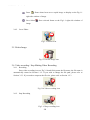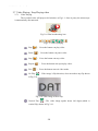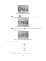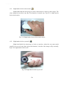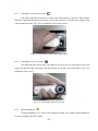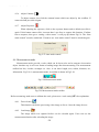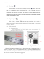
1
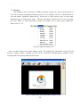
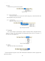
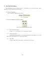
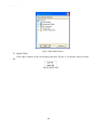
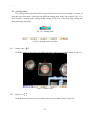
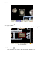
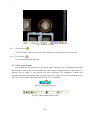
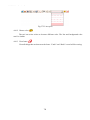
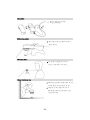
DediProg EzScope100 User Manual 2011/07 Update Ver.1.0 DediProg Technology Co. LTD 4F., No.7, Ln. 143, Xinming Rd., Neihu Dist., Taipei City 114, Taiwan Email for technical support: [email protected] Email for Sale information: [email protected] www.dediprog.com EzScope100 Software Installization Guide Contents 1. Please insert CD in CD player .................................................................................................... 7 2. Install UM-CAM application program ...................................................................................... 8 2.1 Start setup program ............................................................................................................ 8 2.2 Welcome to the UM-CAM Setup Wizard .......................................................................... 8 2.3 Choose installation route.................................................................................................... 9 2.4 Now installing program ..................................................................................................... 9 2.5 Complete install ............................................................................................................... 10 After installation complete ............................................................................................... 10 Install UM-CAM USB digital video driver ............................................................................. 11 3.1 Start to install driver program .......................................................................................... 11 2.6 3. 3.2 3.3 3.4 3.5 Welcome to use USB video device setup wizard ............................................................. 12 Now installing .................................................................................................................. 12 Install complete ................................................................................................................ 13 After installation complete ............................................................................................... 13 4. Uninstall UM-CAM AP ............................................................................................................. 14 4.1 Choose UM-CAM AP' s Uninstall driver as Fig.4-1 ........................................................ 14 4.2 Confirm to Uninstall UM-CAM ...................................................................................... 14 4.3 Uninstalling UM-CAM AP .............................................................................................. 14 4.4 Finish Uninstall ................................................................................................................ 15 5. Uninstall UM-CAM Driver ....................................................................................................... 16 5.1 Choose UM-CAM USB digital video driver to uninstall. See Fig.5-1 ............................ 16 5.2 Preparing to Uninstall. See Fig.5-2 .................................................................................. 16 5.3 Confirm to remove the UM-CAM Driver........................................................................ 16 5.4 In process of uninstall ...................................................................................................... 17 5.5 Finish Uninstall UM-CAM driver ................................................................................... 17 EzScope100 Software Manual Contents 1. Main Toolbars................................................................................................................................19 1.1 File ..................................................................................................................................19 1.1.1 Open File .................................................................................................................19 1.1.2 Save File..................................................................................................................20 1.1.3 Printer Setup............................................................................................................20 1.1.4 Print Picture ............................................................................................................21 1.1.5 Exit ..........................................................................................................................21 1.2 Setting .............................................................................................................................21 1.2.1 Input Devices Setting ............................................................................................ 22 1.2.2 Video Format ........................................................................................................ 22 1.2.3 Video Format Source ............................................................................................ 23 1.2.4 1.2.5 1.2.6 Video Compressor ................................................................................................. 26 JPG Quality ........................................................................................................... 26 Auto-Save ............................................................................................................. 26 1.3 Window ......................................................................................................................... 27 1.4 Tool ............................................................................................................................... 29 1.4.1 Restore default path .............................................................................................. 29 1.4.2 1.5 1.6 2. Open Data file ....................................................................................................... 29 Language ....................................................................................................................... 29 About............................................................................................................................. 29 Main Function Buttons ............................................................................................................... 31 2.1 Connect/Disconnect ...................................................................................................... 31 2.1.1 Connect ................................................................................................................. 31 2.1.2 Disconnect............................................................................................................. 31 2.2 Snapshot ........................................................................................................................ 31 2.3 Save Image .................................................................................................................... 32 2.4 Edit the Picture / Diverge From Editor's Picture .......................................................... 32 2.4.1 Edit picture ............................................................................................................ 32 2.4.2 Leave Editor .......................................................................................................... 36 2.5 Delete Image ................................................................................................................. 36 2.6 Video recording / Stop Making Video Recording ......................................................... 36 2.6.1 Recording .............................................................................................................. 36 2.6.2 Stop Recording...................................................................................................... 36 2.7 Video Playing / Stop Playing video .............................................................................. 37 2.7.1 Video Playing ........................................................................................................ 37 2.7.2 Stop broadcast ....................................................................................................... 38 2.8 Edit Image / Leave Editing ........................................................................................... 39 2.8.1 Image Editor.......................................................................................................... 39 2.8.2 Leave Image Editor ............................................................................................... 40 2.9 Print Image .................................................................................................................... 40 2.10 Diverge from the application program .......................................................................... 40 3. The File List/Folders ................................................................................................................... 41 3.1 The File Tabulates ......................................................................................................... 41 3.2 The File Tabulates On Page Number ............................................................................ 41 3.2.1 Show the number of pages .................................................................................... 41 3.2.2 3.2.3 3.3 4. Change page button............................................................................................... 41 Image Path ............................................................................................................ 41 Quick Click ................................................................................................................... 42 Four Mode Functions ................................................................................................................. 42 4.1 Comparison mode ......................................................................................................... 42 4.1.1 4.1.2 4.1.3 4.1.4 4.1.5 4.1.6 Load right side image............................................................................................ 43 Load image............................................................................................................ 45 Overlap comparison .............................................................................................. 45 Left side comparison ............................................................................................. 46 Right side comparison........................................................................................... 46 Top side comparison ............................................................................................. 47 4.1.7 Bottom side comparison ....................................................................................... 47 4.1.8 Window ratio adjustment ...................................................................................... 48 4.1.9 Transparent adjustment ......................................................................................... 48 4.1.10 Knockout color...................................................................................................... 48 4.1.11 Combined image ................................................................................................... 48 4.2 Aiming mode ................................................................................................................ 49 4.2.1 Draws cross ........................................................................................................... 49 4.2.2 Draw area .............................................................................................................. 49 4.2.3 Draw rectangle ...................................................................................................... 50 4.2.4 Draw Circular........................................................................................................ 50 4.2.5 4.2.6 Choose color ......................................................................................................... 51 Clear frame............................................................................................................ 51 Video control mode ....................................................................................................... 51 4.3.1 4.3.2 4.3.3 Right hand to look at observation ....................................................................... 52 Right hand to look at yourself ............................................................................... 52 Left hand to look at observation ........................................................................... 53 4.3 4.3.4 Left hand to look at yourself ................................................................................. 53 4.3.5 4.3.6 4.3.7 Adjust Brightness .................................................................................................. 53 Adjust Contrast ..................................................................................................... 54 Adjust Exposure .................................................................................................... 54 4.4 Measurement mode ....................................................................................................... 54 4.4.1 Freeze frame.......................................................................................................... 54 4.4.2 Load image............................................................................................................ 54 4.4.3 Save image ............................................................................................................ 55 4.4.4 Copy to clipboard .................................................................................................. 55 4.4.5 Scale setting .......................................................................................................... 55 4.4.6 Scale information setting ...................................................................................... 70 4.4.7 4.4.8 4.4.9 4.4.10 4.4.11 4.4.12 4.4.13 Measurement tool styles ....................................................................................... 70 Draw overlap line .................................................................................................. 75 Undo...................................................................................................................... 75 Redo ...................................................................................................................... 75 Line styles ............................................................................................................. 75 Choose color ......................................................................................................... 76 Clear frame............................................................................................................ 76 EzScope100 Tripod User Guide Tripod user manual ....................................................................................................... 80 DediProg EzScope100 User Manual EzScope100 Software Installization Gudide UM-CAM Installing EzScope100 installation. Please see the following steps to complete the UM-CAM To Step 1:1. Please insert CD. Step 2:2. Install UM-CAM application program. Step 3:3. Install UM-CAM driver. uninstall UM-CAM EzScope100 AP and driver in your PC, please follow below 2 steps to complete the Uninstall. Step 1: 4. Uninstall UM-CAM AP. Step 2: 5. Uninstall UM-CAM USB digital video driver. 1. Please insert CD in CD player Please insert the product CD to the CD-Rom slot. The computer will read the CD automatically and will pop up a window shown below: Fig.1-1 Setup window If the shown setup window can not pop up, please go to CD-ROM to select Autorun.exe execute file, which the same will pop up as Fig.1-1 setup window. Autorun.exe is shown below: Fig.1-2 Execute icon 73 UM-CAM Installing 2. Install UM-CAM application program Please select the image 1-1 and setup application program button to install UM-CAM program. 2.1 Start setup program Click setup application program, after it will pop up (please select a language) window on Fig.2-1, the initial language will follow up the pc OS system. If you want to cancel setup please click “Cancel” then click “OK”. Fig.2-1 Setup language window 2.2 Welcome to the UM-CAM Setup Wizard After choosing the language, go to welcome to the UM-CAM setup wizard window see Fig.2-2, then please click “Next” then continue. If want to cancel please click “Cancel” button. Fig. 2-2 Welcome to the UM-CAM setup wizard 84 UM-CAM Installing 2.3 Choose installation route Next step please choose the installation route window see Fig.2-3. If want to change file route click “Browse” to change setup path, then please click “install” then start installing. Fig. 2-3 Choose installation route 2.4 Now installing program Continue install wizard will start installing program as directory Fig.2-3. Fig.2-4 Now installing 95 UM-CAM Installing 2.5 Complete install When the UM-CAM program complete installation Fig.2-5. Please click “Finish”. Fig.2-5 UM-CAM wizard install complete 2.6 After installation complete Desktop will show UM-CAM short cut as Fig.2-6. Fig.2-6 UM-CAM shortcut Fig.2-7 UM-CAM at position all programs 10 6 UM-CAM Installing 3. Install UM-CAM USB digital video diver The driver is optional one, if you install it, you can have more additional functions added to the UM-CAM AP. Attention: Before install diver, please connect UM-CAM USB Microscope Camera to the computer. If not, you can’t install the program. 3.1 Start to install driver program Please select Fig.1-1 to start Installing UM-CAM drive. Firstly please make sure to connect UM-CAM to a pc. Otherwise, it will pop up Fig.3-1. Fig.3-1 Not found UM-CAM step up After click setup UM-CAM driver button, it will pop up Fig.3-2, now be ready to install the window. If cancel installation, please click “cancel” button. Fig.3-2 Getting ready to install 11 7 UM-CAM Installing 3.2 Welcome to use USB video device setup wizard Ready to install, please follow up the steps. Fig.3-3 Welcome to use USB video device Install wizard. 3.3 Now installing If you want to stop installation, please click “Cancel”. Fig.3-4 Now installing USB video device 12 8 UM-CAM Installing 3.4 Install complete Complete USB Video Device setup Fig.3-5, click “finish” and then driver program is completed. Fig.3-5 USB Video Device installation complete 3.5 After installation complete After installation is completed, the window on the right corner will show a video icon Fig.3-6. Start -> all programs will also have USB Video Device file shown Fig.3-7. Fig.3-6 USB Video Device icon UM-CAM can be executed from ICON AMCap as below Fig.3-6. However, AMCap is a simple tool for preview only and can’t support image process as the UM-CAM AP. Fig.3-7 USB Video Device is at all programs position. 13 9 UM-CAM Installing 4. Uninstall UM-CAM AP 4.1 Choose UM-CAM AP’s Uninstall driver as Fig.4-1 Fig.4-1 UM-CAM AP Uninstall 4.2 Confirm to Uninstall UM-CAM Please make sure if you want to completely remove UM-CAM application program. See Fig.4-2. Fig.4-2 4.3 Uninstalling UM-CAM AP In processing of uninstall the UM-CAM AP, see Fig.4-3 Fig.4-3 In process 14 10 UM-CAM Installing 4.4 Finish Uninstall UM-CAM AP was successfully removed from your PC, please click OK to finish. Fig. 4-4 Uninstall Completed 15 11 UM-CAM Installing 5. Uninstall UM-CAM Driver 5.1 Choose UM-CAM USB digital video driver to uninstall. See Fig.5-1 Fig. 5-1 Uninstall UM-CAM USB digital video driver 5.2 Preparing to Uninstall. See Fig.5-2 Fig. 5-2 Preparation 5.3 Confirm to remove the UM-CAM Driver Please make sure if you want to completely remove the Driver. See Fig. 5-3 Fig. 5-3 Confirmation of uninstall 16 12 UM-CAM Installing 5.4 In process of uninstall In processing of uninstall the UM-Cam Driver, see Fig.5-4 Fig.5-4 Uninstalling Driver 5.5 Finish Uninstall UM-CAM driver Fig.5-5 Finish uninstall 17 13 DediProg EzScope100 User Manual EzScope100 Software Manual UM-CAM Application Program After the user use UM-CAM application program, it will show illustration picture in Fig.1-1.A tool is arranged and divided into the window. The main button and file tabulate is in 3 groups, which the left and right windows are the two sub windows. On the left window, it will show UM-CAM whether USB digital video device is connected. If it’s not connected the button will be a white result as Fig.1-2 shows. If the PC OS is Windows 2000 and can not open the PRO10 AP(wmvcore.dll cannot be found), please update your Windows Media Player to Version 9.0 or above. Fig.1-1 Main window picture Fig.1-2 Connected button white In the following, those main functions will be divided into four groups, which includes: 1. Main Toolbars See Fig.1-3 the toolbars of the application program which commonly uses, includes File, Setting, Window, Tool, Language and About altogether. Fig.1-3 Main Toolbars 19 5 UM-CAM Application Program 2. Main Function Buttons Fig.1-4 is a main function buttons which are commonly used or is for basic function, which includes connecting, taking photos, saving photos, editing…etc. there are 10 functions button. Fig.1-4 Main button group 3. The File List/Folder Fig.1-5 is the tabulate of the saved images in the application program. The main list will list the files in the existing folder, which includes BMP folder, JPG folder and AVI folder. Fig.1-5 File List 4. Four Mode Functions After open UM-CAM program, please click connect button shown in Fig.1-1, when it is connecting, four mode functions toolbar will show under the left side of sub-window. Fig.1-6 AP connecting 20 6 UM-CAM Application Program 1. Main Toolbars The tool arranges the group and pursues to show, which include file, setup, window, tool, Language and select greatly about 5 of the choices altogether. 1.1 File In the beginning, “File” is used for users who want to open/save file from other path or Print setting...etc see Fig.2-1. Fig.2-1 Choose file 1.1.1 Open File Here are three types of file formats in the Open File, Bmp, Jpg and Avi as optional. The default route for the open file folder is according to the current preserving file format. About tabulates of the file folders, please refer to Section 3.1 for more detailed information. In short, please refer to below Fig.2-2, if the preserving photo is in Bmp tabulate, the open file route is for preserving Bmp photos. If the preserving photo is in Jpg tabulate, the open file route is for preserving Jpg photos. If the preserving video is in Avi tabulate, the open file route is for preserving Avi videos. Ctrl +O are a fast key. Fig.2-2 Opening bmp file 21 7 UM-CAM Application Program 1.1.2 Save File There are only two file types for saving, Bmp and Jpg; the saved file is the image taken in the left sub-window,see Fig.1-1. The storing file name is named by the program automatically; the user can change the name by themselves. File name is annual in year (yyyy), month(mm),day(dd),hour(hh),minute(nn),second(ss)setting,which.Bmp_20080829180445.bm p as 2008(yyyy) 08(mm) 29(dd) 18(hh) 04(nn) 45(ss), which this way is the name of file won’t be repeated and can also be realized the date and time by stored file name. Fig.2-3 Save file 1.1.3 Printer Setup Set up printer can adjust paper between size, source or printer type. Fig.2-4 Setup printer 22 8 UM-CAM Application Program 1.1.4 Print Picture Ctrl+P are a fast key Fig.2-5 Print 1.1.5 Exit Once to choose to exit, the program would close. Ctrl+E are a fast key. 1.2 Setting The Setting function is mainly to set up Video Format and JPG compression quality as Fig.2-6 shows. If UM-CAM device isn’t at the line, video format and video signal source unable to set up (setting in white bar); it can set up on the contrary. Fig.2-6 Select Setting 23 9 UM-CAM Application Program 1.2.1 Input Devices Setting Optional Input Devices, see Fig.2-7, when there are 2 or more Input Devices connecting to PC at the same time, you can choose which device you wish to use. Fig.2-7 Optional Input Devices 1.2.2 Video Format Video Format is mainly to set up the frame rate, color space and output size etc. Frame rate is frame numbers per second (fps) for playing. Adjust the output size will slower or faster the fps, for example, if the fps is higher, the preview video will be less clearly but with smooth performance. On the contrary, if the fps is lower, the image will be more clear but with a little lagging performance. This is due to the more frames requires the more CPU loading then cause the lagging performance. The Color space are RGB24, YUY2 and I420. Fig.2-8 Video format table before installing UM-CAM driver Output the image size means the video quality, the default output size is 640*480; the user may change to preference output size such as 320*240, 800*600, 1280*960…etc. The size changed higher, the resolution will be higher, and the data quantity per second is bigger. The snapshot image size is according to output image size. Fig.2-8 is Windows built-in driver, which Color 24 10 UM-CAM Application Program Space/Compression allows to choose YUY2 only, the output size is limited, too. Fig.2-9 is table of Video Format in installing UM-CAM driver, the Color Space includes YUY2, RGB24 & I420, and more Output sizes are optional. Fig.2-9 Table of Video Format of UM-CAM driver 1.2.3 Video Format Source Fig.2-10 & Fig.2-11 are Properties of Video Format source without installing UM-CAM driver, i.e., it uses Windows’ built-in driver. Fig.2-10 Video Proc Amp allows User to adjust the parameter. Fig.2-10 Table of Video Proc Amp content without installing UM-CAM driver Fig.2-11 Table of Camera Control allows User to adjust the parameter. In generally, Windows built-in driver can support limited functions. 25 11 UM-CAM Application Program Fig. 2-11 Table of Camera Control without installing UM-CAM driver Fig.2-12, 2-13 & 2-14 are properties of Video Format source with installing UM-CAM driver. Firstly, it sets up Video image quality for Brightness, Contrast, and Gamma etc. as Fig.2-12. If the Video image is rotating, it can use vertical rotating and horizontal rotating. Besides, other functions can be applied by User. Fig.2-12 Properties of Video Format source with installing UM-CAM driver Fig.2-13 is Function of special Video Effects, beside of effects, there is Frame function, the Frame styles can be customer zed. 26 12 UM-CAM Application Program Fig.2-13 Properties of Video Format source with installing UM-CAM driver Fig.2-14 It can enlarge and shrink the image, also move the position and enable face tracking. Fig.2-14 Properties of video format source with installing UM-CAM driver 26 13 UM-CAM Application Program 1.2.4 Video Compressor Normally, the video size is huge before compressor. We can use Compressor function to reduce the file size. There are optional Compressors which are built-in or can be installed by DIVX or other tool. Once the installation is completed, you can see them at the optional Compressors. Fig.2-15 Optional Compressors 1.2.5 JPG Quality User can choose different JPG quality. The JPG compressor could distorted the saved image in order to meet the saving size, in this situation, when the saved quality is low, the image quality could be low and the file size is low too. See Fig.2-16 Fig.2-16 Setting JPG qualities 1.2.6 Auto-Save From “Setting->Auto- Save” shown Fig.2-17, after checked auto-save, when clicking the save buttons it will not show the save dialog. The system will generate a file name and auto-save the file. Fig.2-17 Auto-save option 28 14 UM-CAM Application Program 1.3 Window The Windows can be chosen per USER’s preferred window size. But it need depend on User’s PC to choose a suitable resolution as Fig.2-18. For example, your PC is 1280*960 pixels; you can choose 1280*960. When the PC screen size is wide screen (16:9), it may cause imbalance ratio at “Full Screen” mode. The user may choose “Full Screen (4:3)” for an equally true ratio. When in “Video Resolution” mode, the window size is same as the output size. Please refer to 1.2.2. Fig.2-18 Optional window size User can choose full screen under window mode. The original left sub-window in the AP will become a single window, available tool bar of the connection (disconnection), snapshot, video recording and video playing under the full screen. Fig.2-19 Full screen of 640*480 under Window mode 29 15 UM-CAM Application Program If changing to single window and want to return to normal mode, please click “Normal Mode button” see Fig.2-10 Fig.2-20 Normal Mode Single window also has 4 functions of video control mode shown Fig.2-21. To preview other functions of “video control mode” please refer to section 4.3. Fig.2-21 4 Functions of Video Control Click snapshot button and will pop up Fig.2-22, it provides function of Open file, Save file, Delete image, Image process and Print image. Fig.2-22 Image View of window 30 16 UM-CAM Application Program 1.4 Tool Use the Tool to open file and set up Path. Fig.2-23 Tool 1.4.1 Restore default path The function allows User to preserve the initial setting route, easily find and Save the video and photos at the preserved route. 1.4.2 Open Data file Open files at BMP, JPG & AVI folder. Fig.2-24 Open file folder 1.5 Language The version includes 5 multi-languages; English, Traditional Chinese, Simplified Chinese, Japanese & German. The initial language will automatically follow up User’s OS system. It can choose the other language, too. Fig.2-25 Select language 1.6 About Show the UM-CAM relevant information. Fig. 2-26 Select about Learn the application program version, UM-CAM hardware manufacturer and the copyright of the application program. 31 17 UM-CAM Application Program Fig.2-27 About UM-CAM 32 18 UM-CAM Application Program 2. Main Function Buttons Main function button group see Fig.1-4 which are commonly used or basic function, which includes connecting, taking pictures, saving, editing…etc. there are 10 functions button. Fig.1-4 Main button group 2.1 Connect/Disconnect 2.1.1 Connect The connect icon is as Fig.3-1, the user will connect the line while pushing the connect button, namely connect with UM-CAM device. If it cannot connect, please reinsert UM-CAM device to the other USB port. Fig.3-1 Connect button icon 2.1.2 Disconnect The button icon which shows disconnect is like Fig.3-2, by clicking this button to disconnect.When the user starts to play the video, UM-CAM will be disconnected automatically. When re-connecting the UM-CAM with the AP, the video format will go back to the default value. Fig.3-2 Disconnect button icon 2.2 Snapshot Snapshot icon is as Fig.3-1, the function allows taking a photo in Preview, Video & Play, and image size depends on Video Format source, i.e. Height & Width. Fig.3-3 Snapshot button icon 33 19 UM-CAM Application Program 2.3 Save Image Save image icon is as Fig.3-4, the saved file name is automatically created. The detail of the file name is as description 1.1.2. Fig.3-4 Save image button icon 2.4 Edit the Picture / Diverge From Editor's Picture 2.4.1 Edit picture The editor is as Fig.3-5 including several convenient functions. When clicking editor icon as Fig.3-5, the toolbar for editing image will show up as Fig.3-6 Fig. 3-5 Editor icon Fig.3-6 Editor tool The editing toolbars are upper roll and button roll. Please click the original fit( pen( ), line( ), rectangle( ) first then start to use the button roll tools. ), ellipse( The edit text, ) fucntions are only available until the original fit has been selected. Fig.3-7 Click ( When click the edit text ( edit background color ( ) to start editor tool ) butoon, see Fig.3-8, the edit text group includes Edit text color( ), edit background color transparent ( 34 20 ). ), UM-CAM Application Program Fig.3-8 Click ( When click select ( ) to start text tool ) butoon and use mouse to draw the range, the select group tools are available as Fig.3-9. The select tools includes cut ( Fig.3-9 Click ( ), copy ( ), paste ( ), save select ( ). ) to start other functions “Editor Image” toolbar includes many functions, below will explain each function: Normal :When this button is clicked, all the buttons will return to normal. Move Image :When the “original fit ” button begins using, select “Move Image” and click mouse of left button to move on the image. New File :“New file” can open a blank page of image, image size is 400*300 by the Fig. 1-1 of the right side window size. Save Image :Save Fig.1-1 is right side window of image.The image size by video formal of output size. Rotate Left :Image can rotate left 90 degree. Rotate Right :Image can rotate right 90 degree. Fit The Window :This function can let image to fit the window size. When selecting this function, it cannot use “edit text”, “select”, and “drawing” functions. Zoom In :Enlarg image without interpolation therefore if the scale larger than orginal size distortion will appare. 35 21 UM-CAM Application Program Zoom Out :To shirk image. Rndo :To go back the movemenet and only can use up to 3 times. Redo :To go to next movemenet and only can use up to 3 times. Line Style :Choose line style by clicking “Line style” button and it will pop up Fig. 3-10 dialog box. Fig.3-10 Choose line styles Color :To choose pen’s “color” click on the color button and it will pop up Fig. 3-11 dialog box. Fig.3-11 Choose color 36 22 UM-CAM Application Program Delete Image Exit Editor :The Fig.1-1 right side window of image will be deleted. :To exit image editor,the “image editor” toolbar will be closed. Orignal Fit :When the image size is bigger than the window, using this function, it can do “Edit text”, “select”, and “drawing” functions. The window won’t see the whole image, but only some parts. Edit Text :Edit text is words that can be written on image. Edit Text Color :Text color can be changed by clicking “edit text color” button and it will pop up Fig.3-11 dialog box. Edit Text Background Color :Text background color can be changed just by clicking “edit background color” and it will pop up Fig.3-11 dialog box. Edit Text Background Transparent :Text background can be set as transparent with no background color. Text Size Pen :Text size can be changed. :Pen can draw anything and its function is like a regular pen and pencil. Line :Draw stright line. Rectangle Ellipse Select :Draw rectangle. :Draw ellipse. :Selects the area on the image, after the selection, it can cut, copy, paste, and save the selection area function. Cut Copy :Cut frame on the Fig.1-1 right side window of image. :Copy selected frame on the Fig.1-1 right side window of image. 37 23 UM-CAM Application Program Paste :Paste whats been cut or copied image to display on the Fig.1-1 right side window of image. Save Select :Save selected frame on the Fig.1-1 right side window of image. 2.4.2 Leave Editor Fig.3-12 Editor icon 2.5 Delete Image Fig.3-13 Delete image icon 2.6 Video recording / Stop Making Video Recording 2.6.1 Recording Press video recording icon see Fig.3-14 and firslty name the file name, the file name is automatically created as Section 1.1.2. If you wish to change the file path, please refer to Section 3.2.3. If you need to compress the file size, please refer to Section 1.2.3 Fig.3-14 Video recording icon 2.6.2 Stop Recording Fig.3-15 Stop recording icon 38 24 UM-CAM Application Program 2.7 Video Playing / Stop Playing video 2.7.1 Video Playing The recorded video will plays at left window as Fig.1-1. Once it palys, the microscope is automatically disconnected. Fig.3-16 Film broadcasting icon Fig.3-17 Tool of playing Play “ Pause “ Stop “ Repeat “ Exit “ ”: Press the button can play video. ”: Press the button can pause video. ”: Press the button can stop video. ”: Press the button can repeat play video. ”: Press the button can exit video mode. No Flip “ ”:Video image’s flip direction, does not makes any flip shown in Fig.3-18. Fig.3-18 Video image with no flip Vertical Flip “ ”:The video image upside down 180 degree,which is vertical flip, shown in Fig.3-19. 39 25 UM-CAM Application Program Fig.3-19 Video image do vertical flip Horizontal Flip “ ”:The video image left and right mirror 180 degree flip which is horizontal flip shown in Fig.3-20. Fig.3-20 Video image do horizontal flip Vertical and horizontal Flip “ ”:The video image will do horizontal and vertical flip shown in Fig.3-21. Fig.3-21 Video image becomes horizontal flip Click right of mouse to show Fig.3-22 Fig.3-22 2.7.2 Stop broadcast Once it stops play, the microscope is still disconnected. 40 26 UM-CAM Application Program Fig.3-23 Stops broadcasting 2.8 Edit Image / Leave Editing 2.8.1 Image Editor Image processing editor as Fig.3-24, UM-CAM AP provides users few simple image processing editing functions. Fig.3-24 Image Editor Icon While clicking the Image editor icon, the image processing editing function buttons as Fig.3-25 will show up on the right sub-window Fig.1-1. Fig.3-25 Image Processing Editing Fig.3-25 Tool of Image Editor Once it clicks , it can set up the value. The image will be changed, too. Fig.3-26 Changing Threshold Original Image “ Gray Level “ ”:This button can let image return to original image. ”:This button can let the image from color change to gray. Highlight Edge “ ”:This button can let the image show it’s highlight edge. Highlight Pxiel “ ”:This button will strengthen in the picture between the different pixels. Black/White “ ”:This button can let the image from color turn to black and white. 41 27 UM-CAM Application Program Inverse “ Exit “ 2.8.2 ”:This button can let the image become inverse. ”:This button is to exit video mode. Leave Image Editor Fig.3-27 Leave Image Editor 2.9 Print Image Fig.3-28 Printing image 2.10 Diverge from the application program Fig.3-29 Diverges from the application program 42 28 UM-CAM Application Program 3. The File List/Folders The file tabulates pages and signs as Fig.1-5, file tabulates is to list all file folders, which includes JPG folder, Bmp folder, and Avi Folder. 3.1 The File Tabulates Fig.4-1 tabulate for BMP, JPG & AVI files Fig.4-1 Fle tabulates 3.2 The File Tabulates On Page Number Fig.4-2 The file tabulates on page number 3.2.1 Show the number of pages 001/001= X/ Y, X is sequence and Y is total number of pages. 3.2.2 Change page button Fig.4-2 left and right button can be change page number. Left button is to decrease page number and right button is to increase page number. 3.2.3 Image Path Click the “Image Path” to show Fig.4-3 and choose the file director 43 29 UM-CAM Application Program Fig.4-3 Data Path Director 3.3 Quick Click Click right of Mouse on the saved image and show Fig.4-4, it can directly Open or Delete file. Fig.4-4 Quick click 44 30 UM-CAM Application Program 4. Four Mode Functions When connecting the AP with UM-CAM, the four mode functions will show up on the button position under left sub-window. The four mode functions are comparison, aiming, video control, and measurement, see Fig.5-1. Select different mode to show the toolbar for operating. 1. Comparison mode : Comparison mode can do overlapping two frame. The frame can be whole or any size to compare. This mode can see two frams of simiarities. 2. Aiming mode : Provides a cross, area, rectangle and circular different aiming mode to aim the observation object .That can help capture observation object. : 3. video control mode The mode can control left hand or right hand to hold the machine, which can capture yourself or opsiticles, but the directions might not be correct. It can use the mode to adjust the dirctions and it can adjust contrast, brightness and exposure. 4. measurement mode : Measurement mode has ruler functions to measure at real time, which provides different measurement tools. Fig.5-1 Mode of toolbar 4.1 Comparison mode When connected, the defult of the toolbar is set as to compare shown in Fig.5-2 and Fig.5-3. In Fig.1-6 right sub-window has no image so some part of the buttons wouldn’t work in this mode. Comparesion mode can be overlap with another video image to compare and to cut half of the image for comparession. Fig.5-2 Comparison mode Fig.5-3 Comparison mode toolbar 45 31 UM-CAM Application Program 4.1.1 Load right side image “ ” When capture one imge or open one image, the Comparison toolbar of “load right side image“ ” button can be choosen. Shown in Fig.5-4. Fig.5-4 Right side widow has image When clicking “load right side image“ ” button see Fig. 5-4, image comparing functions is available see Fig.5-5. It can overlap image or cut half of the image and load into left sub-window for comparing. If want to leave comparison mode please click “load right side image“ back preview mode. Fig.5-5 Loading image will be compared 46 32 ” again to go UM-CAM Application Program 4.1.2 Load image “ ” When the right sub-window doesn’t have image Fig.5-6, load & select image from file folder by clicking “load image“ ” button. Fig.5-6 Load image button Click “Load image” button. After opening the file, it can use overlapping and cut half image function. See Fig.5-7. If want to exit the program just click on “Load image” to go back to preview mode. Fig.5-7 After loading image 4.1.3 Overlap comparison “ ” The “overlap comparison” can makes the image transparence. With overlap in the video image, then at the same time shows two frames. Show in Fig.5-8. 47 33 UM-CAM Application Program Fig.5-8 Overlap comparison 4.1.4 Left side comparison “ ” When the window separates into left and right sides, the left side frame is video image, and the right side frame is loaded image. Show in Fig.5-9. Fig. 5-9 Left side comparison 4.1.5 Right side comparison “ ” The window separates to left and right, the right side frame is the video image and left side frame is loaded image. Show in Fig.5-10. 48 34 UM-CAM Application Program Fig.5-10 Right side comparison 4.1.6 Top side comparison “ ” Window separates into two half which is top and bottom. Top is video image, and bottom is loaded image. Show in Fig.5-11. Fig.5-11 Top side comparison 4.1.7 Bottom side comparison “ ” Window separates into two half, bottom side is video image, and top side is loaded image. Show Fig.5-12. 49 35 UM-CAM Application Program Fig.5-12 Bottom side comparison 4.1.8 Window ratio adjustment When choose half compare, can use this function to adjust the frame of ratio. Show Fig.5-13. Fig.5-13 Window ratio adjust by scrollbar 4.1.9 Transparent adjustment Image can be adjusted from the scrollbar to change the pictures transparency. Show Fig.5-14. Fig.5-14 Transparency adjust by scrollbar 4.1.10 Knockout color “ ” Choose to knockout background color and some color on image can be cut out. 4.1.11 Combined image “ ” Before capture image click the button, which will combine video image and loaded image to combine. If not, the capture images will only video image. 50 36 UM-CAM Application Program 4.2 Aiming mode The aiming mode may draw different type like the cross, circular, rectangle, and area. It helps the user observation. It can draw the different aiming mode in the video image. Fig.5-15 is the selection to aiming mode, aiming toolbar shown in Fig.5-16. This mode may overlap the different aiming functions. Fig.5-15 Aiming mode Fig.5-16 Aiming mode of toolbar 4.2.1 Draws cross “ ” Click this button to draw the cross which may adjust the size by scrollbar. Show in Fig.5-17. Fig.5-17 Draws cross 4.2.2 Draw area “ ” Click the button to draw the area to adjust the size by scrollbar. Show in Fig.5-18. 51 37 UM-CAM Application Program Fig.5-18 Draw area 4.2.3 Draw rectangle “ ” Click this button to draw the rectangle to adjust the size by the scrollbar. Show in Fig.5-19. Fig. 5-19 Draw rectangle 4.2.4 Draw Circular “ ” Click this button to draw circular to adjust size by scrollbar. Show in Fig.5-20. 52 38 UM-CAM Application Program Fig.5-20 Draw Circular 4.2.5 Choose color “ ” Click this button, will pop up choose color dialog box and from there to choose color. 4.2.6 Clear frame “ ” To clear all aiming lines on fame 4.3 Video control mode This toolbar has the functions to flip video image. When the left or right hand holds the microscope to look at self or observation, the video image will flip and move direction to be opposite. By the mode, it can preview the correct direction. The brightness, contrast and exposure tool can be adjusted and also can cause the video image to be clearer in different scene. Fig.5-21 is the selection video control mode. Fig.5-22 is its toolbar. Fig.5-21 Video control mode Fig.5-22 Video control mode toolbar 53 39 UM-CAM Application Program 4.3.1 Right hand to look at observation “ ” Right hand holds the microscope to look at observation or observes other people. The video image does not have any flip. This function is normal way. Fig.5-23 is right hand to look at observation. Fig. 5-23 Right hand to look at observation object 4.3.2 Right hand to look at yourself “ ” Right hand holds the microscope to look at ourselves, when the user must watch oneself or use as web-cam, then selects this function, it lets the video image to flip vertically. Fig.5-24 is right hand to look at self. Fig.5-24 Right hand to look at your self 54 40 UM-CAM Application Program 4.3.3 Left hand to look at observation “ ” Left hand holds the microscope to look at the observation or observes other people. When the right hand holds the microscope, selects this function, it lets the video image to flip vertical and horizontal. Fig.5-25 is left hand to look at observation. Fig.5-25 Left hand to look at observing object 4.3.4 Left hand to look at yourself “ ” Left hand holds the microscope and whiling to look at self as a web camera, the video image will flip left-right 180 degree. By this function it can flip correct directions. Fig.5-26 is left hand to look at self. Fig.5-26 Left hand to look at your self 4.3.5 Adjust Brightness “ ” To adjust brightness is to click on the brightness button. By scrollbar adjust brightness. If want to default just click it again. 55 41 UM-CAM Application Program 4.3.6 Adjust Contrast “ ” To adjust contract just click the contrast button which can adjust by the scrollbar. If want to default just click it again. 4.3.7 Adjust Exposure “ ” When adjusting the exposure, click on the exposure button and to default just click it again. If this button cannot click, it means there’s no diver to support this function. If adjust has no response, then go to “setting->video source” it will pop up shown Fig.5-6. The “auto mode control” must be unchecked. If want to use “auto mode control” must be checked again. Fig.5-27 Auto mode control 4.4 Measurement mode Measurement mode provide a scale which can be draw ruler and to measure observation object. Another way is to Freeze frame or loading image after then measuring. The measurement toolbar has line, circular, rectangle etc. Also, it can show length, area, radius, diameter, etc, information. Fig.5-28. is measurement mode; its toolbar is shown in Fig.5-29. Fig.5-28 Measurement mode Fig.5-29 Measurement mode toolbar Before measuring, make sure to calibrate the scale, please note “scale setting 4.4.1 Freeze frame “ ” the explanation. ” This function can let the previewing video image to freeze. Once the image freezes. 4.4.2 Load image “ ” The image which was captured before can be reloaded again. Users can use the measurement function after reloading the image 56 42 UM-CAM Application Program 4.4.3 Save image “ ” After measuring, it can save image by clicking “save image “ ” button. The save file name will be marked as vertical and horizontal scale. If want to load the image to do measurement, then just click “scale setting” “ ” button to set vertical and horizontal scale, and these scale of value form file name. If file name has v420h560 of string means horizontal 5.60mm and is vertical is 4.20mm. 4.4.4 Copy to clipboard “ ” Select “Copy to Clipboard” “ ” button then the current frame will be copied to clipboard ,also, it will be pasted to right side windows at Fig.1. After copying, it can be pasted on word or excel. Etc. 4.4.5 Scale setting “ ” (1) Select suitable ruler Before setting scale, first find the higher accurate ruler to measure. Use generally ruler shown as Fig.5-30. Fig. 5-30 Metal ruler a b c d Fig. 5-31 Calibrator “Calibrator” is designed for calibration. Fig.5-31. There are three types of the ruler and 4 kinds of pictures, (a) Concentric Circles, (b) Low Magnification Grid, (c) Cross, and (d) High Magnification Grid. Please make sure to place the calibrator in correct position due to different side of front and back will cause measurement value incorrect or inaccuracy. 57 43 UM-CAM Application Program a. Concentric Circles: To measure a round hole. Place the Concentric Circles (See above chart a) directly onto PCB drilling hole, the diameter can be measured from the concentric circle scale. Diameter: 3.00mm. See Fig. 5-32. Fig.5-32 Concentric Circles b. 1mm Low Magnification Grid: To place the grid (See above chart b) on the object as the bill Fig.5-33, the length for each square is 1mm. Fig.5-33 Low Magnification Grid c. Cross: The main purpose for the Cross is to calibrate the program and also as a measurement. The Cross (See above chart c) has 3 kinds of units as 0.05mm, 0.1mm and 1mm scale. It will measure 0.05mm, 0.1mm at high magnification and 0.1mm, 1mm at low magnification. The Cross can measure the Length and Width accurately, ie.: Fig.5-34, Measure the length of the onion cell as the red rectangle which is approximate 0.400mm. 58 44 UM-CAM Application Program Fig.5-34 The Cross d. 0.1mm High Magnification Grid: See Fig.5-35, put the 0.1mm scale (See above chart d) on “ ” microdot. The Length of in a square i.e. 0.100mm. Fig.5-35 High Magnification Grid 4 kinds of applicable method is same. Because the calibrator is transparent, simply place it onto the object, then put the machine onto the calibrator for observing. The use “metal ruler” and “calibrator” the biggest difference is as follows: When the magnification is high, use the calibrator can easily and accurately knows the scale range. When the magnification is high, metal ruler is less accurately than a calibrator. When the magnification is low, a metal ruler can be suitable. (2) Calculate scale rang First, the scale setting must calculate the horizontal and vertical scale range, the following has several steps to decide the scale range, suggested that the windows size adjust 640*480 the single windows: To decide measure distance between machine and observation objects. 59 45 UM-CAM Application Program To adjust the focus to see the image as clear as it can. Calculate the observation video image of horizontal and vertical scale. Calculate the range shown in Fig.5-36. After setup the horizontal and vertical scales, the machine, the observation distance and focus are not allow to readjustment. Fig.5-36 Horizontal and vertical measurement range (3) Calibrate “contacted” and “non-contacted” scale Contacted scale: Put the machine onto the calibrator for small field of view , it can apply for a focus point at Low or High magnification. Non-contacted scale: To hold the machine by the supporter, fix the machine overhead a ruler for a certain distance, it can observe a wider field of view. Non-contacted scale is only for low magnification. See Fig.5-37. Contacted Non-Contacted Fig.5-37 Contacted and Non-Contacted 60 46 UM-CAM Application Program According to the above steps it can measure horizontal and vertical scale. Several examples as follows: EX1: Measurement for non-contact object. Use the “metal ruler” as a measurement base, the machine and the observation object of distance is 2.6 cm, the focus of the video image is clear. Image shown in Fig.5-38 and Fig.5-39 is the result after measurement, horizontal and vertical scale range is 24.2mm and 18.1mm. Fig.5-38 Horizontal scale range is 24.2mm Fig.5-39 Vertical scale range is 18.1mm 61 47 UM-CAM Application Program EX2: Measurement for contacted object in low mag. Use the “metal ruler” for measurement of the base, the machine and the observation object of distance is close, the focus of the video image is clear. Image shown in Fig.5-40 and Fig.5-41 is the result after measurement, horizontal and vertical scale range is 5.60mm and 4.20mm. Fig.5-40 Horizontal scale range is 5.60mm Fig.5-41 Vertical scale range is 4.20mm 62 48 UM-CAM Application Program EX3: Measurement for contacted object in high mag. Use the “metal ruler” for measurement of the base, the machine and the observation object of distance is close, the focus of the video image is clear. Image shown in Fig.5-42 and Fig.5-43 is the result after measurement, horizontal and vertical scale range is 1.40mm and 1.05mm. Fig.5-42 Horizontal scale range is 1.40mm Fig.5-43 Vertical scale range is 1.05mm 63 49 UM-CAM Application Program EX4: Calibrate the scale for contacted in low mag. Use the “calibrator” for measurement of the base, the machine and the observation object of distance is close, the focus of the video image is clear. Image shown in Fig.5-44 and Fig.5-45 is the result after measurement, horizontal and vertical scale range is 5.60mm and 4.20mm. Using “calibrator” can be easier and accurate to get scale range. Fig.5-44 Horizontal scale range is 5.60mm Fig.5-45 Vertical scale range is 4.20mm 64 50 UM-CAM Application Program EX5: Calibrate the scale for Contacted in high mag. Use the “calibrator” as a measurement base, flatly put the machine on the observing object, adjust the focus to find the clearest image. See Fig.5-46 and Fig.5-47 the result from measurement. Horizontal and vertical scale range is 1.40mm and 1.05mm. Using a calibrator is more easily and accurately to get scale range. Fig.5-46 Horizontal scale range is 1.40mm Fig.5-47 Vrtical scale range is 1.05mm 65 51 UM-CAM Application Program (1) Factors cause the inaccurate on the measurement There are few factors could cause the inaccurate on the measured figures. The used ruler is not exactly accurate, for example, a metal ruler is not accurate than a calibrator. Because of the discrepancy, it is unable to know the accurate horizontal and vertical scale range, too. The resolution is not the same with the Windows size. Why is the resolution not the same with the Windows size? For example the present resolution (original video image of output size) is 640*480 the measurement of the Windows's for general is 400*300 sizes. When the original video image size is 640*480 by reducing to 400*300, the measurements will have caused error. Therefore, the measurement is to adjust the resolution size and windows size to become the same. To chooses the application toolbar. “Setting”-> video format will pop up shown in Figure Fig.5-48, to change “output size” value then, this output size expression video source resolution. Fig.5-48 Resolution adjustment Another window adjusts as shown Fig.5-49 below. 66 52 UM-CAM Application Program Fig.5-49 Window size adjustment (2) Setting scale The setting scale dialog box show in Fig.5-50. The following several to explain operation Fig.5-50 Setting scale dialog Scale default file Scale default files have two types “Default Height Magnification” and “Default Height Magnification” shown in Fig.5-51 67 53 UM-CAM Application Program Fig.5-51Scale default File When the microscope is observing object with contacted distance, it has two focus points. Thus, it will have two kinds of scale value which are for low and high mag. When in low mag, the horizontal and vertical scale is 5.6 mm and 4.2mm. And when in high mag., the horizontal and vertical scale is 1.4mm and 1.05mm. If the default value is not right for the user, the scale value can reset or create a file for new value by calibrate the horizontal and vertical scale according to the user’s preferences. If want to return to the default file, check “Scale default” box than it will return back to two default files and the other files will be deleted. Create a new scale file Click “new” button than it will pop up shown in Fig.5-52 a dialog box and input new scale name. Fig.5-52 New scale name file dialog After creating new file, input vertical and horizontal’s scale value shown in Fig.5-53 and if want to change scale color, select on “choose color” button to change color. 68 54 UM-CAM Application Program Fig.5-53 Input vertical and horizontal scale value Scale ratio The machine’s Sensor of image ratio is 4:3, if checked fixed ratio, then the horizontal and vertical scale will make the adjustment by 4:3 ratio, shown in Fig.5-54. For example, input in the horizontal scale value to 410, the vertical scale value will automatically adjust to 307. On the other hand, due to the AP will automatically calculate the scale range for horizontal or vertical scale, thus, the user just need to measure and enter one of the horizontal or vertical scale. i.e., while only measure and enter the horizontal scale range, it can calculate the vertical scale range automatically. Fig.5-54 Fixed ratio adjustment Set ruler position & show (0,0) position Ruler can display at Horizontal or Vertical position as per example per below Fig.5-55 options. The image results in Fig.5-56. 69 55 UM-CAM Application Program Fig.5-55 Ruler vertical and horizontal position setting Fig.5-56 Ruler vertical and horizontal Display To delete and rename scale file Choose delete or rename the file from the drop down menu, see Fig.5-57 Fig.5-57 Drop down menu choose file Semi-Auto Calibration Set up a customized semi-auto Calibration. See Fig.5-58. “Input Measurement Length” means the real length. For example, enter 400 means 4.00mm, enter 50 means 0.5mm. The Display Scale check-box is to decide to show the Display 70 56 UM-CAM Application Program Scale or not. If click the Horizontal Fixed, only a horizontal axis can draw on the image; on the contrary, if click the Vertical fixed, only a vertical axis can draw on the image. If choose “None”, axis can draw from any direction. A horizontal or vertical axis can be draw by pressing ‘shift’ button on your keyboard together with clicking mouse left. After it is completed, please click “Finished” for saving the new scale. Fig.5-58 Input the actual measurement length The calibration frame can be freezed by pressing the right button on the mouse. The freezed frame helps for calibrating in a stable condition. (1) Put the calibrator under the machine and adjust focus to clearly see the scale. (2) Key in “400” length in the check-box of “Input Measurement Length”. (3) Use mouse to draw a yellow line for 4.00mm. (4) Click “Finished” to complete and save the new calibration figure. The new setting scale (Calibration Scale [New]) show on the frame. See Fig.5-59. Fig.5-59 Draw a line in actual length 71 57 UM-CAM Application Program 4.4.6 Scale information setting “ ” This setup screen indicates to set whether to show the unit value or not, see Fig.5-60. Choose “length” means to display the length of the line, by capital letter “L” expression, if length is 2.33mm, it will show L=2.33mm besides the line. If choose “none”, no value will show on the dialogue. If show “P” means “perimeter”, “A” means “Area”, “C” means “Circumference, and “R” means ”radius”. Fig.5-60 Scale information setting dialog The “precision” is refers to under the decimal point of effective number of digits. The effective number of digits can be adjusted. “Choose color” may choose the text color. “Display unit” does not check its unit “mm” did not display. Attention, after setting option, and also choose the “measuring means style”. 4.4.7 Measurement tool styles The measuring include optional Line, 2 Points Circle, 3 Points Circle, Ellipse, Square, Rectangle, 3 Points Angle, 3 Points Chamfer, 4 Points Angle for variable demand. Fig. 5-61 Measurement Tool Styles 72 58 UM-CAM Application Program (1) Line:Measure the Length and use . See Fig.5-62. Firstly choose Fig.5-60 Scale information setting dialog. Measure the Length on the PCB rectangle, choose the “line” icon, then draw a line, the “L” means Length. Ex: L=5.510mm. Fig.5-62 Length measurement (2) 2 Points Circle: Measure the round object can use . Firstly choose Fig. 5-60 Scale information setting dialog. To point any dot on the circle, pressing the left button of the mouse and drag the line to another point on the circle. It should automatically calculate C: Circumference, A: Area, R: Radius, D: Diameter. See 1st circle: C=2.276mm, 2nd circle: =0.412mm2, 3rd circle R=0.716mm, and 4th circle D=1.467mm. Fig. 5-63 2 Points Circle Measurement 73 59 UM-CAM Application Program (3) 3 Points Circle: See an arc or a circle shows on the observation only and need measure the circle, it can use . Firstly choose Fig.5-60 Scale information setting dialog. To point any point on the edge of an arc, draw a line to second point, then drag the line to the third point on the same arc, to automatically calculate a correct circle.The said 3 points on the arc to be necessary a triangle. See Fig.5-6, the figure can be measure as 2 Point Circle. 1st circle: Circumferences C=2.409mm, 2nd circle Area A=0.450 mm2, 3rd circle: R=0.727mm, 4th circle: D=1.480mm. Fig.5-64 3 Points Circle (4) Oval: Measure an oval circle and use . Firstly choose Fig.5-60 Scale information setting dialog. To point any dot on an oval, pressing the left mouse button, and drag to fit the oval on an observation object. Same methods as Circle to be measured for 2 Points Circle and 3 Points Circle, 1st oval C=6.703m, 2nd oval A=2.947mm2, 3rd oval: lR=1.328mm, sR=0.714mm, 4th oval lD=2.826mm, sD=1.428mm. Fig.5-65 Oval 74 60 UM-CAM Application Program (5) Square: To measure the object is a parallelogram, it can use . Firstly choose Fig.5-60 Scale information setting dialog. To point one dot on the angle, pressing the left mouse button, and drag the diagonal to make a square and fit the observed object. See Fig.5-66 , P:Perimeter, A: Area, see Fig.5-66, the top square on left P=7.295mm, the bottom square on left A=3.587 mm2. Fig.5-66 Square (6) Rectangle:Measure a rectangle and use . Firstly choose Fig.5-60 Scale information setting dialog. To point one dot on the corner, press the left mouse button, and drag the diagonal to make a rectangle to fit the observed object. See Fig.5-67, P : Perimeter, A: Area, see Fig.5-67, the top rectangle on left P=10.308mm, the bottom rectangle in the middle A=1.940 mm2. Fig.5-67 Rectangle 75 61 UM-CAM Application Program (7) 3 Points Angle: Measure the angle on the object and use . It can see an angle on the object, draw a line and stop at the corner of angle, and then draw the other line from the angle; the angle can be automatically calculated. See Fig.5-68, a dot shows the measured angle, it is 135.5 o. Fig.5-68 3 Points Angle (8) 3 Points Chamfer: Measure charm and use . Draw first line on the angle (see line A) and press the left mouse button to drag a line on the other side of the angle (See line B) to calculate the chamfer. See Fig.5-69. There is a small dot inside the chamfer and shows 45.8o . Fig.5-69 3 Points Chamfer 76 62 UM-CAM Application Program (9) 4 Points Angle: Use to measure an angle but only see 2 unparallel lines shown on the object. See Fig.5-70, to draw a 1st line from the object (see line A), and to draw the other unparallel line (see line B), the angle can be automatically calculated. See Fig.5-70. There is a small dot show 45.3o . Fig.5-70 4 Points Chamfer 4.4.8 Draw overlap line “ ” While selecting this function, it can be drawn many times in the fame. After clicking “draw overlap line” undo or redo can be used show in Fig.5-57, if not selected it only can repeat drawings. Fig.5-71 Overlap tool 4.4.9 Undo “ ” Undo function that can go back to the movement. 4.4.10 Redo “ ” Redo function can also go to the next movement. 4.4.11 Line styles There are lines styles shown in Fig.5-72 and can choose different lines. 77 63 UM-CAM Application Program Fig.5-72 Line styles 4.4.12 Choose color “ ” The tool can select colors to become different color. The line and background color can’t be similar. 4.4.13 Clear frame “ ” Clear all things that are drawn on the fame. “Undo” and “Redo” record will be erasing. 78 64 DediProg EzScope100 User Manual EzScope100 Tripod User Guide 1.Assemble 1 Put machine into the stand. ○ 2 Hook up USB line. ○ 2.Observing object USB microscope can observed objects below the lens. 3.Webcam Uses Adjust the stand direction to self, which can be used as a webcam. 4.Base attachment use S101 stand has three magnetic legs that can Tripod be attached to metal materials for use. Please do not let stand to be close to degaussing magnetic material (ex: ATM card, credit card). 80