1
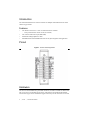
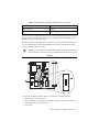
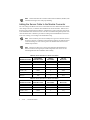
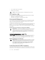
USER MANUAL NI 9757 NI Powertrain Controls O2 Sensor Module Kit - Rev E Contents Introduction .............................................................................................................................. 2 Pinout........................................................................................................................................ 2 Hardware .................................................................................................................................. 2 Powering the Module................................................................................................................ 3 Platform Compatibility ............................................................................................................. 3 Bosch USA LSU 4.x Wide-Band Oxygen Sensor Controllers................................................. 4 Narrow-Band Oxygen Sensor Inputs........................................................................................ 7 Physical Specifications and Characteristics ............................................................................. 8 Electrical Specifications and Characteristics............................................................................ 8 Compliance and Certifications ................................................................................................. 9 Introduction The National Instruments 9757 offers an interface for multiple wide-band and narrow-band exhaust oxygen sensors. Features • 2 Ch. Bosch USA LSU 4.2 or LSU 4.9 wide-band sensor controller • 4 Ch. Narrow-band sensor input (differential) • All channel readings updated at 1 kHz • LabVIEW FPGA and LabVIEW Real Time VIs for quick integration with application – Fuse-protected heater control circuits (serviceable) Pinout Figure 1. NI 9757 Pin Assignments Hardware The NI 9757 Sensor Module Kit (part number 782079-01) includes controllers for Bosch USA LSU 4.2 or LSU 4.9 wide-band oxygen sensors, and inputs for zirconium-dioxide-element, narrow-band oxygen sensors. Wide-band oxygen sensors may also be referred to as Universal 2 | ni.com | NI 9757 User Manual Exhaust Gas Oxygen (UEGO) sensors. Narrow band sensors may also be referred to as Exhaust Gas Oxygen (EGO) sensors. NI recommends using the NI 9923 Connector Kit for connecting to the NI 9757. The NI 9923 provides proper strain relief for NI 9757 connections. Visit ni.com/info and enter Info Code O2MODULE for more information on parts and accessories for the NI 9757. Powering the Module The NI 9757 requires power from each of the following sources: • The CompactRIO backplane male high density DSUB 15-pin (HD15) connector, which mates with the female HD15 connector on the module. This power source provides a regulated 5 V and ground to various digital logic functions. The CompactRIO 5 V source is active whenever the CompactRIO or R Series Expansion Chassis is properly powered. You can power the NI 9757 only at the HD15 connector by plugging it into a CompactRIO or R Series Expansion Chassis. Do not connect the HD15 connector to any other device. • The external DB-37 connector, the terminals of which are labeled BATT (10) and GND (29). A typical power source is an automotive 12 V battery system, but the NI 9757 can accept power from a range of 6 V to 32 V. The LSU 4.x wide-band sensors will only operate when the power supply is in the range of 8 V to 16.5 V. The module is reverse battery protected to -18 V. Without sensors connected and enabled, the NI 9757 requires up to 100 mA from the external supply. The external power source must be capable of powering the sensor heaters, which may require up to 12 A if all channels are in use. Each sensor heater requires approximately 2 A during the first 30 seconds of operation and approximately 1 A thereafter. The UEGO sensor heaters are powered and controlled directly from the NI 9757. The EGO sensor heaters are powered externally and do not require heater control by the NI 9757. The NI 9757 external power ground and CompactRIO backplane power ground are isolated and have no internal connection. The external battery supply input terminals are reverse voltage polarity protected to -18 V. Connecting power to the NI 9757 in reverse polarity at voltages greater than -18 V will result in damage. This event is not covered by the warranty. Caution Platform Compatibility NI Powertrain Control modules require a hardware support system to function. You cannot use the modules independently or interfaced with third-party devices at the backplane HD15 connector. NI Powertrain Control modules are compatible with the following National Instruments platforms: • CompactRIO, which consists of a CompactRIO controller, chassis, or integrated controller/chassis. • NI PXI, which consists of any NI PXI chassis, NI PXI RT controller, and NI PXI-78xxR R Series FPGA card. The NI Powertrain Control modules insert into an NI R Series NI 9757 User Manual | © National Instruments | 3 expansion chassis. Connect an NI R Series expansion chassis to the NI PXI FPGA card using a SHC68-68-RDIO cable. NI Powertrain Control modules are not compatible with the National Instruments CompactDAQ chassis. Note You can use NI Powertrain Control modules with NI cRIO-911x, NI cRIO-907x, and NI R Series Expansion systems under the following conditions: • Leave one empty chassis slot between NI Powertrain Control modules and other NI modules. • Maintain an ambient system operating temperature of 0 °C to 45 °C. Note Typical specifications of National Instruments modules might not apply when used in a system with NI Powertrain Control modules. National Instruments guarantees warranted specifications for all National Instruments modules except thermocouple modules when used in a system with NI Powertrain Control modules. Note National Instruments recommends the NI 9214 for thermocouple measurements in CompactRIO systems using NI Powertrain Control modules. Note Note NI Powertrain Control modules do not support Scan Interface mode, auto-detection, or ID mode. Bosch USA LSU 4.x Wide-Band Oxygen Sensor Controllers The NI 9757 Sensor Module Kit (part number 782079-01) includes two Bosch USA LSU 4.2 and LSU 4.9 Universal Exhaust Gas Oxygen (UEGO) sensor controllers. The NI 9757 controls the pump current, referred to as Ip, to the sensor element to maintain a fixed voltage reference across the element. The exhaust oxygen content and the air-fuel mass ratio are proportional to the controlled sensor pump current. The temperature of the sensor element is also critical to obtain a good exhaust oxygen measurement. The NI 9757 controls the sensor element temperature at 750 °C for LSU 4.2 sensors and at 780 °C for LSU 4.9 sensors. Use only the widely available production Bosch USA LSU 4.2 or LSU 4.9 sensors with the NI 9757 wide-band sensor controllers. The NTK wide-band sensor is not compatible with the NI 9757. 4 | ni.com | NI 9757 User Manual L Table 1. Example Bosch USA Model Numbers for LSU 4.x Sensors Sensor Bosch USA Model Number LSU 4.2 sensor 17014 LSU 4.9 sensor 17025 The NI 9757 does not support mixed UEGO sensor types. If dual UEGO sensors are used, they must be identical. If mixed UEGO sensor types are required, you must use multiple NI 9757 modules, pairing one to each sensor type. By default, the NI 9757 is configured to use the LSU 4.9 sensor. Figure 2 illustrates the top of the circuit card assembly inside the module housing. The switch position for the associated sensor type is labeled next to the switch. Do not attempt to open the module housing or change the switch selection while the module is inserted in a chassis or externally connected to sensors or power. Caution Figure 2. <–LSU4.9 / LSU4.2–> <–LSU4.9 / LSU4.2–> 1 The NI O2 Sensor Kit (part number 782083-01) includes the following components: • Bosch USA LSU 4.9 17025 Sensor • 10 ft, 6-conductor cable with a Bosch USA LSU 4.9 mating connector on one end and unterminated wires on the opposite end • Sensor bung NI 9757 User Manual | © National Instruments | 5 Custom cables must be 6-conductor and 0.65 mm in diameter (22 AWG) with stranded, tinned copper wires and proper shielding. Note Adding the Sensor Cable to the Module Connector The color coding of the Bosch USA LSU 4.x wide-band sensor wires differs from the available color coding in the 10 ft, 6-conductor cable included in the NI O2 Sensor Kit. Tables 2 and 3 show the proper connection between the LSU 4.2 and LSU 4.9 sensor connectors, respectively, to the intermediate cable and to the NI 9757. The NI 9757 module housing label provides wire color information next to the DB-37 pin names according to the standard Bosch USA LSU 4.x sensor wire coloring, not according to the intermediate wiring. Sensor connector pin 2 does not actually have a green wire from the sensor to the sensor-connector. A calibration resistor feeds this connector pin within the sensor connector housing. The color code of green is the standard color for the NI 9757 module IA pin location. Note The LSU 4.2 and LSU 4.9 sensors have identical signal definitions but different connector housings and pin number assignments. The sensors are not interchangeable with the intermediate cable assembly. Note Table 2. Bosch USA LSU 4.2 Sensor Connection Intermediate Cable Wire Color LSU 4.2 Pin Number LSU 4.2 Wire Color UNx (B) Black 1 Black IAx (GN) Green 2 — HTRx+ (GY) Brown 3 Grey HTRx- (W) White 4 White VMx (Y) Blue 5 Yellow IPx (R) Red 6 Red Module Pin Label Table 3. Bosch USA LSU 4.9 Sensor Connection Intermediate Cable Wire Color LSU 4.9 Pin Number LSU 4.9 Wire Color UNx (B) Black 6 Black IAx (GN) Green 5 — HTRx+ (GY) Brown 4 Grey HTRx- (W) White 3 White Module Pin Label 6 | ni.com | NI 9757 User Manual Intermediate Cable Wire Color LSU 4.9 Pin Number LSU 4.9 Wire Color VMx (Y) Blue 2 Yellow IPx (R) Red 1 Red Module Pin Label Narrow-Band Oxygen Sensor Inputs The NI 9757 provides four identical zirconium-dioxide-element, narrow-band (switching) Exhaust Gas Oxygen (EGO) sensor inputs and supports several different types of standard zirconium-oxide-element oxygen sensors, also known as lambda sensors. NI recommends that you use a 4-wire heated universal EGO sensor, such as the Bosch USA 15717. This document discusses EGO sensor wires in terms of standard EGO sensors, which use a standardized wire color code. OEM-specific EGO sensors might use different wire color code. Note 4-Wire Heated EGO Sensors 4-Wire heated EGO sensors have a black and gray wire and two white wires. The black and gray wires provide a differential lambda signal. Connect the black wire to the EGO+ pin of the NI 9757 DB-37 connector. Connect the gray wire to one of the EGO- pins for the associated channel of the NI 9757 DB-37 connector. The two white wires connect to a resistive heater element inside the EGO sensor. The NI 9757 does not provide connections for these wires. Connect these to an external 12 V power source, as shown in Figure 3. You can power the wires through a relay that is energized with the main ignition switch and optionally insert a user-supplied 3 A fuse per sensor. If you are using a non-standard EGO sensor with different wire colorings, you must first identify the two wires that are connected to the heater element by testing for approximately 5 Ω across two of the wires. Any other wire combinations will have a much higher impedance measurement. The remaining two wires are the differential lambda signal wires. You might need to use trial and error to correct the lambda signal wiring polarity. The sensor will not be damaged if the wire polarity is reversed, but the sensor will not provide a correct reading and will likely appear as a cold sensor in the software. Figure 3. 4-Wire Heated EGO Sensor Connection NI 9757 User Manual | © National Instruments | 7 Physical Specifications and Characteristics Weight ...............................................................170 g Maximum Altitude............................................2000 m Maximum Ambient Temperature......................60 °C Operating Humidity ..........................................10% to 90% RH, noncondensing Pollution Degree ...............................................2 Ingress Protection .............................................IP40 For indoor use only. If you need to clean the module, wipe it with a dry towel. Electrical Specifications and Characteristics External Power Input Range...............................................6 to 32 V Input Range for Functional UEGO Sensors ..........................................8 to 16.5 V Reverse Polarity Protection ......................–18 V Input Capacitance .....................................300 µF Inrush Current ...........................................3 A for 1 msec at 13.8 V Consumption No UEGO Sensors Enabled ..............1.3 W at 13.8 V 1 UEGO Sensor Enabled ..................15 W at 13.8 V 2 UEGO Sensors Enabled.................30 W at 13.8 V Maximum Module Power Dissipation, 2 UEGO Sensors Enabled.................................1.4 W at 13.8 V Internal Analog-to-Digital Conversion Range..0 to 4.096 V Internal Analog-to-Digital Conversion Resolution .........................................................12-bit Internal Analog-to-Digital Conversion Rate.....1000 samples/s UEGO Sensor Analog Measurement Hardware Filter .....1st order RC lowpass, 16 Hz cutoff Pump Current (Ip) Measurement Range ...–2.0 to 2.4 mA Pump Current (Ip) Measurement Resolution .................................................1 µA Pump Current (Ip) Measurement Accuracy ...................................................± 0.1 % Lambda Measurement Range ...................0.65 to 15.99 8 | ni.com | NI 9757 User Manual Temperature Measurement Range LSU 4.2............................................. 610 to 1060 °C LSU 4.9............................................. 533 to 1200 °C Resistance Measurement Resolution ........ 0.5 Resistance Measurement Accuracy .......... ± 0.1 % Temperature Control Target LSU 4.2............................................. 750 °C LSU 4.9............................................. 780 °C Temperature Control Effective Heater Voltage Range........................................... 5.0 to 13.0 V Temperature Control PWM Frequency .... 100 Hz Heater Fuse ............................................... Littelfuse part number 0451007.MRL (7 A, 125 V) EGO Sensor Measurement Range ................................. 0.0 to 1.36 V Measurement Resolution .......................... 1 mV Measurement Accuracy ............................ ± 0.1 % Input Over-Voltage Protection .................. –15 to 44 V Safety Guidelines Do not operate the NI 9757 n a manner not specified in these operating instructions. Product misuse can result in a hazard. You can compromise the safety protection built into the product if the product is damaged in any way. If the product is damaged, return it to National Instruments for repair. Caution Compliance and Certifications Safety This product meets the requirements of the following standards of safety for electrical equipment for measurement, control, and laboratory use: • IEC 61010-1, EN 61010-1 • UL 61010-1, CSA 61010-1 Electromagnetic Compatibility This product meets the requirements of the following EMC standards for electrical equipment for measurement, control, and laboratory use: • EN 61326-1 (IEC 61326-1): Class A emissions; Industrial immunity • EN 55011 (CISPR 11): Group 1, Class A emissions • AS/NZS CISPR 11: Group 1, Class A emissions NI 9757 User Manual | © National Instruments | 9 • FCC 47 CFR Part 15B: Class A emissions • ICES-001: Class A emissions Caution When operating this product, use shielded cables and accessories. CE Compliance This product meets the essential requirements of applicable European Directives as follows: • 2006/95/EC; Low-Voltage Directive (safety) • 2004/108/EC; Electromagnetic Compatibility Directive (EMC) Environmental Management NI is committed to designing and manufacturing products in an environmentally responsible manner. NI recognizes that eliminating certain hazardous substances from our products is beneficial to the environment and to NI customers. For additional environmental information, refer to the Minimize Our Environmental Impact web page at ni.com/environment. This page contains the environmental regulations and directives with which NI complies, as well as other environmental information not included in this document. Waste Electrical and Electronic Equipment (WEEE) At the end of the product life cycle, all products must be sent to a WEEE recycling center. For more information about WEEE recycling centers, National Instruments WEEE initiatives, and compliance with WEEE Directive 2002/96/EC on Waste and Electronic Equipment, visit ni.com/environment/ weee. EU Customers ⬉ᄤֵᙃѻક∵ᶧࠊㅵ⧚ࡲ⊩ ˄Ё RoHS˅ Ёᅶ᠋ National Instruments ヺড়Ё⬉ᄤֵᙃѻકЁ䰤ࠊՓ⫼ᶤѯ᳝ᆇ⠽䋼ᣛҸ (RoHS)DŽ݇Ѣ National Instruments Ё RoHS ড়㾘ᗻֵᙃˈ䇋ⱏᔩ ni.com/ environment/rohs_chinaDŽ (For information about China RoHS compliance, go to ni.com/environment/rohs_china.) Battery Replacement and Disposal This device contains a long-life coin cell battery. If you need to replace it, use the Return Material Authorization (RMA) process or contact an authorized National Instruments service representative. For more information about compliance with the EU Battery Directives 2006/66/EC about Batteries and Accumulators and Waste Batteries and Accumulators, visit ni.com/ environment/batterydirective. Battery Directive Cd/Hg/Pb Ferrite Requirement for EMC Compliance Install a clamp-on ferrite bead onto the power supply cable and the signal cable. Power to the module must be off when adding ferrites. Ferrites must be connected to the power cable and to 10 | ni.com | NI 9757 User Manual the signal cable as close to the module as possible. Placing the ferrite elsewhere on the cable noticeably impairs its effectiveness. Determine the clamp-on ferrite beads to install based on your application. Use the following ferrites or other similar ferrites: • Power cable: Laird 28A0592-0A2 (2 total) • Signal cable: Wurth Electronics 7427154 (2 total) Refer to the NI Trademarks and Logo Guidelines at ni.com/trademarks for more information on National Instruments trademarks. Other product and company names mentioned herein are trademarks or trade names of their respective companies. For patents covering National Instruments products/technology, refer to the appropriate location: Help»Patents in your software, the patents.txt file on your media, or the National Instruments Patents Notice at ni.com/patents. You can find information about end-user license agreements (EULAs) and third-party legal notices in the readme file for your NI product. Refer to the Export Compliance Information at ni.com/legal/ export-compliance for the National Instruments global trade compliance policy and how to obtain relevant HTS codes, ECCNs, and other import/export data. NI MAKES NO EXPRESS OR IMPLIED WARRANTIES AS TO THE ACCURACY OF THE INFORMATION CONTAINED HEREIN AND SHALL NOT BE LIABLE FOR ANY ERRORS. U.S. Government Customers: The data contained in this manual was developed at private expense and is subject to the applicable limited rights and restricted data rights as set forth in FAR 52.227-14, DFAR 252.227-7014, and DFAR 252.227-7015. © 2015 National Instruments. All rights reserved. 375007A-01 Jan15