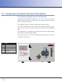
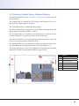
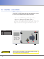
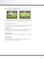
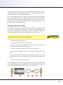
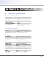
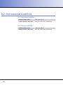
1
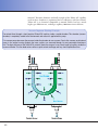
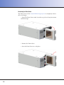
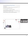
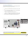
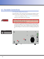
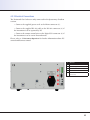
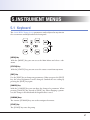
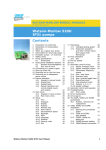
S 9425 HPLC PUMP SYSTEM ISOCRATIC & QUATERNARY GRADIENT VERSIONS USER MANUAL VERSION 1.0 (2012-10-25) 2 TABLE OF CONTENTS Contents 1.Introduction 1.1 How to Use this Manual 1.1.1 Symbols 1.2 Safety Information 1.2.1 1.2.2 1.2.3 1.2.4 General Safety Information Intended Purpose Environmental Safety Electrical Safety 2. Instrument Overview 2.1 General Instrument Overview 2.1.1 Pump Mechanic 2.1.2 Quaternary Gradient Module 3. Instrument Description 3.1 General Instrument Description 3.1.1 Front Panel Description 3.1.2 Back Panel Description 5 5 5 6 6 6 6 6 9 9 9 11 13 13 13 15 5.3.5 Submenu: Degaser Settings 5.3.6 Submenu: Systemmenu 6. Instrument Operation 6.1Overview 6.1.1 Internal Mode 6.1.2 External Mode 6.1.3 Serial Mode 39 6.4 Operating the Pump in Gradient Mode 40 7. Instrument Maintenance 43 6.3.1 Starting the Pump 6.3.2 Stopping the Pump 6.4.1 Starting the Pump 6.4.2 Stopping the Pump 7.1Pumphead 3.3 Quaternary Gradient Version Description 18 21 Appendix A: Compressibility Appendix B: Specifications 4. Instrument Setup 4.1Unpacking 4.2 Capillary Connections 4.2.1 Isocratic Version 4.2.2 Quaternary Gradient Version 4.3 Backside Connections 4.3.1 Drain/Gas Exhaust Connections 4.3.2 Electrical Connections 4.3.3 Remote Connector 5. Instrument Menus 5.1Keyboard 5.2 Status Screen 5.3 Menu Description 5.3.1 Submenu: Pump Menu Pump Settings 5.3.2 Submenu: Pump Menu Run Parameters 5.3.3 Submenu: Pump Menu Calibration 5.3.4 Submenu: Gradient Menu 18 19 21 22 22 23 24 24 25 26 27 27 28 29 30 31 32 33 37 37 37 6.3 Operating the Pump in Isocratic Mode 7.1.1 Pumphead Assembly 7.1.2 Piston Backflushing 7.1.3 Change of Piston Ring 7.1.4 Replacing Check Valves 3.3.1 Quaternary Gradient Version: Front Elements 3.3.2 Quaternary Gradient Version: Functional Elements 37 37 6.2.1 Isocratic 6.2.2 Gradient 16 16 17 37 6.2 Priming the Pump 3.2 Isocratic Version Description 3.2.1 Isocratic Version: Front Elements 3.2.2 Isocratic Version: Functional Elements 34 35 B.1 Technical Specifications B.1.1 Vacuum Chamber (optional) B.1.2 Vacuum Pump (optional) B.1.3 Pump 37 38 39 39 40 41 43 43 44 44 44 47 49 49 49 49 49 B.2 Environmental Conditions 50 Appendix C: Accessories 51 B.2.1 Operational Conditions B.2.2 Storage Conditions C.1 Standard Accessories Isocratic Version Gradient Version Appendix D: Version Control D.1 Version History 50 50 51 51 51 53 53 3 4 1.INTRODUCTION 1.1 How to Use this Manual This manual is designed as a reference to the installation, operation and maintenance of the S 9425 HPLC Pump System. It is strongly recommended to review this manual before operating the instrument. The content of this manual is subject to change without notice. This document is believed to be complete and accurate at the time of publication. The Manufacturer is not liable for any damage resulted from the use of this manual. 1.1.1 Symbols Throughout this manual important text sections are marked with the following symbols: This section includes important information which may result in instrument or personal damage if not carefully followed. This section includes important information for the proper operation of the instrument. Failure to follow this information may result in faulty behaviour of the instrument and/or wrong analysis results. This section emphasis some detailed information intended to optimize the performance of the instrument or to give a better understanding of some technical details. STOP ! ! WARNING NOTE 5 1.2 Safety Information This instrument is compliant with all related standards as stated in Appendix B. 1.2.1 General Safety Information The operation of any analytical instrumentation requires the operator to be familiar with the potential hazards of using chemical solvents. To avoid personal injury and/or damage to the instrument the operator is responsible to follow all safety information herein. The manufacturer assumes no liability for any damage resulted from not following any of these safety procedures. 1.2.2 Intended Purpose This instrument is designed and certified as a general purpose laboratory instrument for research and routine analysis work only. It is not certified for in-vitro or other medical applications. Any use outside this intended purpose does not fall with the manufacturer’s liability. 1.2.3 Environmental Safety Only operate the instrument in well-ventilated areas. If volatile or flammable solvents are used with this instrument, arrange for proper disposal of any waste and/or fumes. Always properly dispose any waste solvents. Avoid open flames and sparks when working with flammable and volatile solvents. In case of instrument leakage, turn off the instrument and remedy the leakage problem immediately. 1.2.4 Electrical Safety Always use the provided power cords. 6 Replace faulty power cords and other cables before operating the instrument. Always replace blown fuses with original spare fuses. When the instrument’s housing is open, electrical connections will be exposed. Disconnect the instrument from the main power before opening the housing. The housing should only be opened by certified service personnel! Damage of the instrument of injury may result from improper handling. STOP ! 7 8 2.INSTRUMENT OVERVIEW 2.1 General Instrument Overview The S 9425 HPLC Pump System is a very flexible and powerful HPLC solvent delivery system. The system is available as Isocratic HPLC pump and Quaternary Low-Pressure Gradient Pump with optional integrated online vacuum degasser. The Quaternary Low-Pressure Gradient version incorporates an active low pressure mixer with adjustable mixing volume. The mixing chamber volume can be freely adjusted. An optional integrated vacuum degasser removes dissolved gases in the mobile phase and prevents air bubbles in the system. 2.1.1 Pump Mechanic The pump mechanic is a robust design for long lifetime and minimal maintenance. Stepper Motor Stepper Motor The is driven by a high-power stepper motor. The stepper motor has a much better resolution in the low-flow range than a conventional DC motor. The stepper motor driven camshaft, driving the pistons is optimized for the typical analytical flow range, especially in the lower flow rate regions. Permanent Lubrication The camshaft and piston drive is permanently lubricated within a sealed chamber. The special lubrication used makes the pump suitable for 24/7 operation. Active Piston Backflushing The optional piston backflushing actively flushed the piston after the primary seals to prevent crystallization of buffer solutions. The piston back- Lubrication The camshaft is constantly lubricated within a sealed chamber to guarantee long lifetime and low maintenance. Optional: Active Piston Backflushing The pump head incorporates an automatic piston backflushing system; this system is interchangeable with old pumps and does not require an additional motor. Dual-Piston Pumphead The pumps use a dual-piston pumphead for low pulsation. Together with electronic pressure compensation the pumps are suitable for all analytical tasks in HPLC and GPC. 9 flushing is incoporporated into the pumphead and does not require any additional pump or motor. Because of this, all pumps are upgradable to active piston backflushing at any time without downtime. Pumphead The short-stroke dual-piston pumphead is optimized for low pulsation and accurate delivery. The S 9425 HPLC Pump System can be fitted with any of the following pumpheads: • Analytical Pumphead (max. Flow Rate 10.000 ml/min) • Micro Pumphead (max. Flow Rate: 4.000 ml/min) • Semi-Preparative Pumphead (max. Flow Rate: 40.000 ml/min) In addition to the performance types above, all pumpheads can be delivered in: • Stainless Steel • PEEK • (Titanium on request) ! 10 WARNING The different pumpheads should not be exchanged freely on a specific pump, as the flow rate is adjusted to a specific type of pumphead. When the pumphead is changed without proper flow adjustment, the flow rate will not be accurate! 2.1.2 Quaternary Gradient Module The S 9425 HPLC Pump System with the Quaternary Gradient option includes a Quaternary Gradient Module. The whole module is mounted inside the pump and consists of several elements. Active Gradient Mixer The active mixer has a variable volume mixing chamber. with a magnetic stirrer unit built-in. The mixing volume can be adjusted freely to optimise mixing performance for different kind of solvents and applications. The solenoid valves of the mixing chamber are high performance valves to achieve very fast and constant switching times. This fast and reliable response of these valves are important for accurate and precise gradient mixing. The solenoid valves hold a system pressure of up to 5 bars which enables the use of gas pressure to be applied to the solvent reservoir bottles without any negative effect on the gradient mixing. Vacuum Pump (Optional) The optional online vacuum degasser consists of a Vacuum Pump and four Vacuum Chambers. The Vacuum Pump is a high-efficiency membrane pump using an advanced Teflon membrane for highest possible chemical compatibility and long lifetime. The specific Teflon membrane is developed for high frequency deformations to achieve an excellent lifetime of the membrane as chances of ruptures are much reduced. Vacuum Chambers The four Vacuum Chambers used in the Quaternary Gradient Module are low-volume, high efficiency chambers using the advanced Teflon AF® Vacuum Pump Vacuum Chambers The Quaternary Gradient Module features an integrated vacuum pump for online degassing. The advanced Teflon membrane guarantees a long lifetime and maximum chemical compatibility. The Quaternary Gradient Module’s 4 vacuum chambers are fitted with high efficiency Teflon AF® tubings for low volume and increased degassing efficiency. Active Mixer Secure Assembly The Quaternary Gradient Module incorporates an active mixer with adjustable volume for optimized gradient mixing. The Quaternary Gradient Module is assembled on a stainless steel tray with a separate drain to protect the instrument in case of leakages. 11 material. The inner diameter and wall strength of the Teflon AF® capillary used in these chambers is optimized for best efficiency with low volume. Teflon AF® is as chemical compatible as normal Teflon, but has a much higher gas diffusion rate, making a capillary 1000 times more efficient. Vacuum Degasser Working Principle The solvent flows through a short length of Teflon AF® capillary inside a sealed chamber. This chamber (vacuum chamber) is completely sealed to the environment and vacuum is applied with a pump. This vacuum pump decreases the pressure inside the chamber to near-vacuum. Due to this vacuum any dissolved gases in the solvent running through the inner capillary are removed through its semi-permeable membrane wall. The high efficiency of the Teflon AF® material allows the usage of a very short length of capillary inside the vacuum chamber. This low dead volume offers a quick solvent exchange and very short equilibration time. 12 3.INSTRUMENT DESCRIPTION 3.1 General Instrument Description 3.1.1 Front Panel Description The front panel of the S 9425 HPLC Pump System consists of three main elements: the TFT Display (1), the Keyboard (2) and the Front Cover (3). The 3” TFT Display shows the current status information and is used with the Keyboard to adjust instrument settings and fully operate the instrument in stand-alone mode without a PC required. The Front Cover has a view panel, so that the important parts (Pumphead and Purge Valve) are always visible to the operator. In case of a leak it can be detected before solvents are leaking out of the bottom of the Front Cover. The Front Cover can be opened to easily access the Pumphead, Purge Valve and capillary connections. # Element 1 TFT Display 2 Keyboard 3 Front Cover 13 Removing the Front Cover The Front Cover of the S 9425 HPLC Pump System is completely removable at its hinges. • Open The Front Cover to 90° (in order to get free of any instrument stacked on top) • Remove the Front Cover • Store the Front Cover at a safe place 14 3.1.2 Back Panel Description The back panel of the S 9425 HPLC Pump System houses the power and interface connectors and several drain outlets. The Power Cord Connection & Power Switch housing holds the main fuse in an internal fuse carrier. The optional Drain Outlet is the leakage drain for the Gradient Mixer Module. The optional Gas Outlet is the gas outlet of the Vacuum Pump where all solvent fumes from the degassing process are exhausted. The digital I/O and other interface connectors are used for remote instrument control and are discussed in a later chapter. # Element 1 Gradient Mixer Module Drain (optional) 2 Vacuum Degasser Gas Outlet (optional) 3 Instrument Serial Number 4 Power Cord Connection & Power Switch 5 Remote Digital I/O Connector 6 RS-232 Interface Connector 7 RS-485 Interface Connectors 8 USB Interface Connector 15 3.2 Isocratic Version Description 3.2.1 Isocratic Version: Front Elements The Isocratic Version of the S 9425 HPLC Pump System has all important parts directly accessible from the front panel when the Front Cover is opened or removed. The Capillary Holder (3) holds the pump inlet capillary in place. The Pumphead (4) is completely accessible from the front to make capillary connections or change pump sealings. The Purge Valve (5) is used for the priming of the pump and also has the pump outlet connection. # Element 1 TFT Display 2 Keyboard 3 Capillary Holder 4 Pumphead 5 Purge Valve 16 3.2.2 Isocratic Version: Functional Elements All functional elements of the S 9425 HPLC Pump System are located inside the instrument. The Display PCB (1) controls the TFT Display and Keyboard. It is accessible when the display panel is removed. The Controlled PCB (2) controls the whole pump. The Power Supply Unit (3) supplies 24V to the PCB’s and pump motor. The input voltage is variable from 90 V to 240 V. The Pump Mechanic (4) drives the pumphead and includes the camshaft, lubrication chamber, driving pistons and the stepper motor. # Element 1 Display PCB 2 Controller PCB 3 Power Supply Unit 4 Pump Mechanic 17 3.3 Quaternary Gradient Version Description 3.3.1 Quaternary Gradient Version: Front Elements The Quaternary Gradient Version of the S 9425 HPLC Pump System has all important parts directly accessible from the front panel when the Front Cover is opened or removed. The Capillary Holder (3) holds the pump inlet capillary in place. The Solvent Inlets Block (4) has an inlet connection for each of the 4 solvents (A, B, C, and D) and also a connection capillary to the Pumphead’s inlet. The Pumphead (5) is completely accessible from the front to make capillary connections or change pump sealings. The Purge Valve (6) is used for the priming of the pump and also has the pump outlet connection. # Element 1 TFT Display 2 Keyboard 3 Capillary Holder 4 Solvent Inlets Block 5 Pumphead 6 Purge Valve 18 3.3.2 Quaternary Gradient Version: Functional Elements All functional elements of the S 9425 HPLC Pump System are located inside the instrument. The Display PCB (1) controls the TFT Display and Keyboard. It is accessible when the display panel is removed. The Controlled PCB (2) controls the whole pump. The Power Supply Unit (3) supplies 24V to the PCB’s and pump motor. The input voltage is variable from 90 V to 240 V. The Vacuum Pump (4) is mounted on a drain tray. It is connected to the Vacuum Chambers (5) and the gas outlet on the back panel. The Vacuum Chambers (5) are mounted on a drain tray and are connected to the vacuum pump and the Controller PCB. The Mixing Chamber (6) is mounted on a drain tray and connected to Solvent Inlet Block on the front panel and the Vacuum Chambers (5). The Pump Mechanic (7) drives the pumphead and includes the camshaft, lubrication chamber, driving pistons and the stepper motor. # Element 1 Display PCB 2 Controller PCB 3 Power Supply Unit 4 Vacuum Pump 5 Vacuum Chambers (4) 6 Mixing Chamber 7 Pump Mechanic 19 20 4.INSTRUMENT SETUP 4.1Unpacking Remove the S 9425 HPLC Pump System from its package and put it on the working desk. Check the instrument thoroughly for any damage that may have occurred during shipping. Contact your supplier in case of any damages. Check the accessories shipped with the instrument if everything is complete and in good condition. 21 4.2 Capillary Connections 4.2.1 Isocratic Version The next step is to make all fluid connections. The following list describes all necessary steps to make the proper capillary connections: • Connect the 1/8” PVDF tubing to the Pumphead inlet (2) • Fix the 1/8” capillaries with the Capillary Holder (1) • Connect a 1/16” capillary (Micro/Analytical = I.D. 0.5mm; SemiPreparatibe = I.D. 0.75mm) to the Purge Valve Outlet (5); this capillary is connected to the autosampler or manual injection valve # Element 1 Capillary Holder 2 Pumphead Inlet 3 Purge Valve Outlet ! 22 WARNING Make sure that the eluent bottles are on a higher level than the pump, so that the solvents can freely flow downwards! 4.2.2 Quaternary Gradient Version The following list describes all necessary steps to make the proper capillary connections for the Quaternary Gradient Version: • Connect the 1/8” PVDF tubings to the eluent inlets A, B, C, and D (2) • A 1/8” PVDF capillary is connected between the Gradient Mixing Outlet (3) and the Pumphead Inlet (4) • Fix the 1/8” capillaries with the Capillary Holder (1) • Connect a 1/16” capillary (Micro/Analytical = I.D. 0.5mm; SemiPreparatibe = I.D. 0.75mm) to the Purge Valve Outlet (5); this capillary is connected to the autosampler or manual injection valve Make sure that the eluent bottles are on a higher level than the pump, so that the solvents can freely flow downwards! # Element 1 Capillary Holder 2 Eluent Inlet A, B, C, and D 3 Gradient Mixing Outlet 4 Pumphead Inlet 5 Purge Valve Outlet ! WARNING 23 4.3 Backside Connections 4.3.1 Drain/Gas Exhaust Connections The Drain Outlet is only connected in the Quaternary Gradient version, while the Gas Outlet is only available with the optional Vacuum Degaser. • Connect the supplied gas tubing (blue colored) to the GAS OUT connector on the backside of the instrument. STOP ! When working with aggressive and/or toxic solvents, make sure that any fumes from the GAS OUT connector is properly disposed of and not evaporated into the working area! • Connect the supplied silica tubing to the DRAIN outlet on the backside of the instrument. In case of a leakage of the Gradient Mixer or Vacuum Degasser, solvent will be leaking through this tubing. Make sure that the liquids are collected in some vessel and properly disposed of. # Element 1 Drain 2 Gas Outlet 24 4.3.2 Electrical Connections The Drain and Gas Outlets are only connected in the Quaternary Gradient version. • Connect the supplied power cord to the Mains connector (1). • Connect the supplied RS-232 cable to the RS-232 connector (3) if the instrument is to be operated by PC • Connect the remote control wires to the Digital I/O connector (2) if the instrument is to be run in External mode. Please refer to 5. Instrument Operation for further information about PC control and Remote control. # Element 1 Mains connector 2 Remote Digital I/O 3 RS-232 Serial Communication 4 RS-485 Communication Bus 5 USB Communication (not in use) 25 4.3.3 Remote Connector Run Input Used to start the pump with the current settings. EXTERN contact (see below) must be closed to activate this feature. Extern Input The EXTERN input contact must be closed for external operation. Inject Input Connection for a manual injection valve. The pump transfer the injection signal to the data system via RS-232. Error Output In case of a pump error, this output is set. REMOTE 26 Pin Function 1 Run Input 2 GND 3 Extern Input 4 GND 5 Inject Input 6 GND 7 Error Output 8 GND 9 N.C. 10 GND 11 N.C. 12 GND 5.INSTRUMENT MENUS 5.1Keyboard The S 9425 HPLC Pump System parameters can be adjusted at any time via the screen menu and keyboard on the front panel. [MENU] Key With the [MENU] key you can access the Main Menu and select a submenu. [STATUS] Key With the [STATUS] key you can access the status screen from any menu. [EDIT] Key Use the [EDIT] key to change any parameters. When you press the [EDIT] key, the selected parameter can be changed. Confirm the new setting by pressing the [EDIT] key again. [CANCEL] Key With the [CANCEL] key you can abort the change of a parameter. When pressing [CANCEL] key instead of [EDIT] key when changing a parameter, the change is discarded and the original value is used. [CURSOR] Keys The 4 arrow [CURSOR] keys are used to navigate the menus. [START] Key The [START] key starts the pump. 27 [STOP] Key The [STOP] key stops the pump. [PURGE] Key The [PURGE] key ([START] and [STOP] together) is used to purge the pump. STOP ! Make sure that you open the Purge Valve before pressing the [PURGE] key. When activated, the Purge will run the pump with maximum flow rate and can damage the column if the Purge Valve is closed! 5.2 Status Screen The Status Screen shows the most important parameters. Mode The top line shows the currently selected mode: Intern, Extern or Serial. Status On the top right the current status is displayed: Stop, Hold, Run, or Error Flow The Flow Rate is shown on the left center area. It always shows the current Flow Rate. Pressure The current pressure is shown in the right center area. The pressure is 28 shown in the selected unit (e.g. Bar, MPa, or PSI). 5.3 Menu Description With the [MENU] key, the Main Menu is displayed. Use the [CURSOR] key ([UP] and [DOWN]) to browse through the Main Menu for access of one of the Submenus. 29 5.3.1 Submenu: Pump Menu Pump Settings Min.Pressure The Minimum Pressure threshold. The pump will stop, if the pressure falls below this threshold. Max.Pressure The Maximum Pressure threshold. The pump will stop immediately, if the pressure rises above this threshold. Max. Pr. Purge The Maximum Purge Pressure threshold. The pump will stop immediately, if the pressure rises above this threshold when the Purge function is used. This a safety feature to prevent column damage when the purge valve is closed while Purge is active. Change Unit The Pressure Unit can be changed here. Available selections are: Bar, MPA, and PSI. All pressure values are shown in this selected pressure units. Compressibility The Compressibility can be changed here. A Compressibility of 1.000 is used for water and 0.700 for Methanol. 30 5.3.2 Submenu: Pump Menu Run Parameters Hold Timeout The Hold Timeout specifies a timeout after which the pump automatically stops when it is currently in Hold. If the Timout is set to 0, this feature is disabled. Delay Time The Delay Time specifies a delay between starting the pump and the pump actually starting. Start Ramp The Start Ramp defines a time in which the flow slowly ramps up when started. Stop Ramp The Stop Ramp defines a time in which the flow slowly ramps down when stopped. 31 5.3.3 Submenu: Pump Menu Calibration Network Address The Network address can be any number between 0 and 15. It is used for specific cases of external control mode. Head The Head settings defines the installed pump head. Head Constant The Head Constant is a setting for an individual pump’s flow rate adjustment. Do not change this value. Pressure Comp. The Pressure Compensation is a setting for an individual pump’s pressure compensation adjustment. Do not change this value. Pressure Zero The Pressure Zero is an offset for the installed pressure sensor. Only change this value when the pressure sensor is changed. 32 5.3.4 Submenu: Gradient Menu Prog. Run Select the Program Number (1-8) which should be run. Prog. Edit Select the Program Number (1-8) to edit (see below). Enter Gradient In this menu the Gradient Program can be edited. The Program Number is selected in the Menu above. Editing Values Each value of a Gradient Program line can be edited with the [EDIT] key and the [UP] and [DOWN] keys. Confirm the change with [EDIT] and cancel the change with [CENCEL] key. Adding Lines A new line can be added by pressing the [EDIT] key when the cursor is in the first (“#”) column. Deleting Lines A line can be deleted by pressing the [CANCEL] key when the cursor is in the first (“#”) column. 33 5.3.5 Submenu: Degaser Settings Degaser Select <ON> or <OFF> to switch the degaser on or off. Mode Select the degasser mode: HYSTERESIS mode switches the dgeasser on and off depending on the vacuum level. In CONTINUOUS mode the vacuum pump runs constantly. Speed The speed of the vacuum can be selected to be either HIGH or LOW. This speed setting has no impact on the degassing performance, just on the time needed to reach the vacuum level. Vacuum Level The current vacuum level is displayed (950 - vacuum chamber pressure). 34 5.3.6 Submenu: Systemmenu Int./Ext./Ser. The Operation Mode can be changed here between Intern, Extern or Serial. Software Display The Software Display is the installed firmware version of the Display PCB. Software Mainb. The Software Display is the installed firmware version of the Controller PCB. 24V Voltage The 24V Voltage is an actual voltage reading for one of the PCB’s controlled voltages. Runtime The runtime shows the total runtime of the pump. 35 36 6.INSTRUMENT OPERATION 6.1Overview The S 9425 HPLC Pump System can be operated in 3 different Operation Modes: Internal, External, or Serial 6.1.1 Internal Mode In Internal Mode the instrument is controlled manually with the Keyboard. 6.1.2 External Mode In External Mode the instrument is controlled via the Remote Digital I/O contacts. 6.1.3 Serial Mode In Serial Mode the instrument is controlled by a PC software (e.g. Clarity) via RS-232 serial line. 6.2 Priming the Pump Before the S 9425 HPLC Pump System can be operated it must be primed with the required mobile phase. 6.2.1 Isocratic • connect the plastic syringe to the purge valve outlet • suck the eluent through the tubing till it starts filling the syringe. • keep the syringe on the purge valve outlet • press [PURGE] and check if the syringe is filling with constant speed Now, the pump is primed and ready for operation. 37 6.2.2 Gradient • connect the plastic syringe to the purge valve outlet • select the channel (A, B, C, or D) you want to prime with the cursor keys ([LEFT] and [RIGHT]) in the Status Screen: A:100 B:0 C:0 D:0 • open the selected channel with the [UP] key A:100 B:0 C:0 D:0 • suck the eluent through the tubing till it starts filling the syringe. • keep the syringe on the purge valve outlet • press [PURGE] and check if the syringe is filling with constant speed Now, the pump is primed and ready for operation. 38 6.3 Operating the Pump in Isocratic Mode 6.3.1 Starting the Pump The S 9425 HPLC Pump System can be started by pressing the [START] key. The pump will run at the selected flow rate. Flow Start Ramp If a time is set for the Start Ramp, the flow rate will slowly increase from 0 to the selected flow rate over a selected time (e.g. Start Ramp time). This feature gently increases flow and therefore pressure and may increase the lifetime of some specific columns. 6.3.2 Stopping the Pump The S 9425 HPLC Pump System can be stopped by pressing the [STOP] key. The pump will stop immediately, unless a Stop Ramp is set. Flow Stop Ramp If a time is set for the Stop Ramp, the flow rate will slowly decrease from the selected flow rate to 0 over a selected time (e.g. Stop Ramp time). Maximum Pressure In case the Maximum Pressure threshold is met, the pump stops immediately. Minimum Pressure In case the Minimum Pressure threshold is met, the pump stops if the pressure stays below the threshold for 30 seconds. 39 6.4 Operating the Pump in Gradient Mode 6.4.1 Starting the Pump The S 9425 HPLC Pump System can be started by pressing the [START] key. The pump will run at the selected flow rate. Flow Start Ramp If a time is set for the Start Ramp, the flow rate will slowly increase from 0 to the selected flow rate over a selected time (e.g. Start Ramp time). This feature gently increases flow and therefore pressure and may increase the lifetime of some specific columns. After the pump reached its flow rate, it automatically goes to HOLD; this means the pump is running, but the gradient program time is on hold. The pump will switch from HOLD to RUN after pressing the [START] key again, or by external signal. 40 The current state of the gradient program can be checked on the Status Screen be pressing the [STATUS] key: The bottom line shows the current gradient composition while the center of the status screen shows the current step, step time and total time. 6.4.2 Stopping the Pump The S 9425 HPLC Pump System can be stopped by pressing the [STOP] key. The pump will stop immediately, unless a Stop Ramp is set. Flow Stop Ramp If a time is set for the Stop Ramp, the flow rate will slowly decrease from the selected flow rate to 0 over a selected time (e.g. Stop Ramp time). Maximum Pressure In case the Maximum Pressure threshold is met, the pump stops immediately. Minimum Pressure In case the Minimum Pressure threshold is met, the pump stops if the pressure stays below the threshold for 30 seconds. 41 42 7.INSTRUMENT MAINTENANCE 7.1Pumphead 7.1.1 Pumphead Assembly The following diagram shows all the components of the dismantled pump head: # Element # Element 1 Pump head body 14 Thrust bolt 2 Piston sealing ring 15 3 Piston guide with piston back flushing Outlet valve housing (pressure side) 16 4 Secondary sealing ring Capillary tube for connecting the damping piston 5 Pressure spring 17 Hollow screws M4x45 6 Ceramic piston assembly 18 Relief valve block 7 Guide bearing 19 Venting screw 8 Centering disk 20 Sealing ring: relief valve 9 Mounting plate 21 10 Hollow screw Capillary for connecting relief valve and pump head 11 Check valve cartridge 12 Inlet valve housing (suction side) 22 Drain capillary from relief valve block 13 Ferrule 1/8” 23 Solvent outlet 24 Pressure sensor 43 7.1.2 Piston Backflushing When using saliferous eluents, a growth of salt crystals is possible behind the piston ring on the ceramic piston. Under unfavorable working conditions, these salt crystals can lead to a higher wearing of the piston ring. Generally, it is sufficient to rinse the rinsing chamber (between piston ring and secondary sealing ring) with distilled water once a week. The water remaining in the rinsing chamber stops the crystallization of salt crystals. Therefore, the lower capillary tubes should be connected together with PTFE tubing so that the water remains in the rinsing chamber. The rinsing of the chamber should be done with the plastic syringe delivered with the instrument. 7.1.3 Change of Piston Ring • Loosen the two hollow screws (10) for removing the mounting plate (9) • take off the guide bearing, piston assembly, pressure springs and centering discs • pull out the piston guide • pull out the piston rings very carefully with the help of a pair of tweezers • completely insert the new sealing rings into the opening (flange upward); the small spring has to show in direction of the pump head • insert the piston guide upward with the secondary sealing ring (white) • put the ceramic piston into the guide bearing, insert the spring with the centering discs in the piston and place the whole unit on the piston guide • put the mounting plate on top and fasten it with the hollow screws (10) • completely push down both pistons by hand for several times in order to check if the pistons were jammed during the process of assembling 7.1.4 Replacing Check Valves The check valves are constructed as cylindrical cartridges. The cartridges have sealing rings, made of PEEK mounted on both sides. 44 These sealing rings have to ensure that the solvent will not bypass the check valve. Both valves, on the high and low pressure side of the pump are identical and therefore can be used for both sides. Place the cartridge in the valve housing and fasten first by hand and then turn another half of a turn by using the 13mm wrench delivered with the instrument. If the pump is not delivering the correct flow rate, the valve housing might not be tightened enough. Before tighter fasting make sure, that the pump was carefully flushed. Cleaning the Check Valve Cartridge Generally, the check valves cartridges don’t wear. However, a deposit of dirt in the valve can influence the function. In this case, only a limited improvement will be achieved when cleaning the fully assembled cartridge. The more dependable method is to dismantle the valve for cleaning. In order to avoid any loss of valve parts, it is recommended to use a small container for the process is dismantling. ! WARNING • pull out both sealing discs (1) • carefully push out the valve contents (3-5) • clean the valve part depending on the degree of dirt either with a washing bottle or with an ultrasonic bath • insert the sealing disc which is next to the ring marker • then insert the sapphire seat with the polished side toward the ruby ball • place the ruby ball in the deeper side of the check guide (5) and put both into the bearing (2) with the ruby ball (4) facing the sapphire seat (3) • press the second sealing disc on top After assembling, check the functioning of the valve by blowing air through it. It is possible to blow the air from this side of the ring marker through the valve and it should lock when blowing the other direction. 45 # Element 1 PEEK sealing ring Valve bearing with ring marker Sapphire seat Ruby ball Check guide made of ceramic 2 3 4 5 46 APPENDIX A: COMPRESSIBILITY A general problem for constant flow delivery with piston pumps is the compressibility of the solvents under pressure. Any liquid shows a specific volume elasticity. If the liquid is influenced by pressure changes Δp, the volume will change by ΔV. The volume V will become the same as before, if the pressure will be reduced to the original value again. The dimension of the change in volume is the compressibility. This can be shown as: Compressibility = relative change of the volume the necessary pressure change therefore: K= -1 V x ΔV Δp The constant volume delivery can be seen as a stepwise displacing of liquid out of the pump head. The dimension for the volume delivery is the amount of piston volume during a period of time. But this is only correct as long as the delivery is done without any added pressure. As soon as the liquid delivery has to be done against a back pressure, a specific amount of the piston volume has to be used for compressing the liquid first, before the actual delivery can start. This can be described by the following diagram: A to B B to C C to D D to A # Element V1 p1 V2 p2 suction volume suction pressure delivery volume delivery pressure suction of liquid during pressure p1 compressing the liquid from p1 to p2 delivery against pressure p2 changing from delivery to suction 47 The compressibility will effect the constant of the liquid delivery depending on the pressure. To overcome this problem, the S 1125 is using a calculation program to correct the pressure depending change of the flow rate. This calculation program corrects the compressibility as well as the always existing leakage rate of the check valves, in relation to the actual pressure. The processor is checking the back pressure every 0.1 seconds and corrects the piston speed accordingly. The calculation program is using the liquid with the smallest compressibility (water) as a factor of 1. As different organic solvents are showing a different compressibility, the processor needs this information for the most accurate delivery rate. This information can be added through the Compressibility Factor in the menu. As water has been normalized to the factor of 1, all others have to be smaller than 1. The following table shows the Compressibility Factors of the mostly used solvents: Solvent Compressibility Water Methanol Ethanol Propanol Butanol Acetonitrile Chloroform Buffer Solutions 1.000 0.630 0.740 0.720 0.750 0.680 0.580 1.000 For solvent mixtures of different organic solvents, the constant can be calculated by adding the constants of the different solvents in relation to their percentage in the mixture. For example: 50% H2O, 20% Methanol, 30% Acetonitril F = 0.5 F(H2O) + 0.2 F (Methanol) + 0.3 F (Acetonitril) F = 0.5 x 1.0 + 0.2 x 0.63 + 0.3 x 0.68 F = 0.83 For other solvents with an unknown factor, an average factor of 0.700 can be used. The difference from the correct delivery rate won’t be higher than 5%. If this accuracy is good enough, a medium factor of 0.700 for all organic solvents and 1.000 for water can be used. 48 APPENDIX B: SPECIFICATIONS B.1 Technical Specifications B.1.1 Vacuum Chamber (optional) # of Channels: Degassing Technique: 1, 2, 3, or 4 Applied vacuum through semipermeable membrane Teflon AF®, Stainless Steel / PEEK* < 500 µl 1.1 mm < 20% dissolved gases remaining in water at 1.0 ml/min* Wetted Materials: Volume per Channel: Inner Diameter (Capillary): Degassing Efficiency: B.1.2 Vacuum Pump (optional) Mechanism: Stepper Motor driven membrane pump Wetted Material (Fumes only): Teflon, Aluminium, EPDM B.1.3 Pump Wetted Materials: Flow Rate: Flow Accuracy: Flow Precision: Gradient Mixing: Pressure Range: Pressure Pulsation: Dimensions: Weight: Power Supply: Stainless Steel / PEEK*, PVDF, Ceramics, Ruby Micro: 0.001 - 4.000 ml/min Analytical: 0.001 - 10.000 ml/min Semi-Preparative: 0.001 - 40.000 ml/min ± 1.0 % @ 1.000 ml / min ± 0.1 % RSD @ 1.000 ml/min Dynamic; 516 - 923 µl adjustable mixing volume 0 – 40 MPa (0 – 6000 PSI) typical < 0.1 MPa or < 1.0 % 310 x 165 x 478 mm (W x H x D) 7.0 kg 100 – 250 ~V, 47 – 63 Hz, 20 W * depending on material option 49 B.2 Environmental Conditions B.2.1 Operational Conditions Ambient Temperature: Ambient Relative Humidity: +10 °C to +35 °C 20 to 80 % RH (non-condensing) B.2.2 Storage Conditions Ambient Temperature: Ambient Relative Humidity: 50 -20 °C to +60 °C 20 to 80 % RH (non-condensing) APPENDIX C: ACCESSORIES C.1 Standard Accessories The S 9425 HPLC Pump System is delivered with the following standard accessories: Isocratic Version • 1x Power Cord (EU Type) • 1x Serial Cable (RS-232) • 1x 1/8” Capillary, FEP (2 m) • 1x 1/8” Fitting & Ferrule, PVDF • 1x 1/16” Capillary, I.D. 0.50mm, 60 cm (SS or PEEK) • 1x Wrench, 12 x 13mm • 1x Wrench, 1/4” x 5/16” • 1x Allen Wrench, 2.5mm • 1x Allen Wrench, 3.0mm • 1x Plastic Syringe w. Tubing Adapter • 1x Operation Manual (this) • 2x Fuse, 2 A Gradient Version • 1x Power Cord (EU Type) • 1x Serial Cable (RS-232) • 4x 1/8” Capillary, FEP (2 m) • 4x 1/8” Fitting & Ferrule, PVDF • 1x 1/16” Capillary, I.D. 0.50mm, 60 cm (SS or PEEK) • 1x Wrench, 12 x 13mm • 1x Wrench, 1/4” x 5/16” 51 • 1x Plastic Syringe w. Tubing Adapter • 1x Operation Manual (this) • 2x Fuse, 2 A 52 APPENDIX D: VERSION CONTROL D.1 Version History The S 9425 HPLC Pump System Operation Manual is subject to version control. The version history is continued and noted on every document. The access to the original document is restricted to the creating party. The document is subject to periodical checks and can never reach an unchangeable state. Version Release Date Description 0.9 2012-07-30 Preliminary Release 1.0 2012-10-25 First Release 53