1
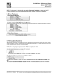
SP Controls 930 Linden Ave. South San Francisco, CA 94080 Phone: 650-392-7880 20 www.spcontrols.com AmpLINC™ System Owner’s Manual July 2012 spcontrols.com Important Safety Instructions 8 Accessories Before using your SP Controls AmpLINC System, please read this Owner’s Manual carefully to ensure optimum trouble-free performance. WARNING: TO REDUCE THE RISK OF ELECTRICAL SHOCK, DO NOT EXPOSE THIS AMPLIFIER TO RAIN OR MOISTURE. DANGEROUS HIGH VOLTAGES ARE PRESENT INSIDE THE ENCLOSURE. DO NOT OPEN THE CABINET. REFER SERVICING TO QUALIFIED PERSONNEL ONLY. The lighting bolt within arrowhead symbol, within an equilateral triangle, is intended to alert the user to the presence of un-insulated “dangerous voltage” within the product’s enclosure that may be of sufficient magnitude to constitute a risk of electrical shock to person. The exclamation point within an equilateral triangle, is intended to alert the user to the presence of important operating and maintenance (servicing) instruction in the literature accompanying the appliance. At the time of this printing, the AmpLINC System accessories were still under development To view the AmpLINC System accessories or to see the full SP Controls product lineup, visit us at: http://spcontrols.com Important Safety Instruction – Please Read Prior to Product Installation. 1. Installation should be performed by a trained and licensed professional to insure safe and lasting operation. 2. All of the safety and operating instructions should be read before the amplifier is installed or operated. Retain these instructions for future reference. All instructions should be followed; all warnings on 2 19 7.2.3 Packaging Instructions (cont.) 1. Please write the RMA number on three sides of the box. Include the SP Controls RMA number inside the box and a brief description of the problem. 2. Do not ship any accessories (manuals, cords, hardware, etc.) with your unit. These items are not needed to service your product. SP Controls will not be held responsible for these items if they are returned with the amplifiers. 3. When shipping your amplifier, it is important that it has adequate protection. We recommend you use the original packing material when returning the product for repair. If you do not have the original box, see number 4. 4. If you provide your own shipping pack, the minimum recommended requirements for materials are as follows: a. 275 P.S.I. burst test, Double-Wall carton that allows for 2-inch solid Styrofoam on all six sides of unit or 3 inches of plastic bubble wrap on all six sides of unit. b. Securely seal the package with an adequate carton sealing tape. c. Do not use light boxes or “peanuts”. NOTE: Damage caused by poor packaging will not be covered under warranty. 3. The amplifier should be situated so that its location and position does not interfere with its proper ventilation. For example, the amplifier must not be placed on a rug, bed, sofa or similar surface that impedes airflow across the chassis. Airflow through the ventilation openings should be unobstructed. 4. This amplifier should not be used near water, for example, near a bathtub, in a wet basement, near a swimming pool, etc. This amplifier is intended to be operated in a controlled indoor environment. 5. Do not place the amplifier near heat sources such as radiators, heat registers, stoves, or other appliances that produce heat. 6. The 24 Volt DC power supply that is supplied with the AmpLINC System may be connected to 120 to 240 VAC, 50-60 Hertz. Do not defeat the ground or polarization of the power plug. 7. Route power cord and other cables so that they are not likely to be walked on, tripped over or stressed. Pay particular attention to condition of cords and cables at plugs and at the point where they exit the amplifier. To prevent risk of fire or injury, damaged cords and cables should be replaced immediately. 8. Clean the amplifier with a clean, damp cloth. Do not use solvents or abrasive cleaners. Never pour any liquid on the amplifier. 9. When left unused for a long period of time, the power cord should be unplugged form the outlet. 10. Damaged Amplifiers requiring service should be repaired by a qualified service technician when: a. b. c. d. e. The power cord or AC plug has been damaged. Objects have fallen, or liquid has spilled into the unit. The amplifier has been exposed to rain or other moisture. The amplifier does not appear to operate normally or exhibits a marked change in performance. The amplifier has been dropped or the enclosure damaged. 11. The user should not attempt to service the amplifier beyond that described in the operating instructions. All other servicing should be referred to qualified service personnel. 18 3 Table of Contents Important Safety Instructions ················································ 2 Table of Contents ······························································· 4 1 Welcome ········································································ 5 2 System Overview ···························································· 6 3 System Installation ··························································· 8 4 Operation ·······································································12 5 Troubleshooting ······························································14 6 Technical Specifications ··················································15 7 Warranty Statement ·······················································16 8 Accessories ··································································16 7.2.1 Return Authorization Number All returns to the factory for service must be accompanied by a Return Manufacturer Authorization (RMA) number. One can be obtained by contacting SP Controls at (877) 367-8444 or via email at: [email protected] NOTE: Any defective products received without an RA number will be returned to sender at their expense. If SP Controls is unable to contact the sender within 14 days, the merchandise will be considered scrap and may be disposed of. 7.2.2 Shipment Instructions If SP Controls requests that you ship the defective product back to their service center, please refer to the guide below. To ensure prompt warranty service, be sure to follow all instructions. 1. RMA number is required for product being sent to the factory for service. 2. See packing instructions in section 7.2.3. 3. Ship the defective product using a method which provides for order tracking or order confirmation. The service center is located at the following address: SP Controls 930 Linden Ave. South San Francisco, CA 94080 4. Use a bold black marker and write the RMA number on three sides of the box. 5. Record the RMA number for future reference. The RMA number can be used to check the repair or replacement status. 7.2.3 Packaging Instructions Should SP Controls request that you ship your product to their service center, these instructions must be followed in order to ensure safe delivery. If they are not followed, SP Controls assumes no responsibility for damaged goods and/or accessories that are sent with your unit. 4 17 7 Warranty Information 6.1 Warranty Summary All SP Controls amplifiers and accessories, unless excluded in this summary, are covered by a 3-year limited warranty on parts and labor from the date of purchase. In order to be eligible for warranty repairs, the amplifiers and accessories must have been purchased through an authorized SP Controls dealer and submitted by the original purchaser. This warranty is only valid in the country in which the amplifier was purchased. 7.1.1 Eligibility Requirements. SP Controls warrants against all malfunctions which come as a result of component or manufacturer defect. The amplifier is also covered from all failures which arise during the warranty period (3 years from date of purchase) that are not a result of misuse. The following actions will void your warranty: The power cord or AC plug has been damaged through misuse. The amplifier has been exposed to moisture or extreme temperatures. The amplifier has been dropped, items have been dropped on the amplifier, or the enclosure has been damaged. The amplifier has been opened by the operator. The amplifier was improperly packaged when sending to the factory for repair, resulting in damage. Any of the precautions or instructions found in this manual were not followed. Damages resulting to the amplifier which are not covered under this warranty can be factory-repaired at cost to the customer. Use the contact information below to initiate the repair process. 7.2 Return Procedure This section includes the return procedures which must be followed in order to prevent processing delay or cost to the cus16 1 Welcome Congratulations on the purchase of your new SP Controls AmpLINC System. If after reading this manual you should have any questions concerning amplifier installation and operation, please contact your Authorized SP Controls dealer, or you may contact us directly using the contact information provided on the back of this manual. 1.1 Features Your AmpLINC System is the result of years of experience in the design and manufacture of quality electronics. As such it provides a combination of performance and operational benefits that simply cannot be found in conventional amplifiers. Distributes audio and power over Cat5 cables Compact hub and subcompact nodes Nodes have selectable wattage and channels Efficient Class D microamplifier inside every node Clean full–range dynamic power Signal Sense Technology for Energy Star Compliance Easy to install distributed audio solution External inline power supply 1.2 Using this Manual In order to obtain maximum performance from your AmpLINC System, please take time to read this brief owner’s manual and carefully follow the guidelines for connection and operation. This manual provides you with the information necessary to safely install and operate your new AmpLINC System in the most common scenarios. If you find yourself requiring additional assistance, please feel free to contact your Authorized Dealer, or you may contact us directly using the information provided on the back of 5 2 System Overview 6 Technical Specifications SP Controls reserves the right to change features and specifications without notice. Maximum Output 20Hz - 20kHz The AmpLINC System by SP Controls consists of two key components: the AmpLINC Hub and the AmpLINC Puck. Other components such as Cat5 cable and speakers play a role in the system, but will not be the focus of this manual. 2.1 System Components & Dimensions Output per node 10W @ 8Ω Hub’s Total Output Wattage of power supply Frequency Response (+0, -3 dB) 20Hz-20kHz THD+N <0.1% at 1W Signal to noise ratio >100dB Standard Voltage Gain Adjustable 20-36dB Input Impedance (Unbalanced) 9-60kΩ (Depending on gain) Sleep, Idle (No Nodes) 0.005/0.016A Class D Input Connectors 3.5mm Stereo, Dual RCA Output Connectors RJ-45 (Hub), Bare wire (Puck) Power Supply External In-Line 24VDC Cooling Convection-Cooling Controls Master Volume (Hub), Gain and Channel Select (Puck) LED Indicators Power & Signal Present Construction Aluminum Chassis (Hub), ABS Plastic (Puck) Dimensions 6 Height 1.25in (3.2cm) Width 4.35in (11.1cm) Depth 3.2in (8.1cm) Weight 0.37bs (0.16kg) 15 5 Troubleshooting 2.2 Example System Setup Problem: Hub’s Power indicator does not turn on. Procedure: Check that the Hub is plugged into a live outlet. After you have ensured that it is not a power issue, check that you have a hot signal going into the inputs. If a signal is not detected, the hub will go into a sleep mode after 5 minutes to comply with Energy Star. Problem: AmpLINC Puck’s power indicator does not turn on. Procedure: First check to make sure that the power indicator is lit on the Hub, if not then see the corresponding Troubleshooting entry. If this does not resolve the issue, then double-check the Cat5 cable going from the Hub to the amplifier Puck. Replace this cable if possible. If this is not the issue, then ensure that you are not stringing too many Pucks on one line. Refer to section 3.2.2 for more information on this. Problem: AmpLINC Puck is outputting no audio. Procedure: First check that the signal indicator on the Hub is lit and the volume control is at a reasonable level on the hub. Next, to rule out a cabling issue, check that the power indicator is lit on the amplifier node. If this does not resolve the issue then refer to section 3.2.2 to ensure that the DIP switches are correctly configured on the node. If all of the channel selection switches are in the “up” position, then this is most likely the issue. Refer to section 3.2.2 for the proper settings. Problem: AmpLINC Puck is outputting weak audio. Procedure: First check the Level knob on the Hub to make sure it is at a reasonable level. Next, check the DIP switches on the front of the Puck to see what the gain is set at. If both switches are in the “up” position and you still have a weak output, check to 14 7 3 System Installation CAUTION: Before installing your system, make sure that you have read the Important Safety Precautions at the beginning of this manual. 3.1. Hub Installation 4.2.2 Indicators and Controls on AmpLINC Puck Each AmpLINC Puck has an amber LED on top which will illuminate when power is supplied to the from the Hub. Note - When the AmpLINC Hub is in sleep mode, the amber LED indicators on the top of the Pucks will turn off. To control the wattage of the amplifier Puck, refer to section 3.2.2. The AmpLINC Hub is a UL 2043 plenum-rated unit which can be safely installed in the plenum space. SP Controls recommends that the unit is secured in some fashion to prevent movement of the unit if one of the cables is pulled during installation of an amplifier node. For full UL 2043 (Plenum) compliance, the external power supply should be placed in an area other than a plenum space. 3.1.1 Input Connections The AmpLINC Hub accepts an unbalanced stereo input using either RCA or 3.5mm plugs. The standard wiring is shown below. 8 13 4 Operation 4.1 Operating Precautions 1. Before use, your amplifier must be configured for proper operation, including input and output wiring hookup. Improper wiring can result in damage to equipment or potentially harm to the operator. Consult section 3 for setup instructions. 2. Tampering with the circuitry, or making unauthorized changes is not only dangerous but may also violate local regulations. 3. Use care when making connections between the amplifier and the input or output equipment. Using equipment that is not capable of handling the output wattage may lead to permanent damage. NOTE: SP Controls will not be held responsible for damage to your AmpLINC System or connected equipment if the instructions in this manual are not followed. 4.2 Indicators and Controls 4.2.1 Indicators and Controls on AmpLINC Hub The AmpLINC Hub accepts all inputs and power and sends it down Cat5 cable to the AmpLINC Pucks. All power and system volume can be controlled on the Hub. Two LED indicators on the left-hand side of the AmpLINC Hub will illuminate when power is supplied (Power LED - blue) and when signal is detected on either input (Sig LED - green). If the nodes are not outputting any audio, first check to make sure that both of these LEDs are illuminated. Note - When the AmpLINC Hub goes into sleep mode due to no signal, the LED will turn OFF. To turn the AmpLINC Hub back on, make sure that signal is being sent to the Hub. The system volume can be set using the recessed knob on the left -hand side of the unit. To turn this, insert a small screwdriver into the slot and turn clockwise to turn the volume up. 12 3.1.2 Output Connections The AmpLINC Hub utilizes standard Cat5 cable to send both signal and power to the nodes connected to its ports. Regular Cat5 patch cables may be used, purchased in standard lengths or cut and crimped for the installation. If making your own cables, standard A or B patch cable wiring can be used or straight through connections between pin 1-8 to pin 1-8 on either end. Crossover cables or wiring cannot be used. Each port is capable of outputting a maximum of 20 total watts of power to the nodes daisy chained on that port. CAUTION: Do not connect the Hub or Pucks to any other devices (such as a network router or switch). They are not Ethernet capable and will damage other devices. The total power output of the AmpLINC Hub is limited by the power rating of the power supply which was purchased with the system, and cannot exceed 80 Watts. Each AmpLINC Hub port is capable of outputting a maximum of 20 watts of speaker power. This 20 watts is available for the AmpLINC Puck and speakers daisy chained to the port. If you would like to upgrade the chosen power supply, please contact your local sales rep for details. 3.2 Node Installation Each AmpLINC Puck contains a single channel micro amplifier capable of delivering up to 10 watts of power to a single speaker. If you have the SP-IC4 or SP-IC5 speakers as a part of your AmpLINC System, the Puck can be secured to the top of the speaker. To secure the amplifier node, place the node on top of the speaker inserting the screws on the top of the speaker into the notches on the rear of the amplifier. Twist the node clockwise and it will lock into place. 9 3.2.1 Node Input Connections Gain Configuration The AmpLINC system utilizes Cat5 to send power as well as a stereo signal to each node on the line. For the initial connection between the AmpLINC Hub and an AmpLINC Puck, a Cat5 cable should connect any port on the Hub with either the left or right port of the node. The remaining port of the node can be used to daisy chain it to another node. Caution: Do not connect the final Puck in a line back to the AmpLINC Hub. Doing so may damage the Hub. 3.2.2 AmpLINC Puck Configuration The Pucks are configured on an individual basis using the DIP switches located on the front of the node. This can be done with a small screwdriver or other tool that will fit into the recessed switches. The configuration options are found printed on the top of the Puck below. The gain level on the Puck is adjustable from 0.3W to 10W using the DIP switches on the front of the unit. Using the table printed on the top of the node or provided for you on the left, adjust the first 2 DIP switches to the desired setting. Note: Each port from the hub is capable of supplying 20W each. This means that the higher the gain setting, the fewer units you can daisy chain. Refer to the table below. Selected Wattage # of Units/Port 10W 2 4.5W 4 1.0W 15* 0.3W 50* *Number reduced to account for power loss over cable Channel Configuration When the signal is sent down the Cat5 cable from the Hub to the Pucks, both the left and right channels are sent. This means that each AmpLINC Puck can be configured to output the left channel, right channel, or a mono summation. The last 4 switches of the DIP switch are for selecting the channel. Refer to the image in section 3.2.2 or the silkscreen of the amplifier node for switch configurations. Note: Each port from the Hub is capable of supplying up to 20W each. This means that the higher the gain setting, the fewer units you can daisy chain. Refer to the table below. 10 11