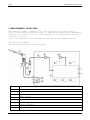
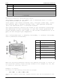
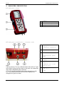
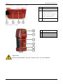
1
EiUK USER MANUAL RASI 700 2 EiUK USER MANUAL RASI 700 Operation Manual – Please carefully read and follow all instructions before operating the analyzer. 1 Table of contents 1 TABLE OF CONTENTS ................................................... 3 2 INTRODUCTION ........................................................ 9 2.1 The RASI 700 ...................................................... 9 2.2 Important general information (EN 50379) and VDI 4206 ............. 9 2.3 Important information about the users/operation manual ............ 9 3 SAFETY INFORMATION ................................................. 11 3.1 Safety regulations ............................................... 11 3.2 Specific safety regulations ...................................... 11 4 4.1 5 RETURNED GOODS ..................................................... 12 Return of hazardous waste ........................................ 12 MEASUREMENT PRINCIPAL .............................................. 13 5.1 Gas flow diagram ................................................. 13 5.2 Electrochemical measured principle ............................... 14 6 ANALYZER DESCRIPTION ............................................... 16 6.1 Analyzer front ................................................... 16 6.2 Analyzer Connectors - bottom side ................................ 16 6.3 Analyzer Connectors - top ........................................ 17 6.4 Analyzer Back .................................................... 17 6.5 Condensate separator ............................................. 18 7 7.1 8 ACCESSORIES ........................................................ 19 Gas sampling probes .............................................. 19 OPERATING THE ANALYZER ............................................. 20 8.1 The Display ...................................................... 20 8.2 The Keypad ....................................................... 20 8.3 Menu configuration ............................................... 21 3 EiUK 9 USER MANUAL RASI 700 FIRST USE OF THE INSTRUMENT ........................................ 22 9.1 Analyzer ready for operation ..................................... 22 9.2 Analyzer settings ................................................ 22 9.3 Setting time and date ............................................ 24 9.4 Configuration of measurement program ............................. 9.4.1 Setting the CO ppm limit values ............................... 9.4.2 Fuel type selection and O2 reference .......................... 9.4.3 User definable fuel types ..................................... 9.4.4 Configuration of the measurement window (display content) ..... 9.4.5 Configuration of the zoom function ............................ 9.4.6 Change measurement program names .............................. 9.4.7 Select core flow search ....................................... 25 25 26 27 28 28 28 29 10 MAINTENANCE ...................................................... 29 11 PREPARATION FOR EACH MEASUREMENT ................................. 29 11.1 Power supply ..................................................... 29 11.2 Auto Off ......................................................... 29 11.3 Measurement with battery charger/battery charging ................ 29 11.4 Measurement with battery (Battery monitoring) .................... 29 11.5 Operation temperature ............................................ 30 11.6 Condensate separator ............................................. 30 11.7 Connectors and leak tightness .................................... 30 11.8 Power ON and zeroing ............................................. 31 12 HOW TO TAKE A MEASUREMENT ........................................ 32 12.1 Selection of the measurement program ............................. 32 12.2 Core flow search ................................................. 33 12.3 Measured Value Display ........................................... 34 12.4 Non-continous draft measurement .................................. 35 12.5 CO purging (optional) ............................................ 36 12.6 CO/H2 and BigCO (optional) ....................................... 36 12.7 Test program ..................................................... 37 12.8 Temporary buffer ................................................. 38 12.8.1 Set values into temporary buffer .............................. 38 12.8.2 To bring values back from the temporary buffer ................ 38 12.9 Storage the measuring results .................................... 39 4 EiUK USER MANUAL RASI 700 12.10 Printing the measurement results ............................... 39 12.11 End of measurement ............................................. 39 12.12 Last measurement results ....................................... 41 12.13 Pressure measurement ........................................... 41 12.14 Flow measurement (optional) .................................... 43 12.15 Differential temperature measurement ........................... 45 12.16 External HC detector (optional) ................................ 12.16.1 Operating HC-detection ...................................... 12.16.2 Setting alarm threshold and zreo point setting .............. 12.16.3 Print-out ................................................... 13 45 46 46 47 DATA STORAGE ..................................................... 48 13.1 Organisation of the data memory .................................. 48 13.2 Information about the data memory ................................ 48 13.3 Site administration .............................................. 13.3.1 View and search sites ......................................... 13.3.2 New entry and change of sites ................................. 13.3.3 Delete sites .................................................. 48 49 50 51 13.4 Data transfer via SD Card (Option) ............................... 13.4.1 Import of Sites ............................................... 13.4.2 Export of Sites ............................................... 13.4.3 Export of Flue Gas Measurements ............................... 13.4.4 Export of Differential Pressure Measurements .................. 52 52 53 53 54 13.5 Measurements in the data memory .................................. 13.5.1 View measurements ............................................. 13.5.2 Delete measurements ........................................... 13.5.3 Export measurements to a SD card (optional) ................... 54 54 55 56 14 EXTRAS / ADJUSTMENTS ............................................. 57 14.1 Service values ................................................... 57 14.2 Maintenance adjustment menu ...................................... 58 14.3 Manufacturer default settings .................................... 58 14.4 Analyzer info .................................................... 59 14.5 Leak proof test .................................................. 60 15 TECHNICAL SPECIFICATIONS ......................................... 62 16 APPENDIX ......................................................... 64 16.1 Text input ....................................................... 64 16.2 Asking the user for a decision (pop up window) ................... 64 5 EiUK USER MANUAL RASI 700 16.3 Datatransfer with Bluetooth (optional) ........................... 16.3.1 PDA-interface Bluetooth ....................................... 16.3.2 PC-interface Bluetooth ........................................ 16.3.3 Spezification ................................................. 66 66 66 68 16.4 Using the USB-Port ............................................... 68 16.5 Analysis and calculations ........................................ 72 16.6 EG –Declaration of confirmity .................................... 73 6 EiUK USER MANUAL RASI 700 Inspect Shipment for Damage Carefully inspect the entire shipment for damage in the presence of the shipper’s agent, removing packaging material if necessary. Note any damage to packaging and/or goods on Packing List and have it signed by the shipper’s agent prior to accepting the shipment. Submit damage claim to EIUK immediately. NOTE: Damage claims not received by EIUK within 3 days of receipt of shipment will not be accepted. Important notice! This high quality electronic analyzer utilizes batteries that discharge even when the analyzer is not in use. Therefore it is very important to charge the batteries every 4 – 6 weeks, even if the analyzer is not in use. When it is fully charged, the analyzer should be switched on and allowed to zero itself before being switched off again. (see chap. 11.8) Failing to properly charge the batteries will void your warranty! Save the original box and the packing material for use if the analyzer must be shipped in the future. The products described in this manual are subject to continuous development and improvement and it is therefore acknowledged that this manual may contain errors or omissions. EIUK encourages customer feedback and welcomes any comments or suggestions relating to the product or documentation. Please forward all comments or suggestions to the Customer Feedback Department at the following address: Eurotron Instruments (UK) Ltd Unit 13 Riley Close Royal Oak Industrial Estate Daventry, NN 11 8QT T: +44 (0)1327 871044, F: +44 (0)1327 301255 E: [email protected] www.eurotron-uk.com This manual is intended solely as a guide to the use of the product. 7 EiUK USER MANUAL RASI 700 EIUK shall not be liable for any loss or damage whatsoever arising from content errors or misinterpretation of information’s from this manual or any mis-use resulting from the use of this manual. 8 EiUK USER MANUAL RASI 700 2 Introduction 2.1 The RASI 700 The RASI 700 flue gas analyzer is used for: • Precise flue gas • Short control of measurements stacks, kilus, furmances and many other sites. measurement of almost any type of combustion It can also be used (when optionals are activated or external equipment is used) for a number of measurement tasks, such as: • Flow velocity measurement of flue gas • Differential measurement of pressure and temperature • Combustibles detection with external HC sensor You will find a list of all optionals for this analyzer on our web page or you can contact EIUK or our local representative. The RASI 700 Analyzer is available in different versions. This manual will describe all versions indicating optionals and features not always available on all versions. 2.2 Important general information (EN 50379) and VDI 4206 This analyzer is not designed to be used for continuous measurements. Before using the analyzer verify the condition of the various parts of the analyzer, such as the probe, the ambient air conditions, the condensate separator, star filter and the connectors for damage and/or blockages. When starting up the analyzer it will take between 1 – 3 minutes to set to zero depending on the condition of the sensors and of ambient. The minimum zeroing time of the analyzer to achieve correct measurement values can be expected by 1.5 minutes! Caution: Exposure to acids; aggressive gases such as sulphur; vapours such as thinners, gasoline, alcohol and paint, etc. can damage, reduce the life of, or destroy the sensors. The life of the sensors depends on how they are used, maintained and treated. Typical average life expectations are: O 2 - 2 years; CO - 2 - 3 years; NO - 3 years, NO2 and SO2 approx. 2 – 3 years. The use of the analyzer for regulatory purposes is subject to special regulations (for example a periodical examination of the analyzer). Please obtain the appropriate regulations from your local responsible authority. 2.3 Important information about the users/operation manual The users/operation manual is an important part of this delivery. It will explain how to use this analyzer properly and sets forth safety and environmentally friendly procedues. It is the responsibility of all users to read and familiarize themselves with this manual, paying particular attention to the safety instructions. 9 EiUK USER MANUAL RASI 700 The most important safety details are listed in chapter 3 (Safety Information). Additional safety details in other chapters are clearly marked with an attention sign. 10 EiUK USER MANUAL RASI 700 3 Safety Information The following safety procedures must to be followed at all times. They are a significant and essential part of this manual. Failure to follow safety procedures can result in the loss of your warranty claims. 3.1 Safety regulations 1. The RASI 700 analyzer may only be used as indicated in this manual. 2. Our analyzers are checked according to the following regulations: VDE 0411 (EN61010) and DIN VDE 0701 before they leave the EiUK factory. 3. EIUK technical products are designed and manufactured according to DIN 31000/ VDE 1000 and UVV = VBG 4 of the professional guilds for fine mechanics and electrical engineering. 4. EiUK assures that the analyzer complies to the essential requirements of the legal regulations of the member states of the electro-magnetic compatibility (89/336/EWG) and to the low-voltage regulations (3/23/EWG). 3.2 Specific safety regulations 1. Use only the battery charger supplied with the analyzer for this instrument 2. No part of the analyzer, including the metal probe tube and all other metal parts & accessories are to be used as electric conductors. 3. The analyzer is not to be used in or under water. 4. The analyzer is not to be placed near or directly exposed to open fire or heat. 5. The specified probe temperature range is not to be exceeded, as the probe, temperature sensory mechanism and sensor could be damaged or destroyed. 6. The analyzer shall void dropping. 7. Caution: Moisture, being pumped out of the condensates trap can be slightly acidic. In case of skin contact IMMEDIATELY: clean affected parts of the body. Avoid getting liquid in eyes. Please carefully clean all parts that come into contact with the condensates. 8. After measurement, vent the analyzer with ambient air and allow the probe to cool. A hot probe could cause burns or ignite flammable material. 9. The fumes from certain materials (for. example, cleaners, petrol, spirit, varnish) may damage the sensors of the ana11 EiUK USER MANUAL RASI 700 lyzer. Do not store or use these or other similar fluids near the analyzer. Your quality management EiUK 4 RETURNED GOODS Packing regulation of 12.07.1991 If your local waste facility does not except EIUK packing materials for disposal, you may return it to EIUK or our local sales representative. Packing materials returned to EIUK must be returned prepaid. 4.1 Return of hazardous waste - Waste Disposal/Returns/Warranty EiUK is required to accept the return of hazardous waste such as electrochemical sensors that cannot be disposed of locally. Hazardous waste must be returned to EIUK prepaid. Return of analyzer according to ElektroG: EiUK is required to accept the return, for proper disposal, of all analyzers delivered after 13th of August 2005. Analyzers must be returned to EIUK prepaid. 12 EiUK USER MANUAL RASI 700 5 MEASUREMENT PRINCIPAL The analyzer draws a sample of the flue gases from the duct using a built-in gas pump through the probe is cleaned and dryed using condensate separator with built-in filter and analyzes the extracted gas with electrochemical sensors. Draft and temperature are measured at the tip of the sampling probe. 5.1 Gas flow diagram Gas flow diagram with CO purging pump Position Description 1 Sampling probe 2 Triple hose 3 Condensate separator 4 Star filter 5 Non return valve 6 Gas pump 7 Sensor chamber 8 O2-Sensor 13 EiUK USER MANUAL RASI 700 9 2. sensor 10 3. sensor 11 4. sensor 12 5. sensor 13 CO Purge pump 11 Pressure sensor * * optional 5.2 Electrochemical measured principle The oxygen content of the sample gas is measured with a 2 electrode electrochemical sensor. Toxic gases like carbon monoxide (CO), nitrogen oxide (NO), nitrogen dioxide (NO 2 ), sulphur dioxide (SO 2 ), and hydrogen sulphide (H 2 S) are measured with 3 electrode sensors. The electrochemical sensors are based on gas diffusion technology. The advantage of this technology is that the signal generated is direct proportionally and linear to the volume concentration (% or ppm) of the analysis gas components. The 3 electrodes are: S (sensing electrode), C (counter electrode) and R (reference electrode). Pos. 1 Sample gas 2 Particle filter 3 Sensing Electrode 4 Reference Electrode 5 Counter Electrode 6 Connection pin 7 Electrolyte reservoir 8 Electrolyte 9 Capillary diffusion barrier When the gas being measured contacts the sensing electrode, it reacts on the electrode surface either through oxidation (for example CO, SO 2 , NO) or reduction (like NO 2 , and Cl 2 ). Example: CO sensor: CO reacts at the sensing electrode as follows: CO + H 2 O -> CO 2 + 2H+ + 2e- and at the counter electrode, oxygen from air will be re-oxidized to water: 14 EiUK USER MANUAL RASI 700 ½ O 2 + 2H+ + 2e- -> H 2 O The sensor supplies a constant current signal (µA-range) that is monitored and analyzed. The current intensity is dependant upon the volume concentration of the sample gas, while other parameters like temperature and cross sensitivity are calculated by the analyzer. 15 EiUK 6 USER MANUAL RASI 700 ANALYZER DESCRIPTION 6.1 Analyzer front 1 Display 2 Condensate separator 3 Key pad 1 Sampling probe connection 6.2 Analyzer Connectors - bottom side Condensate separator Note: If during zeroing T air (5) is disconnected, then value of T gas at the end of zeroing will be used. In this case, the measuring value will be displayed green coloured. If T air (5) will be connected during the measurement, then true T air measurement will occur and the display color changes from green to black. 16 2 Pressure connection 1 (Draft) 3 Pressure connection 2 (Differential pressure) 4 Connector AUX (optional) 5 Temperature connection 1 / T-Ambient air (combustion air) 6 Temperature connection 2 / T-gas EiUK USER MANUAL RASI 700 6.3 Analyzer Connectors - top 1 Cover 2 IR-interface 3 SD-card reader (only by using a EIUK-SD-CARD we can assure the compatibility of all analyzer functions) 4 USB-port and charging port 6.4 Analyzer Back 1 Fixing magnets 2 Gas outlet 3 Handle strip 4 Analyzer feet Important! During measurement the gas outlet must not be covered 17 EiUK USER MANUAL RASI 700 6.5 Condensate separator Remove the condensate separator by pulling it towards you (1) out of the groove of the RASI 700 housing, then pull it downwards (2). The condensate show glass is screwed into the plug. The complete condensate separator can easily be taken apart for cleaning or for exchanging the star filter. (Condensate separator details are included in the service manual) After cleaning a leaknes check (see chap. 14.5) must be done! 18 EiUK USER MANUAL RASI 700 7 ACCESSORIES 7.1 Gas sampling probes The RASI 700 is available with different probes, both with fixed and exchangeable probe tubes. A complete list of available probes can be found in the current price list of this analyzer. Below are two different probe types: Probe ST Probe SF With 180 mm probe pipe (fixed) probe pipe and 1,5 m sampling line With 300 mm exchangeable and 2,7 m sampling line 1 Probe tube 2 Probe cone ( high grade steel) 3 Triple hose (NBR or Viton) 4 Connector for sample gas measurement 5 Connector for draft measurement 6 Connector for temperature measurement 19 EiUK USER MANUAL RASI 700 8 OPERATING THE ANALYZER 8.1 The Display All information required to operate the analyzer is displayed as shown below. 1 Menu bar 2 Function key bar 3 Display panel - Menu - Measurement value - … 4 Zeroing active 5 SD-Card in the slot - Indication green Read- and write access - Indication yellow only Read access (SD-Card write protected) 6 Battery charge condition 8.2 The Keypad Description and function of the keys: ON/OFF Function Keys Menu Key ESC Key Arrow Keys OK Key Press to start the analyzer without delay. The power off function will be delayed to protect the sensors. If there is not enough ambient air the analyzer will recommend the purging of the sensors. Activates the functions seen on the display (2 function key bar) Will show all available functions in the window that is currently in use – also those which have an individual key on the key pad like the printer and the three function keys. Abort or return to the menu above Jump in between lines, change values Confirmation key, select a marked menu 20 EiUK USER MANUAL RASI 700 point Activates the printer function in the measurement and service window. Printer Key 8.3 Menu configuration The RASI 700 organizes all available actions in three main menus: • Menu Measurement all tasks for the measurement programs of the analyzer. Here you can select all installed and available measurement programs. • Menu Memory all tasks for the management of the data memory available. • Menu Extras all the other available tasks – for management and customizing your analyzer. OPTIMA 7 21 EiUK USER MANUAL RASI 700 The topic „Flue gas measurements“ is a standard feature in every analyzer and is explained in chapter 12. Other menu points are optional and will be explained either in this manual or in an additional manual or flyer. Please read chapter 13 for details. Please read chapter 14 for details. You can jump in between the 3 main menus with the 3 function keys (according to the displayed name on the screen). 9 FIRST USE OF THE INSTRUMENT After the analyzer has been inspected and is ready for start up it can be switched on and personalized settings can be entered. These settings can be changed at any time. 9.1 Analyzer ready for operation • Unpack the analyzer, read the complete manual • The analyzer was shipped completely assembled, in working condition and ready for operation. It is recommended that the analyzer is thoroughly inspected for completeness and damage. • Recommendation: charge the batteries for 8 hours prior to use. • Check/Change date and time 9.2 Analyzer settings The “Settings” menu allows to configure some instrument specific paramteres. In the main menu “EXTRAS“ = “F3 key” - scroll down to “Settings“ then press the “OK“ key, By selecting a line the parameter value can be changed by the arrow keys. 22 EiUK USER MANUAL RASI 700 LCD brightness 5 – 100 % Language DE/GB/FR/ITCZ/RO/TR/ES/ Select device languages Country DE/USA/GB/IT/AT/RO/ES/ plus others Enables some country specific parameters like fuel types, calculated values etc. LED condensate separator 0 … 150 Change the brightness of the condensate separator LED Temperature Unit °C, °F Change the unit for temperature in all screens Pressure Unit Pa, hPa/Pa, hPa, kPa/Pa, kPa, mbar, mmH2O, cmH2O, inH2O, mmHg, inHg, PSI, Change the unit for pressure in all screens. The meaning of hPa/Pa and kPa/Pa is that the instrument performs a dynamic change of unit depending on the absolute value of pressure. Helping hints ON / OFF Helpful hints activated or deactivated (explanation below) Printer type EIUK / HP Select printertype Core flow search ON / OFF Core flow search before start of each flue gas measurement: activated or deactivated Keyboard beeper ON / OFF Keyboard beeper activated or deactivated Display-brightness, depending on temperature and also on the personal judgement of the user, at 20°C a value of ca. 50% is normal 23 EiUK USER MANUAL RASI 700 Explanation for “Helping hints”: Some helpful hints which are very useful for an inexperienced user but are not needed by experienced users, can be activated or deactivated. The following hints will be affected: “Zeroing finished, Sensors are ready. Analyzer ready for measurement.” “Reminder! Charge batteries at regular intervals!” “Measurement stopped/started.” 9.3 Setting time and date OK Edit F2 , Change the marked number Move the cursor to the next position ESC Return to Extra-Menu 24 EiUK USER MANUAL RASI 700 9.4 Configuration of measurement program (Flue gas measurements) Select one of the 6 configurable measurement programs. For each of the programs the following parameters can be configured: • CO ppm limit: adjustable value for the CO sensor protection. If the CO value in the flue gas is higher than the adjusted value in the analyzer, the purge pump will be activated and the sensor will be protected against high CO concentrations. (Optionalalal) • Selectable fuel types: choose and select from the available fuel type list • Measurement windows: configuration of what and where will be displayed in the 3 measurement value windows. • Zoom – window: select what will be displayed in the zoom - window • Program name The following programs have a pre configured: • “Test Program” indented for use at instrument maintenance and calibration 9.4.1 Setting the CO ppm limit values The CO ppm limit can be adjusted in the window „Measuring program selection“. Select one of the available programs (arrow up/down) then press the F1 key. F1 , Select one available program , F1 Open the CO ppm limit window The CO-ppm limit value can be adjusted in 100 ppm steps between 300 ppm and 4.000 ppm / 10.000 ppm) OK oder ESC Return to the measurement window 25 EiUK USER MANUAL RASI 700 9.4.2 Fuel type selection and O2 reference Each time you start a measurement program you can select a fuel type from the fuel type short list. This short list is linked to the measurement program and can be configured as a sub set of fuel types from the total fuel type list. OK F2 Select a program , F1 F1 , OK Show a pre selected fuel type F2 Show the list of all fuel types F3 F1 Add / remove a fuel type F2 Exit the fuel type list F3 Input O2-ref with the keys First select a program then press OK – then press the F2 key in the window “Fuel type selection”. All available fuel types are displayed: they can be added to or removed from the short list by using the F1 key. Added fuel types have a check mark in front of the fuel type. To each fuel type the parameters are displayed by selecting F3 “O2Ref”. All parameters are displayed read-only except the O” reference value that can be changed. 26 EiUK USER MANUAL RASI 700 9.4.3 User definable fuel types Here, four fuels are adjusted individually. The name as well as the parameters are adjustable. As the other fuel types, they can be pre-selected or left out. Note: The last 4 fuel types at the list are the user fuel types. The user fuel types are coloured green. F3 F1 Add or remove selected fuel to the pre-selected fuel types F2 Back to the window “Fuel type selection” F3 Modify fuel type parameters F3 OK F3 Modify fuel type parameters F2 Modify fuel type name Text input see chapter 16.1 OK Save the new fuel type name 27 F1 EiUK USER MANUAL RASI 700 9.4.4 Configuration of the measurement window (display content) Start the measuring program – once you are inside the measuring window press the key. Now you select “define measuring window” and press the OK key. The top value will now be marked black – this black bar can be moved up and down. Move it to the postion that you would like to change or to the position where you want to add a measuring value. Once you have reached the position you van uses the arrow left and right keys to change the measuring value. When all your changes have been made, you press again the menu key. Now you select “Save measuring window”. All your changes will be saved and all saved values will be printed when using the printer function. Start the measuring program – once you are inside the measuring window press the menu key. 9.4.5 Configuration of the zoom function For each measurement program you have 3 zoom windows with two selectable values for each window. , , Menu-key , Change Zoom window 1..3 , , Change measuring values F1 , Save measuring window and save configuration 9.4.6 Change measurement program names In the “Fuel type selection” window you can edit the marked program name with the F3 key and then change the program name. 28 EiUK USER MANUAL RASI 700 9.4.7 Select core flow search You can choose if you want a core flow search before every measurement or not. This function is only possible in the programs 1 -4. Enabling the core flow search is a global instrument setting valid for all programs and therefore described in chapter 9.2 10 Maintenance The RASI 700 needs to the long value preservation only one very low maintenance need: • now and then: Cleaning of the probe and the probe tube • after every measurement: remove gas sampling tube from the RASI 700, so that the hose can dry • after longer disuse load battery first and afterwards approx. all 4 weeks 11 PREPARATION FOR EACH MEASUREMENT 11.1 Power supply The analyzer can be used with: 1. with the internal EIUK battery (provided) 2. with the EIUK battery charger (provided) External equipment may only be connected while the analyzer is switched off! 11.2 Auto Off The instrument is automatically switched off after 60 minutes. During a measurement or a battery charging cycle the auto off is deactivated. 11.3 Measurement with battery charger/battery charging When ever you connect the analyzer with external battery charger (90..260 V / 50/ 60Hz ) the battery will be charged. Once the battery is fully charged the analyzer will switch to trickle charge mode. …… 11.4 Measurement with battery (Battery monitoring) The battery symbol in the top right corner displays the current battery charge condition. 29 EiUK USER MANUAL RASI 700 Approximately 15 minutes (depending on the analyzer configuration) before the battery is drained, the battery symbol will start to blink red (about once per second). When the battery is almost drained and the analyzer is not connected to the battery charger within one minute, then the analyzer will switch off automatically to prevent deep discharge of the battery. 11.5 Operation temperature If the analyzer has been stored at low temperatures, it will require some time to equilibrate to the ambient temperature before being switched on. If it does not equilibrate, condensation will occur inside the analyzer! If the temperature is out of its operation range (see chap. 15), you will see the following messages on the display. or Once one of these messages appears you will not be able to use the analyzer, it will give an acoustic signal until it has reached the specified operation temperature between +5°C and +45°C. 11.6 Condensate separator The condensate separator must be checked before and after each measurement! Please check if the condensate separator must be emptied and if the star filter is still white. White = good for measurement dark = replace 11.7 Connectors and leak tightness • Check all push on connectors for proper fit. • Check all hoses, hose connectors and the condensate separator. • Start separate instrument tightness test (see chap. 14.5) 30 EiUK USER MANUAL RASI 700 11.8 Power ON and zeroing Press the ON key. The analyzer will start zeroing without any further action from the user. The probe shall NOT be installed in the stack during zeroing! While the analyzer is zeroing you will see a blinking task bar indicating the progress of zeroing. symbol in the Once the zeroing cycle is finished the analyzer is ready for measurement. If any defective sensors will be detected during the zeroing cycle you will get an error message on the display. Repeating the zeroing The zeroing can be repeated at any time as long as the probe is not inside the stack. In the main menu you select “Zeroing”, and after the displayed message press the OK key. OK , OK Zeroing Start zeroing 31 EiUK USER MANUAL RASI 700 12 HOW TO TAKE A MEASUREMENT Every RASI 700 is capable of making a complete flue gas measurement. How to perform this is described below. The description of other optional available measurement programs can be read in the appendix or in additional flyers. 12.1 Selection of the measurement program In the measurement menu select “Flue gas measurements” then select one of the available programs. If you press the F1 key “Start” in the measurement menu, you will be directed directly into the measurement screen, using the parameters (program and fuel type) that have been selected last time the analyzer was used. change between the lines , , 32 EiUK USER MANUAL RASI 700 12.2 Core flow search Before using the core flow search it must be switched-ON: OK. The core flow search will help you to find the optimal measurement point in the stack. The core flow can be identified by the maximum flue gas temperature. In high reaction time the analyzer displays the trend of the flue gas temperature. Insert the probe pipe slowly into the stack and position your probe tube when you have reached the maximum flue gas temperature that is displayed. Temperature rising Ap- proaching the maximal flue gas temperature Positioning the probe in the core Insert the probe pipe slowly into when you have reached the maximum (see temperature maximum value on flow: the stack and position your probe pipe flue gas temperature that is displayed the display – in this case 69°C). Maximum temperature has been reached when the arrows (left picture) disappear, max. (right picture) appears in place of the arrow, and the beeper signal stops. Moving away from the max. temperature will result in the bars moving away from the max. temperature (1 bar is equivalent to 1°C). Once the right core flow has been achieved, the probe is fixed with the probe cone screw. 33 EiUK USER MANUAL RASI 700 12.3 Measured Value Display After the core flow search you will see the measurement values on the display. Measurement values can be organized on three pages, each page displaying 6 measurement values. The order of the display is operator settable. (see chap. 9.4.4). There are direct measured values available such as Oxygen and Temperature as well as calculated values such as dew point, efficiency and CO 2 . You will also find the same measurement value in different calculated values such as CO in ppm or CO in mg/kWh. Values that cannot be displayed are indicated with dashes. Possible reasons for value not being displayed are: • Electro chemical sensor was detected as defective during zeroing. • External temperature sensors are not connected. The measurement value T-Gas is usually read at the connector “T-Gas/AUX” (depending on configuration) or if not available from the connector “T1”. (see chapter 6) There are three measurement windows available, with the arrow keys left and right moving between them. Zoom function, each with two values, is activated by moving the arrow keys up and down. Moving arrow keys left and right pages between the two zoom windows. 34 EiUK USER MANUAL RASI 700 12.4 Non-continous draft measurement The RASI 700 provides for a non-continous draft measurement. The draft measurement is disabled when a maximum time after zeroing has elapsed or a significant change in temperature has been detected by the instrument. The maximum time is configured to 10 minutes. If the draft measurement is disabled it is displayed with “--.-“. The draft measurement can be enabled again by zeroing the draft: F2 key “zero draft”. To indicate that the draft measurement is not continuously available it is displayed in color red. The user can freeze the draft data by means of the F3 key “hold draft”. The frozen data is displayed in green. The unfreeze the measurement one has to exit the menu and enter again. All other measurements are processed continuously independent of the draft measurement status. 35 EiUK USER MANUAL RASI 700 12.5 CO purging (optional) When the CO ppm limit is reached the analyzer will start the CO purging pump to protect the CO sensor from getting saturated with CO. Other values will not be affected while the CO sensor is being purged. While the CO sensor is being purged the CO value is not displayed and dashes will appear on the display. The dashes will remain red as long as the CO value is higher than the CO ppm limit, and they will turn black once a level below the selected ppm value has been reached. The purging does not stop automatically: it must be turned off by the user. Press the “Folder” purging function. key and select “purge pump off” to cancel the CO The actual CO value will then be displayed again. 12.6 CO/H2 and BigCO (optional) If that exceeds CO the CO threshold, then to BigCO, the measured value is red indicated - also the calculated values - is switched. The CO value exceeds 10.000 ppm to % is in such a way switched (example 1.00%). If the CO value sinks below the CO threshold, then the red CO value becomes again black Starting from this moment the purge pump can be switched off over the menu key 36 EiUK USER MANUAL RASI 700 12.7 Test program This test program is made for testing facilities that will test these analyzers with test gases and don’t need to make any modifications. In this program you will only see measured values and no calculated values at all. 37 EiUK USER MANUAL RASI 700 12.8 Temporary buffer The RASI 700 gives the possibility to set the momentary values into a temporary buffer during effecting and continuing the measurement. Later on, the values can be brought back from the temporary buffer to the measuring window in order to print them out or / and to save them 12.8.1 Set values into temporary buffer During an actal measurement you can set the actual values into the temporary buffer Operation: • the function „val. to temp. mem.“ of the menu (accessible about the menu button) • or, provided that offered, the function key F3 with the text 12.8.2 To bring values back from the temporary buffer With stopped measurement you are able to change the indicated values with the buffer content. Operation: • the function „v./tmp.mem.“ of the menu (accessible about the menu button), or • the function key F3 with the text Now you can change the current values and the values of the temporary buffer with the key F3.This change of the actual values with the values of the temporary buffer memory can be executed several times one after the other Now it is possible to print and save as usual one of both measurements. 38 EiUK USER MANUAL RASI 700 12.9 Storage the measuring results If in the function key bar "store" is indicated, you can store with the accompanying function key F2 or F3 the measurement in the data memory. The function of the data memory is explained in chapter 13. 12.10 Printing the measurement results While in the measurement window pressing the printer key will send the information to the IR printer. The speed printer (IR desktop printer) Art. No. 62693 must be aligned in addition as follows: Example: Measurement All values that can be seen in the measurement window on all three pages will be printed, double measurement values will only be printed once. Further technical specifications as well as battery and paper rolls changes please see separate printer manual. 12.11 End of measurement A current emission measurement can be stopped at any time with the F1 key. The display will change its colour and the measurement will be frozen. At the time you stop the measurement all measured values are still available and can be viewed at a later time (see chap. 12.12). 39 EiUK USER MANUAL RASI 700 Return to the measurement menu by pressing the ESC key. 40 EiUK USER MANUAL RASI 700 12.12 Last measurement results The analyzer allows the viewing of the last measurement after a measurement is completed. In the main menu “Measurement” select the point “last meas. values”. The last values can be viewed, printed and/or saved. OK F1 Above the F1 key “Start“instead of “Stop” is displayed. Pressing this key will continue the measurement. 12.13 Pressure measurement Pressure (4 values) is measured and saved to the selected measurement name. The actual measured value is displayed in the middle of the display. The 4 measurement names can be changed as desired. The hose on the draft + connector must be connected for draft measurements. The second hose on the Delta P- connector must be connected for differential measurement. OK , Select the measurement name 1-4 F1 Save the measured value to one of the measurement name F2 Zeroing the pressure sensor F3 Change the name of the measurement category 41 EiUK USER MANUAL RASI 700 ESC Return to the measurement menu 42 EiUK USER MANUAL RASI 700 12.14 Flow measurement (optional) This option enables the measurement of the gas flow velocity in the flue gas duct or stack. The display shows flow rate [m/s]. Connection of Pitot tube for flow velocity measurement 43 EiUK USER MANUAL RASI 700 OK F1 F3 mode auto: automatic input of T gas (adoption measured T gas value) F1 measurement START / STOP PRINTER print-out actuel windows display OK or ESC back to measurement The Pitot tube shaft is introduced perpendicularly in to the duct, by holes made in the surface, at selected positions.(see illustration). The probe with the ellipsoidal nose is held parallel to and against the flow. The total pressure (+) collected by the nose is connected to the (+) connection on the RASI 700. The static pressure (-) collected by the static pressure intakes in the probe is connected to the - connection on the RASI 700. The RASI 700 will then indicate the dynamic pressure often called the velocity pressure. The dynamic pressure corresponds to the difference between the total pressure and the static pressure. P dyn. = P tot. + P stat. The calculation of the gas flow velocity occurs by following formula: Where : P stat << P baro v= Gas velocity [m/s] P baro = barometric pressure [mbar] T= Temperature gas [°C] P stat = static pressure [Pa] P dyn. = dynamic pressure [Pa] 44 EiUK USER MANUAL RASI 700 12.15 Differential temperature measurement In the differential temperature measurement menu two temperatures can be measured simultaneously by using the T1 and T2 connectors. Both measured temperatures and the difference between the temperatures will be displayed. OK Note: The accuracy of the difference temperature measurement is guaranteed only on use of the MRU temperature sensors. 1 Sampling probe connection Condensate separator 12.16 External HC detector (optional) 2 The external HC-probe becomes at the AUX socket (4) RASI 700 connected and uses for the leakage detection Pressure connection 1 (Draft) 3 Pressure connection 2 (Differential pressure) 4 Connector AUX (optional) 5 Temperature connection 1 / T-Ambient air (combustion air) 6 Temperature connection T-gas The red marking on the plug must agree with the red marking on the socket. 45 2 / EiUK USER MANUAL RASI 700 OK If the HC-probe is not yet connected to RASI 700 the flashing bar refers the connection „Connect HC-sensor “. After the correct connection in place of the flashing bar the serial number of the HC-probe is indicated to the HC-probe. During the warm-up phase (set to zero) the RASI 700 counts down from 30 to 0. 12.16.1 Operating HC-detection Subsequently, the HC-probe is operational as HC detector. With a HC-content over adjusted the alarm threshold in the environment the indicator value is represented in red, among them in black. During a HC-detection over 40 ppm (in the example) in the environment additionally an audio signal sounds to the red announcement. 12.16.2 Setting alarm threshold and zreo point setting Change of alarm threshold and zero setting 46 EiUK USER MANUAL RASI 700 F3 oder F2 Zero point setting F3 Switch ON / OFF alarm treshold Bar grey deposits: Alarm threshold deactivates/alarm OFF Bar red deposits: Alarm threshold activates/alarm ON 12.16.3 Print-out By pressing of the Printer – key the print-out of the current gas concentration is possible for RASI 700. 47 EiUK USER MANUAL RASI 700 13 DATA STORAGE 13.1 Organisation of the data memory Basis of the data memory of the RASI 700 is a set of sites stored in the device. Every site exists of a unique site number and 8 freely usable text lines which can have, e.g., the address, customer name etc. The device can store up to 4000 different sites. Sites can be created in the device and be changed, or could be imported from a PC program. Attention: sites created in the device and site data changed in the device will not be updated towards the PC. The device does only transmit to the PC the measurement values, but no information about site data. Measurements are stored by assigning them to a site. Measurements can be, on this occasion, singles flue gas measurements or other measuring programmes available in the device. 13.2 Information about the data memory In the menu item "storage" you select „memory info“ to get information about the actual memory volume. The part of free memory, the total number of the stored sites and the number of the measurements stored all together, split in the kind of the measurement is listed. OK 13.3 Site administration In the menu item “Sites administration” you are able • view all data of the stored sites • create new sites • change date of existing sites • delete sites Attention: In the device new created sites and changes in the data of a site will not transmit to the PC back. 48 EiUK USER MANUAL RASI 700 13.3.1 View and search sites If the menu item "Site administration" will be selected for every stored site will be displayed with: • of the unequivocal site number in the first line which is set down because of this meaning colorfully, • the other 8 free text lines. With the arrow keys on the left / on the right you scroll by all sites. In this menu item, as well as in the menus for viewing the measurements, you can filter straight after sites by using a search mask. • Select with the menu key "Search a site" • Now you can enter the text to be searched for the first line, i.e. the site number, or for the second line, or for the rest of the text lines. • Select the line for searching (site no. No., line 2, or rests) and select F3 "modify" • Now in the indicated text input field you can enter a combination of letter, character and figures for whose occurence is searched in the selected text field. Press then "OK". 49 EiUK USER MANUAL RASI 700 • Select after input of the search text F2 = "start" • If only one site is found as a result of the search, this is displayed. If became several sites the total number is found in the header viewed and you can scroll by this found standing with the arrow keys. Page through the sites Menu key: Search site , : Selection of the input field F3: Input mask, see chap. 16.1 F2: Start search : According to the search criteria found sites page through. If no saved site with the search criteria agrees occurred the Medung: „Search unsuccessfully“ ESC Back to storage menu 13.3.2 New entry and change of sites In the menu item "Sites administration" you can new entry sites and change data of existing sites. Select F1 = "new" for a new site. Besides, it is displayed: • The first line which must contain an unequivocal site number to the identification of the site. With the function F2 = „auto no. “can assign the device automatically a free site number. 50 EiUK • USER MANUAL RASI 700 All further free text lines which can contain, e.g., name and address. OK F1 F1 In the new site or an existing site you can change the data while you select the too change line, F1 = "modify" select and use the text input field for editing of the text. Conclude the text input field with "OK" and store the updates with F3 = "store". or F2 F3 13.3.3 Delete sites You are able to • delete the displayed sites only “delete • or delete all sites at the same time by selecting the menu entry "F3" = OK This user's decision must be confirmed. (see chap. 16.2). 51 EiUK USER MANUAL RASI 700 13.4 Data transfer via SD Card (Option) The data exchange format is CSV. A character-separated values (CSV) file is a simple text format for a database table. Each record in the table is one line of the text file. Each field value of a record is separated from the next by a character. RASI 700 uses a semi-colon ‘;’ as value separator (other implementations use sometimes a comma). Implementations of CSV can often handle field values with embedded line breaks or separator characters by using quotation marks or escape sequences. CSV is a simple file format that is widely supported, so it is often used to move tabular data between different computer programs, for example Microsoft Excel™ or Access™, that support the format. Also other computer programs offer this type of interface because it is widely spread and easy to use. The following functions are available from Software Version 1.11 and higher: • • • • Import Export Export Export of of of of Sites Sites Flue Gas Measurements Differential Pressure Measurements 13.4.1 Import of Sites OK With this function you can Import Sites which have been created on a computer or another Analyzer. The File name must have the name “anlagen.csv“ (anlagen = german for sites) . The file has no column heading that means that the first line already has user data. Each line has a minimum of 9 columns (with 8 semicolons) and the first field in the line will be the site number. All data will be imported as long a site number is available. Per field a maximum of 24 characters will be imported, too long words will be cut off. Example file with 8 valid sites (4 with 9 lines and 4 with less lines): A1-Z1;A1-Z2;A1-Z3;A1-Z4;A1-Z5;A1-Z6;A1-Z7;A1-Z8;A1-Z9 A2-Z1;A2-Z2;A2-Z3;A2-Z4;A2-Z5;A2-Z6;A2-Z7;A2-Z8;A2-Z9 A3-Z1;A3-Z2;A3-Z3;A3-Z4;A3-Z5;A3-Z6;A3-Z7;A3-Z8;A3-Z9 A4-Z1;A4-Z2;A4-Z3;A4-Z4;A4-Z5;A4-Z6;A4-Z7;A4-Z8;A4-Z9 A5-Z1;A5-Z2;A5-Z3;A5-Z4;;;;; A6-Z1;A6-Z2;;A6-Z4;;;;; A7-Z1;;;A7-Z4;;;;; A8-Z1;;;;;;;; Example file with 2 invalid sites (1 with not enough fields and 1 with missing site number): 52 EiUK USER MANUAL RASI 700 A1-Z1;A1-Z2 ;A1-Z2;A1-Z3;A1-Z4;A1-Z5;A1-Z6;A1-Z7;A1-Z8;A1-Z9 Important: Whilst importing data from the SD Card to the analyzer there is no check for double site numbers (Line 1), neither inside of the file that is imported nor between the file and the sites already inside the analyzer. The analyzer can easily handle double site numbers but you could face problems with double site numbers when exporting them again to a computer program (see also Export of Measurements). However the analyzer marks the files that have been imported successfully. If you try to import a file with the same analyzer that is already in the analyzer you will get a red information screen. 13.4.2 Export of Sites OK This function can be used for an analyzer back up or if you wish to supply the analyzer information to a computer program or another analyzer. This is very handy if you have made some modifications inside the analyzer (site) for example if you have modified the phone number of a customer and this modification needs to be updated in the computer software, or if a second analyzer needs to have the same site information. The File format ist the same as described above„Import of Sites“. Only the file name is different, the file name will be ‚ANLxxxxx.csv’, in which the xxxxx are continuing 5 digit numbers with leading zeros. If the file must be imported into another analyzer, the file must first be renamed into “anlagen.csv”. 13.4.3 Export of Flue Gas Measurements This function is used to export the measurements from the analyzer to a computer program. Attention! This function is not suitable for back up or for the transfer to another analyzer because the exported file can not be imported again! The created file has the name ‚EMIxxxxx.csv’, in which the xxxxx are continuing 5 digit numbers with leading zeros. The created file has a column header with the following information: Site number, Date/Time, Measuring program name, Fuel type, CO2max, O2reference, and all measured values that the analyzer can measure as well as the soot numbers, Derivate and T-Boiler. Example: 53 EiUK USER MANUAL RASI 700 13.4.4 Export of Differential Pressure Measurements The same function as under 13.4.3(Export of Flue Gas Measurements) only the file name is different. The created file has the file name “DDMxxxxx.csv“, in which the xxxxx are continuing 5 digit numbers with leading zeros. The created file has a column header with the following information: Site number, Date/Time, as well as 4 saved pressure measurements. 13.5 Measurements in the data memory 13.5.1 View measurements In the menu item „View measurements“you can inspect the stored measurements. After selection of this item you receive first an overview of the number of the stored measurements according to measuring type. OK • Select flue gas measurement or another measuring type. • Then you receive first a page with context information to the stored measurement. Scroll with the arrow keys by the context information of the stored measurements. 54 EiUK USER MANUAL RASI 700 • With F2 = "measured value" are displayed the measured data of the stored measurement in detail, available in 3 measuring value pages, as they are defined in the measuring value window. • With ESC you return to the context information of the measurement. You have the possibility to display only those data that are assigned to a single site:. • either F1 = „this site“ , while a measurement of the desired site is displayed. With F1 = „all sites“ you cancel this filter again. • or while you select with the menu key the function "search a site" and execute, as described in the chapter site administration. 13.5.2 Delete measurements You are able to • delete single measurements, while they are displayed key F3 = "delete" . • or delete all measurements of a measuring type. OK F2 55 – press the EiUK USER MANUAL RASI 700 13.5.3 Export measurements to a SD card (optional) The RASI 700 offers the possibility to export all stored measurements to a SD card. OK F2 By confirming with the F2 key the data transmission / export on the SD card is started. During the data export the display reads „please wait”. A write error to SD card is reported by the instrument. Make sure that the SD card is not write protected. The data are stored as a csv-file (e.g., EMI01032.csv) on the SD card. The filename exists of a sequential number which fixes the device. This file is editable on your Notebook/PC with a program like e.g. Microsoft® EXCEL or OpenOffice® Calc. With possible problems with the using of your computer programs please read your software documentations or ask your software dealer. 56 EiUK USER MANUAL RASI 700 14 EXTRAS / ADJUSTMENTS The RASI 700 is delivered in a standard software configuration which should cover most needs. However, there are many ways to tailor the settings to your individual needs if required. The possibilities are highly flexible and individual adaptable. Use the variable possibilities to adapt your analyzer to your own needs and customize the measurement menu, the measurement window, the printer out put and many other features. Usually this is something you will do once you receive the analyzer, once you have adapted your analyzer you will most probably don’t make much changes in future, but you can when ever you need and want to do so. After you have made any changes in the configuration, you should switch off the analyzer to save all the changes that have been made. Next time that you start up the analyzer, all changes will have been made. 14.1 Service values Should your analyzer display an error message after zeroing (for example: „O2-Sensor not OK"), then you can use the Service value menu to get detailed information about possible defects. In this menu you will see all service values of the sensors and also other parameters. In case of a defect contact the EIUK service department. The EIUK service technician will ask you about these values or he will ask you to send them by fax or email. OK , Jump between the lines F1 Function test gas pump (on / off) F2 Function test purge pump (on / off) ESC return 57 EiUK USER MANUAL RASI 700 14.2 Maintenance adjustment menu The Maintenance adjustment menu is secured with a Pin Code to protect it against unauthorized users. OK If you enter a wrong pin code you will be exited into the “Extra Menu” again. Please contact EiUK if you need the Pin Code for your analyzer. Press the Enter key if you should have landed in this menu by accident and you will be exited into the “Extra Menu” again. 14.3 Manufacturer default settings OK The analyzer will be reset to original delivery settings. Be aware that your configurations will be deleted, such as: CO-ppm limits Fuel type list activation Measurement window selection and others. 58 EiUK USER MANUAL RASI 700 14.4 Analyzer info Here you will find information about the analyzer and the installed options. Press the F2-key to see the installed options. 59 EiUK USER MANUAL RASI 700 14.5 Leak proof test With the leak proof test the system is checked by the device (incl. the condensate separator) up to the probe spike on undensity. The internal gas pump generates in addition a subpressure which is measured over the built-in draft sensor and is observed for a period of 10 seconds. Based on the decrease of pressure the leakness of the system will be determined. Operation: • The leak proof test cap # 61382 (for probe tubes Ø 8 mm) must be put on on the probe spike. ATTENTION: The probe spike before the density test clean! (With depositions on the tube the cap does not seal.) • Launch under “extras” the leak proof test on which the following window will pop up: OK … If of the leak proof test is not passed the probe must be checked including the hosing as well as the condensate separator. 60 EiUK USER MANUAL RASI 700 If no undensity is ascertained in these external parts the RASI 700 has to be checked in a service department. 61 EiUK USER MANUAL RASI 700 15 TECHNICAL SPECIFICATIONS Measured values Electro chemical sensors O2 Measurement range Accuracy Reaction time T90* RASI 700 0 - 21,0 Vol-% ± 0,2 Vol-% absolute < 20 sec CO (H 2 comp.) (optional # 63132) Measurement range 0 - 4.000 ppm, overload up to 10.000 ppm ± 10 ppm or** 5 % of the measured value up to Accuracy 4.000 ppm or** 10 % of the measured value up to 10.000 ppm Reaction time T90* < 40 sec CO low (optional # 63133) Measurement range 0 - 300 ppm, with 0,1 ppm resolution Accuracy ± 2,0 ppm or ** 5 % reading CO high (optional # 63057) Measurement range Accuracy Reaction time T90* CO very high (optional # 63134) Measurement range Accuracy Reaction time T90* NO (optional # 63058) Measurement range Accuracy Reaction time T90* 0 - 4.000 ppm, overload up to 20.000 ppm ± 100 ppm or** 5 % of the measured value up to 4.000 ppm or** 10 % of the measured value up to 20.000 ppm < 40 sec 0 – 4,0 %, overload up to 20.000 ppm ± 0,02 or** 5 % of the measured value up to 4,00 % or** 10 % of the measured value up to 20.000 ppm < 40 sec 0 - 1.000 ppm, overload up to 5.000 ppm ± 5 ppm or** 5 % of the measured value up to 1.000 ppm or** 10 % of the measured value up to 5.000 ppm ≤ 30 sec NO low (optional # 63135) Measurement range 0 - 300 ppm, with 0,1 ppm resolution Accuracy ± 2,0 ppm or ** 5 % reading NO2 (optional # 63059) Measurement range Accuracy Reaction time T90* 0 - 200 ppm, overload up to 1.000 ppm ± 5 ppm or** 5 % of the measured value up to 200 ppm or** 10 % of the measured value up to 1.000 ppm ≤ 60 sec 62 EiUK SO2 (optional # 63060) Measurement range Accuracy Reaction time T90* USER MANUAL RASI 700 0 – 2.000 ppm, overload up to 5.000 ppm ± 10 ppm or** 5 % of the measured value up to 2.000 ppm or** 10 % of the measured value up to 5.000 ppm ≤ 40 sec * for SHORT-Term measurememts only ** which ever is larger! Flue gas temperature T A Measurement range Measurement range Accuracy Ambient air temperature TL Measurement range Accuracy Draft Measurement range Accuracy Differential pressure Measurement range Accuracy Vacuum pressure range gas pump Calculated values CO 2 Measurement range Accuracy Dew point Losses qA Efficiency ή Measurement values as General specification Operating temperature Storing temperature Power supply Weight Sizes 0 0 ± 1 2 % 650 °C with high grade steel probe pipe 1.100 °C with Inconel probe pipe °C ≤ 200 °C of the measured value > 200 °C 0 - 100 °C ± 1 °C ± 200 hPa ± 0,02 hPa or** 1% of the measured value ± 100 hPa ± 0,02 hPa or** 1% of the measured value 150 hPa (Fuel type dependent) 0 - CO 2 max ± 0,3 Vol-% absolut °C 0 - 99,9 % 0 - 120 % mg/Nm3, O 2 in relation, mg/KWh, NOx as mg/Nm3 NO 2 + 5 - + 45 °C / +41 ... + 113° F, max. 95 % RH, not condensing - 20 - + 50 °C / - 4 ... + 122° F Internal: NiMH battery pack 3,6 V/ 2.100 mAh, 6 h operation time Internal: LI-Ion battery pack 3,6 V/ 4.900 mAh (optional), 15 h operation time External wall-plug grid power supply, 100 - 240 V AC / 5,0 Vdc / 1200 mA / 50 … 60 Hz ca. 750 g / approx. 1.65 lbs (with 2 sensors) 244 x 113 x 54 mm / 4.3” x 8.8” x 2.04” * = typical sensor value Technical changes possible at any time! Rev date: 20.12.2010 63 EiUK USER MANUAL RASI 700 16 APPENDIX 16.1 Text input A numbers of texts and names can be changed to your own needs. (for example: the names of the user defined fuel types, site names, the names of the measurement programs) When you select the text input, the following window will pop up: Insert cursor Selection , , , Select a letter, number or sign F1 – delete The letter left of the cursor will be deleted F2 – insert Selected letter or number will be inserted F3 – over write Selected letter or number will over write the current letter or number ESC Abort the window, changes will NOT be saved 16.2 Asking the user for a decision (pop up window) The RASI 700 will ask you now and then to confirm the action that will be taken. , ,… 64 EiUK USER MANUAL RASI 700 , Select a line OK Confirm the action ESC Abort the window, changes will NOT be saved 65 EiUK USER MANUAL RASI 700 16.3 Datatransfer with Bluetooth (optional) 16.3.1 PDA-interface Bluetooth With the Bluetoothmodul it is possible to transfer measured values from a EIUK measuring instrument wirelessly to one bluetooth to capable pocket PC. The option Bluetooth makes the remote control possible of the EIUK measuring instrument. By the pocket PC different functions can be implemented like a starting or a terminating of fuel-, CO, annular gap or course measurements. Resuming documentations are attached to the option Bluetooth, and take you from your pocket PC manual and/or the documentation of your Bluetooth adapter. In addition the enclosed software EIUK Connect is necessary at the pocket PC. If OnlineView or EIUKConnect (PDA) is used over Bluetooth, you scolded the SLAVE move mode. That auto connect mode must be switched OUT. 16.3.2 PC-interface Bluetooth As PC operating system is Windows XP with service pack 2 or more highly necessarily. 66 EiUK USER MANUAL RASI 700 If OnlineView or EIUKConnect (PDA) is used over Bluetooth, you scolded the SLAVE move mode. That auto connect mode must be switched OUT. The PC must be MASTER-mode. 67 EiUK USER MANUAL RASI 700 16.3.3 Spezification Bluetooth Class 2 Range: up to 10 Meter Type-description: +B20 Bluetooth listing identifier: B011904 Option Bluetooth® Certification EU countries Belgium (BE), Bulgaria (BG), Denmark (DK), Germany (DE), Estonia (EE), Finland (FI), France (FR), Greece (GR), Ireland (IE), Italy (IT), Latvia (LV), Lithuania (LT), Luxembourg (LU), Malta (MT), Netherlands (NL), Austria (AT), Poland (PL), Portugal (PT), Romania (RO), Sweden (SE), Slovakia (SK), Slovenia (SI), Spain (ES), Czech, Republic (CZ), Hungary (HU), United Kingdom (GB) and Republic of Cyprus (CY). Other EFTA Countries Iceland, Liechtenstein, Norway and Switzerland Non-european countries Japan, Columbia, Turkey 16.4 Using the USB-Port This port is used for data transfer from your analyzer to your PC / Laptop using the EIUK Online View (Version 2.XX). The first time you want to use your analyzer for data transfer to your PC or laptop, you have to “mate” the RASI 700 and your PC / Laptop. (Requires operating system Windows XP or Windows 7). Your PC / Laptop will recognize the RASI 700 as USB- HID (Human Interface Device). Check list: 1. Switch on the RASI 700 2. Connect the USB cable to the RASI 700 3. Connect the USB cable into a free USB port at your PC/Laptop 4. The PC/Laptop must be powered on 5. The above seen information „New hardware found“ will be displayed above the USB-Icon of your PC/Laptop If this is not the case, then you have a problem with your USB-Connection of your PC/Laptop. Check in your Device Manager if the analyzer is ready for operation. The RASI 700 is as HID-conform unit registrated. Windows XP: Press the START button – then select the CONTROL PANEL – select SYSTEM – selct HARDWARE – select DEVICE MANAGER 68 EiUK USER MANUAL RASI 700 Windows 7: for Windows 7 there are several possibilities, please read your Windows 7 manual for details. (The grafics may look different on your PC/Laptop as shown in this manual!) 69 EiUK USER MANUAL RASI 700 The RASI 700 is registrated as HID-conform unit. In the Generel folder you can see if the unit is ready for operation. In the Detail folder the unit is registered with the VID 152A. 70 EiUK USER MANUAL RASI 700 In case the analyzer id not ready for operation, choose a different USB instrument to check the USB port on your computer, and/or connect the RASI 700 to a different computer to locate the error. 71 EiUK USER MANUAL RASI 700 16.5 Analysis and calculations Measured values Unit O2 [%] CO [ppm] CO [%] NO [ppm] NO2 [ppm] SO2 [ppm] Temp. Ambient air (Thermo-Element) [°C] [°F] Temp. Flue gas (Thermo-Element) [°C] [°F] CO [ppm] Draft [hPa]/cf. Chapter 9.2 Available conversions of CO CO [ ppm ] related to. on 0% rest O 2 (undiluted) X [ ppm ] related to. on fuel type dependent O 2 reference value X [ mg/m3 ] X [mg/kWh] X [mg/MJ] X 3 [ mg/m ] on fuel type dependent O 2 reference value X Continously caculated values Unit CO 2 [%] Efficiency ETA [%] Efficiency condensed [%] Losses [%] Losses condensed [%] Lambda - Dew point [°C] [°F] Losses and efficiency are calculated by means of net calorific value. These values are than referenced for the gross calorific value for condensing boilers only. (efficiency > 100) The calculations of efficiency and exhaust losses are performed using Siegert’s formula. For further information please contact EiUK. 72 EiUK USER MANUAL RASI 700 16.6 EG –Declaration of confirmity 73 EiUK USER MANUAL RASI 700 Eurotron Instruments (UK) Ltd Unit 13 Riley Close Royal Oak Industrial Estate Daventry, NN 11 8QT T: +44 (0)1327 871044, F: +44 (0)1327 301255 E: [email protected] Technical data change w/o notice! issue: 2011-02-16 www.eurotron-uk.com Date of 74