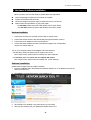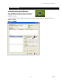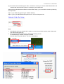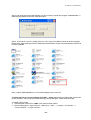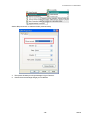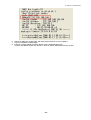
1
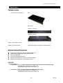
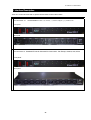
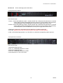
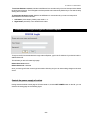
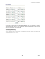
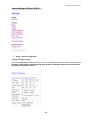
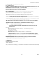
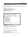
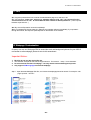
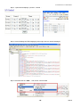
IP POWER 9258-1U USER MANUAL
IP POWER 9258-1U
USER MANUAL
IP POWER 9258-1U USER MANUAL
USER MANUAL
IP POWER 9258-1U
Version: V1.50
2008.05
-1-
VER1.50
IP POWER 1U USER MANUAL
Warning:
Any changes to this equipment without permission may cause damages to your equipment! This equipment
has been proved by CE & FCC to can be prevented from the influence of harmful electronic jamming in normal
business use condition.
IMPORTANT NOTICE
1. We have no responsibility for the possible damage caused by improper usage or abnormal working
environment.
2. Do not use IP POWER in strong shaking condition.
3. Please contact the dealer If IP POWER works improperly.
Copyright © 2005 All rights reserved. No part of this publication may be reproduced, stored in a retrieval
system, or transmitted in any form or by any means, electronic, mechanical, photocopying, recording or
otherwise, without the prior written consent of us
All other products mentioned in this document are trademarks of their respective manufactures.
We are exempt from notify any change of our products.
-2-
IP POWER 9258-1U USER MANUAL
Table of Content
1. INTRODUCTION .......................................................................................................... 4
FEATURES .........................................................................................................................
IP POWER 9258-1U FUNCTION DESCRIBE .........................................................................
2.SPECIFICATION ........................................................................................................... 5
PACKAGE CONTENTS .........................................................................................................
MINIMUM SYSTEM REQUIREMENTS ....................................................................................
3.INTERFACE DESCRIPTION........................................................................................ 6
4.HARDWARE & SOFTWARE INSTALLATION .......................................................... 8
HARDWARE INSTALLATION ..................................................................................................
SOFTWARE INSTALLATION ..................................................................................................
5. INITIAL SETTING......................................................................................................... 9
INITIAL SETTING THROUGH ETHERNET ................................................................................
SETTING OF SOFTWARE SHUT DOWN CONTROLLED PC/ SERVER…………………….
6. HARDWARE CONTROL AND SETTING ...............................................................13
7. CONTROL AND SETTING THROUTH THE INTERNET EXPLORE ....................14
LOGIN ................................................................................................................................
CONTROL THE POWER SUPPLY OF OUTLETS………………………………………………..
POWER SUPPLY STATE QUERY……………………………………………………………...
SYSTEM SETTING ........................................................................................................... …
SETTING THE PASSWORD…………………………………………………………….……
SETTING THE IP ADDRESS.…………………………………………………………………
EMAIL SETTINGS……………………………………………………………………….. …
SETTING THE TIME SCHEDULE……………………………………………………………..
SETUP UP OWN OUTLET DEFAULT STATUS ………………….……………………………
. Internal Clock Settings & Network Time Protocol (NTP)………..……………………..
. WAKE ON LAN………………………………………………………………………………
. GPRS FOR CELL PHONE : SUPPORT WAP……………………………………………….
. FIRMWARE UPDATE: …………………………………………………………………….
8. DDNS SETTING ………………………..…………….………………….……………24
9. CHECK STATUS THROUGH SNMP ……………….………………….……………25
10. CONTROL AND SETTINGS THROUGH HTTP COMMANDS…………...………26
ORDER FORMAT……………………………………………………….…………………….
11. FAQ ……………………………………………………………….…………...............28
12. Webpage Customization ….……………………………….………………………28
-3-
VER1.50
IP POWER 1U USER MANUAL
1. Introduction
The Standard 1U 19” Rack mount, IP POWER 9258-1U is a web controller which can be easily used in the
industry field. With the remote network control technology, user can control or query the power supply of
equipment. User can do this in any computer connected to the internet or local area network, there is no
special program needed, also there is no need to open the external case of the computer.
Try to imagine that while traveling in a foreign country, you can control the power supply of your electric
equipments, such as a computer, a server, a router, an entrance guard or security / surveillance system directly
or use a time schedule comes with the IP POWER 9258-1U. You can remotely control the power switch with
any computer connected to the network, which is not only convenient, but it also big saving on the manpower
and time.
Feature
1. Built in web server, can be used through the Ethernet or Internet network.
2. Support multiple browser, such as Internet Explore, Netscape, you can operate the switch and check the
state without any special program.
3. Control 8 set AC outlet equipment at the same time by standard IEC 320 Outlet connectors.
4. 1U 19” Rack mount Steel case.
5. Supports HTTP, SMTP, ,SNMP, INTERNET- fixed IP, DHCP, LAN - virtual IP
6. Security passwords identify. Easily installed and can be updated online.
7. Supported serial port communication, indicate all kinds of real time state of IP Power 9258-1U.
8. Separated LED indicates the state of each switch.
9. Develop tool (SNMP) is provided. It can be modified to meet the user’s special need.
10. Safely designed for high voltage resistance and protection for leakage of electrical currency, using
nonflammable material
11. Network Server reboot -- can remote control to reboot the power on for the PC or Server at remote site ,
12. Timer Schedule -- can pre-set the time schedule to turn power on / off thru Internet / Ethernet.
13. Support NTP (Network Time Protocol) - synchronize the time of IP Power 9258-1U to the Internet web
address time.
14. WAP Mobile Phone Control - can use the GPRS cell phone via WAP to control
15. Setup up own outlet default: when regain power it store each outlet to those status setting.
16. Provide SDK (VB & VC) for own Software develop and application.
17. Safety shut down controlled PC/ Server ( WINDOWS OS ) by own software
Specification
* Maximum rated voltage of each 4 outlet:
250V AC, 24V DC
* Maximum rated currency of each 4 outlet: 15A AC/DC,
* Maximum rated currency of Individual outlet: 6A AC/DC
* Action delay: Max 10ms
* Working temperature: 0~ 50°C
-4-
IP POWER 9258-1U USER MANUAL
2. Specification
Package contents
One set of IP Power 9258-1U
Front :
Back Panel:
* 9258T-1U Version :
* 9258S-1U Version :
Option : RJ45 (Cat5) net wire
Option : Input Power Cable :
Style Pan European , Australia or United Kingdom
Minimum System Requirements
Intel Pentium III 300MHz or above/compatible AMD CPU
WINDOWS operating system (IE5.0+SPI) & LINUX
Minimum 64MB RAM
VGA Card: supported direct draw
Network card with RJ45 port & Ethernet HUB or Switcher
Network: FIX IP address for Internet power control.
NOTICES:
1. IP Power 9258-1U:
* For 220-250V: please use power (Input) cable at Maximum 10A current for each power input.
Total Max output current for per 4 outlets: 10A.
Individual Max output current for per outlet: 6A.
* For 100-120V: please use power (Input) wire at Maximum 15A current.
Total Max output current for per 4 outlets: 15A.
Individual Max output current for per outlet: 6A.
-5-
VER1.50
IP POWER 1U USER MANUAL
3. Interface Description
There are 2 model of IP Power 9258-1U, please refer the outlook of each model as follow:
Model & outlet style:
IP Power 9258S -1U:
Standard NEMA for: Brazil, 中国, Canada, 日本, Mexico, Philippine, 台灣, Thailand, USA. .
Front panel :
Back panel :
IP Power 9258T-1U: Standard IEC 320 for Universal PC Power outlet - Pan Europe, Oceania, Asia, Africa.
Front panel:
Back panel
-6-
IP POWER 9258-1U USER MANUAL
IP Power 1U : all four series apply same main device.
* Front panel show as below:
From left to the right:
1. Power 1: Power switch (RED) for outlet 1- 4 switch ON /OFF and Self-protect AC reset button to cut off the
power supply of outlets automatically if there is a shortcut or current overload. After user having
solved the problem, push the reset button, the AC power supply will become normal.
2. Power 2: Power switch (RED) for outlet 5- 8 switch ON /OFF and Self-protect AC reset button to cut off the
power supply of outlets automatically if there is a shortcut or current overload. After user having
solved the problem, push the reset button, the AC power supply will become normal.
3. RS232 port: Detect each output state and get IP address to re-update if update fails.
4. On & Off: Hardware power ON /OFF setup. Please do refer page 12 for detail operation
5. LED: 8 LED indicator lights (Outlet 1- 8). If the LED is on, means the corresponding outlet is power on.
* Rear panel shown as below:
From left to the right:
1. 90-240VAC power input port
2. OUT 1- 4: 4 individually switched AC outlets
3. 90-240VAC power input port
4. OUT 5- 5: 4 individually switched AC outlets
5. RJ45 Ethernet port: Link to the net wire.
-7-
VER1.50
IP POWER 1U USER MANUAL
4. Hardware & Software installation
Before you star to use IP Power 9258-1U, please follow the steps below
Check the package to make sure the contents is complete.
Prepare one Ethernet HUB or Router
Check the voltage of the power supply to make sure it is AC 110-240 volt
Please confirm the specification of your power cable.
* For 220-250V, please use power cable at MAX 10A for each 4outlet.
* For 100-120V, please use power cable at MAX 15A for each 4outlet.
Hardware installation
1
Connect the IP Power to a HUB with a RJ45 cable or network cable.
2
Connect the HUB or Router to the internet (May through ADSL/XDSL modem).
3
Connect the power adapter to the IP Power 9258-1U.
4
Connect the power adapters of under control electric equipment to corresponding
out port of IP Power 9258-1U.
Turn on your computer and the power adapter of IP Power 9258-1U
* For 220-250V, please use power wire can support 10A current.
Max. output current: (total of each four outlets) 10A, (each outlet) 6A.
• for 100-120V, please use power wire can support 15A current.
Max. output current: (total of each four outlets) 15A, (each outlet) 6A
Software Installation
Please follow the steps below to install the software.
1. Insert the Installation CD in the package and windows will auto-run. If not please browse for the
Autorun.html file in CD.
.
2. Click IPEdit in the downloads section of the installation CD
3. Save IPEdit to your desktop or any other place of your choosing
4. After you have saved it onto your desktop and double click to run it.
-8-
IP POWER 9258-1U USER MANUAL
5. Initial Settings
Initial setting through the Ethernet
Open “IPEdit.exe”. Make sure that the IP Power 9258-U
is properly turned on and there is a Ethernet connection
from the RJ45 cable.
In the local devices section of IPEdit all products under the same subnet network will appear. Please refer to
(Figure 1.1) below:
(Figure 1.1 IPEDIT)
.
-9-
VER1.50
IP POWER 1U USER MANUAL
(Figure 1.2 IPEdit)
IPEDIT will search and display all IP Products 9XXX series under the same local Ethernet. The default name
for the IP Power 9258-1U is “IP9258” Please refer to (Fig. 1.2 above).
1. Double click and highlight your IP Power 9258-1U device. The default device name and IP/Network settings
will all be displayed on the right hand side of IPEdit.
Make sure that the IP Address of your 9258-1U is setup on the same subnet network as your PC’s
(Subnet mask, Gateway)
*
Represents that your 9258-1U does not match the gateway of your router.
(E.g. If the Default Gateway of your computer is 192.168.1.1 The IP Address of your 9258-1U will need to be
set up to 192.168.1.XXX.)
2a. Automatically Detect Network settings (Please go to 2b. for steps on how to manually enter network
settings)
a.) Click on the REF button to the right of IPEdit
b.) Please wait a few seconds while IPEdit detects your network settings. Then click the Apply button to apply
the new network settings
- 10 -
IP POWER 9258-1U USER MANUAL
2b. Manually enter network settings with Ipedit:
a.) You can manually enter the networks settings for the following:
The name: (please use numbers or letter)
Gateway IP: (The default gateways IP can be found using
IP Address: (please set in the same subnet as your PC) in the text windows.
b.) Then click Submit after the settings have been selected. Wait about 20 seconds for the new settings to be
updated.
c.) Click Rescan, and the new device settings will display in text window.
Note:
1.) Make sure the RJ45 network cable is connected and the 9258-1U is powered on.
2.) * The default IP address of the 9258-1U is 192.168.10.100. If you cannot get into the webpage of the
9258-1U, please make sure to set subnet of the IP Power 9258-1U to match with your PC Subnet Mask.
To obtain the IP information manually:
In Windows Go to:
a.) Start Run type in “cmd”
b.) Now type in “ipconfig”
Hit enter and the MS –DOS window will open,
The last set of numbers of the IP address can be any number between 1~254, but cannot be same as your PC,
hub, router or any device in the network. If using in any PC, just use HUB and type the 192.168.0.100 in
Browser or use “IPDdit.exe “ then you can get in the web page.
* Same SUBNET: The first 3 sections of IP address is same - XXX.XXX.XXX.abc. The part of XXX must be
the same.
(E.g. IP address is 192.168.1.100, then another IP address 192.168.1.123 is the IP in same subnet.)
5 .The default username and password of IP Power 9258 are:
Username: admin
Password: 12345678
- 11 -
VER1.50
IP POWER 1U USER MANUAL
Setting of software shut down controlled PC/ Server
9258 can be used to safely turn off the PC/Server through Network. With this feature you can remotely
shutdown any PC/ Server which that is connected to the IP Power 9258 through normal Windows shut down
procedure. Before operating the software shutdown function it is essential to install our software:
1. Please install program “IP9258service.exe “ into the PC that will be controlled.
2. Documents created in programs like Microsoft office will not be automatically saved. The 9258 will still
shutdown the controlled PC/server without saving the file.
3. You will need to reserve enough time for controlled PC/Server to shutdown after receiving a command from
the 9258. Please set the delay time at 30 or 60 second in 9258 configuration webpage (setup delay
switch).
4. The controlled PC/Server must be in the same ETHERNET and the same SUBNET as the 9258..
Installing and Setup of the “IP9258service.exe”:
1. Insert the CD that came with the device into the PC that you want to be able to turn off.
2. Click on the
icon
Icon.
3. On the left hand side click on the
4. Go to the 9258 Series section and click on the Link that says Shutdown Program
5. Save to your desktop and double click “ IP9258config.exe” ,to install the program:
- 12 -
IP POWER 9258-1U USER MANUAL
6. Please fill correct information in each section :
* IP9258 Address: Please type in the IP address of the 9258.
* HttpPort: Fill the port of 9258, default value is 80, if amend the port in 9258 please correct.
* UserName: admin
* Password: 12345678 (password can amend in web page)
* Power Number: Please enter the power number in the 9258 that you want to control (If many PC/Server use
same power extended line, the extended line connect to channel 1 of 9258 and if all the PC /
Server set as channel 1 and same IP address in IP9258service.exe , then all the PC/Server
will be controlled at same time).
a.) Click on “Save Change “.
b.) Then Click “Install Service”
c.) Then “Start Service” then please shutdown the PC/Server.
After the PC has been restarted, the function will be in effect.
6. Hardware control & setting
* This function teaches you how to use the hardware control the power on/off of the devices
NOTE:
This function is solely used for manually selecting which ports you need to be on or off. It was designed so that
you can still have the ability to turn on or off certain ports in the case you do not have Ethernet connection.
Before using the H/W control function, please UNPLUG all the 4 connection or ports connected to the
9258.
Control panel as follow:
- 13 -
VER1.50
IP POWER 1U USER MANUAL
To activate Hardware control: Hold the On/Off Button for 5 seconds until you hear one beep which activates
the H/W Control function. The LED lights in the front panel should continuously flash and you can hear the relay
clicking when activated.
To deactivate Hardware control: Hold the On/Off Button for 5 seconds until you hear one beep which
deactivates the H/W Control function.
1. Left Button (Circle button): Select power outlet 1 ~4.
2. Right Button (ON/ OFF): Turn ON/OFF each outlet.
7. Control and settings through the Internet Explore
To login to the IP Power 9258 device through Internet Explorer, type in the IP Address of your device into the
address field of IE.
This will take you to the IP 9258 Login page.
Default User Name: admin
Default Password: 12345678
Once you have typed in the correct login information click okay and you can start making changes to the web
server.
Control the power supply of outlets
Having entered the Web Control page of IP Power 9258-1U, click the SET POWER button on the left, you can
enter the IO setting page as the following figure:
- 14 -
IP POWER 9258-1U USER MANUAL
IP Power 9258-1U can control 8 outputs individually at the same time. User can choose power on or power off
with an electrical outlet . User may fill in the corresponding columns with the delay time you wish in seconds,
then choose the action after delay to be on or off.
Power Supply State Query
Click the “Set Power” button on the left column, and the page will be refreshed. The state of each electric outlet
will also be displayed in column control.
- 15 -
VER1.50
IP POWER 1U USER MANUAL
System Settings of IP Power 9258-1U
1.) Setup – System Configuration
System configuration page:
Click on the Setup link located on the left hand column. In this page the user will be able to manually enter the
IP Address, Subnet Mask, Default Gateway, DNS:, DHCP Client, Beeper, Http Command Verification,
Delay Switch, and Release Version
- 16 -
IP POWER 9258-1U USER MANUAL
IP address Settings: Ethernet (LAN) and Internet(WAN)
Local Area Network (LAN) :
In LAN, you can set a fixed IP address or gain it from a DHCP server automatically. We recommend you use a
fixed IP address so you can access the 9258-1U through the internet.
Now type the new IP address in the address field of IE, you can visit the 9258-1U. You also can use the
ipedit.exe to find the IP Power 9258-1U and modify its IP address.
Work on Internet (WAN):
User can set the IP provided by your ISP. If the IP Power 9258-1U has a public IP address,
you can control it through the Internet. IP Sensor 9258-1U supports fixed IP, DHCP.
* IP Address: Please type in the IP address provided by your ISP. If IP Power 9258-1U.
* Subnet Mask: please type in the Subnet Mask provided by your ISP. If IP Power 9258-1U is working with a
Router, please refer to the network settings of the Router.
* Default gateway: please type in the Default Gateway provided by your ISP. If IP Power 9258-1U is working
with a Router, please refer to the network settings of the Router.
*DNS Server: please fill in the IP address of DNS server. If you are in Taiwan, you can set it to 168.95.1.1.
*DHCP Clients: Enable– activate DHCP service. DHCP will assign IP address for each PC.
Disable – shut down the DHCP service. You can set the IP address by yourself.
*Beeper:
Enable – activate the sound beeper .
Disable – turn off the sound beeper.
If you control the 9258-1U through the web page, the beeper will beep once when the
operation works.
Reminder:
*IP address format: XXX.XXX.XXX.XXX:YYYY YYYY means the port number,
(I.E 192.168.1.100:2345)
Port ranges from: 1 to 32767
.
*Subnet Mask: Ranges from 0 to 254 (xxx.xxx.xxx.0 ~ xxx.xxx.xxx.254 )
*If DHCP is disabled, then the user must set the TCP Port and default Gateway .If DHCP is
enabled, then the TCP port will be preset to 80( xxx.xxx.xxx.xxx:80 ) and the default gateway will
be set by the DHCP server.
Http Command Verification: Setup the control possibility from HTTP command or SDK (VB & VC)
1. Select Cookie+Base64: To enable HTTP command & SDK control
2. Select Cookie: To disable HTTP command & SDK control
2.) DDNS Settings
Please refer to page 23 for more details
3. EMAIL SETTINGS:
When you finished the e-mail settings, you can set to let IP Power 9258-1U send its IP address automatically.
- 17 -
VER1.50
IP POWER 1U USER MANUAL
For example:
* Mail Server: smtp.sample.com
* Port:
25
* Pop3Server: pop3.sample.com
* Password: ***********
* Sender: [email protected]
* Receiver 1: [email protected]
* Receiver 2: [email protected]
* Receiver 3: [email protected]
* Subject: This is the subject line
* MailBody: This is the body of the email
1.) Mail Server: Outgoing Mail Server
Please make sure the server is an available mail server.
2.) Pop3Server: Incoming Mail Server. IP address ( in Internet WAN ) from your ISP for sending Internet
IP address by E-mail when 9258 in Internet. To receive IP address in WAN , please fill your ISP
e-mail receive server. In this part, please also set the DNS of your ISP in system
configuration.
3.) Password: the password of this mailbox is no longer than 8 characters.
4.) Sender: please fill in the name of sender. The Mail Server must support SMTP and these fields must
be filled in correctly.
5.) Receiver:no longer than 50 English letters. Please use blank space to separate two
receiver’s e-mail address. After you have finished this setting, you will receive the email to inform
you the IP address of the IP Power 9258 every time you enter the webpage.
6) Subject: the subject of the mail to be no more than 50 English letters.
- 18 -
IP POWER 9258-1U USER MANUAL
7) Mail Body: please type the content of the mail here, it cannot be left empty.
After you have finished all of the above settings, click “SAVE“ and your settings will be saved.
4.) Setting the password for IP Power 9258:
Click the “Change password “ button on the left you can enter the change password page. The default
password of 9258 is 12345678.
User can change it into any password (not longer than 8 bit), then click apply button to save the change.
Note : If forget the password , Use username " super user " when log in webpage and then click "OK
" turn power off for few second and then turn ON power . 9258 will to set back to default
password. ( There is space between super and user. )
5.) Control the IP Power 9258 through Power Schedule:
With the power schedule the user can use this section to schedule daily events to control the devices attached
to the 9258
If user wishes to control the power in one outlet of IP Power 9258, you can fill in the time in the ower control
column and choose on or off.
- 19 -
VER1.50
IP POWER 1U USER MANUAL
4-2: Click “power schedule 2” to control outlet 5-8 .
Support parameter of operate schedule:
Disable
Just Once
Every day
Work Day: From Monday to Friday.
Weekend: Saturdays and Sundays
Setup up own outlet default status:
When power, each outlet will set as appointed default status
6.) Wake on LAN (WOL):
Remote Wake up PC by MAC address in Ethernet (LAN)
Use Network port (RJ45), you can wake PC on WAN by PC `s MAC address.
Wake On LAN (WOL) premise:
(1) First the main board needs to have Wake on Lan support. There must be a port to connect to your network
card. If the motherboard supports WOL ,will need to enable this function in the BIOS setting.
- 20 -
IP POWER 9258-1U USER MANUAL
(2) Your network card must also support “WOL”, remember to connect your connect cable to Main board or the
network card cannot send the “power on” message to your motherboard.
After both the motherboard and network card have been setup, you can use WOL function by following
the steps below:
Step 1: Log in 9258 web page and go to “Network Wakeup”
Step 2: Type in your MAC address then press “send” – the PC will be power ON.
Note:
1. If the Network card is not onboard card, it needs to connect with your Main board by cable. Please refer
your network card connection
2. You can get your MAC address in PC , please refer following pictures :
Go to Network sign Status Support Details
Then the value in Physical Address “ is the PC` MAC address.
- 21 -
VER1.50
IP POWER 1U USER MANUAL
7.) Internal Clock Settings & Network Time Protocol (NTP):
* User can enter the internal clock settings : year , month, day , hour , minutes and second.
* NTP function : customer can synchronize the time of IP Power 9258-1U to the Internet web address time .
Please refer following the NTP server IP address :
* 131.246.9.116
* 139.18.25.34
* 128.176.191.9
Note: To work NTP, please do set up in e-mail and have to receive e-mail from IP Power 9258-1U.
IP Service
IP Server gives the user the ability to easily search for the name of the device other than searching for a long IP
number. This flexibility allows the user to easily just remember the name of their device so they can access it
with ease.
To Enable IP Server:
Go to IPSrv Conf on the Left hand side of the Webpage and then make sure you have IPSrv On/Off on On.
The default IP server IP Address is 220.135.169.136 and provided.
The user can also setup his/her own IP Server system and use their own address as well.
- 22 -
IP POWER 9258-1U USER MANUAL
By setting the server address in IP server of advanced setup page, the user can easily search for his/her IP
Power 9258-1U on internet just by searching for the name of the device. The default IP address of IP server
is 220.135.169.136.
Step1: Click the green “connect” button
Step2: In the device name section: Type in the name of your device (Min of 3 letters)
8.) Firmware update:
If no firmware to update please do not go to this page.
When there a new firmware to update, the user will get additional functions that is created for the IP Power
9258. Click the firmware update on the right side of the page; and wait for a new window to pop up.
Step1: Click the“firmware update“,you will see follow webpage :
Note: Do not click “ update “ if there is no firmware file to update .
Step2 : Click update button, the following window will pop up.
Step 3: Click the Brower button to find the corresponding update file (you can download it from our web site or
ask it from the dealer), then click Update button to start update firmware. When the update is finished, you must
wait one minute before you restart the IP Power 9258.
NOTICE:
* Before running the online update program, please make sure that the TCP port is set to 80,or the
online update may fail.
* Please check with your reseller /distributor / importer for the update news.
* If the update fail please refer chapter 10 “ Webpage Customization“
- 23 -
VER1.50
IP POWER 1U USER MANUAL
8. DDNS SETTING
When the user connects to the Internet through ADSL (PPPOE Service), the IP address that you receive from
ISP is usually a dynamic IP Address. Therefore when someone wants to visit your device they are usually not
able to because the IP Address is dynamic and it will keep changing. By using DDNS this problem is solved.
Below we will explain using the DDNS service provided by www.dyndns.com:
1.) First, apply for a domain name (Ex. [email protected]) in www.dyndns.com for the 9280.
2.) Set the domain password and select the proper DNS server (for example, dnsdojo.net) for domain name
resolve.
1.) Then input the Domain Name Server (host name), user name, password, and, etc in the DDNS webpage
of 9280.
2.) After you have set every up correctly every time the 9280 start or user selects submit, the 9280 will send a
message package including its current IP address, domain name to www.dyndns.com, then the DNS
server you choose will link the domain name of 9280 to its current IP address. That way the visitor can visit
the 9280 webpage by inputting the domain name of 9280 (abcdefg.dnsdojo.net) in the address column of
the browser.
DDNS Server IP: Type in the IP Address and port number provided by www.dyndns.com Please refer to the
figure above for reference.
Your Domain: Please type in the domain name that you have chosen to use.
DDNS UserName: Enter your DDNS User Name here
DDNS Password: Enter your DDNS password here
Enable DDNS: This setting allows you to enable DDNS or disable. Select True – If you want to enable DDNS
and Select False – If you want to disable DDNS
- 24 -
IP POWER 9258-1U USER MANUAL
Proxy Enable: If you need to use a proxy Server, Select True – to enable proxy and Select False – to disable
proxy.
PROXY IP: If proxy is enabled you will need to enter the Proxy Servers IP Address
PROXY PORT: If proxy is enabled enter the port of your proxy server IP Address here
Note: Once you are done setting up these configuration settings make sure you hit the Save Button
and then the Update Now to confirm completion
9. Check status though SNMP
IP Power 9258-1U support SNMP V1 and V2 , user can use snmp program to get the status of each port in IP
Power 9258-1U.
- 25 -
VER1.50
IP POWER 1U USER MANUAL
10. Control and Settings Through HTTP Commands
User can control the 9258’s action directly though the HTTP orders.
The format of the HTTP order is:
http://username:[email protected]/Set.cmd?CMD=Commnand+para1=*+para2=*+para3=
*……
Explanations for the command syntax:
Username: 9258’s username, default username is admin
Password: 9258’s password, default password is 12345678
XXX.XXX.XXX.XXX the IP Address of 9258
CMD=***Power : the function module of 9258
para1 ~ para3 parameters
Example 1: Control the power supply of 9258 using SetPower:
http://admin:[email protected]/Set.cmd?CMD=SetPower+
P60=1+P61=1+P62=1+P63=0+P64=1+P65=1+P66=1+P67=0
This command control IP Power 9258 IP address at 192.168.1.0, user name is
admin and password is 12345678.
This command will:
P60 (Outlet1) = Power On
P61 (Outlet2) = Power On
P62 (Outlet3) = Power On
P63 (Outlet4) = Power Off
P63 (Outlet5) = Power On
P63 (Outlet6) = Power On
P63 (Outlet7) = Power On
P63 (Outlet8) = Power Off
*
When this order is sent, the IP Power will return the following message:
<html>P60=1,P61=1,P62=1,P63=0</html>
Function of 9258:
1. SetPower: To control I/O - read parameter as follow
http://admin:[email protected]/Set.cmd?CMD=GetPower
out2-out4 same as out1
2. GetPower: Reads output 1-4 to see if the status of each output
http://admin:[email protected]/Set.cmd?CMD=GetPower
Explanation for the command SetPower:
IP address (XXX.XXX.XXX.XXX): 192.168.1.10 (IP Address of the device)
Username: admin (Username of the device)
- 26 -
IP POWER 9258-1U USER MANUAL
Password: 12345678 (Password of the device)
When you use this command, 9258 you will get the following message output :
<html>P60=1,P61=1,P62=1,P63=0 , P64=1,P65=1,P66=1,P67=0</html>
* Schedule Control: User can use HTTP command to arrange the 9258 operation in specific time ,http
command format as follow:
http://username:[email protected]/Set.cmd?
CMD=SetSchedule+Power=**+YY=****+MM=**+DD=**+HH=**+MN=**+SS=**+PARAM=****+ONOFF=*
Explanations of each part of the order for the command SetSchedulePower:
IP Address (XXX.XXX.XXX.XXX): 192.168.1.10 (IP Address of the device)
Username: admin (Username of the device)
Password: 12345678 (Password of the device)
Control parameter are 1A 1B 2A 2B 3A 3B 4A 4B .
A means connect power . B means discount power
YY=****+MM=**+DD=**+HH=**+MN=**+SS=*
YY : year ( 20YY ) , 01 = 2001
MM : month ( 0 1-12 )
DD : date ( 01-31)
HH : hour (24 hours : 0- 23)
MN : minute ( 1-60 )
SS : second (1-60)
: time parameter
PARAM=* : time schedule parameter . Parameter list as follow:
128
127
31
96
operate ONCE
EVERYDAY
MONDAY to FRIDAY
SATURDAY & SUNDAY
ONOFF=* : operate parameter
0 open
1 close
Example 1: control power on / off of 9258:
http:// /admin:[email protected]/Set.cmd?
CMD=SetSchedule+Power=1A+YY=2006+MM=02+DD=16+HH=06+MN=02+SS=16+PARAM=128+ONO
FF=1
Above command control one IP Power 9258 IP address at 192.168.1.0, user name is admin and password is
12345678. This 9258 will connect power of outlet1 (p60) on
2006/2/16 06:02
Note:
1. Please use + to separate each parameter ,you can only control certain power on /off as :
http://admin:[email protected]/ Set.cmd?CMD=SetPower+P60=1
2. Please follow the capital and lower case in command format.
- 27 -
VER1.50
IP POWER 1U USER MANUAL
11. FAQ
Q1: I forgot the password and can not enter the administration page now, what can I do?
A1: Use username "super user" when log in webpage and then click "OK " turn power off for few
second and then turn on ON . IP Power 9258-1U will to set back to default password. ( There is space
between super and user. )
Q2: Why the on/off operation can work immediately?
A2: if you operate theIP Power 9258-1U in Ethernet, the operation will work immediately. If you operate it
through the Internet, the response speed depends on the situation of the network.
12. Webpage Customization
Customer can use our Web page SDK to amend the word and background pictures for your 9258. If
not familiar to write webpage, please do not do this amendment.
Important Notice:
1.
1.
2.
3.
Each file do not over the original file size.
The character word part do not over the original amount . For instance : “setup “ it is 5 characters.
Do not amend the structure of webpage – can only amend words and background picture.
Only support HTML langrage to amend the webpage.
Step 1 : Open the 9258 Webpage SDK file , and choose the webpage planned to amend. For example : web
page “ipcontrol “ html file ”
- 28 -
IP POWER 9258-1U USER MANUAL
Step 2 : Open amend webpage “ipcontrol “ html file :
Step 3. Amend webpage by HTML langrage( get from right click as in amend webpage”):
Step 4 :Save file format as “UNIX” : Like choose “DOS to UNIX
- 29 -
VER1.50
IP POWER 1U USER MANUAL
Step 5. After amend the other 9258 webpage you plan to amend . Please open program “Make9258Html “ in
9258 web page SDK and just press” make html patch”.
Step 6 . There will be a new file “ Update_2006-01-11.bin” which is the BIN file include the amend webpage.
Please follow 9258 update procedure to update the firmware BIN file . Please note the Update procedure must
be done in port 80.
Note: program “Make9258Html.exe “ and amend webpage must in same file.
* If update fail and can not get IP address by IP EDIT , please use RS232 jack ( DB 9 Cable) connect with
the PC and 9258, and you can get IP address to log-in and update again. Please refer follow step:
1.POWER OFF the 9258
2. Use DB9 cable connect to the COM1 of PC and the RS232 of 9258
3. Execute WIN program " Hyper Terminal" : please go to " Start" --> " program" " Accessories " -->
" Communications " “Hyper Terminal” .
- 30 -
IP POWER 9258-1U USER MANUAL
Set the “Bits per second” as 19200 at COM1 ( Must at COM1)
4. Then power ON 9258 you will get message in Hyper Terminal .
5. Please check the message and get your IP address.
- 31 -
VER1.50
IP POWER 1U USER MANUAL
6. Use this IP address to update again. We supply original firmware V1.22 for update f
7. Log tin this address to update again.
8. If still can not finish update successful, please check if create BIN file too big .
If need to ship BIN file, please use bin file V1.22.bin in SDK to update back to factory version.
- 32 -