1
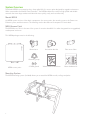
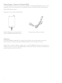
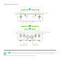
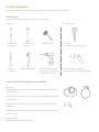
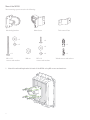
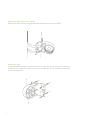
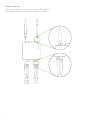
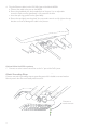
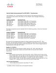
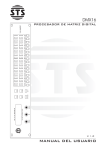
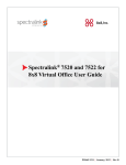
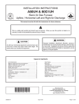
Meraki MR58
Hardware Setup Guide
Trademarks
Meraki, Meraki MR58, Meraki Cloud Controller, and Meraki Mesh are trademarks of Meraki, Inc.
Other brand and product names are registered trademarks or trademarks of their respective holders.
Statement of Conditions
In the interest of improving internal design, operational function, and/or reliability, Meraki reserves the right
to make changes to the products described in this document without notice. Meraki does not assume any
liability that may occur due to the use or application of the product(s) or circult layout(s) described herein.
Warranty
Meraki, Inc. provides a limited warranty on this product. Warranty details may be found at www.meraki.com/legal.
1
Contents
· System Overview
· Understanding the MR58
· Pre-Site Preparation
· On-Site Instructions
· Troubleshooting
· Regulatory Information
2
3
5
8
8
18
19
System Overview
The Meraki MR58 is an enterprise-class, three radio, 802.11n access point designed for rugged environments.
When connected to the Meraki Cloud Controller , the MR58 enables the creation of high-speed and reliable
networks that cover large outdoor and industrial areas quickly, easily and cost-effectively.
TM
Meraki MR58
An MR58 system consists of four basic components: the access point, the mounting system, the Power over
Ethernet system, and the antennas. The following section describes each component in more detail.
MR58 Access Point
The MR58 Access Point is the core of the system. It contains three 802.11n radios integrated into a ruggedized,
weatherproof enclosure.
This MR58 package contains the following:
Mount base
Articulation bracket
Pole mount V-bar
Wood screws and anchors
Mount hardware kit
Grounding strap
MR58 access point
2 Cable glands
Mounting System
The MR58 mounting system (included) allows you to attach the MR58 to walls, ceilings and poles.
3
Power System - Power over Ethernet (PoE)
The Meraki MR58 accepts Power over Ethernet (802.3af); the Meraki PoE 802.3af injector is sold
separately. Instructions contained in this setup guide assume your MR58 will be powered by the
Meraki PoE 802.3af injector.
The power system contains the following:
802.3af PoE power source (either PoE
switch or Meraki 802.3af PoE Injector)
Country-specific AC power cable
Antennas
The Meraki MR58 has three 802.11n radios. Each radio has two external antenna connectors;
both connectors for a particular radio should be attached to the same type of antenna.
Meraki offers a number of different antennas for use with the MR58. Alternately, you may purchase
3rd party antennas for use with the MR58. Make sure they have N-type connectors and support the
proper frequency band (2.4 or 5GHz).
4
Understanding the MR58
Your Meraki MR58 has the following features:
LED indicators
Accessory antenna attachment holes
Mount attachment holes
Accessory antenna attachment holes
Grounding posts
Vent
Vent
The vent allows pressure and humidity equalization between the interior and the enviroment. This prevents
internal condensation and maintains a water proof seal.
Grounding Post
Provides an attachment point on the Access Point for the grounding strap (included). This post is threaded
to accept a M4 x 0.7mm bolt
5
Understanding the LED Indicators
Your MR58 is equipped with a series of LED lights on the front of the unit to convey
information about system functionality and performance.
Signal Strength
One Light: Fair
Four Lights: Strongest
Moving Lights: Searching for signal
Flashing Lights: Error state. May indicate bad gateway or other routing fault
Ethernet
Off: No active network connection on either ethernet port
On: An active network connection is connected to either Eth0 or Eth1
Flashing: Error state. May indicate bad gateway or other routing fault
Radio Power
Off: MR58 is off
On – Orange: MR58 is booting or trying to find a path to the internet
On – Green: MR58 is fully operational and connected to the network
Flashing – Orange: Firmware is upgrading
Flashing – Green: Error state. May indicate bad gateway or other routing fault
6
Understanding the Ports
TOP
BOTTOM
ETH0+PoE
Primary ethernet
and power port
ETH1
Secondary
ethernet port
and
are 5GHz radios for mesh or client communication. Each radio has two external N-type connectors.
is a 2.4GHz radio primarily used for client communication. However, it can also communicate with Meraki
2.4Ghz access points. This radio has two external N-type connectors.
7
Pre-Site Preparation
You should complete the following steps before going on-site to perform the installation.
Collect Tools
You will need the following tools to perform your installation:
Required
Recommended
x2
Straight-slot
screwdriver
Phillips
screwdriver
9/16”(13mm)
wrenches
Adjustable wrench
Rubber mallet
Drill with appropriate bits
for mounting wall anchors
(if mounting to a wall)
Collect Additional Hardware for Installation
Required
Network cables with RJ45 connectors long enough for your particular
mounting location
Connection to the internet (if you are setting up your MR58 as a gateway
to the internet)
Appropriately sized metal straps (if mounting to a pole larger than 3.0”
in diameter)
Specialized mounting hardware if mounting to surface other than wood,
stucco or stone
Recommended
Laptop with wireless to verify setup
8
Tin snips
(if mounting with hose clamps)
Power screwdriver with 5/16”
(8 mm) nut driver, Phillips & flat heads
Configure Your Network in Dashboard
We recommend that you add your MR58 to a network in Dashboard before mounting it in the field.
1. 2. 3. 4. * Login to http//dashboard.meraki.com. If this is your first time, create a new account.
Find the network to which you plan to add your nodes.
Add your nodes to your network. You will need your Meraki order number (found on your invoice) or
the serial number of each node, which looks like Q2xx-xxxx-xxxx, and is found on the bottom of the unit.
Finally, go to the map view and place each node on the map by clicking and dragging it to the location where you plan to mount it. You can always modify the location later.
If you do choose to add the node to Dashboard after the installation, make sure to write down the
serial number and MAC address of the unit before installing.
On-Site Instructions
Find a Good Mounting Location
A good mounting location is important to getting the best performance out of your MR58 Access Point.
Keep the following in mind:
1. 2. 3. 9
The Power over Ethernet System supports a maximum cable length of 100m. The Power over Ethernet Adapter and Injector are not rated for outdoor use, and must be installed indoors or in a weatherproof outdoor-rated enclosure.
The Meraki MR58 should have line of sight to as many other Meraki devices as possible. If being installed as a repeater, special care should be taken to optimize the view in the direction of the
closest known gateway.
The antennas should be as unobstructed as possible. Make sure that there is clearance around the MR58 for installation of all of your chosen antennas.
Mount the MR58
Your mounting system contains the following:
Articulating bracket
Mount base
x3
Pole mount V-bar
x4
x3
x2
x4
x4
x3
M8 x 110
screws and washers
M8 nut
M5 x 12
screws and washers
x2
Wood screws and anchors
1. Attach the articulating bracket to back of the MR58 using M5 screws and washers.
10
2. Attach mount base to mounting structure (pole, wall or ceiling). Before tightening fasteners, make sure that the MR58 will be pointing in the correct direction after mounting.
Mounting for poles less than 1.5” (35mm)
Attach mount base and V-bar to pole as shown using M8 bolts and washer.
Mounting for poles less than 3” (80mm) and larger than 1.5” (35mm)
Attach mount base and V-bar to pole as shown using M8 bolts and washers.
11
Mounting for poles larger that 3” (80mm)
Attach mount base to pole using appropriately-sized metal straps (not included).
Mounting on walls
Using appropriate wall anchors and screws for the surface you are mounting to (if mounting to
wood, stucco or stone, use anchors and screws included with mount), attach the mount base
to your mounting wall.
12
Remaining mounting steps are illustrated assuming the MR58 is mounted to a pole
between 1.5 - 3” in diameter; however, instructions are the same regardless of what
the access point is mounted to.
3. Attach the articulating bracket to the mount base using a M8x110 bolt, nut and washers. Do not over-tighten the central bolt because the articulating bracket and mount base
are hard to separate after they are firmly assembled together.
Omni antennas perform best in a mesh network when oriented vertically.
13
Attach Antennas
Remove protective plastic covers from all six N-type RF connectors.
Attach appropriate antennas (and protective boots if included).
14
Power the MR58
Connect PoE Injector to Power and Ethernet
1. Plug the power cord into the PoE Injector and the other end into wall power in a weather-protected location. The PoE Injector is NOT weather-resistant and must be
protected from moisture.
2. Plug an Ethernet cable that is connected to an active Ethernet connection into the “IN“ port on the injector.
3. Connect Ethernet cable that will be routed to the MR58 to the “OUT“ port on the injector.
For more details, see Meraki
802.3af Power Over Ethernet
Injector datasheet.
PoE
3
PoE
2
15
LAN
LAN
DC
1
Attach Power over Ethernet to MR58
1. Remove the dust cover from the PoE+Eth0 port of the MR58. Unscrew it with a coin or flathead screwdriver.
2. Route the Ethernet cable from the PoE Injector “Out” port to the MR58.
3. Install a Cable Gland on the MR58 end of the cable.
16
4.
Plug the Ethernet cable into the PoE+Eth0 port of the Meraki MR58.
a. Connect the cable to the port on the MR58.
b. Screw the gland body into the threaded hole of the port. Use an adjustable
wrench to make sure the gland body is fully seated in the hole.
c. Insert the split ring gasket into the gland body.
d. Screw the cap tightly onto the gland. You may need a wrench to fully tighten the cap,
but take care not to damage the cable in the process.
Optional: Make the MR58 a gateway
1. Connect an active internet connection to the “In” port of the PoE injector.
Attach Grounding Strap
Connect one end of grounding strap to grounding post with included screw and washer.
Security attach the other end nearby metal structure.
Connect to
metal structure
17
Aim Antennas
If you are using directional antennas, aim them appropriately to ensure optimal performance for your
specific network topography.
Test Your Network
Confirm that you have good signal strength throughout your coverage area. You can use the signal
strength meter on a laptop.
Troubleshooting
See the Meraki knowledge base at http://meraki.com/help/kb for additional information and
troubleshooting tips.
18
Regulatory Information
U.S. Regulatory Wireless Notice
Federal Communication Commission Interference Statement:
This equipment has been tested and found to comply with the limits for a Class B digital device, pursuant
to Part 15 of the FCC Rules. These limits are designed to provide reasonable protection against harmful
interference in a residential installation. This equipment generates, uses and can radiate radio frequency
energy and, if not installed and used in accordance with the instructions, may cause harmful interference
to radio communications. However, there is no guarantee that interference will not occur in a particular
installation. If this equipment does cause harmful interference to radio or television reception, which can
be determined by turning the equipment off and on, the user is encouraged to try to correct the interference
by one of the following measures:
•
•
•
•
Reorient or relocate the receiving antenna.
Increase the separation between the equipment and receiver.
Connect the equipment into an outlet on a circuit different from that to which the receiver is connected.
Consult the dealer or an experienced radio/TV technician for help.
FCC Caution:
Any changes or modifications not expressly approved by the party responsible for compliance could void
the user’s authority to operate this equipment.
This device complies with Part 15 of the FCC Rules. Operation is subject to the following two conditions:
• this device may not cause harmful interference, and
• this device must accept any interference received, including interference that may cause undesired operation.
FCC Radiation Exposure Statement:
This equipment complies with FCC radiation exposure limits set forth for an uncontrolled environment. This
equipment should be installed and operated with minimum distance 46 cm between the radiator and your
body. This transmitter must not be co-located or operating in conjunction with any other antenna or transmitter.
IEEE 802.11b or 802.11g operation of this product in the USA is firmware-limited to channels 1 through 11.
19
Canadian Regulatory Wireless Notice
This device complies with RSS-210 of the Industry Canada Rules. Operation is subject to the
following two conditions:
• this device may not cause interference and
• this device must accept any interference, including interference that may cause undesired
operation of the device.
IC Radiation Exposure Statement:
This equipment complies with IC radiation exposure limits set forth for an uncontrolled environment.
This equipment should be installed and operated with minimum distance 20 cm between the radiator
and your body.
This device is intended only for OEM integrators under the following conditions:
• the antenna must be installed such that 46 cm is maintained between the antenna and users, and
• the transmitter module may not be co-located with any other transmitter or antenna,
• for all products market in US/IC, OEM has to limit the operation channels in CH1 to CH11 for
2,4G band by supplied firmware programming tool. OEM shall not supply any tool or info to the
end-user regarding to Regulatory Domain change.
As long as 3 conditions above are met, further transmitter test will not be required. However, the
OEM integrator is still responsible for testing their end-product for any additional compliance
requirements required with this module installed (for example, digital device emissions, PC
peripheral requirements, etc.).
Important Note:
In the event that these conditions can not be met (for example certain laptop configureations or
co-location with another transmitter), then the FCC/IC authorization is no longer considered valid
and the FCC/IC ID can not be used on the final product. In these circumstances, the OEM
integrator will be responsible for re-evaluating the end product (including the transmitter) and
obtaining a separate FCC/IC authorization.
End Product Labeling:
This transmitter module is authorized only for use in device where the antenna may be installed such
that 46 cm may be maintained between the antenna and users. The final end product must be labeled
in a visible area with the following: “Contains FCC ID: UDX-62009015, IC: 6961A-62009015
Manual Information To the End User:
The OEM inegrator has to be aware not to provide information to the end use regarding how to install
or remove this RF module in the user’s manual of the end product which integrates this module. The
end user manual shall include all required regulatory information/warning as show in this manual.
Europe – EU Declaration of Conformity
This device complies with the essential requirements of the R&TTE Directive 1999/5/EC.
The following test methods have been applied in order to prove presumption of conformity with the
essential requirements of the R&TTE Directive 1999/5/EC:
Radio:
EN 300 328, EN 300 893, EN 302 502
EMC: EN 301 489-1, EN 301 489-17
Safety: EN 60950
RF Exposure: EN 50392
Emissions: EN 55022, EN 61000-3-2, EN 61000-3-3
Immunity: EN 61000-3-2, EN 61000-3-3, EN 61000-4-2,
EN 61000-4-3, EN 61000-4-4, EN 61000-4-5,
EN 61000-4-6, EN 61000-4-11
This device is a 2.4 GHz and 5 GHz wideband transmission system (transceiver), intended for use in all
EU member states and EFTA countries with the following restrictions:
In Italy the end-user should apply for a license at the national spectrum authorities in order to obtain
authorization to use the device for setting up outdoor radio links and/or for supplying public access
to telecommunications and/or network services.
This device may not be used for setting up outdoor radio links in France and in some areas the RF output
power may be limited to 10 mW EIRP in the frequency range of 2454 - 2483 MHz. For detailed information
the end-user should contact the national spectrum authority in France.
The device may not be used in the 5 GHz spectrum unless the 5.725 - 5.875 GHz and has been disabled.
This can be done through the Meraki Dashboard.
21
Česky (Czech)
Meraki, Inc. tímto prohlašuje, že tento wireless device je ve shodě se základními
požadavky a dalšími příslušnými ustanoveními směrnice.
Dansk (Danish)
Undertegnede Meraki, Inc. erklærer herved, at følgende udstyr wireless device
overholder de væsentlige krav og øvrige relevante krav i direktiv 1999/5/EF.
Deutsch (German)
Hiermit erklärt Meraki, Inc., dass sich das Gerät wireless device in Übereinstimmung
mit den grundlegenden Anforderungen und den übrigen einschlägigen Bestimmungen
der Richtlinie 1999/5/EG befindet.
Eesti (Estonian)
Käesolevaga kinnitab Meraki, Inc. seadme wireless device vastavust direktiivi 1999/5/
EÜ põhinõuetele ja nimetatud direktiivist tulenevatele.
English
Hereby, Meraki, Inc., declares that this wireless device is in compliance with the
essential requirements and other relevant provisions of Directive 1999/5/EC.
Español (Spanish)
Por medio de la presente Meraki, Inc. declara que el wireless device cumple con los
requisitos esenciales y cualesquiera otras disposiciones aplicables o exigibles de la
Directiva 1999/5/CE.
Ελληνική (Greek)
ΜΕ ΤΗΝ ΠΑΡΟΥΣΑ Meraki, Inc. ΔΗΛΩΝΕΙ ΟΤΙ wireless device ΣΥΜΜΟΡΦΩΝΕΤΑΙ ΠΡΟΣ
ΤΙΣ ΟΥΣΙΩΔΕΙΣ ΑΠΑΙΤΗΣΕΙΣ ΚΑΙ ΤΙΣ ΛΟΙΠΕΣ ΣΧΕΤΙΚΕΣ ΔΙΑΤΑΞΕΙΣ ΤΗΣ ΟΔΗΓΙΑΣ
1999/5/ЕΚ.
Français (French)
Par la présente Meraki, Inc. déclare que l’appareil wireless device est conforme aux
exigences essentielles et aux autres dispositions pertinentes de la directive 1999/5/CE.
Italiano (Italian)
Con la presente Meraki, Inc. dichiara che questo wireless device è conforme ai requisiti
essenziali ed alle altre disposizioni pertinenti stabilite dalla direttiva 1999/5/CE.
Latviski (Latvian)
Ar šo Meraki, Inc. deklarē, ka wireless device atbilst Direktīvas 1999/5/EK būtiskajām
prasībām un citiem ar to saistītajiem noteikumiem.
22
Lietuvių (Lithuanian)
Šiuo Meraki, Inc. deklaruoja, kad šis wireless device atitinka esminius reikalavimus ir
kitas 1999/5/EB Direktyvos nuostatas.
Nederland (Dutch)
Hierbij verklaart Meraki, Inc. dat het toestel wireless device in overeenstemming is
met de essentiële eisen en de andere relevante bepalingen van richtlijn 1999/5/EG.
Malti (Maltese)
Hawnhekk, Meraki, Inc., jiddikjara li dan wireless device jikkonforma mal-ħtigijiet
essenzjali u ma provvedimenti oħrajn relevanti li hemm fid-Dirrettiva 1999/5/EC.
Magyar (Hungarian)
Alulírott, Meraki, Inc. nyilatkozom, hogy a wireless devicce megfelel a vonatkozó
alapvetõ követelményeknek és az 1999/5/EC irányelv egyéb elõírásainak.
Polski (Polish)
Niniejszym Meraki, Inc. oświadcza, że wireless device jest zgodny z zasadniczymi
wymogami oraz pozostalymi stosownymi
Português (Portuguese)
Meraki, Inc. declara que este wireless device está conforme com os requisitos
essenciais eoutras disposições da Directiva 1999/5/CE.
Slovensko (Slovenian)
Meraki, Inc. izjavlja, da je ta wireless device v skladu z bistvenimi zahtevami in
ostalimi relevantnimi dolocili direktive 1999/5/ES.
Slovensky (Slovak)
Meraki, Inc. týmto vyhlasuje, že wireless device splna základné požiadavky a všetky
príslušné ustanovenia Smernice 1999/5/ES.
Suomi (Finnish)
Meraki, Inc. vakuuttaa täten että wireless device tyyppinen laite on direktiivin 1999/5/
EY oleellisten vaatimusten ja sitä koskevien direktiivin muiden ehtojen mukainen.
Svenska (Swedish)
Härmed intygar Meraki, Inc. att denna wireless device står I överensstämmelse med
de väsentliga egenskapskrav och övriga relevanta bestämmelser som framgår direktiv
1995/5/EG.
23
© Meraki, Inc. 2009 280-09100-A
24