1
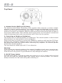
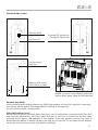
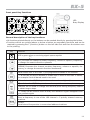
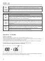
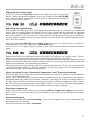
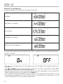
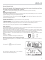
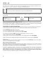
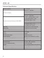
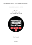
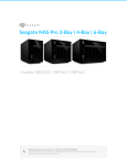
MULTIBAND SCANNING
RECEIVER
User’s Manual
Index
Features
Frequency Band Plan
Frequency table of ALL BAND start setting
German Frequency Band Plan
Frequency table of German Band Plan start setting
Display Functions
Top panel
Operation – in details
Technical Specifications
2
3
4
5
5
6
7
8
12
20
Features
• Polmar RX-5 Scanner is a hand held scanning receiver with 5 bands in the low and high
VHF frequency ranges between 25 and 174 MHz.
• The radio can as well receive FM broadcast radio in the range 87.5 – 108 MHz.
• The world wide AM Air Band between 108 and 136 MHz can be received as well in the new
8.33 kHz channel system and with the standard 25 kHz system.
• For users in Germany RX-5 has pre programmed German band parameters, which make
it very easy to find the typical German radio networks and their stations.
• A standard BNC antenna socket allows connection of typical 50 Ohm type plug-in antennas, external antennas or antenna cables.
• For long battery life, the scanner can be equipped with 3 large AA alkaline batteries or
Ni-MH rechargeable batteries as well.
• The scanner can be operated via batteries or external DC power supply. If rechargeable
batteries are used, these batteries can be charged from the DC power supply as well (the
radio has a switch Alkaline Ni-MH).
• Mono type 3.5 mm headset and extension speakers can be connected.
Important Notes and Warnings
Any changes or modifcations in construction of this device which are not especially approved by the manufacturer could void the conformity compliance and user’s authority to
operate the equipment. Please use only manufacturer- approved accessory items.
Never try to charge non rechargeable batteries and never mix different kind of batteries.
PRECAUTIONS
Read carefully this manual before use the receiver. Keep this manual.
Maintenance must be carried out by qualified personnel only.
Do not use the transceiver or recharge the batteries in an explosive atmosphere
(presence of gas, dust, fumes, etc.).
Switch the receiver off while refuelling or when at a petrol station.
Do not tamper with or attempt to modify the receiver.
Do not place the receiver in excessively dusty places or on unstable surfaces.
Hearing damage! If you are using headphones or earphone headsets etc. for reception, limit the volume level. Prolonged listening at high volume will damage your
hearing. If you hear a buzzing noise in your ears after use, turn the volume down or
stop using the headphones.
Do NOT power the device with alternating voltage as it will damage the receiver, in
addition to posing a risk of fire.
3
Frequency Band Plan
European Frequency Band Plan
This band plan can be used in all regions of Europe. The default settings of this band plan
are suitable for many regions, but it can be necessary to select other frequency steps in
certain regions. The European Frequency Band Plan is more suitable for qualified users who
know already which setting parameters they need.
• The receiver has the German Band Plan as default setting. But the European Band Plan
setting is easily available via pressing
• F, release the button (display shows FC) and then press REGION for longer than 2
seconds.
The two band plans can be toggled without loss of the settings or the memory.
Note:
It is not possible to switch the band plans as long as the scanner is in memory mode.
4
Frequency table of ALL BAND start setting
• The table shows, in which sequence the bands appear in the display after repetitive pressing
of the BAND key.
Band
Name
Air
VHF
CB10
Frequency Range
Mode (s)
(MHz)
108.00~136.9916
AM
144.00~173.9875
default step
8,33 kHz
FM
FM
25.0000~29.9900 (default)
AM
12,5 kHz
10 kHz
+ 5 kHz Offset
VLB
66.000~87.4875
FM
12,5 kHz
WFM
87.50~107.95
WFM
50 kHz
Possible
step settings
8.33 / 25 kHz
5, 10, 12.5,
20, 25KHz
10 kHz with
or without
5 kHz offset
5, 10, 12.5, 20,
25 kHz
50/100
Application
AIRCRAFT
2m Amateur,
Marine Radio,
Freenet and
commercial
band
CB + 10
METER
VHF low band
“4 m Band”
FM Broadcast
Radio
• Within each of the selected bands, you can use the UP / DOWN buttons to select
frequencies with the default channel spacing
German Frequency Band Plan
This is the specially pre programmed band plan with typical German radio communication
network settings. Especially the VHF LOW Band parameters (4 m Band) in Germany use a
20 kHz channel spacing system with an offset of + 15 kHz compared to not shifted generic
20 kHz systems of other countries. The German band Plan is the best choice for users who
want to receive and save typical German radio frequencies.
• The Band Plan setting is available via pressing F and then REGION for longer than 2
seconds.
The two band plans can be toggled any time without loss of the settings or the memory
with the same method between or reverse.
and
Fig. 1
Fig. 2
5
Frequency table of German Band Plan start setting
• The table shows, in which sequence the bands appear in the display after repetitive pressing of the BAND key.
Band
Name
Default step
Possible
step settings
Application
50 kHz
50/100
FM Broadcast
Radio
8.33/25
AIRCRAFT
WFM
88.00~107.95
WFM
Air
108.00~136.9916
AM
144.00~145.9875
FM
12,5 kHz
5, 10, 12.5, 20,
25 kHz
2m Amateur
Band
156.000~162.025
FM
25 kHz
25 only
VHF Marine
Band
CB10
26.5650~27.405
AM
10 kHz
10 kHz with
or without
5 kHz offset
VLB
84.0150~87.225
FM
20 kHz with
15 kHz offset
20 kHz only
VHF
6
Frequency Range
Mode (s)
(MHz)
8,33 kHz
CB Radio with
German 80 CH
System
4 m VHF
low band (BOS)
Display Functions
“VHF”
Indicates that the 2m
VHF band 136~174 MHz
is selected.
“AEREA”
Indicates that the AIR band
108~136 MHz in AM
is selected.
“WFM”
Indicates that the wideband FM band (broadcast radio) 87.5-108 MHz is
selected.
“CB10”
Indicates that the CB radio band with 10 kHz steps is selected.
“VLB”
Indicates that the VHF low band (the 4 m band) is selected.
“PRI”
Indicates that the Priority channel is selected.
“AM”
Indicates that the AM modulation mode is selected.
“♪ ”
Indicates the “key beep” on selected.
“SKIP”
Indicates that the selected frequency is locked out from scanning and
“skipped” during search or scan mode.
Indicates that the keylock function is selected.
“DLY”
Indicates that the “SCAN start DELAY” function is selected.
“HOLD”
( = “ STOP ” ) Indicates that the “SCAN STOP HOLD” is selected.
“VOL”
Indicates the “VOLUME CONTROL” function selected.
“SQ”
Indicates the “SQUELCH CONTROL” function selected.
“
“BUSY”
“
Indicates the battery condition. Full segment means a fully charged
battery. If the batteries become discharged, the indicator will start to
twinkle and a beep sound can be heard every 5 seconds.
Indicates that a signal is being received.
The receiver shows a ten segment incoming signal meter on the
LCD. When receiving a signal, the meter will indicate how strong the signal is. A weak signal will be indicated by one or two segments, while a
very strong signal will have 8 to 10 segments.
“ FC”
Indicates that the Function Key has been pressed and the radio is in the
second key function level.
“ MR”
Indicates that a memorized channel is selected. The channel number
will appear in the small 7 segment channel number display (up to 200
memory locations).
7
Top Panel
1
2
3
1. Antenna Socket (BNC type 50 Ohms)
The antenna socket allows connection of the supplied rubber antenna or another suitable
external or plug-in scanner antenna. The supplied antenna provides good receiver performance over the whole receiving frequency range. To attach the BNC antenna plug to the
socket on the top of your scanner, align the slots around the antenna plug with the tabs on
the scanner’s BNC socket. Then slide the antenna plug down over the scanner’s socket and
rotate the antenna plug’s outer ring clockwise until it locks into the position.
2. Connecting an Earphone/Headphone
This socket is for an external speaker or headphones. The internal speaker is disconnected
automatically if an external device will be plugged in.
Please note that you should not connect any headset or earphone with less than 32 Ohms,
because lower impedance headsets may be too loud when volume is turned too high. Please always start with low volume before connecting any earphone. An external speaker
should have at least 16 Ohms.
The plug should be MONO type with 3.5 mm diameter.
Warning!
If you connect an external speaker to the scanner’s headphone jack, never connect a speaker which has an external grounding. For technical reasons, any device connected there
must be free of any ground. A grounded device may damage the scanner.
3. ON OFF Power button
Press this knob about 2 seconds to switch the scanner on or off. A melody will sound and
the LCD will show the selected Band Plan System before receiving starts. The scanner
always remember the last used setting after switching on.
8
Detailed side views
Monitor MON
Function FC
External DC socket for
Charger & Operation
Pull to unlock
belt clip
Battery slide cover,
Slide down to open
Switch up when using Alkaline batteries.
Switch down when using Ni-MH batteries.
Monitor key MON
While pressing and holding monitor key MON, the speaker is turned on (squelch is opened),
everything can be heard, the actual squelch setting is disregarded.
To exit monitor mode, release MON.
Second Function key F
Second key functions (printed above the keys) can be activated by pressing the F key first
and then the desired key. The first (main) function of each key is printed on the key. After
pressing the F button, FC appears in the display. Press the second function key (this is
always printed above or below a button) as long as you can see FC activated on the display.
Some second functions need a long button pressing!
9
DC Supply and charging socket 8-18 V DC, center contact = +
Allows for using external DC wall charger, supply adapter or cigarette lighter cable. The
supply voltage has a wide range from 8 to 18 Volts. Charging current and internal supply
voltage inside the scanner is automatically regulated.
A suitable typical 230 V power adapter can be 9 Volt / min. 300 mA., a cigarette lighter
cable for 12 V allows direct connection (center pin = +)
Full charging time is about 12 hours for 3 x AA Ni-MH cells inserted.
DC battery type selector
On the left side inside the battery compartment you will find the selector switch with AL
(= Alkaline) and MH (= Ni-MH rechargeable batteries) positions. In case of Ni-MH cells are
used, please switch the battery selector to Ni-MH.
The external DC socket works only in Ni-MH position. If you use the scanner only with
external power for longer time period, we recommend to take out the Ni-MH batteries.
For safety reasons, the external DC socket is disconnected in Alkaline Battery switch position, because Alkaline batteries are not allowed to be charged and can leak or even explode
if you should try to charge such batteries.
Attaching the Belt Clip
To make your scanner easier to carry when you are on the go, use the supplied belt clip.
Slide the belt clip into the hanger piece on the back of the scanner. To remove, slide up the
belt clip pulling the lock pinch at the middle of the belt clip.
Important Notes about rechargeable and not rechargeable batteries:
You can use all types of AA size batteries in the scanner. Standard batteries, available in
any shop, are Alkaline types, have different capacity and life time depending of the price
category of these batteries. Such batteries are not rechargeable and can create a risk, if
you should try to charge them.
Rechargeable batteries are offered in most cases as Ni-MH batteries with a capacity between 1000 mAh and even up to about 2500 mAh. Such batteries can be charged in external
charging devices or inside the scanner via suitable charging cable from 12 V or via AC
adapter from 230 V.
There are also rechargeable Alkaline-Manganese batteries on the market. These batteries
need a special charger (only chargers recommended by the battery manufacturers can be
used) and cannot be charged inside the scanner.
Before inserting Alkaline or rechargeable batteries:
• Make sure that the power is off
• Remove the belt clip- if attached
• Open the battery compartment (slide down the battery compartment cover)
• Install three batteries in the compartment as indicated by the polarity symbols (+ and -)
marked inside.
• Bring the battery switch in the correct position
• Never mix old and new batteries or Ni-MH and Alkaline batteries together
• Use only fresh enough batteries, and remove empty batteries immediately from the scanner, otherwise they can leak and destroy the scanner.
10
Front panel Key Functions
DELAY
B.SE
T
REGION
STEP
LED
Busy Display
/
SAVE
PRI
FM/AM
B.SET
DELAY
STEP
/
SAVE
CURSOR
REGION
PRI
FM/AM
CURSOR
General description of the key functions:
• All functions printed directly on the buttons can be reached directly by pressing the button.
• Functions which are printed above or below a button are secondary functions and can be
reached by pressing the F (function) button on the left side first and then the button near
to the printing.
Key
Function
LED is green when a receiving signal opens squelch
(UP) Increase the channel number, frequency, volume or squelch, frequency,
or change the search direction upwards.
(DOWN) Decrease the channel number, frequency, volume or squelch, frequency, or change the search direction downwards.
Band selects one of the max. 5 pre programmed bands of the scanner
F + B.Set can be used to disable or enable one or more of the max. 5 bands,
for example if not all bands need to be used.
VOL switches the UP/DN keys to be used as volume higher / lower
SQ switches the UP/DN keys to be used as squelch more close / more open
CURSOR can be used to change the decimal point during frequency search
to obtain larger steps.
F + Delay can be used to insert a delay time between signal disappears and
scan restarts again
F + Save
Store a frequency in one of the 199 channel + 5 priority channel memory
locations
RECALL
Recall stored frequencies in memorized address locations
11
F (press 3 seconds) + REGION selects between European standard programming and the German pre programmed search bands and reverse.
Start-Stop is used to start or stop scanning or frequency search process
Key
Function – short description
F + Pri selects priority channels (if programmed)
SKIP: If you do not want the scanner to stop at the displayed frequency or
channel, press SKIP to lock-out (mark) the frequency. During next scan or
search process the scanner will not stop there.
F + Step selects the channel spacing in the present band. In some preprogrammed German bands, the channel steps used there are fixed and
cannot be changed. In the European setting, all possible channel steps can
be selected.
Lamp: switches the background illumination on
F + FM/AM selects between FM and AM mode, where necessary (for example
in the CB band. In some bands (air band or VHF high band) the modulation
is fixed to the system which is in use there and cannot be selected.
BEEP allows keyboard click sounds or disables them
Operation – in details
Power on and off
Make sure the scanner’s antenna is connected before your turn it on.
• Press and hold PWR button on Top panel for 2 seconds. The scanner will turn on after a
short internal test and a start melody can be heard.
• The scanner memorizes the last band and other settings which had been in use before.
A new scanner will start with the factory default Air Band setting.
A limited frequency range will appear in the display.
The Scanner will automatically start “scanning” (this means an automatically frequency
scan will start to discover used frequencies within this range).
12
Adjusting the volume level
Press the combined VOL-SQ button once. Now you have 10 seconds
time to select the desired speaker volume by means of the UP-DOWN
keys. You can see in the display the bar graph in the lowest line showing
the selected volume steps:
Adjusting the squelch level
The squelch of a two way radio shall suppress undesired noise on channels or frequencies
where just no receiver signal is present. As soon as a signal will be received, the squelch
opens and the loudspeaker will reproduce the audio signal. The squelch can be adjusted
from very sensitive (or even open) to more tight levels, where the radio has a certain immunity against interference or far away signals. You can select the squelch setting as you
did it with the volume.
Press the combined VOL-SQ button twice. Now you have 10 seconds time to select the
desired squelch level by means of the UP-DOWN keys.
You can see in the display the bar graph in the lowest line showing the selected volume
steps:
Please note that in the maximum sensitive position the squelch can remain open. This position can be used in cases, where the received signal should be very weak.
But the correct position of the squelch level is important during scanning, because an open
squelch means automatically a scan or search stop. So you should decide which is the best
setting dependent on your present local position.
The best setting can also change with your antenna environment. If you are in an area with
strong interference signals, it may be necessary to keep the squelch more closed than in a
rural area far away from transmitting stations.
Short introduction into “Searching Frequencies” and “Scanning Channels”
The first thing you do with the scanner during first time use is to search for busy frequencies in the selected band(s).
If you are in Germany, you may note that the scanner offers you a special German preprogrammed band plan setting for German networks. The reason is that in Germany some radio services use different channel spacing and frequency offsets compared to other countries. Our unique pre-programmed search bands make it very easy to find the transmissions
there, because the scanner starts immediately with the correct settings.
Searching frequencies
Searching means simply checking a certain band or frequency range for transmissions. If you do not know where to find stations, just start at one band and continue
the search.
Scanning channels
Scanner specialists talk about scanning, if you let the scanner only check previously stored frequencies for activity.
Stored frequencies are called “channels”.
13
Selection of the Band (s)
As factory default, all 5 bands are activated. These are:
Air Band
VHF Band (2 m Band)
CB 10 Band
VLB Band (4 m Band)
WFM Band (FM broadcast)
You can choose whether all bands should remain active or whether you do not need all the bands.
• Press F + B.SET
• You see now the band name of one band on top of the display. The example shows the
AIR Band
• Use UP / DOWN keys to select between on and off, if you wish to deactivate a band. ON
and OFF shows the status of the selected band.
• Repeat this procedure for each band you wish to activate or deactivate. You can select the
bands one after the other by means of the BAND key
• It is possible to delete all bands except one band – one band must remain active. If you
have already deactivated 4 of the 5 bands and try to deactivate the last band, you will
hear a warning sound (1 low and two high tones)
14
Normal Search Mode
So you first search, find frequencies, put them into memory locations and later
you recall or scan the memorized “channels”
means: starting and stopping the search process at any time manually.
Starting Frequency Search
If the squelch is adjusted correctly, the radio will also stop automatically as soon as it finds
a station talking on the just checked frequency.
If the squelch is open, then each pressing on
frequency displayed before.
will only add one frequency step to the
You can now decide to:
• Restart the scanner, if the communication is not interesting
• Stop the scanner, note the frequency on paper for later use or save the frequency into a
memory location
• Wait until the signal disappears and then let the scanner automatically resume
In this last case it may be important to know the DELAY function.
Delay selection
If one partner stops the conversation, then in most cases it will take a small moment until
other partner station continue the communication.
If you would not consider any delay in scanning restart, the scanner would start immediately and would not find the answering stations. So it is usually necessary to allow the
scanner a delay of some seconds before it resumes searching or scanning again.
You can program 0 ( this means delay off) to 5 seconds as delay, before the receiver starts
again.
• Press F + DELAY
• Press UP or DOWN to change the delay time
Storing a Frequency into a memory location
At any stopped frequency it is possible to save this frequency into one of the memory
locations.
Just press F +
to save the frequency.
blinking frequency and memory location
The frequency display and a free location
number will blink subsequently.
15
You have now 2 choices: You can accept the proposed memory location number or you
select another location number by using the UP/DOWN buttons.
The memory location number will change to the desired value
If you accept the proposed or selected memory location number, you accept the setting
by pressing
1 x the
SAVE / RECALL
button again.
You can store up to 200 channels in this way.
Please note following advise: Please store only frequencies in memory locations, which you
are allowed to listen legally. It depends from country to country whether it can be allowed
or not to have for example a local police frequency in a memory
Direct Editor for known frequencies:
If you know the desired frequency already and do not like to scroll through all frequencies
to this frequency, then you can use the direct entry method with cursor function.
• Press VOL-SQ longer than 2 seconds
• The first changeable digit will flash like a cursor
• You can change the value of this digit with UP- DOWN
• To change the blinking digit to another digit position use the F button ,
• then change digit position by UP DOWN
• then press F once more and change value in the digit position with UP DOWN.
Finally, after having changed all digits to the desired value, press long time VOL-SQ
Please note:
to avoid confusion, you can insert a pause by using 2 seconds VOL-SQ to stop (save) and
continue the programming process again.
Skip undesired Frequencies
During any search you will find frequencies with signals, which you do not need to observe
later again. These can be permanent transmissions by uninteresting services, but it can
also be that the scanner has found a so called “birdie”
A birdie is a phantom signal - it seems to be a received signal, but can be an interference
signal generated inside the scanner by an unintended mixing process in CPU, oscillators or
other stages of the circuit. It is technically not possible to make a receiver totally free of
birdies. During the scanner development we try to reduce the birdies as much as possible
or shift a birdie to a frequency which is known as not in use at all.
16
The scanner allows you to skip undesired frequencies from search or scanning.
• Just press SKIP on such a frequency and the frequency will be marked on the ´display
with “SKIP”
• During next search cycle the scanner will not any more stop on this frequency.
• To disable the skip function again, just go to the desired frequency and press SKIP once
more - you will see SKIP disappearing from the display.
Memory Scanning
Now you have successfully saved a couple of frequencies into the scanner’s memory locations. If you like to check only these stored frequencies, then press RECALL and press
Start-Stop to start, stop or restart the scanning.
Hints:
• If you do not have any frequency stored in the scanner’s memory, the display will show
No.dAtA
• If the scanner picks up too much noise or stops at noisy signals, you should increase the
squelch level setting.
• To listen to more distant stations, it may be necessary to reduce the squelch level or to
use the MONITOR key on the left side to open the squelch.
• When the scanner finds a transmission, it will stop there. To avoid a too early restart after
a signal disappeared, we recommend to add a delay of some seconds.
• Please note that scanner specialist have a special name for stored frequencies: they
call them now channels.
• Scanning channels means: scanning all memory locations one after the other for
known stations.
• Searching means: scanning the bands from a start frequency to a stop frequency for
Frequencies which are just in use or for still unknown stations.
Setting the frequency steps:
In the German pre programmed band plan, the frequency steps are pre-defined (e.g. in
the 4 m Band)
In other bands, it is possible to change the steps according to the transmission parameters which are used there.
• Where necessary, go to the desired band and change the steps with the keys F + STEP
and select with UP/DOWN. In all bands, the possible steps may be different.
• The step selection may be especially useful in the CB band, because CB is using worldwide
10 kHz steps with + 5 kHz offset (the display shows “5 ”), and only in Poland they use 10
kHz without any offset, where the display shows “0 ”.
17
Priority ON/ OFF
You can program up to 5 special channels which may be more important for you compared
to other channels. Such channels can be stored into memory locations P1 – P5.
• These channels P1 to P5 will be only checked if the Priority Function is switched on.
• If the Priority function is not on, then the normal scanning does not include these channels. in that mode they are hidden.
The difference between priority and normal channel can be observed in cases were many
channels are stored. Then during scanning, the priority channels will be inserted into the
scanning sequence at least every 2 seconds. So these channels are more often checked
than others.
Please note that the Priority function is only available if at least 1 frequency or more are
already saved into normal memory locations as well.
Activating Priority Mode
• First store one or more frequencies into memory on memory locations P1 …..P5
• Press F + PRI
• In the display appears PRI
To deactivate the PRI mode, repeat the same procedure. In that case PRI will disappear
from display.
If you start now the scanning process, the radio will also check the PRI channels P1..P5
with a higher priority (more often) than the other channels 1…..200. Channels P1…P5 are
inserted (and repeated) into the scanning process at least every 2 seconds.
Backlight
• For using the illumination, press the lamp button.
• The display will stay illuminated for about 15 seconds
.
FM-AM switching
In the AIR band and the other VHF bands the switching between FM, AM and WFM modulation odes works automatically, because each band is internationally associated with only
one possible modulation mode.
In the CB 10 band both modulation modes are possible. Truck drivers use only AM, while
other CB users in central Europe often use FM.
• To toggle between the modes press F + AM/FM key
• If you select AM, an AM icon appears on the display and the letter A appears as first digit
of the frequency display like A26.965
• If you select FM, the letter F appears as first digit of the frequency, for example F26.565
18
Other important functions
Factory Reset Options
If the scanner should show any malfunction, which cannot be solved by replacing the batteries or switching OFF- ON, we prefer to use the reset to the factory default functions. Please
note that this procedure clears all memories and settings (except the German Band and All
Band setting). So use the reset function only in cases where nothing else could help.
To reset to factory default conditions
• Turn the scanner OFF or take out and re-insert batteries, if there is no reaction.
• press MONITOR + F key and switch the scanner ON at the same time, while keeping
the buttons pressed.
• Release all buttons as soon as the scanner is ON. (while switching on, the display shows
that the scanner is initialised).
After Factory Reset, the scanner starts like a new scanner with German Band setting and
AIR Band.
Memory Reset
It may be useful to erase the memories completely in one step, if necessary.
To reset the memory and keep all other settings
• Press F
• Release F and then keep BEEP pressed for at least 2 seconds
• in the display rE SEt appears.
Keylock function
• Press F + MONITOR
• the key symbol appears
• to unlock repeat the same procedure, the symbol will disappear
Display test mode
• Keep UP and LAMP pressed during power on. For a short moment, all display Icons will
be on for check.
19
Technical Specification
Memory channels
200 channels
WFM: 87.5 - 108 MHz
VHF: 144 - 174 MHz
Frequency Ranges
VLB: 66 - 88 MHz
AIR: 108 - 136 MHz
CB: 0,25 - 29,69 MHz
87.5000 - 88 MHz (WFM): 0.9 μV
107,950 MHz (WFM): 0.9 μV
108.050MHz (AM): 0.4 μV
Typical Receiver Sensitivity at 12dB SINAD
135.500MHz (AM): 0.4 μV
144.020MHz (FM): 0.3 μV
173.450MHz (FM): 0.3 μV
27.405MHz (FM): 0.9 μV
Scan rate
25 channels per second (Normal)
Search rate
25 steps per second (Normal)
Priority sampling interval
2 seconds
IF Rejection
65dB
1’st IF
51.750MHz
2’nd IF
450KHz
Internal audio output
1 Watt at 16 ohms
Internal speaker
dynamic 40mm diameter, 16 ohms
DC Current at closed squelch
35 mA
Current drain with full audio output
max 250 mA
Battery power requirements
Alkaline AA x 3 or Mi-MH AA x 3
Antenna socket
50 ohms - BNC connector
External headphone socket
3.5mm Mono type
Weight
110 g (without batteries and Antenna)
Size
56 (W) x 27 (D) x 106 mm (H)
Ext. DC power supply
8…..18 V DC, center +
DC charge current in MH switch position
max 150 mA
20
40
Dichiarazione
di Conformità
IT
Con la presente, la Polmar srl dichiara
che questo ricevitore di marca Polmar
mod. RX-5, è conforme ai requisiti essenziali ed alle altre disposizioni pertinenti
stabilite dalla Direttiva 1999/5/CE.
DE
Hiermit erklärt Polmar srl daß sich das Gerät
RX-5 in Übereinstimmung mit den grundlegenden Anforderungen und den übrigen
einschlägigen Bestimmungen der Richtlinie
1999/5EG befindet.
EN
Hereby Polmar srl, declares that this receiver brand Polmar, mod. RX-5 is in compliance with the essential requirements
and other relevant provisions of Directive
1999/5/CE.
ES
Por medio de la presente Polmar srl declara que el RX-5 cumple con los requisitos y
cualesquiera otras disposiciones aplicables
o exigibles de la Directiva 1999/5/CE.
NL
Hierbij verklaart Polmar srl dat het toestel
RX-5 in overeenstemming is met de essentiële eisen de andere relevante bepalingen
van richtlijn 1999/5/EG.
MT
Hawnhekk, Polmar srl, jiddikjara li dan RX-5
jikkonforma mal--h tiġijiet essenzjali u ma
provvedimenti o-hrajn relevanti li hemm fidDirrettiva 1999/5/EC.
PL
Niniejszym Polmar srl oświadcza, że
RX-5 jest zgodny z zasadniczymi wymogami oraz pozostalymi stosownymi postanowieniami Dyrektywy 1999/5/CE.
Elenco degli stati dove l’apparato
può essere utilizzato
List of intended countries of use
Questo simbolo, aggiunto al numero di serie, indica che l’apparato risponde pienamente ai requisiti della Direttiva Europea delle Radio e Telecomunicazioni 1999/05/EC, per quanto concerne i terminali radio.
This symbol, on the serial number seal, means that the equipment complies with the essential requirements on the European Radio and Telecommunication Terminal Directive 1999/05/EC.
41
USER INFORMATION
In accordance with art. 13 of the Legislative Decree of 25th July 2005, no. 15 ”Implementation of
Directives 2002/95/EC, 2002/96/EC and 2003/108/EC, relative to reduction of the use of hazardous
substances in electrical and electronic equipment, in addition to waste disposal”
The crossed bin symbol shown on the equipment indicates that at the end of its working life
the product must be collected separately from other waste.
The user must therefore take the above equipment to the appropriate differentiated collection
centres for electronic and electro technical waste, or return it to the dealer when purchasing a new
appliance of equivalent type, in a ratio of one to one.
Appropriate differentiated waste collection for subsequent recycling, treatment and environment-friendly disposal of the discarded equipment helps to prevent possible negative environmental and health
effects and encourages recycling of the component materials of the equipment.
Illegal disposal of the product by the user will be punished by application of the administrative fines provided
for by the legislative decree no. 22/1997 (article 50 and following of the legislative decree no. 22/1997).