1
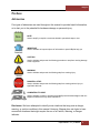
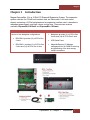
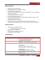
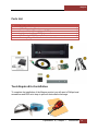
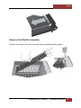
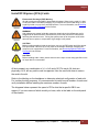
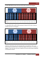
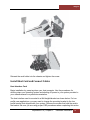
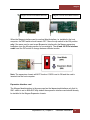
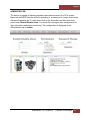
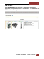
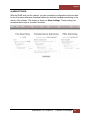
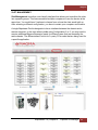
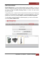
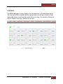
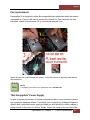
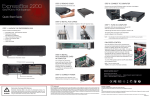
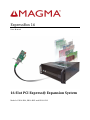
ExpressBox 16 User Manual 16 Slot PCI Express® Expansion System Models: EB16-BX4, EB16-BX8 and EB16-SX8 Magma Table of Contents Preface 4 Advisories 4 Safety Instructions 5 Chapter 1 Introduction 7 Basic Features: 8 Smart Features 8 Specifications 8 Pre-Installation Information 9 Parts List 10 Tools Required for Installation 10 Chapter 2 Hardware Installation 11 Open Enclosure 11 Remove Card Holder Assembly 12 Install PCI Express (PCIe) Cards 13 Install Host Card and Connect Cables 16 Power on Expansion Chassis 21 Power on Computer 22 Verify Installation 22 System Should Be Up and Running 28 Finishing Touches 28 Chapter 3 Advanced Technical Information 28 PCIe Card Power Consumption 28 Redundant Power Supply Option 29 Interface Cards 31 x16 Host Interface Card: 31 x8 Host Interface Card: 33 16 Slot Backplane: 33 Power Management Backplane: 33 Backplane Power Indicator: 34 ExpressBox 16 | 2 Magma Activity Indicator: 34 Status Indicators and Configuration Switches – ExpressBox 16 Smart Only 37 Chapter 4 Express I/O Manager 38 WEB Server and SNMP Features 38 WEB access and SNMP Configuration 38 Configure Network Settings 39 Chapter 5 Chassis Maintenance 48 Chassis Cleaning 48 Fan replacement 50 “Hot-Swappable” Power Supply 50 Chapter 6 Troubleshooting 52 Locate the Problem 52 Computer Hangs During Power Up 52 Computer Doesn’t Detect Expansion Chassis 53 Add-in card doesn’t work 54 Support for 3rd Party Cards 55 Windows Error Codes 55 Computer Hangs After Many Cards Installed 57 Nothing Works 57 Chapter 7 How to Get More Help 58 Frequently Asked Questions (FAQ) 58 Contacting Technical Support 58 PCIScope Software Utility for Windows XP and 2003 Server 59 Returning Merchandise to MAGMA 60 Appendix A Compliance 61 ExpressBox 16 | 3 Magma Preface Advisories Five types of advisories are used throughout this manual to provide helpful information, or to alert you to the potential for hardware damage or personal injury. NOTE Used to amplify or explain a comment related to procedural steps or text. IMPORTANT Used to indicate an important piece of information or special “tip” to help you CAUTION Used to indicate and prevent the following procedure or step from causing damage to the equipment. WARNING Used to indicate and prevent the following step from causing injury. DANGER or STOP Used to indicate and prevent the following step from causing serious injury or significant data loss COMPATIBILITY ISSUE Used to indicate a known or potential compatibility issue between Magma and nonMagma hardware that may cause malfunction. Disclaimer: We have attempted to identify most situations that may pose a danger, warning, or caution condition in this manual. However, Magma does not claim to have covered all situations that might require the use of a Caution, Warning, or Danger indicator. ExpressBox 16 | Preface 4 Magma Safety Instructions Always use caution when servicing any electrical component. Before handling the Magma Expansion chassis, read the following instructions and safety guidelines to prevent damage to the product and to ensure your own personal safety. Refer to the “Advisories” section for advisory conventions used in this manual, including the distinction between Danger, Warning, Caution, Important, and Note. Always use caution when handling/operating the computer. Only qualified, experienced, authorized electronics personnel should access the interior of the computer and expansion chassis per UL and IEC 60950-1 The power supplies produce high voltages and energy hazards, which can cause bodily harm. Use extreme caution when installing or removing components. Refer to the installation instructions in this manual for precautions and procedures. If you have any questions, please contact Magma Technical Support. WARNING Never modify or remove the radio frequency interference shielding from your workstation or expansion unit. To do so may cause your installation to produce emissions that could interfere with other electronic equipment in the area of your system. When Working Inside a Computer 1. Before taking covers off a computer, perform the following steps: 2. Turn off the computer and any peripheral devices. 3. Disconnect the computer and peripheral power cords from their AC outlets or inlets in order to prevent electric shock or system board damage. In addition, take note of these safety guidelines when appropriate: To help avoid possible damage to systems boards, wait five seconds after turning off the computer before removing a component, removing a system board, or disconnecting a peripheral device from the computer. When you disconnect a cable, pull on its connector or on its strain-relief loop, not on the cable itself. Some cables have a connector with locking tabs. If you are disconnecting this type of cable, press in on the locking tabs before disconnecting the cable. As you pull connectors apart, keep them evenly aligned to avoid bending any connector pins. Also, before connecting a cable, make sure both connectors are correctly oriented and aligned. ExpressBox 16 | Preface 5 Magma CAUTION Do not attempt to service the system yourself except as explained in this manual. Follow installation instructions closely. Protecting Against Electrostatic Discharge Electrostatic Discharge (ESD) Warning Electrostatic Discharge (ESD) is the enemy of semiconductor devices. You should always take precautions to eliminate any electrostatic charge from your body and clothing before touching any semiconductor device or card by using an electrostatic wrist strap and/or rubber mat. Static electricity can harm system boards. Perform service at an ESD workstation and follow proper ESD procedures to reduce the risk of damage to components. Magma strongly encourages you to follow proper ESD procedures, which can include wrist straps and smocks, when servicing equipment. You can also take the following steps to prevent damage from electrostatic discharge (ESD): · When unpacking a static-sensitive component from its shipping carton, do not remove the component’s anti-static packaging material until you are ready to install the component in a computer. Just before unwrapping the anti-static packaging, be sure you are at an ESD workstation or are grounded. · When transporting a sensitive component, first place it in an anti-static container or packaging. · Handle all sensitive components at an ESD workstation. If possible, use antistatic floor pads and workbench pads. · Handle components and boards with care. Don’t touch the components or contacts on a board. Hold a board by its edges or by its metal mounting bracket. ExpressBox 16 | Preface 6 Magma Chapter 1 Introduction Magma ExpressBox 16 is a 16-Slot PCI Express® Expansion System. The expansion system consists of a PCIe® host interface card, an iPass cable, a 4U rack-mount chassis containing a 16 Slot backplane and an expansion interface card, a standard or redundant power supply, and high volume cooling fans. There are two versions available: ExpressBox 16 Basic and ExpressBox 16 Smart. ExpressBox 16 Basic ExpressBox 16 Smart A choice of two backplane configurations: · · EB16-BX4: provides (16) x4 PCIe Gen 2 slots EB16-BX8: provides (2) x16 PCIe Gen 2 slots and (14) x8 PCIe Gen 2 slots. · Backplane provides (2) x16 PCIe Gen 2 slots and (14) x8 PCIe Gen 2 slots · LED Status Panel · Magma’s Express I/O Manager management tool for SNMP monitoring and partitioning of the slots among multiple computers. ExpressBox 16 | Chapter 1 Introduction 7 Magma Basic Features: · · · · · · · · · · Easy “Plug and Play” installation PCI Express Gen 2 x16 or x8 interconnection All slots support full-length cards Status LEDs on backplane indicate active link, speed (Gen 1 or Gen 2), partial or complete lane training Automatic power-up control by computer Four hot-swappable cooling fans Multiple power supply options with auxiliary power connectors to support cards requiring more than 75 Watts Industrial 4U rack-mount enclosure Card retainers keep cards in place and are adjustable to fit any size card Chassis provides superior EMI control, vibration, shock and moisture resistance Smart Features · · · · All the features of the BASIC model o 14 slots x8 PCIe and 2 slots x16 PCIe Magma Express I/O Manager Constant critical component monitoring Front panel status LED display Specifications Item Technology Backplane Interface Cards Description PCI Express Bus Specification Revision 2.0 PCI Local Bus Specification Revision 2.3 PCI Bridge Architecture Revision 1.2 EB16-BX4 - 16 slots x4 PCIe EB16-BX8 - 14 slots x8 PCIe and 2 slots x16 PCIe Low Profile PCIe x8 Gen 2 Dimensions: 2.70”H x 4.70” L x 0.62”W Power Consumption: 1.2A @ +3.3V (3.96 watts) Interconnect Bandwidth PCIe x16 Gen 2 Dimensions: 2.75” H x 6.95” L x 0.75”W Power Consumption: 1.5A @ +3.3V (5 watts) 40Gbps (x8 Link) 80Gbps (x16 Link) ExpressBox 16 | Chapter 1 Introduction 8 Magma Interface Card Power Consumption Enclosure System Cooling Power Supply Options Environmental MTBF Monitoring ExpressBox 16 Smart only Regulatory Compliance Supported Operating Systems Warranty x8 PCIe: 1.2A @ +3.3V (3.96 watts) x16 PCIe: 1.5A @ +3.3V (5 watts) 4U Rack-mount 19”W x, 7”H x 20”D Removable/cleanable air filter 34 lbs / 15.5 Kg (4) 77 CFM Fans - Hot Swappable 850 Watt, 1700 Watt or 850 Watt Redundant 100-240 VAC, 47-63 Hz Power Input 12V @ 60Amps 3.3V @ 33 Amps Ambient Temperature 0° to 50° C Storage Temperature -55° to 125° C Relative Humidity 0% to 90% non-condensing 850W standard power supply - 185,600 hours 1700W dual standard power supply - 106,600 hours 850W redundant power supply - 720,000 hours Express I/O Manager with built-in web server LED Indicator on front panel SNMP FCC Class A Verified CE RoHS Compliant Windows MacOS Linux 30 day money back guarantee 1 year return to factory Pre-Installation Information Before using the Magma Expansion chassis you should perform the following steps: • • • Inventory the shipping carton contents for all of the required parts Gather all of the necessary tools required for installation Read this manual ExpressBox 16 | Chapter 1 Introduction 9 Magma Parts List Qty 1 1 1 2 1 or 2 1 Item Quick Start Guide 16 Slot Expansion Chassis 3-meter shielded iPass (x8 or x16 PCIe) interface cards (x8 or x16 PCIe) U.S. Standard 115V Power Cord Accessory Bag with rubber feet and card hold down extender # 1 2 3 4 5 6 Tools Required for Installation To complete the installation of the Magma product you will need a Phillips-head screwdriver and ESD wrist strap to prevent electrostatic discharge. ExpressBox 16 | Chapter 1 Introduction 10 Magma Chapter 2 Hardware Installation The following steps will guide you through the installation of your Magma Expansion System. CAUTION Hardware installation shall be performed only by qualified service personnel per UL and IEC 60950-1. Electrostatic Discharge (ESD) Warning All add-in cards are susceptible to electrostatic discharge. When moving cards, it is best to carry the cards in anti-static packaging. If you need to set a circuit card down, be sure to place it inside or on top of an anti-static surface. For more information, see “Protecting Against Electrostatic Discharge” in the Preface. WARNING High voltages are present inside the expansion chassis when the unit’s power cord is plugged into an electrical outlet. Disconnect the power cord from the AC outlet before removing the enclosure cover. Turning the system power off at the power on/off switch does not remove power to components. High voltage is still present. CAUTION Before touching anything inside the enclosure, move to an ESD station and follow proper ESD procedures. Failure to do so may result in electrostatic discharge, damaging the computer or its components. For more information, see “Protecting Against Electrostatic Discharge” in the Preface. Open Enclosure Loosen the 2 thumbscrews that retain the top cover of the chassis and slide the lid towards you as shown below: ExpressBox 16 | 11 Magma Remove Card Holder Assembly Remove the screw on the side of the card holder assembly and lift upwards. ExpressBox 16 | Chapter 2 Hardware Installation 12 Magma Install PCI Express (PCIe) Cards Electrostatic Discharge (ESD) Warning All add-in cards are susceptible to electrostatic discharge. When moving cards, it is best to carry the cards in anti-static packaging. If you need to set a circuit card down, be sure to place it inside or on top of an anti-static surface. For more information, see “Protecting Against Electrostatic Discharge” in the Preface. WARNING High voltages are present inside the expansion chassis when the unit’s power cord is plugged into an electrical outlet. Disconnect the power cord from the AC outlet before removing the enclosure cover. Turning the system power off at the power on/off switch does not remove power to components. High voltage is still present. CAUTION Before touching anything inside the enclosure, move to an ESD station and follow proper ESD procedures. Failure to do so may result in electrostatic discharge, damaging the computer or its components. For more information, see “Protecting Against Electrostatic Discharge” in the Preface. CAUTION Before installing add-in cards, please ensure that the input current rating specified on the AC input label is not exceeded. All slots support any combination of x1, x4, x8 and x16 PCIe cards. All slots are physically a x16, but any add-in card is supported. Use the card hold down to secure the card in the slot. Refer to the labeling on the backplane to determine electrical configuration of each slot. For trouble-shooting purposes, it is recommended to install a small number of cards and verify installation before installing the maximum number of cards. The diagrams below represent the speed of PCIe slots that a specific EB16 can support. If you are unsure of which model you have, refer to the label on the side panel of the chassis. ExpressBox 16 | Chapter 2 Hardware Installation 13 Magma In model EB16-BX4 all sixteen slots are x4 PCIe Gen 2 as shown this diagram: Expansion Slot (PCIe x16) PCIe GEN2 X4 PCIe GEN2 X4 PCIe GEN2 X4 PCIe GEN2 X4 PCIe GEN2 X4 PCIe GEN2 X4 PCIe GEN2 X4 PCIe GEN2 X4 PCIe GEN2 X4 PCIe GEN2 X4 PCIe GEN2 X4 PCIe GEN2 X4 PCIe GEN2 X4 PCIe GEN2 X4 PCIe GEN2 X4 PCIe GEN2 X4 PCIe Switch HOS T SLOT PCIe Switch 1 2 3 4 5 6 7 8 9 10 11 12 13 14 15 16 For Model EB16-BX8 and EB16-SX8 a mixture of x8 and x16 PCIe Gen 2 slots are available as shown in this diagram. HOST SLOT PCIe Switch PCIe GEN2 X8 PCIe GEN2 X8 PCIe GEN2 X16 PCIe GEN2 X8 PCIe GEN2 X8 PCIe GEN2 X16 PCIe GEN2 X8 PCIe GEN2 X8 PCIe GEN2 X8 PCIe GEN2 X8 PCIe GEN2 X8 PCIe GEN2 X8 PCIe GEN2 X8 PCIe GEN2 X8 PCIe GEN2 X8 PCIe GEN2 X8 Expansion Slot (PCIe x16) PCIe Switch 1 2 3 4 5 6 7 8 9 10 11 12 13 14 15 16 Install the cards following the card manufacturer’s recommendations. Some card manufacturers recommend that you install their software driver(s) prior to installing the hardware. If this is the case, be sure to install the PCIe device driver before installation of the expansion chassis. ExpressBox 16 | Chapter 2 Hardware Installation 14 Magma . Make sure that all cards are fully seated in their connectors. When correctly seated in its connector, you will notice a firm resistance when you pull up gently on the card. To keep the cards in place, secure them in the enclosure with their retaining screws (supplied with the Magma Expansion chassis. After securing the cards verify that they do not touch each other. Depending on card size and thickness, you may require mechanical card guides to ensure isolation, such as the case with 2 single full-length PCIe cards. Card guides for this system can be purchased separately from Magma. Re-install card holder assembly and position guides. The plastic guides can be removed and reversed for short cards. Tighten plastic guides with a screw driver. Rotate the plastic pieces until their grooves are aligned with the cards. ExpressBox 16 | Chapter 2 Hardware Installation 15 Magma Reinsert the card holder into the chassis and tighten the screw. Install Host Card and Connect Cables Host Interface Card Begin installation by powering down your host computer. Use the procedures for shutting down your operating system and shutting off power to your system provided in your owner’s manual or system documentation. The host interface card is mounted to a “full-height” bracket as shown below. For low profile case applications, you may need to change the mounting bracket to the low profile bracket that shipped with your system. Remove the screws that hold the card to the bracket. Be sure you are using proper ESD procedures when completing this action. ExpressBox 16 | Chapter 2 Hardware Installation 16 Magma When the host computer is off and all power cords are disconnected from the AC outlet, remove the cover and prepare your host card for insertion into a PCIe slot. There are 2 host cards available for this chassis. To verify which card you currently have, look at the options below. It is important to know how many lanes the host computer slot can support. The host card needs to be configured for the same number of lanes as the host computer slot. For example, the computer slot is set to x8 lanes; therefore, you must configure the Magma host card to x8 lanes. Refer to PAGE 31 & 32 for configuration purposes of the PCIe card. The number of lanes is typically noted on a motherboard computer next to the PCI Express slot. This motherboard calls the red slot a PCIE_x4_4 STOP YOU MUST ONLY INSTALL THE PCIe HOST CARD INTO A PCI EXPRESS SLOT. Only use cards WITH brackets. This will ensure that your PCIe host card can only be inserted into a PCIe slot. Although PCI Express cards without brackets may fit into conventional PCI slots, you run the risk of damaging the PCI Express host card if you insert it into a PCI slot. Please ensure that your host computer has PCI Express slots and install the host card only into a PCI Express slot. ExpressBox 16 | Chapter 2 Hardware Installation 17 Magma Magma x8 host card P/N#01-04978-03 Magma x16 host card P/N#01-5018-00 When the Magma interface card is used as “Host” interface i.e. installed in the host computer, the RED switch should remain OFF. Move the dip switch to the ON position only if the same card is used as an “Expansion Interface” in the Magma expansion backplane (see the following section for more details). The x8 and x16 PCIe interface cards have the DIP switch to change between different modes. Note: The expansion chassis will NOT function if SW2 is set to ON and the card is inserted into the host computer. Expansion Interface card The Magma “host” interface is the same card as the “expansion” interface only that its SW1 switch is set to “ON=EXP.” By default the expansion interface card should already be installed in the Magma Expansion chassis. ExpressBox 16 | Chapter 2 Hardware Installation 18 Magma Depending on the interface cards, a x16 PCIe or x8 PCIe 3-meter iPass cable is included. x8 iPass Cable x16 iPass Cable Carefully position the expansion chassis so that the expansion cable will conveniently reach from the host computer to the Magma Expansion chassis. Cables attached to the expansion chassis must be securely fastened. When you hear a “click,” it is properly secured. If not securely connected, the connectors may cause intermittent or lost connections. ExpressBox 16 | Chapter 2 Hardware Installation 19 Magma NOTE If at all possible, plug all power cords from the expansion chassis and your host computer into a shared power strip, preferably one that has surge and noise suppression circuitry built into it. ExpressBox 16 | Chapter 2 Hardware Installation 20 Magma Power on Expansion Chassis Turn on ALL power supply switches at the rear, then power on the chassis using the green power switch on the front. Check your installation before powering up the Magma Expansion chassis for the first time. Although the power supply has an over voltage protection device built into it, it may not "trip" in time to fully protect a device that has been improperly connected, or whose power cable has been damaged. You must apply power to the expansion chassis BEFORE you power up your computer. This will allow the higher numbered buses in the bus hierarchy to be at a stable state when the host computer issues its master power-on bus reset. Each power supply has an individual power switch at the rear as well as LEDs to indicate its power status. Ensure that the power switch next to the power cord is flipped ON the “|” symbol. This enables the device to turn ON once it is activated through the main POWER SWITCH. The LED on the top should turn on when the power cord is connected to the device from the outlet. In this case the AC POWER LED would turn green. The LED below that is for DC power and should be red until the entire chassis is powered through the main switch or through the host computer for remote power. ExpressBox 16 | Chapter 2 Hardware Installation 21 Magma After first turning on each of the individual power switches in the back of the chassis, the entire system can then be turned on. IMPORTANT A power supply unit (PSU) should be switched off before removal and upon insertion of its replacement. After replacing a PSU, be sure to secure the new one in place with its snapin mechanism for better grounding and noise immunity. NOTE The power supply switch cannot be toggled quickly from ON to OFF after the expansion set is initially powered. There is a few seconds delay to power the device down. Power on Computer To effectively use your Magma chassis as part of your computer system, ensure that all the proper connections are made. Then power on your computer. This will enable your Magma chassis to turn ON. The Magma chassis can also turn ON by itself by pressing the main switch on the front panel and then turning on the computer. Verify Installation Windows No additional software or drivers are needed. The operating system should automatically recognize the Magma expansion chassis. ExpressBox 16 | Chapter 2 Hardware Installation 22 Magma To verify a successful installation on Windows, find the ‘My Computer’ icon and “rightclick” on it. Then select ‘Manage’ from the pop-up menu. Next, click on ‘Device Manager’ in the leftmost Computer Management window. Finally, click on the View Menu and select View Devices by Connection. Open ACPI (BIOS) Open PCI BusClick the ‘+’ sign several times until your reach a PCI Express Root Port with a PCI Standard PCI-to-PCI Bridge beneath it. ExpressBox 16 | Chapter 2 Hardware Installation 23 Magma The Device Manager will display the available slots within the chassis. As reference, you can determine which slot you inserted your PCIe card in by following the outline that is shown below. The Magma chassis has 2 PCIe Switch devices that enable the slots to work: · · The 1st PCIe Switch controls Slots 0,1,2,3,4,5,6 The 2nd PCIe Switch controls slots 7,8,9,10,11,12,13,14,15,16 Note: To view the slots pertaining to the 2nd PCIe Switch you must click to expand Slot 15. ExpressBox 16 | Chapter 2 Hardware Installation 24 Magma If the verification is successful, you can install 3rd Party cards as well as auxiliary peripherals, such as hard drives into the chassis. If, however, the installation was unsuccessful, you may not see the PCI to PCI Bridge, or it will have a small yellow symbol in front of it as shown below, go to Troubleshooting Mac OS For Mac OS X 10.4 or newer, the operating system will automatically recognize the Magma Expansion chassis. Expansion Slot Utility The following screen may be displayed the first time you turn on your computer with the Magma Expansion chassis installed. ExpressBox 16 | Chapter 2 Hardware Installation 25 Magma Mac OS X is prompting you to choose a PCI Express profile that maximizes the performance of your attached devices. The Magma host interface card can communicate up to a bandwidth of x16, x8, or x4 from and to the expansion chassis and devices. Again, you have to verify the configuration of your card. For assistance, refer to Page 31 & 32. You should choose a profile that matches the configuration of all the cards installed in your Mac. Apple System Profiler Select “About This Mac” under the Apple Icon Then click the “More Info” button click on the Devices tab you should see a pcibridge device listed under PCI as shown below: Any cards you install in the expansion chassis will appear behind the pci-bridge device. ExpressBox 16 | Chapter 2 Hardware Installation 26 Magma If any of these devices are not displayed as shown above, you should shut down your system (computer first, then the expansion chassis) and reconnect the cables and the host interface card to ensure that you have a solid connection. Then restart the Magma Expansion chassis followed by the computer. Next, try to verify the installation again, as shown above. If you are still having problems, contact Magma Technical Support at (858) 530-2511. Linux After the expansion chassis has been installed in a Linux-based system, its installation can be verified by typing the following command lines: lspci –t Display the overall structure of the expansion chassis lspci –vv Lists additional information about the PCIe switch (in our case it will list the PLX information). Ispci –vvv Display the most comprehensive information about the expansion chassis. Typical output from lspci –vvv is verbose, but you can dig through the information to find very important information. There are so many registers and settings associated with PCI Express Switches. ExpressBox 16 | Chapter 2 Hardware Installation 27 Magma System Should Be Up and Running Apply power to the Magma Expansion chassis first, then power up the computer. To confirm the card installation(s) in the Windows Device Manager or Apple System Profiler is functioning correctly, your Windows Device Manager should look something like this: If you discover that any of your 3rd Party PCIe cards contain a . You may have a problem with that card. Refer to Troubleshooting for further guidance. IMPORTANT We will provide reasonable technical support with 3rd Party cards. However, if you have verified a successful installation of the Magma Expansion chassis, but experience difficulty installing your 3rd Party cards, the card manufacturer should be able to provide the best support. Finishing Touches After your system is working properly, replace the host computer cover, and the close the lid of the expansion chassis. Chapter 3 Advanced Technical Information PCIe Card Power Consumption ExpressBox 16 | Chapter 3 Advanced Technical Information 28 Magma Be AWARE of the power consumption of any 3rd party card that is inserted into the slot of the device. Each individual slot is capable of outputting 75 Watts of power. If at any time the cards inserted exceed the maximum amount of power that's available from every slot, then one power supply would not suffice. One power supply is capable of producing only 850 Watts of power. Users would need to acquire a second power supply for all slots to work properly. In general, the best support for power-hungry cards requires 1200 Watts (2 power supply units). Each slot is designed to support: 3.0 amps @ 3.3v = 9.9 watts; 5.5 amps @ 12v = 66 watts Redundant Power Supply Option The Power Supply units that are used within this chassis are shared by the electrical components within the chassis. Power is effectively distributed by both units until one unit becomes nonoperational. In this case, the effect of power distribution is shifted to the functional Power Supply. Further information about the Power supply’s electromagnetic capability (EMC) is listed below: ExpressBox 16 | Chapter 3 Advanced Technical Information 29 Magma DANGER or STOP DO NOT TEMPER WITH THE INTERIOR POWER CONNECTIONS THAT LINKS TO CONNECTORS J24 AND J25. IT PROVIDES POWER TO THE ENTIRE BACKPLANE. ONLY USE THE GIVEN CABLE FOR CONNECTION SINCE IT IS NOT AN ATX MODEL ExpressBox 16 | Chapter 3 Advanced Technical Information 30 Magma NOTE CONNECTORS J20, J21, J22, and J23 within the chassis will provide additional power to any PCI Express Card that requires it. The outputs from these connectors are 12V @ 10A each. Users should purchase a MAGMA cable P/N# 01-05996-03 for this capability. The rd connector on the 3 Party PCI Express card that’s compatible with the cable is shown below. Before discussing a troubleshooting methodology for locating the problem we will first introduce several indicators and configuration switches that provide general and specific information for this process. Interface Cards x16 Host Interface Card: The host card has indicators that provide the status of the clock, the power distribution, and the active data lanes. To verify that your expansion device is properly linked to your computer, ensure that these LEDS on the HIF and EIF cards are ON: ExpressBox 16 | Chapter 3 Advanced Technical Information 31 Magma If the card is not transferring or receiving any type of data through its transceiver (iPass connector) then the LOS (Loss of Signal) LED would be turn ON. The width of the active data lanes may vary based on the PCIe slot that you are using for your Magma host interface card. Be sure to check the PCIe slot in your computer to determine how many data lanes it can support. It should be labeled near the slot. The default value that the card is operating in is x16. In order to change the bandwidth of the card, refer to the DIP switch labeled SW100. ExpressBox 16 | Chapter 3 Advanced Technical Information 32 Magma x8 Host Interface Card: The card that is x8-capable (uses x8 iPass cable) contains status indicators that tell users the condition it is currently operating in. There are LED indicators for the lanes that are being used for data transfer and whether the board is powered correctly. A switch is also available to change the amount of lanes that would be operational for usage by the user. 16 Slot Backplane: Power Management Backplane: This backplane system controls the power distribution to the entire PCIe device. Ensure that this device is working properly by indicating that the LEDs are ON. It is attached to the side panel within the chassis near the power supply module. ExpressBox 16 | Chapter 3 Advanced Technical Information 33 Magma Backplane Power Indicator: Other than the indicators on the front panel, the backplane board that’s located within the chassis contains LEDs that provide status of the power supply. These are located by the edge of the board on the top left. If the power is operating in its normal condition, then the LED with the reference designator D34 will light up. Otherwise, if there is a voltage failure (for +3.3V) the D21 LED will lit. This status must be inspected to see whether power is an issue. Activity Indicator: These are the LEDs that tell whether data is processed correctly throughout the entire backplane. LEDs D32 and D33 indicate whether information from the EEPROM has properly transferred the data set to the PLX PCI Express switches when the chassis is initially turned on. These LEDs should go off after a short period of time. The picture on the left is shown before the host computer is turned on and the one on the right is after the host computer is powered. ExpressBox 16 | Chapter 3 Advanced Technical Information 34 Magma Another set of indicators that are useful to observe are D22, D29, and D30. This shows the RESET status of the backplane and the PCIe Gen 2 Switch components. D22 is the RESET status of the entire backplane and D29 and D30 is represents PCIe switches. The RESET status should turn off (LEDs OFF) when the host computer turns on and the chassis is powered. If it does not, then the chassis is having technical difficulties and will not see the cards that are inserted. Below shows the proper status of the indicators. ExpressBox 16 | Chapter 3 Advanced Technical Information 35 Magma Other indicators that are located on the backplane are the LEDs that identify the type of card that is inserted into a slot. This is in regards to the number of lanes and speed that the card possesses. As shown below, the LEDs are located at the bottom of each individual slot. When will the lit LED remain consistent is dependent on whether the inserted card is using the maximum capability of the backplane’s PCIe slot. For example, if the card features a x16 bandwidth and is operating at a Gen 2 speed, once the card is plugged into a x16 slot the lit LED will remain consistent. Otherwise, the card isn’t using the full potential of the slot’s capability and the bottom indicator would blink. The card would still be operational through the backplane, but in any case, the 3rd party card that is operating at Gen 1 and/or contains less transmit/receive data lanes than the slot that it is placed in, the locator LED will blink. ExpressBox 16 | Chapter 3 Advanced Technical Information 36 Magma Status Indicators and Configuration Switches – ExpressBox 16 Smart Only Under normal operating conditions the status indicators are for internal Magma troubleshooting while the configuration switches/jumpers should remain in their default state preset by Magma for best compatibility. However, should a problem occur with the chassis (or a special mode of operation be solicited by the client) we included below explanations as to what all these items are and how they should be treated: Status Panel indicators: All LED’s should be green at all times. An orange LED means a fault of the corresponding item listed in the picture above. If the chassis is functioning improperly, you have the option of resetting the entire system by pressing and holding the Alarm Reset button (shown in the above diagram) until the LEDs blink. The color of the LEDs will turn orange. This will enable the entire device to reboot to its default settings. You can only do this once the chassis is turned off, but still operates on standby power. So, ensure the power cable is connected between the chassis and the AC outlet. ExpressBox 16 | Chapter 3 Advanced Technical Information 37 Magma Chapter 4 Express I/O Manager ExpressBox 16 Smart contains extra features that could be utilized to monitor the status of the components on the backplane and the items in the chassis such as the state of the power supplies, fan status, and temperature. It is observed on a remote computer that would indicate when an equipment malfunction has occurred. This product can be divided into multiple individual groups of I/O supporting 4 independent host computers through partitioning and purchasing additional host/expansion link cards and cables. WEB Server and SNMP Features ExpressBox 16 Smart supports the Simple Network Management Protocol (SNMP) for remote monitoring and administration by offering the following features: · · · · · · · · · Internal Temperature monitoring Clear Alarm button monitoring Swappable fan status (for fans 1,2,3 and 4 in the front) Power supply 1 status Power supply 2 status Traps are defined to alert the SNMP server in case of overheat or failure in any of the subsystems mentioned above Remote chassis turn on Input/ Output switching Partitioning of PCIe slots for additional users WEB access and SNMP Configuration To ensure that you can successfully monitor your new system, you will need to connect it to a local or private hub using a standard RJ-45 Ethernet Cable. Connect one end of the cable to the RJ-45 port, located to the right of the power supply modules (back of the chassis), and the other end to your local area network connector or any computer. In case you connect the chassis to a local computer/laptop, be sure to use a Hub with a regular network cable or a crossover cable without a Hub. Before applying power to the chassis, make sure all the cards are inserted into the slots. This is in regards to any 3rd Party PCIe cards that you may want to work with. ExpressBox 16 | Chapter 4 Express I/O Manager 38 Magma To obtain access to the Magma chassis, direct your web browser to the given IP address: 192.168.1.10. You must configure your network on this same domain for this to work. Later, you can change the IP address to another domain or to use DHCP. Configure your computer’s network setting to correlate to the default IP address of the Magma chassis . The IP address of the Magma chassis is 192.168.1.10 and the Subnet Mask is 255.255.255.0. Set your network settings to configure manually and enter an IP address for your computer of 192.168.1.42 where 42 can really be any free number other than 10. To verify we’ve successfully detected the Magma Expansion chassis on our network open your web browser and direct it to the IP address of the chassis that is 192.168.1.10. Configure Network Settings Open your internet browser and enter the IP address in the URL window and press Enter. The window for the browser will appear as shown: The define username will be “default” and the password to be “magma”. The user will be directed to the MAGMA home webpage for the expansion device. ExpressBox 16 | Chapter 4 Express I/O Manager 39 Magma HOME: The homepage provides an overview for the status of the chassis. It allows you to view the number of fans, power supplies, and temperature sensors that is attached to your chassis along with the number of users that has access to the device. ExpressBox 16 | Chapter 4 Express I/O Manager 40 Magma ADMINISTRATOR: The device is capable of allowing separate users have access to the PCIe system. Based on the MODE that the device is operating in, a maximum of 4 users could share the same Expansion set. To add users, click on the check-box and then enter their name under Enable/Disable Users. You would then configure their setting based on login information and remote monitoring. The configuration is displayed on the Administration tab or Admin. ExpressBox 16 | Chapter 4 Express I/O Manager 41 Magma SNMP SETTINGS: In the SNMP Settings, the main administrator of the device can either activate or deactivate the monitoring system by using the check-box option. You can also obtain an MIB file in text format for a report. ExpressBox 16 | Chapter 4 Express I/O Manager 42 Magma ALARM SETTINGS: With the SNMP built into the chassis, you can oversee the configurations that are used to set off an alarm whenever there’s a malfunction with the equipment pertaining to the interior of the chassis. This feature is shown on Alarm Settings. These settings are recommended to stay at its default condition. ExpressBox 16 | Chapter 4 Express I/O Manager 43 Magma NETWORK: The Network tab allows you to change your IP address. It can also permit or prevent certain IP addresses from accessing the extended feature of the chassis. ExpressBox 16 | Chapter 4 Express I/O Manager 44 Magma SLOT MANAGEMENT: Slot Management is another user-friendly interface that allows you to partition the slots into separate groups. This feature enables multiple computers to use one device at the same time. You would have 3 options to choose from on how the slots would split up. After selecting a different configuration, you have to restart your computer and chassis. A single “Upstream Port” is designate to be an interface between the chassis and a remote computer. In the case where you’re using Configuration 2 or 3, you may need to acquire additional Magma Expansion cards for different users that are accessing the same chassis. The “Downstream Port” is for 3rd party PCIe cards that are being used for a specific application. ExpressBox 16 | Chapter 4 Express I/O Manager 45 Magma REMOTE MANAGEMENT: Remote Management is a feature that’s available through the SNMP. You have the option of configuring the alarm to be ON and in alert mode while the chassis is powered by clicking on Turn On Audible Alarming Feature. At default, this alarm should already be activated. If any problems occur, an alarm from the chassis will emit an alerting sound. Ensure the conditions of the internal fans, power supplies, or electrical components on the PCIe backplane are functional by following Chapter 3: Advanced Technical Information. To verify what is causing the chassis to respond improperly, you can turn off the alarm by pressing Silence Audible Alarm. ExpressBox 16 | Chapter 4 Express I/O Manager 46 Magma PCI-E INFO: The PCI-E Info page contains status on the individual slots of the backplane device. The information that is available on this page provides you with an overview of what speed it’s running on and how many lanes the slot is using. This variation is based on the PCI-Express card that is inserted into the slot. ExpressBox 16 | Chapter 4 Express I/O Manager 47 Magma Chapter 5 Chassis Maintenance Like all computer systems, you will need to perform some routine maintenance tasks. Some of these include making sure that the air vents in the chassis are clear of obstructions and that the cooling air from the fans flows freely. You will also need to check the foam filter behind the front panel to ensure it is clean, thus allowing for unrestricted air flow to the fans. You should always keep an eye on all cables to make sure they are not damaged and are securely connected. Occasionally, you should remove the chassis cover and check for loose cards, and remove any dust build-up. CAUTION Always remember to power down your computer and the expansion chassis BEFORE you attempt to perform any maintenance tasks. Chassis Cleaning The environment where your Magma chassis is operating should be the determining factor as to how often you should perform a general cleanup of the chassis. To perform a routine general cleaning of your chassis, you will need the following: 1. 2. 3. 4. 5. 6. Can of compressed air (proper distance, 6 inches) Cotton Swabs Isopropyl (alcohol) Anti-static wipes Warm water (for filter) Dish soap (for filter) CAUTION Do not use a vacuum because vacuums create ESD. First, remove the four cover screws and the top chassis cover: Next, use a can of compressed air from your local computer store to blow out any dust that may have accumulated in the chassis fans. ExpressBox 16 | Chapter 5 Chassis Maintenance 48 Magma Be sure to keep the can of compressed air about six inches from the parts being sprayed with air. Pay particular attention to the fans in the chassis and power supply because they are critical to air movement and to keeping your chassis cool. Also spray the slots on the backplane . Next, you can use anti-static wipes to wipe down any open areas inside and outside of the chassis to remove any remaining dust or dirt. If you have dust or dirt remaining in any “hard to reach area”, such as corners of a fan blade, you can use the cotton swabs, dipped in the isopropyl (alcohol), to gently rub the area clean. Lastly, if the chassis was extremely dirty, you can remove any installed 3rd Party cards and wipe the slots with a soft bristle brush (like a toothbrush), dipped in the isopropyl (alcohol), to gently clean each slot. When finished, blow the slots with compressed air from about six inches away until dry. IMPORTANT If your chassis is extremely dirty and you would like professional help with getting it clean, you can contact Magma Support for instructions and costs on shipping the chassis back for cleaning. Finally, clean the air filter following the instructions later in this chapter. When finished, replace the cover and turn on power to the system. ExpressBox 16 | Chapter 5 Chassis Maintenance 49 Magma Fan replacement ExpressBox 16 is designed to allow “hot-swappable” fan replacement while the chassis is powered on. First you will need to remove the chassis lid. Then locate the fan that has failed, unlock its thumbscrew, lift up its metal tab and pull it out. Insert the new fan in and secure it in place. Verify the new fan is spinning and restore the chassis lid. NOTE The Magma part number for a replacement fan is: 26-00031-00 “Hot-Swappable” Power Supply In spite of regular performance of routine maintenance tasks, some computer systems can experience hardware failures. Fortunately, your investment in a Magma Expansion chassis with a redundant power supply provides you with the ability to easily replace a power module in the event of a failure. Simply, loosen the screw on the top right of the ExpressBox 16 | Chapter 5 Chassis Maintenance 50 Magma power supply and pull the latch outwards. Then pull out the power supply to replace it with a functioning one. The redundant power supply includes two hot-swappable modules that share the power load requirements during normal operations. Should one module fail for any reason, the power load will be shifted to the other module. An indicator for the failure would be the LEDs on the back panel of the power supply behind the chassis. For non-functioning equipment, these indicators would not show. If you have an EB16-SXS then the audible alarm would be initiated to alert you on this condition. If this is the case, press the black button on the status panel on the front of the unit to stop the audible alert. To replace a failed power supply, unscrew the thumbscrews located on the back, simply grab the handle, and pull. Replace the failed module with a new one and turn on the power to the module using the power switch at the bottom of the module. The power load will again be shared between these two modules. IMPORTANT In order to ensure the safety and efficiency of your expansion chassis, it is recommended that you keep a spare power supply module on hand – just in case. Protect yourself, keep a spare. Order your spare power supply module from Magma – PN # 40-00031-00. ExpressBox 16 | Chapter 5 Chassis Maintenance 51 Magma Chapter 6 Troubleshooting Locate the Problem If you are having trouble with the Magma Expansion chassis, first verify that all cards and cables are seated properly. Be sure you followed the instructions in earlier sections of this manual. Always remember to power On and Off correctly when rechecking your installation. If you are still having problems, try these troubleshooting steps: The Magma expansion chassis is correctly displayed as a “PCI standard PCI-to-PCI bridge” in Windows Device Manager and as a “pci-bridge” in the MAC Apple System Profiler and in Linux. When connected and functioning correctly, the expansion chassis will be displayed as follows: Windows MacOS If this is not what you see when you verify your installation, the following troubleshooting steps may help you locate and resolve your installation issues without having to call Technical Support. Computer Hangs During Power Up If your computer “hangs” while being turned on and you can’t even start, follow the following steps to try to fix this problem: 1. Shut off the computer and then the expansion chassis and verify that all cards and cables are connected and seated correctly. 2. If it still hangs and you have added one or more hard drives in addition to several cards, ensure that you have not exceeded the power capabilities of the expansion chassis power supply. You can verify the capacity of your power ExpressBox 16 | Chapter 6 Troubleshooting 52 Magma supply by checking the label on the power supply. If you are not certain about the power consumption of your peripherals, it is best to remove them one by one (starting with those you suspect of being most “power hungry”) until the system powers up. 3. If you have removed all 3rd Party cards from the Magma Expansion chassis and it still hangs, try the following: a. Remove the Magma host interface card from the computer and try booting up without the expansion chassis attached. i. If it boots up OK without the expansion chassis attached, call Magma Technical Support. ii. If it still hangs, the problem is in the computer and not with the expansion chassis or the 3rd Party cards. b. If it boots up OK without any 3rd Party cards installed, try adding only one card and see if it boots up. i. If it boots up OK with one card in it, shut it down and swap cards. Repeat this until all cards have been tested. If they all test OK, then add them back one at a time until you find the combination that doesn’t work. If you find a bad card, call Technical Support. If you don’t – congratulations, you fixed it! ii. If it still hangs up, try a different card – this one is probably bad (or has driver problems). If the second cards works, troubleshoot the first card. If the second card also fails, call Technical Support. Computer Doesn’t Detect Expansion Chassis If the expansion chassis is not visible in your Windows Device Manager or your Apple System Profiler at all, you will need to turn off your computer (first) and then the Magma Expansion chassis (second) and test all cords and cables to ensure you have everything connected correctly. If everything seems to be connected correctly, and you are sure you have applied power correctly (power up the expansion chassis first and then the computer), then try the following troubleshooting steps: · · · Verify that the required LEDs on the backplane of the chassis are lit as explained in Advanced Technical Information. The most important indicators are the LEDs that indicate the cards are inserted in the slots. These LEDs are relevant to the speed and the amount of data lanes available on the cards. Also verify the Magma host interface card is properly inserted into the host computer slot. In case any other LED is off, ensure the respective card is functional and properly seated in its slot. Try moving the host interface card to a different slot. ExpressBox 16 | Chapter 6 Troubleshooting 53 Magma · If the expansion chassis is still not visible after trying all of the above steps, go to How to Get More Help. Windows If the PCI-to-PCI Bridge is now visible, but contains a has a problem that must be fixed. (exclamation) in front of it, it To identify this problem, right-click on the line with the the pop-up menu. and select “Properties” from Resolve the identified problem or go to Troubleshooting to get additional help. MacOS Go to How to Get More Help. Linux Go to How to Get More Help. Solaris Go to How to Get More Help. Add-in card doesn’t work 1. Shut down the computer followed by the Magma Expansion chassis 2. Remove the card displaying a problem 3. Replace the “problem card” with a simple card, such as an Ethernet card that has drivers built into the operating system. (Using this “type of card” will avoid any future questions about drivers possibly being installed incorrectly.) 4. Turn on the Magma Expansion chassis, and then turn on the computer. ExpressBox 16 | Chapter 6 Troubleshooting 54 Magma Windows Open the Device Manager (View by Connection selection). If the is gone, the problem is with the 3rdParty card or the card drivers. You should go to the Windows Error Codes section of this chapter to learn how to troubleshoot using error codes. If the is still visible, the problem may be with the Magma Expansion chassis. Contact Magma Technical Support for further guidance and/or a replacement product. MacOS Open the Apple System Profiler and the 3rd Party card(s) should now be visible. Linux Using the lspci command, verify that the card is visible. Solaris Go to How to Get More Help. Support for 3rd Party Cards Magma will provide reasonable technical support to with 3rd Party cards. However, if you have verified a successful installation of the Magma Expansion chassis but experience difficulty installing your 3rd Party cards, the card manufacturer should be able to provide the best support. IMPORTANT The Magma Expansion chassis is designed to function exactly like your desktop computer. This means that you should follow the card maker’s instructions for installation on a Windows or Mac computer as if the expansion chassis WAS the desktop computer. When correctly installed, there is no difference to the operating system, removable cards, or most software. Windows Error Codes If you are having a problem with one of your devices, and the Device status box shows a Windows Error Code, refer to the following list of error codes for guidance: ExpressBox 16 | Chapter 6 Troubleshooting 55 Magma Error Code Description/Action This code indicates that there is a problem with the 3rd Party card driver. 10 If necessary, contact the card’s manufacturer for updated software drivers. If all else fails, contact Magma Technical Support for further assistance. On the Bridge: If you receive error code 12 on the first PCI to PCI Bridge, call Magma Technical Support. 12 Error Code 28 1 Other Codes On the Card: This usually means the memory, I/O, or prefetch is more than has been allocated. Call Magma Technical Support. Description/Action The driver for the card is not installed on your system. Reinstall the card driver following the manufacturer’s instructions. If that fails to fix the problem, call the card manufacturer for new drivers. The host interface card or expansion chassis are not working correctly. Reinstall the host interface card into the computer’s slot and recheck all cables connections. If the error code remains, try another slot. If the error persists, call Magma Technical Support. For all other error codes, call: On the PCI to PCI Bridge: Magma Technical Support On the Card: Card Manufacturer’s Technical Support, after first verifying that the Magma Expansion chassis is installed properly. If you are still having problems, contact Magma Technical Support for more help. ExpressBox 16 | Chapter 6 Troubleshooting 56 Magma Computer Hangs After Many Cards Installed Any expansion chassis configuration requires the cooperation of the computer system’s BIOS in order to operate properly, regardless of the platform (PC/Laptop/Server) or operating system (MS Windows/MACOS/LINUX etc.). The BIOS hosts the first and the most fundamental code (firmware) that a computer executes upon boot-up. It is then that each and every PCI/PCIe add-in card (be it located on the host system or on Magma’s expansions chassis) is allocated Input/Output memory space for proper operation. The BIOS hosts the first and the most fundamental code (firmware) that a computer executes upon boot-up. It is then that each and every PCI/PCIe add-in card (be it located on the host system or on Magma’s expansions chassis) is allocated Input/Output memory space for proper operation. By installing multiple add-in cards in one chassis or chaining multiple Magma chasses (as discussed in: Appendix A), we’re requesting more and more resources from the BIOS and thus must make sure we pre-allocate them sufficiently. It is therefore imperative that our computing platform allocates at least 32KB of I/O memory space to allow multiple add in cards to operate properly. This setting may be editable or preset by your BIOS (or computer) vendor. If you’re having this problem it is recommended that you first update your system to the latest firmware provided by your vendor. Instruction on how to do that (as well as making a backup of your current BIOS firmware) should be provided by your computer vendor on their web site. In case this property is editable, your computer vendor should also be able to tell you how to select at least 32KB using their BIOS interface. Nothing Works Recheck all power connections. Verify cable installation. Verify host card is properly configured for the # of lanes in the host computer slot. If it powers up OK, but nothing works, check the computer’s Device Manager or System Profiler to see if the expansion chassis has been found. If not found, try the troubleshooting steps for My Computer Can’t Find the expansion chassis. If the expansion chassis is visible, but has a problem, try to resolve the problem (See Note above). If that fails, go to Troubleshooting to get additional help. ExpressBox 16 | Chapter 6 Troubleshooting 57 Magma Chapter 7 How to Get More Help Frequently Asked Questions (FAQ) You can visit the Magma Technical Support FAQ pages on the Internet at: www.magma.com/support/ Contacting Technical Support Our support department can be reached by fax at (858) 530-2733 or by phone at (858) 530-2511. Support is available Monday through Friday, 8:00 AM to 5:00 PM PT. When contacting Magma Technical Support, please be sure to include the following information: 1. Name 2. Company Name 3. Phone Number 4. Fax Number 5. Email Address 6. Model Number 7. Serial Number 8. Computer Make 9. Computer Model 10. Operating System and Version 11. Make/Model of cards in the Magma Expansion chassis 12. Detailed description of problem You can also visit our web site at: www.magma.com/support For a quick response, use the Technical Support and RMA Request Form available in the Support Section of the website. Simply complete the form with all required information. Please make sure that your problem description is sufficiently detailed to help us understand your problem. For example: Don’t say “Won’t boot up.” Do say “Tried all the steps in the Troubleshooting Section and it still won’t boot up.” For faster diagnosis of your problem, please run the two utility programs described in the following sections and include the diagnostic files they generate with your email. ExpressBox 16 | Chapter 7 How to Get More Help 58 Magma PCIScope Software Utility for Windows XP and 2003 Server PCIScope is a powerful diagnostic tool for Windows designed by APSoft. This software utility is a valuable resource to explore, examine and debug the PCI subsystem of your computer. It was made to fit the requirements of service personnel, especially engineers, programmers, and system administrators, and to integrate all advanced functions and tools into one product. Please visit www.tssc.de for more information about the capabilities of PCIScope and other utilities offered by APSoft. An evaluation version of PCIScope is available for download at www.tssc.de (You can purchase an inexpensive license from APSoft for use beyond the evaluation period.) PCIScope has proven to be extremely useful when verifying and debugging configurations involving the Magma Expansion chassis under any Windows platform. PCIScope can provide information to you and our Technical Support Group such as PCI Bus Numbering, Resource Allocation, and other information that may prove useful when debugging expansion chassis or card problems. If you are experiencing problems setting up your system, you should run PCIScope before contacting the Magma Technical Support Group. ExpressBox 16 | Chapter 7 How to Get More Help 59 Magma With the Magma expansion chassis powered up and connected to your computer, load and launch the PCIScope application. The PCIScope Program will be installed on your computer and a window similar to the one shown below will appear. You should save this data as a file on your computer. Please include your name and date as part of the file name with an extension of “.bpd.” This file should be included as an attachment when submitting a Technical Support request at www.magma.com/support Returning Merchandise to MAGMA If factory service is required, a Service Representative will give you a Return Merchandise Authorization (RMA) number. Put this number and your return address on the shipping label when you return the item(s) for service. Magma will return any product that is not accompanied by an RMA number. Please note that Magma WILL NOT accept COD packages, so be sure to return the product freight and duties-paid. Ship the well-packaged product to the address below: MAGMA RETURNS DEPT. RMA # ________ 9918 Via Pasar San Diego, CA 92126 USA It is not required, though highly recommended, that you keep the packaging from the original shipment of your Magma product. However, if you return a product to Magma for warranty repair/ replacement or take advantage of the 30-day money back guarantee, you will need to package the product in a manner similar to the manner in which it was received from our plant. Magma cannot be responsible for any physical damage to the product or component pieces of the product (such as the host or expansion interfaces for the expansion chassis) that are damaged due to inadequate packing. Physical damage sustained in such a situation will be repaired at the owner’s expense in accordance with Out of Warranty Procedures. Please, protect your investment, a bit more padding in a good box will go a long way to insuring the device is returned to use in the same condition you shipped it in. Please call for an RMA number first. ExpressBox 16 | Chapter 7 How to Get More Help 60 Magma Appendix A Compliance FCC NOTE: This equipment has been tested and found to comply with the limits for a Class A digital device, pursuant to part 15 of the FCC Rules. These limits are designed to provide reasonable protection against harmful interference when the equipment is operated in a commercial environment. This equipment generates, uses, and can radiate radio frequency energy and, if not installed and used in accordance with the instruction manual, may cause harmful interference to radio communications. Operation of this equipment in a residential area is likely to cause harmful interference in which case the user will be required to correct the interference at his/her own expense. This device complies with Part 15 of the FCC Rules. Operation is subject to the following two conditions: (1) this device may not cause harmful interference, and (2) this device must accept any interference received including interference that may cause undesired operation. Changes or modifications not expressly approved by the party responsible for compliance could void the user‘s authority to operate the equipment. NOTE The assembler of a personal computer system may be required to test the system and/or make necessary modifications if a system is found to cause harmful interferences or to be noncompliant with the appropriate standards for its intended use. Industry Canada This Class A digital apparatus complies with Canadian ICES-003. Cetappareilnumériqué de la classe A estconformé à la norme NMB-003 du Canada CE The product(s) described in this manual complies with all applicable European Union (CE) directives. Magma will not retest or recertify systems or components that have been reconfigured by customers ExpressBox 16 | Appendix A Compliance 61 Magma Manual P/N 09-09979-00 rev A1 ExpressBox 16 | Appendix A Compliance 62