1
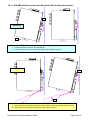
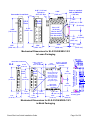
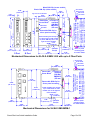
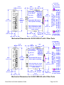
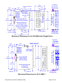
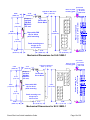
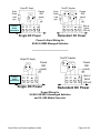
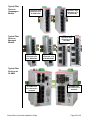
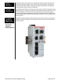
Slim Line (SL/SLX) Series
Industrial Ethernet Switches
& Media Converter
Installation Guide
Revision: 31 August 2009
http://www.sixnet.com
Table of Contents
Section 1
General Information
Page 4
Section 2
LED Indicators
Page 6
Section 3
Installation / Mounting
Page 8
Section 4
Power Wiring
Page 18
Section 5
Communication Wiring
Page 22
Section 6
Technical Specifications
Page 26
Section 7
Service Information
Page 30
This manual applies to the following products:
• SL-2ES-#
2-port unmanaged Ethernet media converter
• SL/SLX- 5ES-#
5-port unmanaged Ethernet switch with 5 10/100 ports
• SL/SLX- 5MS-#
5-port managed Ethernet switch with 5 10/100 ports
• SL/SLX-5MS-MDM-1
5-port managed Ethernet land-line modem with 5 10/100 ports
• SL/SLX- 6ES-#
6-port unmanaged Ethernet switch
• SL/SLX- 8ES/9ES-#
8/9-port unmanaged Ethernet switch with 8 or 9 10/100 ports
• SL/SLX- 8MS-#
8-port managed Ethernet switch with 8 10/100 ports
• SL/SLX- 8MG-1
8-port managed Ethernet switch with 8 Gigabit ports
• SLX-10MG-1
10-port managed Gigabit Ethernet switch with 10 ports
• SLX-16MS-1
16-port managed Ethernet switch with 16 10/100 ports
• SLX-18MG-1
18-port managed Gigabit Ethernet switch with 18 ports
To obtain support for Sixnet products:
Latest product info: http://www.sixnet.com
E-mail: mailto: [email protected]
Phone: +1 (518) 877-5173
Fax: +1 (518) 877-8346
Mailing address:
Sixnet Technology Park, 331 Ushers Road, Ballston Lake, NY 12019
Sixnet Slim Line Switch Installation Guide
Page 2 of 30
SIXNET Protected Technology Policy - Sixnet protects your investment in Sixnet systems with longterm planned technology and our unique Protected Technology Policy. We will continue to support the
specified capabilities of standard Sixnet products for at least five years (twenty years for Industrial Managed
Switches). We plan each product improvement and new feature to be upward compatible with existing
designs and installations. Our goals are to make each new software release bring new power to your Sixnet
systems and have every existing feature, applications program and data file continue to work. We protect
your investment even further with a liberal five-year trade-in policy. Exchange standard products for
upgraded versions of the same product to take advantage of new features and improvements at any time
for five years. A prorated trade-in allowance will be given for your existing unit. Sixnet protects your longterm productivity with state-of-the-art planned technology and continued support.
Sixnet Statement of Limited Warranty - Sixnet, manufacturer of Sixnet products, warrants to Buyer
that products, except software, manufactured by Sixnet will be free from defects in material and
workmanship. Sixnet's obligation under this warranty will be limited to repairing or replacing, at Sixnet's
option, the defective parts within one year of the date of installation, or within 18 months of the date of
shipment from the point of manufacture, whichever is sooner. Products may be returned by Buyer only after
permission has been obtained from Sixnet. Buyer will prepay all freight charges to return any products to
the repair facility designated by Sixnet. This limited warranty does not cover losses or damages which occur
in shipment to or from Buyer or due to improper installation, maintenance, misuse, neglect or any cause
other than ordinary commercial or industrial applications. In particular, Sixnet makes no warranties
whatsoever with respect to implied warranties of merchantability or fitness for any particular purpose. All
such warranties are hereby expressly disclaimed. No oral or written information or advice given by Sixnet or
Sixnet’s representative shall create a warranty or in any way increase the scope of this warranty. This
limited warranty is in lieu of all other warranties whether oral or written, expressed or implied. Sixnet's
liability shall not exceed the price of the individual units, which are the basis of the claim. In no event shall
Sixnet be liable for any loss of profits, loss of use of facilities or equipment, or other indirect, incidental or
consequential damages.
INSTALLATION WARNINGS - These products should not be used to replace proper safety
interlocking. No software-based device (or any other solid-state device) should ever be designed to
be responsible for the maintenance of consequential equipment or personnel safety. In particular,
Sixnet disclaims any responsibility for damages, either direct or consequential, that result from the
use of this equipment in any application. All power, input and output (I/O) wiring must be in
accordance with Class I, Division 2 wiring methods and in accordance with the authority having
jurisdiction.
FCC Statement - This equipment has been tested and found to comply with the limits for a Class B digital
device, pursuant to Part 15 of the FCC Rules. These limits are designed to provide reasonable protection
against harmful interference in a residential installation. This equipment generates, uses and can radiate
radio frequency energy and, if not installed and used in accordance with the instructions, may cause
harmful interference to radio communications. However, there is no guarantee that interference will not
occur in a particular installation. If this equipment does cause harmful interference to radio or television
reception, which can be determined by turning the equipment off and on, the user is encouraged to try to
correct the interference by one or more of the following measures: Reorient or relocate the receiving
antenna; Increase the separation between the equipment and receiver; Connect the equipment into an
outlet on a circuit different from that to which the receiver is connected; Consult the dealer or an
experienced radio/TV technician for help.
Copyright & Trademarks - Copyright ©2008 Sixnet, LLC. All Rights Reserved.
Note: All information in this document is subject to change without notice.
Sixnet Slim Line Switch Installation Guide
Page 3 of 30
Section 1
Overview
General Information
This manual will help you install and maintain these industrial Ethernet switches.
Installation of these switches is very easy and they will begin to operate as soon as they
are powered up. For the unmanaged models (denoted by ES in their part number) there
are no user settings so they are truly plug and play. The managed models (denoted by MS
in their part number) will act as unmanaged switches until they are configured otherwise.
Refer to the managed switch software manual for configuration of advanced network
functionality.
Note: This manual only covers the installation and wiring of these switches. For
the managed models refer to the separate Software User Manuals for details on
configuring and using any of the management functions such as SNMP, RSTP,
IGMP, VLANs, security, port mirroring and much more.
Operation
Unlike an Ethernet hub that broadcasts all messages out all ports, these industrial Ethernet
switches will intelligently route Ethernet messages only out the appropriate port. The major
benefits of this are increased bandwidth and speed, reduction or elimination of message
collisions, and deterministic performance when tied with real-time systems.
These industrial Ethernet switches can support 10BaseT (10 Mbps), 100BaseT (100
Mbps) and 1000BaseT (100 Mbps) on their RJ45 ports (depending on the model). Each of
these ports will independently auto-sense the speed/duplex, mdi/mdix-crossover and
polarity allowing you to use straight, crossed or even mis-wired cables. Some models also
have one or more fiber optic ports for making noise immune connections up to 120 km.
Performance
Specifications
These general specifications apply to these industrial Ethernet switches. Refer to Section 7
for complete technical specifications.
Number of ports
Ethernet Switch Type
Ethernet Switch Mode
Ethernet Protocols
RJ45 Ports Speed
RJ45 Ports Operation
Fiber Optic Port Speed
Fiber Optic Type
Safety
Standards
2, 5, 6, 8, 9, 10, 16 or 18 Ethernet ports
Unmanaged (ES models) or managed (MS models)
Store and forward, wire-speed, non-blocking
All standard IEEE 802.3 protocols supported
10/100 or 10/100/1000 Mbps
Auto-negotiation, auto-mdi/mdix-crossover and auto-polarity
100 Mbps (SC or ST) or 1000 Mbps (SFP/LC)
Multimode, singlemode, long-haul or special application
These industrial Ethernet Switches meet the following standards plus others:
Note: Some ratings may be pending on newer models. Contact Sixnet for latest info.
Sixnet, LLC is an ISO9001:2000 certified company (FM 65232) since 1996. These devices
are design, developed and manufactured per an ISO9001 quality management system.
Electrical safety –
• CE per Low Voltage Directive and EN61010-1 (IEC1010)
• UL recognition per UL508 (UL File # E179490)
• CSA per C22.2/14 (cUL File # E179490)
See warnings below.
Install the Managed Switches in accordance with local and national electrical codes.
Sixnet Slim Line Switch Installation Guide
Page 4 of 30
Lightning Danger: Do not work on equipment during periods of lightning activity.
Do not connect a telephone line into one of the Ethernet RJ45 connectors.
EMC (emissions and immunity) –
• CE per the EMC directive, EN 55022 or IEC 61326-1 or EN 61000-6-2/4
• FCC part 15 and ICES 003; Class B. See FCC statement on previous page.
Marine, maritime and offshore –
These devices, when installed in an appropriately IP rated enclosure, comply with the ABS
standards which is similar to DNV No. 2.4 and equivalent Lloyds. See warning below.
For marine and maritime compliance, do not install this product within 5 meters of a
standard or a steering magnetic compass.
WEEE compliance –
These devices comply with the WEEE directive. Do not throw away these devices in the
standard trash. Contact Sixnet regarding proper disposal.
9RoHS
RoHS compliance –
These devices comply with the RoHS directive and are consider lead and other hazardous
substance free.
Hazardous Locations –
• CE per ATEX directive and EN50021/EN60079-15 (Zone 2);
EEx nA II T4 X (-40°c ≤ Ta ≤ +85°C)
• UL per UL1604 (Class I, Div. 2), Groups A,B,C,D (UL File # E192531)
• CSA per C22.2/213 (Class 1, Div. 2), Groups A,B,C,D (cUL File # E192531)
See warnings below.
WARNING
(EXPLOSION HAZARD)
SUBSTITUTION OF COMPONENTS MAY IMPAIR SUITABILITY FOR
CLASS 1, DIVISION 2 (ZONE 2).
WARNING
(EXPLOSION HAZARD)
WHEN IN HAZARDOUS LOCATIONS, DISCONNECT POWER BEFORE
REPLACING OR WIRING UNITS.
WARNING
(EXPLOSION HAZARD)
DO NOT DISCONNECT EQUIPMENT UNLESS POWER HAS BEEN
SWITCHED OFF OR THE AREA IS KNOWN TO BE NONHAZARDOUS.
WARNING
(EXPLOSION HAZARD)
IN HAZARDOUS OR POTENTIALLY HAZARDOUS LOCATIONS, DO
NOT SEPARATE ANY PART OF THE UNIT WHEN ENERGIZED. USE
THE UNIT FOR INTERNAL CONNECTIONS ONLY.
Sixnet Slim Line Switch Installation Guide
Page 5 of 30
Section 2
Overview
LED Indicators
All these industrial Ethernet switches have 1 or 2 communication LEDs for each port and a
power LED. The managed models also have an “OK” output LED, a status LED and dual
power LEDs. Refer to the sample pictures below for the location of these LEDs.
Typical LED Location (varies with model)
Status LED
Managed Models Only: The Status LED indicates the overall health of the switch. It is
normally ON solid indicating that no internal CPU or software problems are detected. It will
flash when loading firmware and briefly on power up or reset. Otherwise, if it is OFF or
flashing for an extended period of time then a problem is detected. In this case, please
contact Sixnet for support.
Power LED
On unmanaged models there is typically one power LED that is ON if either power input
(P1 or P2) has power applied to it. On the managed models (and some unmanaged
models) there are two Power LEDs that indicate if there is power applied to the respective
input.
ACT / LNK
LED
This is the Yellow LED on models with two LEDs per RJ45 port.
Indicates that there is a proper Ethernet connection (Link) between
ON (yellow) the port and another Ethernet device, but no communications activity
(not flashing)
is detected.
Indicates that there is a proper Ethernet connection (Link) between
ON (yellow) the
port and another Ethernet device, and that there is
(flashing)
communications activity.
OFF
Speed 10/100
LED
Indicates that there is not a proper Ethernet connection (Link)
between the port and another Ethernet device. Make sure the cable
has been plugged securely into the ports at both ends.
This is the Green LED on models with two LEDs per RJ45 port.
ON (green)
A 100 Mbps (100BaseT) connection is detected.
OFF
A 10 Mbps (10BaseT) connection is detected.
Sixnet Slim Line Switch Installation Guide
Page 6 of 30
ACT / LNK /
Speed LED
This is a bi-color (green and yellow or orange) LED on models with one LED per RJ45
port.
Indicates that there is a proper Ethernet connection (Link) between
ON Solid
the port and another Ethernet device, but no communications activity
(not flashing)
is detected.
Indicates that there is a proper Ethernet connection (Link) between
the port and another Ethernet device, and that there is
Flashing
communications activity.
On 10/100 ports, a 100 Mbps connection is detected.
Green
On 10/100/1000 ports, a 1000 Mbps connection is detected.
Yellow or
On 10/100 ports, a 10 Mbps connection is detected.
ON 10/100/100 ports, a 10 or 1000 Mbps connection is detected.
Orange
OFF
Indicates that there is not a proper Ethernet connection (Link)
between the port and another Ethernet device. Make sure the cable
has been plugged securely into the ports at both ends.
OK LED
Managed Models Mostly and Some Unmanaged Models: This LED indicates the status
of the power inputs. There is an output screw terminal that can be connected as shown in
the wiring diagram. The output voltage from the screw terminal marked ‘OK’ will be the
same as the applied switch input voltage. The output will be ON when both the PI and P2
terminals have power applied to them. It will be OFF if either input does not have power or
the switch software is not running.
From PLC
Input LED
5MS-MDM Models Only: This LED indicates status of the Discrete “From PLC” input on
the modem. There is an input screw terminal that can be connected as shown in the
diagram. When voltage is applied to the From PLC input the LED will be ON. When no
voltage is applied the LED will be OFF.
To PLC
Output LED
5MS-MDM Models Only: This LED can indicate Power Status or Modem Connection
status. There is an output screw terminal. That can be connected as shown in the wiring
diagram. . The output voltage from the screw terminal marked ‘OK’ will be the same as the
applied switch input voltage. In “OK output” mode the output will be ON when both P1 and
P2 terminals have power applied to them. It will be OFF if either input does not have power
or the switch software is not running. In “Carrier Detect” mode the output will be ON when
the CD LED is ON and will be OFF when the CD LED is OFF.
CD LED
5MS-MDM Models Only: The CD LED indicates when there is a carrier (successful
connection) established between the SL-5MS-MDM and another modem. When OFF the
connection is not established, and when ON the Carrier is established.
RD LED
5MS-MDM Models Only: The RD LED flashes when the SL-5MS-MDM is receiving data
from the phone line port. Flashing on this LED when the CD LED is OFF could indicate a
Ring coming in from a calling device. When the CD LED is ON and the RD LED is flashing
will indicate communication coming in from the remote device.
TD LED
5MS-MDM Models Only: The TD LED will flash on as the SL-5MS-MDM transmits data
out to the modem. The flashing of TD LED while the CD LED is ON will indicate
communications between the SL-5MS-MDM and device connected to the other modem.
Sixnet Slim Line Switch Installation Guide
Page 7 of 30
Section 3
Installation
These industrial Ethernet switches can be snapped onto a standard DIN rail (EN50022) or
screwed directly to a flat panel. Refer to the mechanical drawings below to properly mount
your switch.
Overview
Note: Make sure to allow enough room to route your Ethernet copper or fiber optic cables.
SL- or SLX-#ES models in Lexan case:
1
Mounting
2
Recommended DIN rail mounting steps:
1. Hook the top back of the unit over the DIN rail.
2. Push the bottom of the unit towards the DIN rail until it snaps into place.
B
Removal
A
Recommended DIN rail removal steps:
A. Insert screwdriver into DIN clip and pry until the bottom of the unit releases from the din rail.
B. Unhook the top of the unit and remove it from the DIN rail.
Sixnet Slim Line Switch Installation Guide
Page 8 of 30
SL- or SLX-#ES models in metal case:
1
Mounting
2
Recommended DIN rail mounting steps:
1. Hook the top back of the DIN rail clip on the unit over the din rail.
2. Push the bottom of the unit towards the DIN rail until it snaps into place.
C
A
Removal
B
Recommended DIN rail removal steps:
A. Push the whole unit down to free the bottom of the DIN rail clip. See blue circle area.
B. Pull the bottom of the unit away from the DIN rail.
C. Unhook the top of unit and remove it from the DIN rail.
Sixnet Slim Line Switch Installation Guide
Page 9 of 30
SL- or SLX-#MS models in metal case with plastic DIN rail clip (older models):
1
Mounting
2
Recommended DIN rail mounting steps:
1. Hook the top back of the unit over the DIN rail.
2. Push the bottom of the unit towards the DIN rail until it snaps into place.
Removal
B
A
Recommended DIN rail removal steps:
A. Insert screwdriver into DIN clip and pry until the bottom of the unit releases from the din rail.
B. Unhook the top of the DIN clip and remove the unit from DIN rail.
Sixnet Slim Line Switch Installation Guide
Page 10 of 30
SL/SLX-#MS and -#MG models in metal case with metal DIN rail clip:
1
Mounting
2
Recommended DIN rail mounting steps:
1. Hook the top back of the DIN rail clip on the unit over the din rail.
2. Push the bottom of the unit towards the DIN rail until it snaps into place.
C
A
Removal
B
Recommended DIN rail removal steps:
A. Push the whole unit down to free the bottom of the DIN rail clip. See blue circle area.
B. Pull the bottom of the unit away from the DIN rail.
C. Unhook the top of unit and remove it from the DIN rail.
Sixnet Slim Line Switch Installation Guide
Page 11 of 30
0.40" (1.02 cm)
Typical for
SC or ST fiber
Removable Screw Block
1.01"
[2.57 cm]
6/8/9
Ports
2/3/5
Ports
3.95"
[10.03 cm]
Snaps to standard
DIN rail EN50022
(35 mm)
2.90"
[7.35 cm]
1.98"
[5.02 cm]
Dia. 0.15"
(0.38 cm)
Use for direct
panel mounting
to a flat surface
4.20"
[10.67 cm]
1.98"
[5.02 cm]
1.01"
[2.57 cm]
3.26"
[8.28 cm]
1.50"
[3.81 cm]
1.00"
[2.54 cm]
0.06"
[0.15 cm]
Mechanical Dimensions for SL-2/3/5/6/8/9ES-1/2/3
in Lexan Packaging
SLX
0.175"
[0.44 cm]
2/3/5
Ports
4.50"
[11.43 cm]
0.40" (1.02 cm)
Typical for
SC or ST fiber
6/8/9
Ports
4.00"
[10.16 cm]
4.35"
[11.05 cm]
0.30"
[0.76 cm]
Snaps to standard
DIN rail EN50022
(35 mm)
Use for direct panel
mounting to a flat
surface with up to
#8 screw for older
units or up to #12
for newer units
(see guide to right)
Removable
for direct panel
mounting
0.55"
[1.40 cm]
1.10"
[2.79 cm]
1.60"
[4.06 cm]
0.80"
[2.03 cm]
1.50"
[3.81 cm]
3.00"
[7.62 cm]
2.25"
[5.71 cm]
C
2.25"
[5.71 cm]
0.39"
[0.99 cm]
Panel mounting ears on
newer models accept
up to a #12 screw
Removable Screw Block
Direct to panel
mounting guide
Mechanical Dimensions for SLX-2/3/5/6/8/9ES-1/2/3
in Metal Packaging
Sixnet Slim Line Switch Installation Guide
Page 12 of 30
Metal DIN Clip (newer models)
Plastic DIN Clip (older models)
Removable DIN clip for
direct panel mounting
Panel mounting ears accept up
to a #6 screw on older models
w/ plastic DIN clip (see to the
right for newer models)
0.15"
[0.38 cm]
Console
Port(s)
1.90"
[4.83 cm]
1.60"
[4.07 cm]
C
0.39"
[0.99 cm]
cm]
cm]
cm]
cm]
Direct to panel
mounting guide
for newer models
0.43"
3.82"
[12.83
[12.95
[13.08
[13.21
5.05"
[12.83 cm]
ST Fiber
For #6 screw: 5.05"
For #8 screw: 5.10"
For #10 screw: 5.15"
For #12 screw: 5.20"
SC Fiber
Snaps to
standard
DIN Rail
EN50022
(35 mm)
Panel mounting ears on
newer models (w/ metal DIN clip)
accept up to a #12 screw
5.20"
[13.21 cm]
Removable
Screw Block
4.70"
[11.94 cm]
1.07"
[2.71 cm]
1.92"
[4.88 cm]
2.60"
[6.60 cm]
Typ. for SC or ST Fiber
0.40"
[1.02 cm]
0.51"
[1.29 cm]
#12 screw
#10 screw
#8 screw
#6 screw
0.53"
[1.36 cm]
2.60"
[6.60 cm]
0.80"
[2.04 cm]
5 Port
8 Port
[9.70 cm]
[1.10 cm]
Mechanical Dimensions for SL/SLX-5/8MS-1/4/5 with up to 2 Fiber Ports
4.70"
[11.93 cm]
5.20"
[13.21 cm]
5.05"
[12.83 cm]
Removable DIN clip for
direct panel mounting
Panel mounting ears accept
up to a #6 screw on older
models (see to the right for
newer models)
0.15"
[0.38 cm]
1.90"
[4.83 cm]
1.00"
[2.54 cm]
2.00"
[5.08 cm]
Snaps to
standard
DIN Rail
EN50022
(35 mm)
2.60"
[6.60 cm]
C
2.60"
[6.60 cm]
Console
Port(s)
3.82"
[9.70 cm]
0.39"
[0.99 cm]
cm]
cm]
cm]
cm]
Removable
Screw Block
For #6 screw: 5.05" [12.83
For #8 screw: 5.10" [12.95
For #10 screw: 5.15" [13.08
For #12 screw: 5.20" [13.21
1.92"
[4.88 cm]
Panel mounting ears on
newer models accept
up to a #12 screw
#12 screw
#10 screw
#8 screw
#6 screw
Direct to panel
mounting guide
for newer models
Mechanical Dimensions for SL/SLX-5MS-MDM-1
Sixnet Slim Line Switch Installation Guide
Page 13 of 30
SC Fiber
ST Fiber
5.05"
[12.83 cm]
for #6
screw
5.20"
[13.21 cm]
Snaps to
standard
DIN Rail
EN50022
(35 mm)
Removable DIN clip for
direct panel mounting
Panel mounting ears accept
up to a #6 screw on older
models (see to the right for
newer models)
1.90"
[4.83 cm]
0.80"
[2.04 cm]
1.60"
[4.07 cm]
2.60"
[6.60 cm]
Console
Port(s)
3.82"
[9.70 cm]
2.60"
[6.60 cm]
0.39"
[0.99 cm]
cm]
cm]
cm]
cm]
Removable
Screw Block
1.92"
[4.88 cm]
For #6 screw: 5.05" [12.83
For #8 screw: 5.10" [12.95
For #10 screw: 5.15" [13.08
For #12 screw: 5.20" [13.21
0.40"
[1.02 cm]
typical
Panel mounting ears on
newer models accept
up to a #12 screw
0.15"
[0.38 cm]
#12 screw
#10 screw
#8 screw
#6 screw
Direct to panel
mounting guide
for newer models
Mechanical Dimensions for SL/SLX-8ES-6/7 with 3 Fiber Ports
SC Fiber
ST Fiber
5.05"
[12.83 cm]
for #6
screw
5.20"
[13.21 cm]
Removable DIN clip for
direct panel mounting
Panel mounting ears accept
up to a #6 screw on older
models (see to the right for
newer models)
1.90"
[4.83 cm]
0.80"
[2.04 cm]
1.60"
[4.07 cm]
2.60"
[6.60 cm]
Console
Port(s)
3.82"
[9.70 cm]
2.60"
[6.60 cm]
0.39"
[0.99 cm]
cm]
cm]
cm]
cm]
Snaps to
standard
DIN Rail
EN50022
(35 mm)
[12.83
[12.95
[13.08
[13.21
Removable
Screw Block
1.92"
[4.88 cm]
For #6 screw: 5.05"
For #8 screw: 5.10"
For #10 screw: 5.15"
For #12 screw: 5.20"
0.40"
[1.02 cm]
typical
Panel mounting ears on
newer models accept
up to a #12 screw
0.15"
[0.38 cm]
#12 screw
#10 screw
#8 screw
#6 screw
Direct to panel
mounting guide
for newer models
Mechanical Dimensions for SL/SLX-8MS-8/9 with 4 Fiber Ports
Sixnet Slim Line Switch Installation Guide
Page 14 of 30
5.20"
[13.21 cm]
2.60"
[6.60 cm]
0.35"
[0.88 cm]
5.05"
[12.83 cm]
Console
Ports
Panel mounting ears
accept up to a #6
screw on earlier models
and up to a #12 screw
on newer models.
4.70"
[11.94 cm]
0.15"
[0.38 cm]
1.88"
[4.78 cm]
3.80"
[9.65 cm]
cm]
cm]
cm]
cm]
Removable
Snaps to
Screw
Block
standard
DIN Rail
SFP Fiber
EN50022
Ports
(35 mm)
Removable DIN clip
for direct panel mounting
[12.83
[12.95
[13.08
[13.21
Typical for SFP Xcvrs
0.50"
[1.27 cm]
For #6 screw: 5.05"
For #8 screw: 5.10"
For #10 screw: 5.15"
For #12 screw: 5.20"
2.60"
[6.60 cm]
1.92"
[4.88 cm]
Panel mounting ears on
newer models
accept up to a #12 screw
0.39"
[0.99 cm]
#12 screw
#10 screw
#8 screw
#6 screw
2.75"
[6.98 cm]
1.37"
[3.49 cm]
Direct to panel
mounting guide
for newer models
Mechanical Dimensions for SL/SLX-8MG with 8 Gigabit Ports
2.76"
[7.01 cm]
5.52"
[14.02 cm]
2.76"
[7.01 cm]
Typical for SFP Xcvrs
0.50" [1.27 cm]
2.15"
[5.46 cm]
Snaps to
standard
DIN Rail
EN50022
(35 mm)
Removable
Screw Block
Removable DIN
clip for direct
panel mounting
Panel mounting ears
accept up to a #12 screw
0.39"
[0.99 cm]
#12 screw
#10 screw
#8 screw
#6 screw
6.02"
[15.29 cm]
Panel mounting ears
accept up to
a #12 screw
0.35"
[0.88 cm]
2.15"
[5.46 cm]
1.63"
[4.13 cm]
Direct to panel
mounting guide
Mechanical Dimensions for SLX-10MG-1
Sixnet Slim Line Switch Installation Guide
Page 15 of 30
2.76"
[7.01 cm]
5.52"
[14.02 cm]
2.76"
[7.01 cm]
Typical for SFP Xcvrs
0.50" [1.27 cm]
2.15"
[5.46 cm]
Snaps to
standard
DIN Rail
EN50022
(35 mm)
Removable
Screw Block
Panel mounting ears
accept up to a #12 screw
0.39"
[0.99 cm]
#12 screw
#10 screw
Direct to panel
#8 screw
mounting guide
#6 screw
6.02"
[15.29 cm]
Removable DIN
clip for direct
panel mounting
Panel mounting ears
accept up to
a #12 screw
0.35"
[0.88 cm]
2.13"
[5.40 cm]
2.15"
[5.46 cm]
Mechanical Dimensions for SLX-16MS-1
2.76"
[7.01 cm]
5.52"
[14.02 cm]
2.76"
[7.01 cm]
0.35"
[0.88 cm]
Typical for SFP Xcvrs
0.50" [1.27 cm]
2.15"
[5.46 cm]
Snaps to
standard
DIN Rail
EN50022
(35 mm)
Removable
Screw Block
Removable DIN
clip for direct
panel mounting
6.02"
[15.29 cm]
Panel mounting ears
accept up to
a #12 screw
2.15"
[5.46 cm]
#12 screw
#10 screw
#8 screw
#6 screw
Panel mounting ears
accept up to a #12 screw
0.39"
[0.99 cm]
Direct to panel
mounting guide
2.88"
[7.31 cm]
Mechanical Dimensions for SLX-18MG-1
Sixnet Slim Line Switch Installation Guide
Page 16 of 30
The metal packaged models allow you to choose the mounting method that best fits your requirements. (Note:
Not all methods are available on all models. Refer to the mechanical diagrams for details.)
Vertical snap-on DIN rail
mounting for quickest
installation and optimal
utilization of your rail space.
Vertical screw-topanel mounting for
better shock and
vibration resistance.
Flat screw-to-panel mounting
for low profile orientation
in shallow boxes plus best
shock and vibration resistance.
Overview of Optional Mounting Methods
Important Notes about
Thermal Performance:
The Slim Lines switches with metal cases use
an innovative technique to remove excess
heat from the product and its components.
This technique effectively utilizes the heavygauge all-aluminum case as a large heat-sink.
Therefore, you may notice the case becoming
warm during operation (especially with large
loads such as all ports linked and active). This
is normal operation. For best performance it is
recommended that a DIN rail spacer (such as
an end clamp) be used between the switch
and adjacent devices. This will leave an air
gap for best heat dissipation off the case.
Also, do not block the air slots.
For best thermal performance when direct
panel mounting to a metal surface, you may
use a thermal compound or pad between the
mounting face and the mounting surface. This
will reduce any air gaps and optimize the
transfer of heat from the case to the mounting
surface.
Notes and Recommendations for Best Heat Dissipation
Sixnet Slim Line Switch Installation Guide
Page 17 of 30
Section 4
Overview
Power and Output Wiring
These industrial Ethernet switches can be powered from the same DC source that is used
to power your other devices. A voltage in the range of 10 to 30 VDC needs to be applied
between the P1 (plus) terminal and the Minus terminal as shown in the diagrams on the
next page. The chassis screw terminal should be tied to panel or chassis ground. To
reduce down time resulting from power loss, these industrial Ethernet switches can
optionally be powered redundantly with a second power supply as shown in the diagrams.
The managed models also have an “OK” output that can be tied to a PLC input or other
device to indicate when there is a power loss. When ON, this output will source the same
voltage that is applied to the switches power terminals. See the wiring diagrams on the
next page.
Screw Torque
WIRING
WARNINGS
When tightening the screws be careful to tighten to a max. torque of 5 in/lb (0.57 Nm).
BEFORE PERFORMING ANY WIRING TO THESE SWITCHES MAKE SURE …
• THE AREA IS CURRENTLY NONHAZARDOUS (ESPECIALLY WHEN
WORKING IN CLASS I, DIV 2 OR ZONE 2 HAZARDOUS LOCATIONS)
• TO TURN OFF THE POWER TO THE SWITCH
• TO UNPLUG THE SCREW TERMINAL BLOCK (This is especially important on
the units that have a metal case as shown below. Connecting or disconnecting
wires to the screw block when it is in place and the power is turned on can
allow the screwdriver to short the power to the case.)
TO PREVENT
SHORTING THE
POWER TO THE
CASE ALWAYS
UNPLUG THE
SCREW
TERMINAL
BLOCK BEFORE
PERFORMING
ANY WIRING!
UL Requirements
To meet the requirements for UL you must do one of the following:
1. Install a 3.33 Amp maximum fuse at the input of the switch.
OR
2. Use a Class 2 rated power supply to power the switch.
Sixnet Slim Line Switch Installation Guide
Page 18 of 30
Dual DC Supplies
Single DC Supply
Chassis
GND
(panel)
+
-
Frontofof
Front
Switch
Switch
(connectors)
(connectors)
Alarm
Output
Load
(opt.)
Chassis
GND
(panel)
+
-
Alarm
Output
Load
(opt.)
OK P2 P1
OK P2 P1
Single DC Power
Back of
Switch
(DIN rail)
Redundant DC Power
Power & Alarm Wiring for
SL/SLX-5/8MS Managed Switches
-------------------------------------------------------
Dual DC Supplies
Single DC Supply
Chassis
GND
(panel)
Front
of
Front of
Switch
Switch
(connectors)
(connectors)
Chassis
GND
(panel)
P2 P1
P2 P1
Single DC Power
Back of
Switch
(DIN rail)
Redundant DC Power
Power Wiring for
SL/SLX-5/8/9ES Unmanaged Switches
and SL-2ES Media Converter
Sixnet Slim Line Switch Installation Guide
Page 19 of 30
Single DC Supply
Chassis
GND
(panel)
PLC or
Other
Device
IN
Frontofof
Front
Switch
Switch
(connectors)
(connectors)
Dual DC Supplies
Chassis
GND
(panel)
PLC or
Other
Device
IN
OUT
OUT
From To P2
PLC PLC +
P1
+
From To P2
PLC PLC +
P1
+
IN OUT IN
IN
IN OUT IN
IN
Single DC Power
Back of
Switch
(DIN rail)
Redundant DC Power
Power & PLC Wiring for
SL/SLX-5MS-MDM Ethernet Modem
-------------------------------------------------------
One DC Supply
+ -
(optional)
Back of
Switch
(DIN rail)
Chassis
GND
(panel)
(optional)
P1 P2 OK
P1 P2 OK
Single DC Power
Alarm
Output
Load
+ -
Alarm
Output
Load
+ -
Chassis
GND
(panel)
Dual DC Supplies
Front
Frontofof
Switch
Switch
(connectors)
(connectors)
Redundant DC Power
Power & Alarm Wiring for
SL/SLX-8MG Managed Switches
Sixnet Slim Line Switch Installation Guide
Page 20 of 30
+
Front
of
Front of
Switch
Switch
(connectors)
(connectors)
P2 P1
Dual DC Supplies
Alarm
Output
Load
(opt.)
Chassis GND is
made through the
DIN rail mounting
OK
Alarm
Output
Load
(opt.)
+
-
Single DC Supply
Single DC Power
P2 P1
OK
Back of
Switch
(DIN rail)
Redundant DC Power
Power and Alarm Wiring For
SL/SLX-6ES Unmanaged Switches
-------------------------------------------------------
Dual DC Supplies
+ -
Alarm
Output
Load
(opt.)
+ -
Back of
Switch
(DIN rail)
OK
Chassis
GND
(panel)
P2 P1
Single DC Power
+ -
Single DC Supply
Alarm
Output
Load
(opt.)
OK
P2 P1
Chassis
GND
(panel)
Front
of of
Front
Switch
Switch
(connectors)
(connectors)
Redundant DC Power
Power and Alarm Wiring for
SLX-10/16/18-Mx Managed Switches
Sixnet Slim Line Switch Installation Guide
Page 21 of 30
Section 5
Communication Ports Wiring
Overview
These industrial Ethernet switches provide connections to standard Ethernet devices such
as PLCs, Ethernet I/O, industrial computers and much more. Three types of
communication ports may be found on these switches: RJ45 (copper) Ethernet ports, fiber
optic Ethernet ports and a serial or USB console port for management (managed models).
RJ45
Ethernet
Wiring
Use data-quality (not voice-quality) twisted pair cable rated category 5 (or better) with
standard RJ45 connectors. For best performance use shielded cable. Straight through or
crossover RJ45 cable can be used regardless of the device the switch is to be connected
to as all the ports are capable of auto-mdi/mdix-crossover detection.
The RJ45 Ethernet port connector bodies on these products are metallic and are
connected to the Chassis GND terminal. Therefore, shielded cables may be used to
provide further protection. To prevent ground loops, the cable shield should be tied to the
metal connector body at one end of the cable only. Electrical isolation is also provided on
the Ethernet ports for increased reliability.
For Reference
Only.
Either cable
wiring will work!
Straight-thru Cable Wiring
Pin 1
Pin 1
Pin 2
Pin 2
Pin 3
Pin 3
Pin 6
Pin 6
Cross-over Cable Wiring
Pin 1
Pin 3
Pin 2
Pin 6
Pin 3
Pin 1
Pin 6
Pin 2
Ethernet
Plug & Connector
Pin Positions
RJ45 Cable
Distance
The maximum cable length for 10/100/1000BaseT is typically 100 meters (328 ft.).
Ethernet
Fiber Wiring
Guidelines
Depending on the model these industrial Ethernet switches may have up to four fiber optic
ports. All 100 Mbps fiber ports are available with dual SC or ST style connectors. They are
also available with multimode, singlemode, long-haul (for connections up to 120+ km) or
special-application transceivers. Refer to the technical specifications for details.
All 1000 Mbps fiber ports are provided as mini-gbic SFP (small form pluggable). These
accept plug in fiber transceivers that typically have an LC style connector. They are
available with multimode, singlemode, long-haul (for connections up to 80+ km) or specialapplication transceivers. Refer to the technical specifications for details.
For each fiber port there is a transmit (TX) and receive (RX) signal. When making your
fiber optic connections, make sure that the transmit (TX) port of the switch connects to the
receive (RX) port of the other device, and the receive (RX) port of the switch connects to
the transmit (TX) port of the other device.
Use standard fiber optic wiring techniques (not covered by this manual) to make your
connections. The corresponding ACT/LNK LED will be ON solid or flashing when you have
made a proper connection.
For more fiber optic guidelines go to: http://www.sixnet.com
See images below for typical fiber optic port placement on these switches.
Sixnet Slim Line Switch Installation Guide
Page 22 of 30
Typical Fiber
Ports on
Unmanaged
Models
Typical SC style
connector on a
SL-5ES-2/3SC
Typical ST style
connector on a
SL-5ES-2/3ST
Typical Fiber
Ports on
Managed
Models
Typical SC style
connector on a
SLX-8xS-
Typical SC style
connector on a
SLX-5MS-4/5SC
Typical ST style
connector on a
SLX-5MS-4/5ST
Typical Fiber
Ports on an
SL-8MG
SLX-8MG with
no transceivers
installed
Sixnet Slim Line Switch Installation Guide
SLX-8MG with
four transceivers
installed
Page 23 of 30
Duplex
Operation
The RJ45 ports will auto-sense for Full or Half duplex operation, while the fiber ports are
configured for full duplex operation. Note: Fiber devices with half duplex settings should
still communicate with the switch. If otherwise then please contact Sixnet. On managed
models the duplex setting is software configurable.
Verifying
Connectivity
After all Ethernet and/or fiber connections are made, check the LED’s corresponding to the
ports that each of the devices are connected to. Ensure that for each port that is in use, the
LED is on or blinking. If a port LED is off, go back and check for connectivity problems
between that port and the network device connected to that particular port. In addition, the
color of the LED should indicate the speed for which your device is connected at (see prior
section on LEDs).
Telephone
Port Wiring
A standard cross-wired telephone patch cable should be used to connect to the phone line
provided by the phone company. Tip and Ring are the only two pins used on the Ethernet
Land-Line modem.
(MDM models)
Telephone
Ports on
Modem Models
Sixnet Slim Line Switch Installation Guide
Page 24 of 30
Serial
Console Port
Wiring
An optional way to configure the switch is through the RJ45 console RS232 port. Use a
DB9F to RJ45F adapter along with a RJ45 male to RJ45 male straight-thru-wired patch
cable to make a connection between a com port on your PC (DB9 male) and the RS232
port of the Managed Switch (RJ45 female). Contact Sixnet or your switch vendor to
purchase this adapter as an accessory.
A typical DB9F to RJ45F adapter should be wired as follows:
RJ45F
Pin #
1
2
3
4
5
6
7
8
USB Console
Port Wiring
Switch
Signal
Name
RI/DSR in
DCD in
DTR out
GND
RXD in
TXD out
CTS in
RTS out
Adapter
Signal
DB9F
Name
Pin #
DTR out
4
N/C
n/c
DSR in
6
GND
5
TXD out
3
RXD in
2
RTS out
7
CTS in
8
Newer models of these switches may also have an USB port instead of or in addition to the
RS232 port. Use a standard USB cable with a mini-USB plug on one end and an A-typeUSB plug on the other end. The A-type plug goes into a standard USB port on a computer.
The mini-USB plug goes into the USB port on the switch.
Refer to the software user manual for how to use this USB port.
RS232
RJ45F
RS232
RJ45F
Mini-USB
Mini-USB
The RS232 and/or USB ports may located
on the bottom edge or front face of the switch
Sixnet Slim Line Switch Installation Guide
Page 25 of 30
Section 6
Technical
Specs
Technical Specifications
Here are the hardware technical specifications for the industrial Ethernet switches covered
by this manual. For the managed models, refer to the software user manual or datasheet
for complete software specifications.
Note: These specifications are subject to change. Contact Sixnet for the latest details.
General Specifications:
Ethernet switch type
Operating mode
Devices supported
Protocols
(managed models only)
Industrial protocols
supported
Standards (depends on
model)
Management interfaces
(managed models only)
Open source linux
(managed models only)
MAC addresses
Memory bandwidth
Latency for 10 Mbps
Latency for 100/1000 Mbps
Ethernet isolation
Management serial port
(managed models only)
Unmanaged or managed with up to 9 ports
Store and forward, wire-speed switching, non-blocking
All IEEE 802.3 compliant devices are supported
SNMPv1/v2/v3, RMON, DHCP, SNTP, TFTP, STP, RSTP,
QoS/CoS/ToS/DS, IGMPv1/v2, VLAN (tag and port based), HTTP,
HTTPS (SSL & TSL), Telnet, SSH and more
Modbus/TCP, EtherNet/IP, PROFInet, Foundation Fieldbus HSE
and others
IEEE 802.3, 802.3u, 802.3ab/z, 802.3x, 802.1D/w, 802.1p, 802.1Q
and others
Web (see online demo), text (Telnet & SSH), CLI (command line
interface) and SNMP (see software manual for supported MIBs)
The Linux Advantage – Contact Sixnet for more information
1024 on unmanaged (ES) models;
2048 on managed (MS)models;
8192 on Gigabit (MG) models
3.2 Gbps on ES & MS models; 32 Gbps on MG models
16 us + frame time (typical)
Varies on load and settings
<5 us + frame time (typical)
1500 VRMS 1 minute
RS232 (TXD, RXD and GND), 9600, 8, N, 1 fixed
and/or mini-USB
Copper RJ45 Ports: (10/100 Mbps or 10/100/1000 Mbps)
Copper ports
Speed
Protocols supported
Auto-crossover
Auto-sensing operation
Auto-negotiating
Auto-polarity
Flow control
Ethernet isolation
Plug and play
Cable requirements
Max. cable distance
Shielded RJ45
10/100 Mbps or 10/100/1000 Mbps (depending on model)
All standard IEEE 802.3
Yes, allows you to use straight or cross wired cables
Yes, Full and half duplex
Yes, 10BaseT and 100BaseT
Yes, on the TD and RD pair
Automatic
1500 VRMS 1 minute
Yes
Twisted pair (Cat. 5 or better) (shielded recommended)
100 meters
Sixnet Slim Line Switch Installation Guide
Page 26 of 30
SC or ST Fiber Ports: (100BaseF multimode or singlemode)
100BaseF ports
Fiber port mode
Fiber port connector
Optimal fiber cable
Center wavelength
Multimode
Singlemode
Singlemode long haul
Nominal max. distance (full
duplex)
(see web for details)
Half and full duplex
Ethernet compliance
Eye safety
Up to 4
Multimode (mm) or Singlemode (sm)
Duplex SC or ST
50/125 or 62.5/125 µm for mm; 9/125 µm for sm
1300 nm (other wavelengths available)
Links up to 4 km typ.; 1310 nm; use with 50 or 62.5/125 um fiber
> Transmitter power (dB): -21 min, -17 typ, -14 max
> Receiver sensitivity (dB): -34 typ, -31 max
Links up to 20 km typical; 1310 nm; use with 9/125 um fiber
> Transmitter power (dB): -15 min, -11 typ, -8 max
> Receiver sensitivity (dB): -36 typ, -31 max
Links up to 40 km typical; 1310 nm; use with 9/125 um fiber
> Transmitter power (dB): -5 min, -3 typ, -0 max
> Receiver sensitivity (dB): -36 typ, -34 max
4 km with multimode;
20 km with singlemode;
up to 120 km with long haul singlemode
Full duplex on unmanaged models;
Software configurable on managed models
100BaseF
IEC 60825-1, Class 1; FDA 21 CFR 1040.10 and 1040.11
SFP Mini-Gbic SFP (pluggable) Ports: (many types available)
Note: On the Gigabit (MG) models these ports are pluggable and accept many different types of
pluggable SFP (Mini-Gbic) transceiver modules for Gigabit fiber connections.
Gigabit SFP ports
Up to 4
Port types supported
Gigabit fiber multimode, fiber singlemode, fiber long-haul
singlemode, fiber single-strand and more
Note: 100 Mbps fiber transceiver modules are also supported on these ports.
Fiber port connector
LC typically for fiber (depends on module)
Optimal fiber cable
Typical 50 or 62.5/125 µm for multimode (mm);
Typical 8 or 9/125 µm for singlemode (sm)
Fiber wavelength (typical)
850 nm for mm; 1310 nm for sm; 1550 for long haul sm
TX output power
See fiber transceiver datasheet for details.
RX input sensitivity
Max. distance (full duplex)
Up to 80+ km with long haul singlemode modules
Half and full duplex
Software Configurable
Ethernet compliance
1000BaseT and 1000BaseF (SX/LX/LH)
Eye safety
IEC 60825-1, Class 1; FDA 21 CFR 1040.10 and 1040.11
Note: See SFP fiber optic transceiver datasheet for complete
specifications. Also, other fiber transceivers may be available for
special requirements such as longer distances, single strand (BiDi) or
other special applications. Contact Sixnet for details.
Sixnet Slim Line Switch Installation Guide
Page 27 of 30
Industrial Telephone Modem (SL-5MS-MDM Only)
Maximum data rates
Compatibility
Data compression
Error correction
Ringer
Jacks
Command sets
Country compatibility
Telecom ratings
56 Kbps
V.90, V.34, V.32, V.32 bis, V.22, V.22 bis, V.21
V.42 bis
V.42 MNP or LAP
0.3
2 RJ11 (phone and line)
Standard AT and S register
World-wide (100+ countries)
FCC Part 68; Industry Canada CS03-8; CTR21 (98/482/EC); ACA TS
001 and ACA TS 002
“PLC” Input and Output (SL-5MS-MDM Only)
PLC / Alarm output voltage
Maximum current output
PLC / Trigger input voltage
Typically current input
Same as switch input power voltage
0.5 Amp
10-30 VDC
6.5 mA @ 24 VDC
“OK” Alarm Output (managed models only)
“OK” Output
Voltage
Maximum current output
ON if P1 and P2 have power and switch software is running
Same as switch input voltage
0.5 Amp
Power Input:
Power input
Input power (typical with
all ports active at 100
Mbps)
Redundant Input Terminals
2.0 W (2-port converter with 1 fiber),
2.0 W (5-port unmanaged w/ 0 fiber),
3.0 W (5-port unmanaged w/ 1 fiber),
5.0 W (6-port unmanaged w/ 2 fiber),
4.0 W (8-port unmanaged w/ 0 fiber),
5.0 W (9-port unmanaged w/ 1 fiber),
8.0 W (8-port unmanaged w/ 3 fiber)
Input voltage (all models)
Reverse power protection
Transient protection
Spike protection
Sixnet Slim Line Switch Installation Guide
3.6 W (5-port managed w/o fiber),
4.8 W (5-port with phone modem),
5.6 W (5-port managed w/ 2 fiber),
4.3 W (8-port managed w/ 0 fiber),
6.3 W (8-port managed w/ 2 fiber),
9.0 W (8-port managed w/ 4 fiber),
12 W (8-port man. gigabit w/ 0 fiber)
15 W (8-port man. gigabit w/ 4 fiber),
5.0 W (10-port man. gigabit w/ 0 fiber),
7.0 W (10-port man. gigabit w/ 2 fiber),
7.0 W (16-port man. gigabit w/ 0 fiber),
8.0 W (18-port man. gigabit w/ 0 fiber),
10 W (18-port man. gigabit w/ 2 fiber)
10-30 VDC (continuous)
Yes
15,000 watts peak
5,000 watts (10x for 10 uS)
Page 28 of 30
Environmental and Compliances:
Operating temperature
range
SL-2/5/6/8/9ES models: -10 to +60°C (cold startup at -10°C)
SL-5/8MS models: -10 to +60°C (cold startup at -10°C)
SL/SLX-5MS-MDM: -40 to +75°C (cold startup at -40°C)
SL/SLX-8MG: -40 to +75°C (cold startup at -40°C)
SLX-5/6/8/9ES-1/2/3/4/5 models: -40 to +85°C (cold startup at -40°C)
SLX-8ES-6/7 models: -40 to 75° C (cold startup at -40°C)
SLX-5/8MS models: -40 to +75°C (cold startup at -40°C)
SLX-10/18MG-1 model -40 to +75°C (cold startup at -40°C)
SLX-16MS-1 model -40 to +75°C (cold startup at -40°C)
Storage temperature range
Humidity (non-condensing)
Vibration, shock & freefall
Electrical safety
EMC: emissions and
immunity
Hazardous Locations
Eye safety (fiber models)
MTBF
RoHS and WEEE
ISO9001:2000
Contact Sixnet if wider ranges are needed.
-40 to +85 °C
5 to 95% RH
Contact Sixnet for optional conformal coating.
IEC68-2-6, -27, -32
UL508/CSA C22, EN61010-1, CE
FCC part 15, ICES-003;
EN55022 and/or IEC61326-1 and/or EN61000-6-2/4
UL1604, CSA C22.2/213 (Class I, Div.2) ;
EN50021/EN60079-15 (Zone2), CE (ATEX)
IEC60825-1, Class 1; FDA 21 CFR
1040.10 and 1040.11
Mean Time Between Failure: >1,000,000 hours typical
per MIL-HDBK-217F2 Ground Benign at 35˚C
RoHS (Pb free) and WEEE compliant
Certified “Total Quality” company
Mechanical:
Ingress protection
Packaging and protection
Dimensions (L x W x H)
Weights (typical)
IP30 (all models)
UL94V0 Lexan plastic for all plastic cased units.
Aluminum w/ protective finish for all metal cased units.
See mechanical diagrams for details
SL-2ES-2/3 and SL-5ES-1/2/3 in Lexan case – 4 oz (0.11 kg)
SLX-5ES-1/2/3 in metal case – 6 oz (0.11 kg)
SL/SLX-5MS-1/4/5 in metal case – 8 oz (0.23 kg)
SL-5MS-MDM managed – 11 oz (0.31 kg)
SL-6/8/9ES-1/2/3/4/5 in Lexan case – 6 oz (0.17 kg)
SLX-6/8/9ES-1/2/3/4/5 in metal case – 8 oz (0.23 kg)
SL/SLX-8MS-1/4/5 in metal case – 10 oz (0.28 kg)
SL/SLX-8xS-6/7/8/9 in metal case – 11 oz (0.31 kg)
SL-8MG-1 without fiber transceivers – 16 oz (0.45 kg)
SL-8MG with 4 fiber transceivers – 18 oz (0.50 kg)
SLX-10MG-1 in metal case – 12 oz (0.34 kg)
SLX-16MS-1 in metal case – 16 oz (0.45 kg)
SLX-18MG-1 in metal case – 16 oz (0.46 kg)
Sixnet Slim Line Switch Installation Guide
Page 29 of 30
Section 7
Service
Information
Service Information
We sincerely hope that you never experience a problem with any Sixnet product. If you do
need service, call Sixnet at (518) 877-5173 and ask for Applications Engineering. A trained
specialist will help you to quickly determine the source of the problem. Many problems are
easily resolved with a single phone call. If it is necessary to return a unit to us, an RMA
(Return Material Authorization) number will be given to you.
Sixnet tracks the flow of returned material with our RMA system to ensure speedy service.
You must include this RMA number on the outside of the box so that your return can be
processed immediately.
The applications engineer you are speaking with will fill out an RMA request for you. If the
unit has a serial number, we will not need detailed financial information. Otherwise, be sure
to have your original purchase order number and date purchased available.
We suggest that you give us a repair purchase order number in case the repair is not
covered under our warranty. You will not be billed if the repair is covered under warranty.
Please supply us with as many details about the problem as you can. The information you
supply will be written on the RMA form and supplied to the repair department before your
unit arrives. This helps us to provide you with the best service, in the fastest manner.
Normally, repairs are completed in two days. Sometimes difficult problems take a little
longer to solve.
If you need a quicker turnaround, ship the unit to us by air freight. We give priority service to
equipment that arrives by overnight delivery. Many repairs received by mid-morning (typical
overnight delivery) can be finished the same day and returned immediately.
We apologize for any inconvenience that the need for repair may cause you. We hope that
our rapid service meets your needs. If you have any suggestions to help us improve our
service, please give us a call. We appreciate your ideas and will respond to them.
For Your Convenience:
Please fill in the following and keep this manual with your Sixnet system for future
reference:
P.O. #:__________________ Date Purchased: ___________________
Purchased From:______________________________________________
Product
Support
To obtain support for Sixnet products:
Latest product info: http://www.sixnet.com
Phone: +1 (518) 877-5173
Fax: +1 (518) 877-8346
E-mail: mailto: [email protected]
Mailing address:
Sixnet Technology Park, 331 Ushers Road, Ballston Lake, NY 12019
Sixnet Slim Line Switch Installation Guide
Page 30 of 30


![mm [mm [1 um um [11115151116 |])|]1]](http://vs1.manualzilla.com/store/data/005839409_1-1dd2adaaab9a040f039445848c9c3135-150x150.png)