1
mm [mm [1 um um [11115151116|])|]1]m||||||||||||||| [I] [ll
United States Patent [19]
[11] Patent Number:
Jreij et a].
[45]
[54]
METHOD AND APPARATUS FOR MASKING
THE REPORTING OF NETWORK
TELEPHONY EVENTS TO A COMPUTER
[75]
Inventors: Elie A. Jreij; Tave P. Dunn, both of
Date of Patent:
Dec. 3, 1996
4,864,601
4,893,310
4,932,022
9/1989 Berry ...................................... .. 379/96
1/1990 Robertson ..
370/110.1
6/1990 Keeney ................................... .. 370/60
4,961,189
10/1990 Cukier et a1. ........................... .. 370/62
5,014,269
5/1991 Picandet
Austin, Tex.; Michael J. Horowitz, Ann
5,065,425
Arbor, Mich.; Peter E. Ger-sing,
5,150,357
9/1992 Hopner ..... ..
cupertino,
5,343,516
8/1994
Robert D_
5,581,608
11/1991
.. 370/85.11
Lecomte . . . . .
. . . . . .. 379/96
370/68.1
Callele 618.1.
whittington, P?ugcI-Vine’ Tex’; Werner
B8215 Ct
. . ...
. . . . . ..
379/90
........................... ..
Huber, Munich, Germany
[73] Assignee: Rolm Systems, Santa Clara, Calif.
Primary Examiner_K?Sta M' Z616
Assistant Examiner-Scott Wolinsky
[21] Appl. No.: 405,614
[22] Filed:
Mar. 15, 1995
[57]
ABSTRACT
A method apparatus for selectively passing various types of
Related US. Application Data
telephony information between a data communications port
011 a digital telephone and a Computer run application
[63]
Continuation of Ser. No. 936,963, Aug. 28, 1992, abandoned.
[51]
[52]
Int. Cl.6 .................................................... .. H04M 1/00
US. 01. ............................ .. 379/95- 379/201- 379/96-
program. In one embodiment, the application program can
Sale“ a Subset of telephony events by Way of a telephony
Command t° the teleph‘me's data “munication POI" This
’ 379/93; 379/112’
command is processed by a telephony command processor
[58]
Field of Search .................................. .. 370/1101 60
Wm“ the data Communicamns “mm” which’ in mm’
370/85J1, 6&1 86 379/96 201 ’211’
sets a programmable event mask within the telephone. In
212, 90, 266’ 62, i33jll2’ 11%)’ 13:5, 95:
response to the event mask being set, only the selected
94, 93
telephony events are spontaneously reported to the host
computer and application program.
[56]
References Cited
U.S. PATENT DOCUMENTS
4,782,482 11/1988 Kiatipov .................................. .. 370/86
18 Claims, 5 Drawing Sheets
wonxsnnuu
124
L
202
205
PHUCESSOH 111ml
xcvns
HURKING
DATATHANSFEH \
AREA I215
TELEPHONY
A221
5
COMMANDPHOC. J
BUUFQRS
URL
CONTROL PROD. \/
HAM
\
20a
151m
“220
*222
2E5
MASK
EVENTS
PROCESSOR
TELEPHONY
EVENT
DATA CUMHUNIC
\
00141101122013. \/ 21°
1
S
‘n
T
125
2
216
US. Patent
Dec. 3, 1996
Sheet 1 of 5
5,581,608
12B\\
CODEC AUDIO
{120
DISPLAY
1041-
“P
001111101 /
126
105
_
M
KEYPAD
AND
LOGIC
_/116
\\
/118
124
g
101
E
11011111111
NET.
INTEH- CSYNC
-FACE
/122
Dec
CCLK
.
mm.
DATA
I130
US. Patent
Dec. 3, 1996
Sheet 2 of 5
5,581,608
NORNSTATION
APPLICATION
FI 6 . 2
202
205
H
/
PROOESSOR UART
XCVRS
NORNTNO
AREA
DATA TRANSFER \
218
MM f
MASK
PROOESSOR
295
5
TELEPHONY J” 222
COMMAND PROO.
Cm
OONTROL PROc. \/
DATA
TELEPHONY
BUFFEHS
RAM
\— 220
DATA COMMUNIC
\
/\ 221
\
COMMAND PROO. “/ 210
208
T
RON /
PROCESSOR UAHT
ISBN
EVENTS
126
224
p
S
XCVHS
204
2
212
m
O?
2
216
US. Patent
Dec. 3, 1996
Sheet 3 0f 5
FIG. 3
MONITOR ITS-232
PORTS AND INTERNAL
TELEPHONE BUSSES
ISBN EVENT
RECEIVED
SEND EVENT T0
APPLICATION
"J
SAVE EVENT
IN MEMORY
5,581,608
US. Patent
Dec. 3, 1996
Sheet 4 of 5
FI G . 4
402
g
DATA
CTRL
I (LENGTH)
404
5
SEM
CMD. CODE
ACOUSTIC STATE _—I
CALL SUBSTATE
API CAUSE
API DISPLAY DATA
API DYN FEATURE PRES
API ERROR
API FEATURE
API PROGRAM STATE
API DATA
API LAST DIALED NO.
API LOC. REP. NO.
API SIGNAL
API CALLED NAME
API CALLED NO.
API CALLING NAME
API CALLING ND.
API CONNECTED NAME
API CONNECTED NO.
API REDIRECTION NAME
API REDIRECTION NO.
TIME/DATE INIT
TIME/DATE UPDATE
API CHARGING INFO.
API LOC. REP. NAME
API LOC. SPEED
406
I
EVENT BITS
5,581,608
US. Patent
Dec. 3, ‘1996
Sheet 5 0f 5
5,581,608
FIG. 5
ACOUSTIC STATE
CALL SUBSTATE
CAUSE
#
DISPLAY DATA
STATIC FEATURE PRES.
DYNAMIC FEATURE PRES.
ERROR INDICATION
ERROR INDICATION
—— CALLING NUMBER "F
FEATURE INDICATION———>
PROGRAM STATE
APPLICA‘
ill-CALL SUBS-TATE __ TION
DATA CALL INDICATION
REPDIAL CHANGE EVENT
SIGNAT-
"
CALLED PARTY NUMBER
CALLED PARTY NAME
CALLING PARTY NUMBER
CALLING PARTY NAME
CONNECTED PARTY NUMBER
CONNECTED PARTY NAME
REDIRECTION PARTY NUMBER—-—~
REDIRECTION PARTY NAME
TIME O DATE INDICATION
CHARGING INFDRMATION———
—I-DISPLAY DATA --.
5,581,608
1
2
METHOD AND APPARATUS FOR MASKING
THE REPORTING OF NETWORK
TELEPHONY EVENTS TO A COlVIPUTER
BRIEF DESCRIPTION OF THE DRAWING
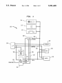
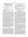
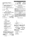
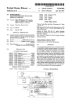
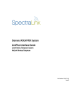
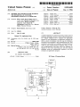
FIG. 1 depicts a digital telephone;
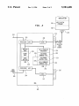
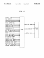
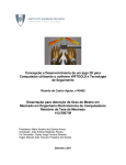
FIG. 2 is a more detailed diagram of the data communi
cations controller in the telephone of FIG. 1;
CROSS-REFERENCE TO RELATED
APPLICATION
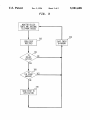
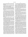
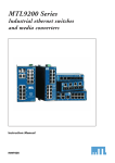
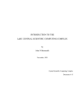
FIG. 3 is a ?ow chart of a method of event reporting by
the data communications controller of FIG. 2;
This is a continuation of Ser. No. 07/936,963 ?led Aug.
28, 1992, now abandoned.
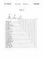
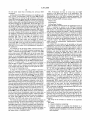
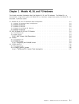
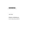
FIG. 4 is an exemplary format of a Set Event Mask (SEM)
command;
10
BACKGROUND OF THE INVENTION
A. Field of the Invention
This invention relates to a telephone control interface
system for use with digital telephones that are coupled to
programmable computer control.
Like reference numerals appearing in more than one
?gure represent like elements.
15
B. Related Art
A computer controllable telephone typically includes at
spontaneous reporting of ISDN call status events. The
application selects which ISDN call status events it is
interested in receiving and communicates the identity of
these events to the telephone by way of a Set Event Mask
exchange (PBX) and an asynchronous data communication
25
communicates with the phone via the data communication
spontaneously reported to the application program to those
puter can control the phone, accessing the various PBX
which were selected by the application.
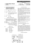
Turning ?rst to FIG. 1, a digital telephone 100 is coupled
to a PBX (not shown) by way of a network interface 102.
The network interface 102 translates the network protocol
telephony features by way of a command set. A typical
application would be, for example, an auto-dialer.
An increasingly popular network architecture is the inte
grated services digital network (ISDN). This network pro
vides many features, including enhanced telephony services.
(e. g. ROLMlink or ISDN) to the protocol of the telephone’s
internal data and control busses 124, 126 and handles
The enhanced telephony services provide ?exible control of
telephone calls and communication of status infonnation
about the telephone. Examples of ISDN call status informa
tion include call state, calling number, available features and
other events. By communicating the ISDN call status infor
transfers of telephone control information between a micro
processor 104 and the telephony line 101. The micropro~
cessor 104, is connected to the network interface 102. The
microprocessor 104 controls all of the telephone functions,
and is the source and destination for all communications
with the PBX. Also connected to the network interface and
mation to a host computer, via a telephone’s data commu
nications port, the operation of the telephone can be auto—
mated by a computer application program.
the microprocessor is a keypad and associated control logic
conventionally, the telephone’s data communications
45
events. Application based ?ltering requires additional pro
cessing time and real time usage of the host computer where
the application is running. Under this environment, tele
phony application programs must often be able to handle
50
events that are not pertinent to the desired task.
SUMMARY OF THE INVENTION
As a solution to the above-described problem, the present
invention provides a method and apparatus for selectively
passing various types of ISDN call status information
between the telephone’s data communication port and a
computer application program. In one embodiment, the
application program can select a subset of ISDN call status
spontaneously reported to the host computer and application
106. The keypad/control logic 106 includes the telephone
keys, light emitting diodes (LEDs) and the associated con
trol circuitry.
A coder/decoder (CODEC) 108 is connected to receive
data output from the network interface 102. The CODEC
108 converts digital audio information into analog form to
drive a speaker 110 and/or handset 112, and converts the
analog information from a microphone 114 and/or the hand
set 112 to digital information destined for the network
switch. The CODEC 108 is also connected to receive two
clock signals from the network interface. The ?rst of these
signals, the CODEC sync (CSYNC) 116, tells the CODEC
55
events by way of a telephony command to the telephone’s 60
data communication port. This command is processed by a
telephony command processor within the data communica
tion controller which, in turn, sets a programmable event
mask within the telephone. In response to the event mask
being set, only the selected ISDN call status events are 65
program.
(SEM) command. The SEM command is recognized by the
telephone’s telephony command processor which, in turn,
sets a mask in the telephony equipment. Once the mask is
set, the telephone will limit the ISDN call status events
port in a manner similar to that in which it would commu
nicate with a modem. Applications executing on the com
port will pass the ISDN call status information to the host
computer’s application program with no modi?cation. This
places the burden on the application to ?lter unwanted
DETAILED DESCRIPTION OF THE
PREFERRED EMBODIMENT
The present invention enables a user application program
to cause a connected telephone to selectively mask out
least two ports: a telephone line interface for connection
with a telephone network, and a data communication inter
face for communication with a computer. For example, a
telephone such as the ROLMphone (R) 244PC includes a
telephony port for providing connection to a private branch
port for providing connection to a computer. The computer
FIG. 5 illustrates the ?ow of events from the ISDN
network to the phone and then to the application.
when to read a ?eld in a data bus frame. The second, the
CODEC clock (CCLK) 118, is a bit clock which runs at the
bit transmission rate of the internal bus.
A digital LCD display 120 is also connected to the
microprocessor 104. The display 120 is used to display data
such as the number dialed, stored telephone numbers and
other data provided by way of the microprocessor 104.
A data communications controller (DCC) 122, controlled
by the microprocessor 104, provides the telephone with two
RS-232 data communications ports. The DCC 122 is con
nected to the network interface 102 and the microprocessor
104. Although signals from the CODEC 108 are made
available at the DCC interface, they are not used by the DCC
5,581,608
3
4
122. When a data connection is active, data from an option
mode (controlled by either the telephony command proces
sor or the data communications command processor).
The data communications command processor 224
handles data communications commands of the type well
ally connected RS-232 device ?ows through the telephone
and ROLMlink to the switch, from which it ?ows to another
line or device.
The control bus 126 is the path for phone control infor
mation which is sourced by the microprocessor. An audio
bus 128 carries analog audio information and provides an
analog path to and from the CODEC 108.
Optionally, an auxiliary processing apparatus 130 can be
provided. The auxiliary processing apparatus 130 is con
nected to the network interface 102 and the microprocessor
known in the art. The commands are sent by a connected
10
“AT” command set, with extensions for activating the tele
phony command processor(s).
104 and may also be connected to the CODEC 108. The data
The telephony control processor 221 handles the tele
communications controller 122 and the auxiliary processing
phony protocol that is received from the telephony network
link. It interprets and responds to telephony commands such
apparatus 130 can be of a “plug in” type which is installable
by the user.
as LED cadence commands and ISDN call status events. In
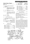
A more detailed view of the data communications con
addition, the telephony control processor 221 sends infor
troller 122 is illustrated in FIG. 2. The DCC 122 includes
two microprocessors 202, 204, each of which includes an
internal UART (Universal Asynchronous Receiver/Trans
mitter). The primary microprocessor 202 (a Motorola
68302) is connected to the telephone’s internal data bus 124,
the secondary microprocessor 204, a set of RS-232 trans
ceivers (XCVRS) 206, a random access memory (RAM)
208 and a read only memory (ROM) 210. The secondary
microprocessor 204 (a Motorola 6805) is connected to the
primary microprocessor 202, the control bus 126 and a
second set of transceivers (XCVRS) 212. The transceivers
206, 212 are, in turn, respectively connected to a ?rst
RS~232 port (PORTl) 214 and a second RS-232 port
apparatus (e.g. a workstation) via an RS-232 port. On power
up, the DCC defaults to command mode and the data
communications command processor 224. The data com
munications command processor controls the DCC in
response to commands in accordance with the conventional
mation from the telephone to the link, such as information
resulting from key depressions.
20
The telephony command processor 222 handles telephony
commands. Like the data communications commands, the
telephony commands are sent by a connected apparatus via
an RS-232 port. Once in command mode, a user can activate
25
the telephony command processor set by keying the proper
AT command sequence (e.g. AT % U).
The telephony command processor can include more than
one telephony command set, each of which can be entered
by way of a distinct AT command. The use of escape
sequences, a conventional data communications command
30 set (“AT” commands) and a conventional telephony com
(PORT2) 216.
r
mand set (“ROLM” commands) are described in more detail
The secondary microprocessor serves as a conduit
in the ROLMphone 244PC User’s Manual (copyright ‘1987,
between the primary microprocessor 202, and the control
bus 126 and second RS-232 port 216. The secondary micro
1988) available from ROLM Systems of Santa Clara Calif.
processor includes internal code to pass ISDN call status
events (received from the network via the control bus 126)
to the primary microprocessor 202 and to pass commands
and responses between the second communications port 216
The ROLMphone 244PC User’s Manual is incorporated by
and the primary microprocessor 202.
The RAM 208 provides workspace for the primary micro
as the CDLAPI) includes instructions for processing a set
event mask (SEM) command.
As illustrated in FIG. 2, a computer workstation 226 can
be coupled to either of the DCC’s communications ports
214,216 by way of its own RS-232 data communication port
228. An application program 230, executing on the work
station 226, sends commands and data to the DCC 122 via
the workstation’ s RS-232 port 228. According to an embodi
reference herein, in its entirety, as if printed in full below.
According to an embodiment of the present invention, the
telephony command processor 222 (hereinafter referred to
40
processor and includes a data buffer area for the RS-232
ports. The RAM also includes a devoted address location for
storing an event mask 218, which will be described in more
detail later. The ROM 210 includes a number of programs
(subroutines or processes) which are executed by the pri
mary microprocessor 202. These processes include a data
transfer processor 220, a telephony control processor 221, a
telephony command processor 222 and a data communica
tions command processor 224.
The data transfer processor 220 is a timer driven interrupt 50
routine. The timer (internal to the primary microprocessor
202) runs at a suf?cient rate to handle the necessary data
transfer speeds on the RS-232 ports and the telephony link.
The data communications command processor 224 and the
telephony control processor 221 run in a main control loop
225, each processing one piece of information if any is
present and then passing control to the next process. The
data communications command processor 224 calls the
55
transfers between the data bus 124 and the RS-232 commu
which ISDN call status events it is interested in having
spontaneously reported and communicates the identity of
these events to the CDLAPI 222 by way of the Set Event
Mask (SEM) command. The CDLAPI 222, in turn, sets a
mask .218 in the RAM. Once the mask is set, the processor
202 limits the ISDN call status events reported to the
application to those which were selected.
It should be understood that the SEM command actually
performs two functions. In normal operation (when the SEM
command has not been received by the CDLAPI) ISDN call
status events are not spontaneously reported to the RS-232
ports (and thus the application). Once the SEM command is
telephony command processor 222 whenever a user enters a
telephony command set (described in more detail later).
The data transfer processor 220 handles normal data
ment of the present invention, the application 230 selects
60
processed, the occurrence or change in state of any of the
selected events will be spontaneously (without further
request) reported to the application program via the RS-232
port on which the SEM command was received. In DCCs
including more than one RS-232 port, a separate event mask
enables a user or applications program, connected via an 65 location can be maintained for each. If an application wants
to change the set of events which are spontaneously
RS—232 port, to change the DCC from transparent mode
nications ports 214, 216. The data transfer processor 220
also includes code for processing the escape sequence which
(controlled by the data transfer processor) to command
reported, it issues another SEM command which overwrites
5,581,608
5
6
the old event mask (thus overriding the previous SEM
command).
FIG. 5 illustrates the ?ow of events from the ISDN
network to the phone and then to the application. The
A ?ow chart of the ISDN call status event handling in the
DCC of FIG. 2 is illustrated in FIG. 3. In step 302 an ISDN
call status event is received by the telephony control pro
cessor 221 from the control bus 126. In response to detection
application chooses events to be received by setting the
corresponding bit in the SEM command parameter. For
example, assume the application is only interested in receiv
ing the following ISDN call status events:
of the event, in step 304 the telephony control processor 221
Display Data
checks a status area in the Ram to determine if the CDLAPI
Call Substate
has been activated by an application. If the CDLAPI is not
Calling Party Number
active, in step 306 the telephony control processor 221 stores
From the DCC command mode, the application issues an
the ISDN call status event in the working area of the Ram
AT% U command to switch to the CDLAPI command
and returns to the control loop 225. If the CDLAPI is active,
processor. Next, the application issues the SEM command
in step 308 the telephony command processor 222 checks
with the bits corresponding to the display data, call substate
the event mask for the application and determines whether
and calling party number set (logical l) and the remainder of
the event is masked. If the event is not masked, in step 310
the bits reset (logical 0). In this case, the telephone and DCC
the telephony command processor 222 reports the event to 15 will still receive all the ISDN call status events, but the DCC
the application and returns control to the telephony control
will automatically send only a subset of the events to the
processor 221. Then, in step 306, the telephony control
application. It should be understood that the state of any
processor 221 stores the event in the working area of the
event can be reported to the application program by way of
RAM. At startup time (when the telephone is initially
a speci?c request. The SEM command only determines
powered up), the primary microprocessor 202 initializes the
which events are automatically (spontaneously) reported
event mask 218 so that all events are masked (reporting is
turned off). Thus, if no SEM commands are received by the
CDLAPI 222, no events will be spontaneously reported to
upon occurrence.
the application.
An example of the Set Event Mask command format is
illustrated in FIG. 4. The SEM command comprises three
?elds: a command length ?eld 402, a command code 404
25
'
A number of event masks can be provided so that each
application can execute its own SEM command. In such an
embodiment, each event mask would also include a ?eld of
information identifying the speci?c application to which it
pertains. When an ISDN call status event occurs, the micro
processor can scan the table and send a report to the
workstation, including the ISDN call status event and the
and an data (event) ?eld 406. Each bit in the event ?eld
controls the masking of a particular ISDN call status event 30 application identi?er for each application which is to auto
matically receive reporting of the event. Thus several appli
signal. As is conventional, unused bit positions are used as
cations attached to the same phone can receive different
place holders to format the SEM command into 8 bit octets.
subsets of the ISDN call status event signals.
The application chooses events to be signaled/received by
A number of enhancements can also be made to the above
setting the corresponding bit in the SEM command param
eter to
described embodiment. For example, the event mask 218
In other words, a “1” in a particular bit location 35 can be coupled to the phone keypad logic 106 such that it can
tells the DCC to signal a corresponding event to the appli
be manually programmed by a user. In this embodiment, the
telephone’s base microprocessor 104 can recognize user
cation, while a zero in a location will cause the event signal
to be masked such that the DCC will not signal the occur
rence of the corresponding event.
entry of a given access code (for example a user depressing
“S” “E” “M” on a the telephone’s keypad). In response, the
microprocessor 104 causes display 120 to display a mne
monic for each of the ISDN call status events. The mne
monics are cycled on the display 120 and enabled or
disabled one by one. As each mnemonic identifying a
particular ISDN call status event appears on the display, the
It should be understood that the telephony equipment
itself will continue to detect all ISDN call status events,
although it will only signal to the application those events
that were selected via the SEM command. Since all ISDN
call status events are stored in the RAM 208, the application
program can obtain the present status of any ISDN call status
event by issuing a feature status refresh (FSR) command.
The format of the FSR command is identical to that of the
SEM command except that the command codes are distinct
from one another and the event bits in the FSR command tell
the CDLAPI which stored events to report from the working
area of the RAM (rather than directly from the control bus
as with the SEM command). When the CDLAPI receives an
FSR command, it reads the status (in the working area of
RAM 208) of each of the ISDN call status events indicated
by the event ?eld and immediately reports this status (one
45
disable reporting of the identi?ed event. As an alternative a
hexadecimal SEM control word can be entered on the
keypad subsequent to the access code, thus programming the
event mask. In any event, the base microprocessor 104
50
reports the user’s selection to the DCC via the control bus
126. In response, the primary microprocessor 202 will set up
the event mask accordingly.
Now that the invention has been described by way of the
55
ments which do not depart from the scope and spirit of the
invention will become apparent to those of skill in the art.
Thus it should be understood that the preferred embodiment
preferred embodiment, various enhancements and improve
event at a time) to the application program. Unlike the SEM
command, the FSR command does not cause any changes to
the event mask 218 and will not cause the spontaneous
reporting of the ISDN call status events as they occur.
The format of events reported to the applications program
by way of the RS-232 port is also similar to that of the SEM
command of FIG. 4. Each report includes a data control
user enters a ‘1" to enable reporting of that event or a ‘O’ to
has been provided by way of example and not by way of
60
limitation.
The scope of the invention is de?ned by the appended
claims.
We claim:
(message length) ?eld, a distinct command code (indicating
1. A digital telephone comprising:
the event being reported) and a data ?eld which indicates the
status of the event (e. g. a calling name if the ISDN call status 65
event is CALLING NAME or a calling number if the ISDN
call status event is CALLING NO.).
a computer interface for coupling the telephone to a
computer running an application program for control
ling the masking of telephony events in the operation of
said telephone;
5,581,608
8
7
13. A method of operating a digital telephone, said
method comprising the steps of:
a network interface for coupling said telephone to a
communications network on which a plurality of tele
phony events occur;
detection means for detecting the occurrence of said
coupling said telephone to a computer implementing an
application program;
plurality of telephony events; and,
coupling said telephone to a communications network;
mask means coupled to said detection means and said
computer interface, wherein said mask means prevents
the reporting of masked telephony events to said com
puter and, in response to a command received from said
computer, said mask means allows the reporting of
non-masked telephony events, said non-masked tele
phony events being reported to said computer via said
computer interface as said non-masked telephony
setting an event mask in a memory in said telephone in
response to a command issued by said computer speci
fying telephony events to be masked, wherein masked
telephony events are not reported to said computer;
detecting a plurality of telephony events occurring on said
10
communications network; and,
selectively reporting, as they occur, only non-masked
telephony events to said computer.
14. The method of claim 13, further comprising the steps
events occur.
2. The digital telephone of claim 1, wherein said tele
phone is part of a telephone system.
3. The digital telephone of claim 1, wherein said tele
of:
storing data indicative of said plurality of telephony
phony events are call status events.
events as they occur; and,
in response to a second command issued by said com
4. The digital telephone of claim 1, further comprising:
storage means coupled to said detection means, for stor—
puter, causing data indicative of a ?rst subset of masked
telephony events to be reported to said computer.
15. The method of claim 14, further comprising the step
ing data indicative of said telephony events as they
occur; and,
'
command means coupled to said storage means, for
causing data to be reported to said computer as deter 25 of:
after reporting said ?rst subset of masked telephony
mined by said mask means.
5. The digital telephone of claim 1 further comprising:
events, issuing a third command by said computer, said
a keypad;
third command causing a second subset of said masked
telephony events to be reported to said computer.
programing means coupled to said keypad and said mask
means, for programming an event mask into said mask 30
16. Telephony event processing apparatus, comprising:
means via said keypad; and,
a display coupled to said programming means.
a computer interface for coupling to a computer imple
menting a computer program;
6. The digital telephone of claim 5, wherein said mask
a network interface for coupling to a communications
means is responsive to either of said programming means
35
and said command received from said computer.
detection means for detecting a plurality of telephony call
7. The digital telephone of claim 6, wherein said com
munications network is an Integrated Services Digital Net
work (ISDN).
8. The digital telephone of claim 7, wherein ones of said
telephony events are selected for reporting to said computer
via a single set mask code entered on said keypad.
9. The digital telephone of claim 7, wherein data indica
tive of said telephony events is displayed on said display.
10. The digital telephone of claim 9, wherein ones of said
telephony events are selected for reporting to said computer
via said computer interface by way of a single entry on said
keypad.
11. The digital telephone of claim 1, further comprising a
plurality of mask means, each mask means comprising
means for identifying a particular application program for
controlling the masking of telephony events from among a
plurality of application programs.
12. The digital telephone of claim 11, and further includ
ing processing means and memory means wherein said
network;
status events occurring on said communications net
work;
40
a memory; and,
processor means, coupled to said detection means, said
memory and said computer interface, for processing
commands received from said computer and for setting
an event mask in said memory in response to at least
one of said commands, said at least one of said com
45
mands specifying telephony call status events to be
masked, wherein masked telephony call status events
are not reported to said computer;
the processor means further comprising means for auto
matically reporting non-masked telephony call status
events indicated by said event mask to said computer.
17. The apparatus of claim 16, wherein said processor
means further comprises means for storing information
indicative of said telephony call status events.
18. The apparatus of claim 17, wherein said processor
means further comprises means for reporting said informa
telephony events are stored in a table within said memory 55
tion to said computer in response to a feature status refresh
means, and said processing means scans said table and
reports to said computer an application identi?er along with
non-masked telephony events for each of said application
programs.
command issued by said computer.