1
v1.12
Closer to Real,
User’s Manual
Dynamixel
ROBOTIS CO.,LTD. www.robotis.com
EX-106
EX-106
Contents
1. Introduction ··································································································2
1-1. What is Dynamixel ? ······················································································································· 3
1-2. Strong Points of Dynamixel ············································································································ 5
1-3. Specifications of EX-106················································································································· 6
2. Installation·····································································································7
2-1. How to Assemble Frames··············································································································· 8
2-2. Assembling Connector·················································································································· 10
2-3. Wiring ··········································································································································· 11
2-4. Connection of Main Controller ······································································································ 12
3. Communication with EX-106 ·····································································14
3-1. Overview of Communication········································································································· 15
3-2. Instruction Packet ························································································································· 16
3-3. Status Packet (Return Packet) ····································································································· 18
3-4. Control Table ································································································································ 20
3-5. How to Use Packet ······················································································································· 34
4. Appendix·······································································································46
1
EX-106
1. Introduction
What is Dynaimxel?
Strong Points of Dynamixel
Specifications of EX-106
2
EX-106
1-1. What is Dynamixel ?
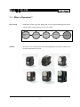
New Concept
Dynamixel is a robot-only Smart Actuator with a new concept integrating speed reducer,
controller, driver, network function, etc. into one module.
Reduction
Gear
LINE UP
Driver
Controller
Network
Dynamixel
We have Line up of several kinds of Dynamixel applicable numerously according to the
kinds and characteristics of robots
3
EX-106
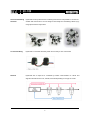
All-round Combining
Dynamixel is built up with all-round combining structure and it is possible to connect one
Structure
another with various forms. You can design a robot easily as if assembling a block toy by
using option frame for Dynamixel
Convenient Wiring
Dynamixel is connected with Daisy Chain and it is easy to wire one another.
Network
Dynamixel with a unique ID is controlled by Packet communication on a BUS and
supports networks such as TTL, RS485, and CAN depending on the type of model.
4
EX-106
1-2. Strong Points of Dynamixel
Torque
In spite of the compact size, it generates relatively big Torque by way of the efficient
speed reduction.
Close Control
It can control location and speed with the resolution of 4096.
Elasticity Setting
It can set up the extent of elasticity when controlling position with Compliance Driving.
Position, Speed
It can read the current position and speed.
Communication
It is easy to wire since it is connected with Daisy chain, and up to 1M BPS of
communication speed is supported.
Distribution Control
Since the main processor can set speed, position, compliance, torque, etc.
simultaneously with a single command packet, it can control several Dynamixels with a
little resource
Dual Mode Applicable Two units of EX-106 can be synchronized, that is, can be controlled simultaneously in a
parallel to increase the torque. As to dual mode setting for synchronization support, refer
to the section for 3-3-4. Dual Mode.
Physical Intensity
The main body is made of engineering plastic to withstand against strong external force.
Efficiency against
Since a bearing is used at the last axis of the gear, the amount of efficiency reduction is
External Force
minimal even if strong external force is applied to the axis.
Safety Device
It has the [Alarming] function, which notifies when internal temperature, torque, supplied
voltage, etc. deviate from what the user has set, and the [Shut down] function, which
allows it to cope with situation by itself.
Status Indicator
It informs the user of ERROR status via LED.
5
EX-106
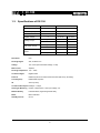
1-3. Specifications of EX-106
EX-106
Weight (g)
g
155
mm
40.2 x 65.4 x 46.0
Gear Reduction Ratio
-
1/164
Applied Voltage
V
at 14.8V
at 18.5V
kgf.cm
84
106
Nm
8.2
10.4
kgf.cm
55
69
Nm
5.4
6.8
Sec/60 degrees
0.182
0.143
rpm
54.9
69.9
Dimension (mm)
Holding Torque
MAX. Drive Torque
Speed
Resolution
0.07°
Running Degree
280°, Endless Turn
Voltage
12V~18.5V (Recommended voltage: 14.8V)
Max Current
3200mA
Running Temperature -5℃ ~ +85℃
Command Signal
Digital Packet
Protocol
RS485 Asynchronous Serial Communication (8bit,1stop, No Parity)
Link (Physical)
RS485 Multi Drop Bus
ID
254 ID (0~253)
Communication Speed 7343bps ~ 1 Mbps
Sensing & Measuring Position, Temperature, Load, Input Voltage, etc.
Material Quality
Full Metal Gear, Engineering Plastic Body
Motor
Maxon RE-MAX
Standby Current
55 mA
6
EX-106
2. Installation
1. How to Assemble Fames
2. Assembling Connectors
3. Wiring
4. Connection of Main Controller
7
EX-106
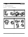
2-1. How to Assemble Frames
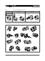
Optional Frames
EX-106 has the following
ng optional frames.
OF-106B
OF-106DH, OF-106DB
OF-106DH
OF-106DB
OF-106H
OF-64S
8
EX-106
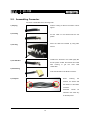
EX-106 has the following kinds of Horns.
Horn
Horn-64N
Basic Supply
Device Combination
Horn-64I
Horn-64T
Trust Bearing
Ball Bearing
The below picture shows examples of combinations by using optional frames and horns.
9
EX-106
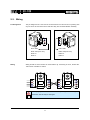
2-2. Assembling Connector
Connector is assembled in the following order.
Peel the coating of cable to the extent of 5mm
1) Striping
approx.
2) Inserting
Put the cable on the terminal like the left
picture.
Press the cable and terminal by using Wire
3) Forming
Former.
Combine the terminal to the cable tightly like
4) Formed Wire
the left picture. Solder the terminal and cable
after
Forming
to
get
the
more
solid
combination.
5) Assembling
Insert the terminal into 4P Molex connector.
When
6) Complete
inserting
the
terminal, be careful with
the direction of the Molex
connector.
Terminals
should
be
inserted in the same way
as the left picture
10
EX-106
2-3. Wiring
Pin Assignment
The pin assignment of a connector is as shown below. EX-106 can be run by linking with
any one of two 4P connectors of EX-106 since they are connected Pin2Pin internally.
1
2
3
4
4
3
2
1
Wiring
PIN1: GND
PIN1: GND
PIN2: VDD (12V~21V)
PIN2: VDD(12V~21V)
PIN3: D+
PIN3: D+
PIN4: D-
PIN4: D-
Wiring should be done Pin2Pin as shown below. By connecting as such, several EX106s can be controlled on a BUS.
1
2
3
4
4
3
2
1
1
2
3
4
4
3
2
1
Please pay special attention to avoid incorrect pin assignments in wiring.
Otherwise, EX-106 may be damaged.
Caution
11
EX-106
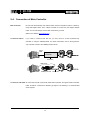
2-4. Connection of Main Controller
Main Controller
EX-106 uses the Multi-Drop Link method which connects several EX-106s to a Node by
using Half Duplex UART. Thus, a Main Controller to run EX-106 must support RS485
UART. You can also design and use Main Controller by yourself.
(Refer to the website www.robotis.com )
Connection with PC
If you want to control EX-106 with PC, you may control it via the Dynamixel-only
controller or using the USB2Dynmixel. For further information, refer to the Dynamixelonly controller manual or the USB2Dynmixel manual.
Serial
cable
Dynamixel-only
Controller
Power line
USB PORT
USB2Dynamixel
Power line
Connection with UART To control EX-106 with a personally made Main Controller, the signal of Main Controller
UART should be converted into RS485 type signal. The following is a recommended
circuit diagram.
12
EX-106
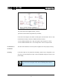
The power of EX-106 is supplied via Pin1(-), Pin2(+).
(The above circuit is built into Dynamixel-only controller.)
In the above circuit diagram, the direction of data signal of TxD and RxD in the TTL Level
is determined according to the level of DIRECTION 485 as follows:
In case of DIRECTION485 Level = High: The signal of TxD is output to D+ and D-.
In case of DIRECTION485 Level = Low: The signal of D+ and D- is output to RxD.
Confirmation of
The LED of EX-106 flickers once if the power is supplied to EX-106 properly via wiring.
Connection
Checking
If the above steps are not performed successfully, recheck the pin assignment of the
connector. If the pin assignment is right, check the allowable voltage and current of the
power supply.
Please check the current consumption when applying the power for the first
time. The current consumption of EX-106 in the standby state is 55mA or
Note
less.
13
EX-106
3. Communication with EX-106
1. Overview of Communication
2. Instruction Packet
3. Status Packet
4. Control Table
5. How to Use Packet
14
EX-106
3-1. Overview of Communication
To control EX-106, communication should be established according to the protocol of
EX-106. EX-106 is driven by receiving binary data. Examples of programs for the
transmission of this kind of data are described in detail in the User’s Manual of the
Dynamixel-only controller or the USB2Dynamixel.
Thus, this manual describes only the method and protocol of communication used in
EX-106 on the assumption that Main Controller can transfer binary data.
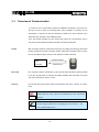
Packet
Main Controller and R-64 communicate each other by sending and receiving data called
Packet. Packet has two kinds: Instruction Packet, which Main Controller sends to control
EX-106, and Status Packet, which EX-106 responses to Main Controller.
Instruction Packet
Main
Controller
Role of ID
Status Packet
ID is a specific number for distinction of each EX-106 when several EX-106s are linked
to one bus. By giving IDs to Instruction and Status Packets, Main Controller can control
only the EX-106 that you want to control
Protocol
EX-106 does the Asynchronous Serial Communication with 8 bit, 1 Stop bit, and None
Parity.
If EX-106 with the same ID is connected, packet will collide and network
problem will occur. Thus, set ID as such that there is no EX-106 with the
Caution
same ID.
ID of EX-106 is changeable.
For this change, please refer to ‘Changing IDs of Ex.2 and Ex.7’. The
Note
factory default setting ID is 1.
15
EX-106
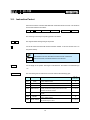
3-2. Instruction Packet
Instruction Packet is command data that Main Controller sends to EX-106. The structure
of Instruction Packet is as follows:
OXFF 0XFF ID LENGTH INSTRUCTION PARAMETER1 …PARAMETER N CHECK SUM
The meaning of each byte composing packet is as follows:
0XFF 0XFF
This signal notifies the beginning of the packet
ID
It is the ID of EX-106 which will receive Instruction Packet. It can use 254 IDs from 0 to
253 (0X00~0XFD).
Broadcasting ID : ID = 254 (0XFE)
If Broadcast ID is used, all linked EX-106s execute command of
Note
LENGTH
Instruction Packet, and Status Packet is not returned.
It is the length of the packet. The length is calculated as “the number of Parameters (N)
+ 2”.
INSTRUCTION
This command gives an instruction to EX-106 and has the following types.
Value
Name
0x01
PING
Function
No execution. It is used when controller is ready to
recevie Status Packet
0x02
READ DATA
0x03
WRITE DATA This command writes data to RX-64
0x04
0x05
0x06
0x83
This command reads data from RX-64
It is similar to WRTE_DATA, but it remains in the
standby state without being executed until the
ACTION command arrives.
This command initiates motions registered with REG
ACTION
WRITE
This command restores the state of RX-64 to the
RESET
factory default setting.
This command is used to control several RX-64s
SYNC WRITE
simultaneously at a time.
REG WRITE
16
No. of
Parameters
0
2
2 or more
2 or more
0
0
4 or more
EX-106
PARAMETER0…N
Parameter is used when Instruction requires ancillary data. For the usage of parameters,
refer to “3-5 How to Use Packet”
CHECK SUM
It is used to check if packet is damaged during communication. Check Sum is calculated
according to the following formula.
Check Sum = ~ ( ID + Length + Instruction + Parameter1 + … Parameter N )
Where, “~” is the Not Bit operator.
When the calculation result of the parenthesis in the above formula is larger than 255
(0xFF), use only lower bytes.
For example, when you want to use Instruction Packet like the below
ID=1 (0x01),
Length= 5 (0x05),
Parameter1= 12 (0x0C), Parameter2= 100 (0x64),
Check Sum
Instruction= 3 (0x03),
Parameter3= 170 (0xAA)
= ~ ( ID + Length + Instruction + Parameter1 + … Parameter 3 )
= ~ [ 0x01 + 0x05 + 0x03 + 0x0C + 0x64 + 0xAA ]
= ~ [ 0x123 ]
// Only the lower byte 0x23 executes the Not operation.
= 0xDD
Thus, Instruction Packet should be 0x01, 0x05, 0x03, 0x0C, 0x64, 0xAA, 0xDD.
17
EX-106
3-3. Status Packet (Return Packet)
EX-106 executes command received from the Main controller and returns the result to
the Main Controller. The returned data is called Status Packet. The structure of Status
Packet is as follows:
OXFF 0XFF ID LENGTH ERROR PARAMETER1 PARAMETER2…PARAMETER N
CHECK SUM
Each byte composing the packet means as below.
0XFF 0XFF
This signal notifies the beginning of the packet.
ID
It is the ID of EX-106 which transfers Status Packet.
LENGTH
It is the length of Status Packet, the value of which is“the number of Parameters (N) + 2”.
ERROR
It displays the error status occurred during the operatio of EX-106. The meaning of each
bit is described in the below table.
Bit
Name
Contents
Bit 7
0
-
Bit 6 Instruction Error
Bit 5 Overload Error
Bit 4 Checksum Error
Bit 3 Range Error
Bit 2 Overheating Error
Bit 1 Angle Limit Error
Bit 0 Input Voltage Error
In case of sending an undefined instruction or delivering
the action command without the reg_write command, it is
set as 1.
When the curren load cannot be controlled by the set
Torque, it is set as 1.
When the Checksum of the transmitted Instruction
Packet is incorrect, it is set as 1.
When a command is out of the range for use, it is set as
1
When internal temperature of Dynamixel is out of the
range of operating temperature set in the Control table, it
is set as 1.
When Goal Position is written out of the range from CW
Angle Limit to CCW Angle Limit , it is set as 1.
When the applied voltage is out of the range of operating
voltage set in the Control table, it is as 1.
18
EX-106
For example, when Status Packet is returned as below
0xFF 0xFF 0x01 0x02 0x24 0xD8
It means that the error of 0x24 occurs from EX-106 whose ID is 01. Since 0x24 is
00100100 as binary, Bit5 and Bit2 become 1. In order words, Overload and Overheating
Errors have occurred.
PARAMETER0…N
It returns data except ERROR. For the usage of parameters, refer to “3-5 How to Use
Packet".
CHECK SUM
It is used to check if packet is damaged during communication. The below formula
defines Check Sum. This formula is constructed in the same way as the Check Sum of
Instruction Packet.
Check Sum = ~ ( ID + Length + Error + Parameter1 + … Parameter N )
19
EX-106
3-4. Control Table
Control Table consists of data regarding the current status and operation, which exists inside of EX-106.
The user can control EX-106 by changing data of Control Table via Instruction Packet.
EEPROM Area
RAM Area
Address
(hexadecimal)
0 (0X00)
1 (0X01)
2 (0X02)
3 (0X03)
4 (0X04)
5 (0X05]
6 (0X06)
7 (0X07)
8 (0X08)
9 (0X09)
10 (0X0A)
11 (0X0B)
12 (0X0C)
13 [0X0D)
14 (0X0E)
15 (0X0F)
16 (0X10)
17 (0X11)
18 (0X12)
24 (0X18)
25 (0X19)
26 (0X1A)
27 (0X1B)
28 (0X1C)
29 (0X1D)
30 (0X1E)
31 (0X1F)
32 (0X20)
33 (0X21)
34 (0X22)
35 (0X23)
36 (0X24)
37 (0X25)
38 (0X26)
39 (0X27)
40 (0X28)
41 (0X29)
42 (0X2A)
43 (0X2B)
44 (0X2C)
46 (0X2E)
47 (0X2F)
48 (0X30)
49 (0X31)
56 (0X38)
57 (0X39)
Name
Model Number(L)
Model Number(H)
Version of Firmware
ID
Baud Rate
Return Delay Time
CW Angle Limit(L)
CW Angle Limit(H)
CCW Angle Limit(L)
CCW Angle Limit(H)
Drive Mode
the Highest Limit Temperature
the Lowest Limit Voltage
the Highest Limit Voltage
Max Torque(L)
Max Torque(H)
Status Return Level
Alarm LED
Alarm Shutdown
Torque Enable
LED
CW Compliance Margin
CCW Compliance Margin
CW Compliance Slope
CCW Compliance Slope
Goal Position(L)
Goal Position(H)
Moving Speed(L)
Moving Speed(H)
Torque Limit(L)
Torque Limit(H)
Present Position(L)
Present Position(H)
Present Speed(L)
Present Speed(H)
Present Load(L)
Present Load(H)
Present Voltage
Present Temperature
Registered Instruction
Moving
Lock
Punch(L)
Punch(H)
Sensed Current (L)
Sensed Current (H)
Description
Access
Lowest byte of model number
Highest byte of model number
Information on the version of firmware
ID of Dynamixel
Baud Rate of Dynamixel
Return Delay Time
Lowest byte of clockwise Angle Limit
Highest byte of clockwise Angle Limit
Lowest byte of counterclockwise Angle Limit
Highest byte of counterclockwise Angle
Limit
Dual Mode Setting
Internal Limit Temperature
Lowest Limit Voltage
Highest Limit Voltage
Lowest byte of Max. Torque
Highest byte of Max. Torque
Status Return Level
LED for Alarm
Shutdown for Alarm
Torque On/Off
LED On/Off
CW Compliance margin
CCW Compliance margin
CW Compliance slope
CCW Comliance slope
Lowest byte of Goal Position
Highest byte of Goal Position
Lowest byte of Moving Speed
Highest byte of Moving Speed
Lowest byte of Torque Limit
Highest byte of Torque Limit
Lowest byte of Current Position
Highest byte of Current Position
Lowest byte of Current Speed
Highest byte of Current Speed
Lowest byte of Current Load
Highest byte of Current Load
Current Voltage
Current Temperature
Means if Instruction is registered
Means if there is any movement
Locking EEPROM
Lowest byte of Punch
Highest byte of Punch
Lowest byte of Consuming Current
Highest byte of Consuming Current
R
R
R
RW
RW
RW
RW
RW
RW
RW
RW
RW
RW
RW
RW
RW
RW
RW
RW
RW
RW
RW
RW
RW
RW
RW
RW
RW
RW
RW
RW
R
R
R
R
R
R
R
R
RW
R
RW
RW
RW
R
R
20
Initial Value
(Hexadecimal)
106 (0X6A)
0 (0X00)
1 (0X01)
34 (0X22)
250 (0XFA)
0 (0X00)
0 (0X00)
255 (0XFF)
15 (0X0F)
0 (0X00)
80 (0X50)
60 (0X3C)
240 (0XF0)
255 (0XFF)
3 (0X03)
2 (0X02)
36 (0X24)
36 (0X24)
0 (0X00)
0 (0X00)
0 (0X00)
0 (0X00)
32 (0X20)
32 (0X20)
ADD14
ADD15
0 (0X00)
0 (0X00)
0 (0X00)
32 (0X20)
0 (0X00)
-
EX-106
RAM and EEPROM
Data in RAM area is reset to the initial value whenever the power is turned on while data
in EEPROM area is kept once the value is set even if the power is turned off.
Address
It represents the location of data. To read data from or write data to EX-106, the user
should assign an address where the data locates to Packet.
Access
EX-106 has two kinds of data: Read-only data, which is mainly used for sensing, and
Read-and-Write data, which is used for driving.
Initial Value
In case of data in the EEPROM Area, the initial values on the right side of the above
Control Table are the factory default settings. In case of data in the RAM Area, the initial
values on the right side of the above Control Table are the ones when the power is
turned on.
Highest/Lowest Byte
In the Control table, some data share the same name, but they are attached with (L) or
(H) at the end of each name to distinguish the address. This data requires 16bit, but it is
divided into 8bit each for the addresses (low) and (high). These two addresses should be
written with one Instruction Packet at the same time.
21
EX-106
3-4-1
Control Table Items ( EEPROM Area )
Model Number.
Address 0, 1 (0x00, 0x01) In case of EX-106, the data value is 64 (0X0040).
Firmware Version
Address 2 (0x02)
ID
Address 3 (0x03) It is a unique number to identify EX-106. 0 to 253 (0xFD) can be used
It represents the firmware version.
for it and the factory default setting is 1.
Baud Rate
Address 4 (0x04)
It represents the communication speed. 0 to 254 (0xFE) can be
used for it. This speed is calculated by using the below formula.
Speed (BPS) = 2000000 / ( Data + 1 )
Data value per Baud Rate
Data
Set BPS
Target BPS
Tolerance
1
1000000.0
1000000.0
0.000%
3
500000.0
500000.0
0.000%
4
400000.0
400000.0
0.000%
7
250000.0
250000.0
0.000%
9
200000.0
200000.0
0.000%
16
117647.1
115200.0
-2.124%
34
57142.9
57600.0
0.794%
103
19230.8
19200.0
-0.160%
207
9615.4
9600.0
-0.160%
If the tolerance of Baud Rate is less than 3 %, there is no
problem with communication. The initial value of Baud rate
Note
Return Delay Time
is 34 (0x22) (i.e., 57600bps).
Address 5 (0x05) It is the delay time that takes from the transmission of Instruction
Packet until the return of Status Packet. 0 to 254 (0xFE) can be used, and the delay time
per data value 1 is 2 usec. That is to say, if the data value is 10, 20 usec is delayed. The
initial value is 250 (0xFA) (i.e., 0.5 msec).
22
EX-106
Operating Angle Limit Address 6, 7, 8, 9 (0x06,0x07,0x08,0x09)
It
represents
the
allowed
range
of
movement. The range for use is 0 to 1023 (0x3FF). Data 0 denotes 0° and Data 1023
(0X3FF) 300°. Thus, the angle per data value 1 is about 0.3°.
Drive Mode
Address 10 (0x0A) When the dual mode connecting two units of EX-106 is used, data for
No. 10 address should be properly set up. In other words, one of the two EX-106 units
should be set to Master Mode for controlling, while the other to Slave Mode for linkage to
Master Mode. As to EX-106 to be used as Slave Mode, General Mode in the same
direction with EX-106 of Master Mode and Reverse Mode in the opposite direction
should be set up. For more information on Dual Mode, please refer to 3-4-4 Dual Mode.
As to Master Mode, set the EX-106 to No. 10 Address, and bit value 1 to 0.
As to Slave Mode, set the EX-106 to No. 10 Address, and bit value 1 to 1.
As to General Mode, set to No. 10 Address, and bit value 0 to 0.
In this case, the location values range from 0 to 4095.
As to Reverse Mode, set to No. 10 Address, and bit value 0 to 1.
In this case, the location values range from 4095 to 0. Reverse Mode reverses the
location values, which is convenient to make up a robot of bilateral joint
arrangement. For more information on Reverse Mode, refer to Goal Position on
page 29.
Bit
Name
Description
Bit 7
N/A
-
Bit 6
N/A
-
Bit 5
N/A
-
Bit 4
N/A
-
Bit 3
N/A
-
Bit 2
N/A
-
Bit 1
Master/Slave Mode
0: Master Mode;
1: Slave Mode
Bit 0
Normal/Reverse Mode
0: General Mode;
1: Reverse Mode
23
EX-106
Highest Limit
Address 11 (0x0B) It is the highest limit of operating temperature. The range for use is
Temperature
10 to 99 (0x10~0x63). If the internal temperature of EX-106 exceeds this range, Over
Heating Error Bit (Bit2) of Status Packet is returned as ‘1’ and Alarm is triggered as set in
the addresses 17 and 18. The value is equal to the actual Celsius temperature. In other
words, the initial value Data 80 (0x50) is 80℃.
Do not set The Highest Limit Temperature of EX-106 above the initial value
of 80℃. If EX-106 is used at the temperature of 80℃ or higher, it may be
Caution
damaged
Lowest / Highest
Address 12, 13 (0x0C, 0x0D) It is the operation range of voltage. 50 to 250
(0x32 ~
Limit Voltage
0x96) can be used. If Present Voltage (Address42) is out of the range, Voltage Range
Error Bit (Bit0) of Status Packet is returned as ‘1’ and Alarm is triggered as set in the
addresses 17 and 18. Data value is 10 times larger than actual voltage. For example, the
Lowest Limit Voltage Data of 80 means that the Lowest Limit Voltage is set as 8V.
Max Torque
Address 14, 15 (0x0E, 0x0F) It is the torque value of maximum output. 0 to 1023 (0x3FF)
can be used. The value set to ‘0’ means the Free Run state without torque. Max Torque
is allocated to EEPROM (Addresses 14 and 15) and RAM (Addresses 34 and 35). When
the power is turned on, EEPROM value is copied to RAM. In actual operation, the
maximum torque is restrained by Torque Limit (Addresses 34 and 35) located in RAM.
Data value represents the ratio of Torque output under the currently applied voltage. In
other words, Data 1023 (0x3FF) means that EX-106 will use 100% of the maximum
torque it can produce while Data 512 (0x200) means that EX-106 will use 50% of the
maximum torque. For stopping torque value according to the state of voltage of EX-106,
refer to “1-3 Specifications of EX-106”.
24
EX-106
Status Return Level
Address 16 (0X10) It decides how to return Status Packet. There are three ways like the
below table.
Address16
Return of Status Packet
0
No return against all instructions
1
Retrun only for the READ_DATA command
2
Return for all Instructions
When Instruction Packet is Broadcast ID, Status Packet is not returned
regardless of Status Return Level.
Note
When Instruction Packet is Ping, Status Packet is returned regardless of
Status Return Level.
Alarm LED
Address 17 (0X11) It shows an error status occurred during operation through LED.
Alarm LED is allocated with a bit according to each error content like the below table and
it flickers when the bit is set as 1 and the corresponding error occurs.
The function of each bit runs the logic of ‘OR’. That is to say, LED flickers even if 0X05
(binary 00000101) is set and Input Voltage Error or Overheating Error occurs. LED stops
flickering in two seconds when error occurs and is recovered to the normal state.
Bit
Name
Contents
Bit 7
0
-
Bit 6 Instruction Error
Bit 5 Overload Error
Bit 4 Checksum Error
Bit 3 Range Error
Bit 2 Overheating Error
Bit 1 Angle Limit Error
Bit 0 Input Voltage Error
When undefined Instruction is transmitted or the Action
command is delivered without the reg_write command
When the current load cannot be controlled with the set
maximum torque
When the Checksum of the transmitted Instruction Packet is
invalid
When the command is given beyond the range of usage
When the internal temperature is out of the range of
operating temperature set in the Control Table
When Goal Position is written with the value that is not
between CW Angle Limit and CCW Angle Limit
When the applied voltage is out of the range of operating
voltage set in the Control Table
25
EX-106
Alarm Shut down
Address 18 (0X12) It turns Torque off when an error occurs during operation. It also
allocates each error content in the same way as Alarm LED. It turns Torque off when the
Data bit is set as “1” and the applicable error occurs.
The function of each Bit runs the logic of ‘OR’ in the same way as Alarm LED. However,
unlike Alarm LED, the Torque OFF state is maintained even if an error occurs ans is
recovered to the normal state. To get out of the Shut down state, you should reset a
value you want into the Torque Limit (Addresses 34 and 35).
26
EX-106
3-4-2
Control Table Items ( RAM Area )
Torque Enable
Address 24 (0x18) When the power is supplied to EX-106 for the first time, EX-106 is in
the Free Run state in which case there is no torque generated. When Torque Enable is
set as "1”, Torque is generated.
LED
Address 25 (0x19) When it is set as “1”, LED is turned on; when it is set as “0”, LED is
turned off.
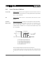
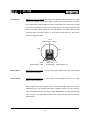
Compliance
Address 26~29 (0x1A~0x1D) Compliance is to set the pattern of output torque. Making
Margin & Slope
well use of it will result in shock absorption, smooth motion, etc. The length of A, B, C,
and D in the below graph ( Position vs. Torque curve ) is the value of Compliance.
Compliance Margin is available from 0 to 254 (0xFE) while Compliance Slope is valid
from 1 to 254 (0xFE).
Goal Position
CCW
E
CW
E
CW
Y axis: Output Torque
A
B
C
CCW
X axis: Position
D
A : CW Compliance Slope (Address 28)
B : CW Compliance Margin (Address 26)
C : CCW Compliance Margin (Address 27)
D : CCW Compliance Slope (Address 29)
E : Punch (Address 48, 49)
B and C (Compliance Margin) are the areas where output torque is 0.
A and D (Compliance Slope) are the areas where output torque is reduced when they
are getting close to Goal Position. The wider these areas are, the smoother the motion
is.
27
EX-106
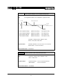
Compliance Slope can be defined as seven levels in total as shown in the below table. It
recognizes the data values 1 to 5 as 4, valid position value, while the data values 6 to 11
as 8. Thus, it is convenient to set up the data of Compliance Slope as the valid position
value in the below table. The initial value is 32 (0x20) in the 4th level.
Level
Data Value
Valid Position Value
1
1 (0x00)
~ 5 (0x05)
4 (0x04)
2
6 (0x00)
~ 11 (0x0B)
8 (0x08)
3
12 (0x0C) ~ 23 (0x17)
16 (0x10)
4
24 (0x18) ~ 47 (0x2F)
32 (0x20)
5
48 (0x30) ~ 95 (0x5F)
64 (0x40)
6
96 (0x60) ~191 (0xBF)
128 (0x80)
7
192 (0xC0)~254 (0xFE)
254 (0xFE)
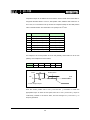
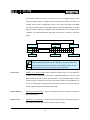
For example, if the current position is set as 200 (0X0C8), Goal Position is set as 512
(0X200), and Compliance is set as below,
Area
A
B
C
D
E
Data
16
5
5
16
10
Goal Position
CCW
10
CW
200
491
507
512 517
CCW
X axis: Position
CW
Y axis: Output Torque
From the current position 200 to 491 ( 512-16-5=491 ), movement is made with
appropriate torque to reach the set speed; from 491 to 507 ( 512-5=507 ), torque is
continuously reduced to the Punch value; from 507 through 517 ( 512+5=517 ), no
torque is generated.
28
EX-106
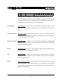
Goal Position
Address 30, 31 (0X1E, 0x1F) is the value for the desired location; values from 0 to 4095
(0xFFF) are available. The location values for data value are described in the figure
below. Goal Position shall be within the range of CW Angle Limit ≤ Goal Potion ≤ CCW
Angle Limit, and otherwise, Angle Limit Error takes place. As to Reverse Mode, the data
values and location values reverse as in the figure below. For example, when the data
values are 4095, the location value is 0°, and when the data value is 0, the location
values are changed to 280.6°.
140.3°
(Goal Position = 0x800)
CCW
CW
280.6°
(Goal Position = 0xfff)
Moving Speed
Address 32, 33 (0x20, 0x21)
280.6~360°
0°
Invalid Angle
(Goal Position = 0)
It is a moving speed to Goal Position. 0 to 1023 (0X3FF)
can be set for the speed.
Present Speed
Address 38, 39 (0x26,0x27)
It is the current moving speed of EX-106. 0 to 1023
(0X3FF) can be measured.
Moving Speed and Present Speed can be converted into RPM when data value is
multiplied by 0.111. For example, Data 1023 is 114RPM ( 1023x0.111=113.6 ). But, the
maximum speed of EX-106 is less than 114RPM. Nevertheless, the range of speed data
value is set up to 114 RPM since EX-106 can move faster than the maximum speed by
outside factors.
29
EX-106
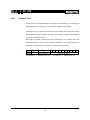
The maximum speed of EX-106 is in proportion to the size of supplied voltage. In other
words, the higher voltage it is supplied with, the wider range of speed it can control. For
example, when EX-106 is supplied with 18.5V, it can reach to the speed of 69.9RPM
and control the speed with 0 to 69.9 RPM. However, when it is supplied with 14.8V, the
maximum speed is reduced to 54.9RPM so that the speed with 0 to 54.9 RPM can be
controlled. The relationship between data value and speed is as shown in the below
picture.
EX-106, Max. Moving Speed & Data Value at 18.5V
Min. Speed
RPM
69.9 RPM
114 RPM
627 (0x273)
1023 (0x3FF)
Available area
Data
1 (0X001)
When Moving Speed is set as 1 (0X001), movement is made at the minimum
speed. When Moving Speed is set as 0 (0x000), movement is made at the
Note
maximum speed which can be reached under the applied voltage. In other
words, setting as 0 means that no speed control will be done.
Torque Limit
Address 34, 35, (0x22, 0x23) It sets the maximum output Torque. 0 to 1023 (0x3FF) is
available. Torque related data is allocated in EEPROM (Addresses 14 and 15) and
RAM (Addresses 34 and 35). And when the power is on, the EEPROM value is copied
to RAM. Torque is restricted by the Torque Limit value located in RAM (Addresses 34
and 35) in driving. Data value represents the ratio of Torque that can be output under the
currently applied voltage as described in Max Torque
Present Position
Address 36, 37 (0x24,0x25)
It is the current position of EX-106. The unit is the same as
that of Goal Position.
Present Load
Address 40, 41 (0x28,0x29)
It is the size of the load currently being driven by EX-106.
The meaning of data per each bit in the Present Load is as below.
30
EX-106
BIT
15~11
10
Value
0
Load Direction
9
Load Direction = 0 : CCW Load,
8
7
6
5
4
3
2
1
0
Data (Load Ratio)
Load Direction = 1: CW Load
Data value indicates the ratio of Torque as described in Max Torque. For example, data
value is 1023 (0X3FF) when the maximum torque is generated but the load is too big for
EX-106 to move, so that EX-106 ends up in the holding state.
Present Voltage
Address 42 (0x2A)
It is the size of the current voltage supplied. This value is 10 times
larger than the actual voltage. For example, when 10V is supplied, the data value is 100
(0x64).
Present Temperature
Address 43 (0x2B) It is the internal temperature of EX-106 in Celsius. Data value is
identical to the actual temperature in Celsius. For example, if the data value is 85 (0x55),
the current internal temperature is 85℃.
Registered Instruction Address 44 (0x2C)
It is set as “1” when a command is registered by the REG_WRITE
command of Instruction Packet. Then, it changes into “0” after executing a registered
command by the Action command.
Moving
Address 46 (0x2E) It is set as “1” while movement is being made with Goal Position set;
it changes into “0” when Goal Position is reached.
Lock
Address 47 (0x2F)
Setting it as “1” leads to the lock state and only the values from
Address 24 (0X18) to Address 35 (0x23) are writable. Once locked, it is impossible to
unlock unless the power is off.
Punch
Address 48, 49 (0x30,0x31) It is the limit value of torque being reduced when the output
torque is decreased in the Compliance Slope area. In other words, it is the mimimum
torque. The initial value is 32 (0x20) and can be extended up to 1023 (0x3FF). (Refer to
Compliance margin & Slope)
31
EX-106
3-4-3
Endless Turn
Endless Turn can be materialized when CW Angle Limit (Address 6,7) and CCW Angle
Limit (Address8,9) are set as “0”. It can be usefully applied to move wheels.
Endless Turn has no speed control function. Enter a desired torque value into Moving
Speed (Addresses 32 and 33 (0X20 and 0X21)). The meaning of Moving Speed Address
is as shown in the below picture.
Data value in the table represents the ratio of output torque. For example, Data 1023
(0x3FF) means that 100% of torque should be generated in the current voltage state
while data 512 (0x200) means that 50% of torque should be generated.
BIT
15~11
10
Value
0
Turn Direction
Turn Direction = 0 : CCW Direction Turn,
32
9
8
7
6
5
4
3
2
1
Data (Torque Ratio)
Turn Direction = 1: CW Direction Turn
0
EX-106
3-4-4
Dual Mode
To drive two units of EX-106, set the EX-106 in the following order:
1. Set different IDs for the two units of EX-106.
2. Set one of the two units to Slave Mode (the default value is Master Mode). To set it to
Slave Mode, adjust bit 1 value of the drive mode address (address 0x0A ) to 1. It is EX106 that Ex-106 with the bit 1 value of Drive Mode is 1 is converted into Slave mode.
For more information, please refer to Drive Mode on page 23.
3. Turn off and again, turn on the EX-106 you have converted into Slave Mode or reset it.
Slave Mode setting is applied after reboot. EX-106 converted into Slave Mode blinks
LED three times upon rebooting.
4. Connect two units of EX-106 by means of synchronization cables. There are two
kinds of synchronization cables: General Mode and Reverse Mode.
5. Check if the Slave Ex-106 and Master EX-106 are operated simultaneously by
attempting communication regarding the operation command with Master EX-106.
Convert into Slave Mode
Synchronization cable for
General Mode
Synchronization cable for
Reverse Mode
Synchronization Cable
※ twisted cords
Slave EX-106 is synchronized by directly receiving the control command
through synchronization cable from Master EX-106. Slave Mode unit
Note
responds to communication through command packets, but data related to
motor drive are processed only through the synchronization
33
EX-106
3-5.
How to Use Packet
To operate EX-106, Instruction Packet, which is binary type data, should be sent to EX106 from Main Controller. Instruction Packet has seven kinds of commands. (Refer to
“3-2 Instruction Packet”)
In addition, EX-106 receives Instruction Packet to performs a command and returns the
result as Status Packet to Main Controller. This section describes examples of the usage
of each command of Instruction Packet.
3-5-1
READ DATA
Function
This command is to read data in the Control Table inside of EX-106.
Length
0X04
Instruction
0X02
Parameter1
Start Address of data to be read
Parameter2
Length of Data to be read
Example 1
Reads the current internal temperature of EX-106 whose ID is 1.
Reads 1 byte from the value of Address 43 (0x2B) in the Control Table.
Instruction Packet : 0XFF 0XFF 0X01 0X04 0X02 0X2B 0X01 0XCC
ID LENGTH INSTRUCTION PARAMETERS
CHECKSUM
Status Packet returned is as follows:
Status Packet : 0XFF 0XFF 0X01 0X03 0X00 0X20 0XDB
ID LENGTH ERROR PARAMETER1 CHECKSUM
Data value read is 0x20 (i.e., 32 in decimal). Thus, the current internal temperature of
EX 106 i 32℃ (0X20)
34
EX-106
3-5-2
WRITE DATA
Function
This command is to write data to the Control Table inside of EX-106.
Length
N+3 (if the number of writing data is N)
Instruction
0X03
Parameter1
Start address to write data
Parameter2
First data to write
Parameter3
Second data to write
Parameter N+1
Nth Data to write
Example 2
Sets the ID of EX-106 as “1’”.
Writes 1 to the Address 3 in the Control Table.
Sends ID as Broadcasting ID(0xFE).
Instruction Packet : 0XFF 0XFF 0XFE 0X04 0X03 0X03 0X01 0XF6`
ID LENGTH INSTRUCTION PARAMETERS.CHECKSUM
Status Packet is not returned since Broadcast ID (0XFE) is transmitted.
35
EX-106
3-5-3
REG WRITE
The REG_WRITE command is similar to the WRITE_DATA command in terms of
Function
function, but differs in terms of the timing that a command is executed. When Instruction
Packet arrives, it is saved in Buffer and the Write operation remains in the standby state.
At this moment, Registered Instruction (Address 44 (0x2C)) is set as “1”. Then, when
Action Instruction Packet arrives, Registered Instruction changes into “‘0” and the
registered Write command is finally executed.
Length
N+3 (if the number of Writing Data is N)
Instruction
0X04
Parameter1
Start Address to write Data
Parameter2
First data to write
Parameter N+1
Nth data to write
3-5-4
ACTION
Function
This command is to execute the Write action registered by REG_WRITE
Length
0X02
Instruction
0X05
Parameter
NONE
The Action command is useful when several EX-106s are moved with accuracy at the
same time. When several running gears are controlled via communication, there is a
little time difference in terms of enabling time between the first and the last running gear
getting commands. EX-106 has resolved this problem by using Action Instruction.
In case of transmiting the Action command to more than two EX-106s,
Broadcast ID(0XFE) should be used, but Status Packet is not returned at
Note
this time.
36
EX-106
3-5-5
Function
PING
This command does not instruct anything. It is only used when receiving Status Packet
or confirming the existence of EX-106 with a specific ID.
Length
0X02
Instruction
0X01
Parameter
NONE
Example 3
Receives Status Packet of EX-106 whose ID is 1.
Reads 1 byte from the value of Address 43 (0x2B) in the Control Table.
Instruction Packet : 0XFF 0XFF 0X01 0X02 0X01 0XFB`
ID LENGTH INSTRUCTION CHECKSUM
Status Packet returned is as follows:
Status Packet : 0XFF 0XFF 0X01 0X02 0X00 0XFC
ID LENGTH ERROR CHECKSUM
Although Status Return Level (Address 16 (0X10)) is 0, it returns Status
Packet all the time for Ping Instruction. But, it does not return Status Packet
Note
when Check Sum Error occurs in spite of using PING Instruction.
37
EX-106
3-5-6
RESET
Function
This command is to reset the Control Table of EX-106 to the factory default setting.
Length
0X02
Instruction
0X06
Parameter
NONE
Example 4
Resets the Control Table of EX-106 whose ID is 0.
Instruction Packet : 0XFF 0XFF 0X00 0X02 0X06 0XF7`
ID LENGTH INSTRUCTION CHECKSUM
Status Packet returned is as follows:
Status Packet : 0XFF 0XFF 0X00 0X02 0X00 0XFD
ID LENGTH ERROR CHECKSUM
Please note that ID is changed into”‘1” after the execution of the RESET command.
Please note that the value set by the user is removed when the RESET
command is used.
Caution
38
EX-106
3-5-7
SYNC WRITE
Function
This command is used to control several EX-106s simultaneously with one Instruction
Packet transmission. When this command is used, several commands are transmitted at
once, so that the communication time is reduced when multiple EX-106s are controlled.
However, the SYNC WRITE command can be used only if both of the address and
length of the Control Table to write is identical. Besides, ID should be transmitted as
Broadcasting ID. Make sure that the length of packet does not to exceed 143 bytes since
the volume of receiving buffer of EX-106 is 143 bytes.
ID
0XFE
Length
(L+1) X N + 4
Instruction
0X83
Parameter1
Start address to write Data
Parameter2
Length of Data to write
Parameter3
First ID of EX-106
Parameter4
First data of the first EX-106
Parameter5
Second data of the first EX-106
…
Parameter L+3
Lth Data of the first EX-106
Parameter L+4
ID of the second EX-106
Parameter L+5
First data of the second EX-106
Parameter L+6
Second data of the second EX-106
…
Parameter 2L+4
Lth data of the second EX-106
Example 5
(L: Data Length per EX-106, N: the number of EX-106s)
Data regarding the first EX106
Data regarding the second EX106
Moves to the following position and speed for each EX-106.
EX-106 with ID 0 : Moves to the position of 0x010 at the speed of 0x150
EX-106 with ID 1 : Moves to the position of 0x220 at the speed of 0x360
EX-106 with ID 2: Moves to the position of 0x030 at the speed of 0x170
EX-106 with ID 3: Moves to the position of 0x220 at the speed of 0x380
Instruction Packet : 0XFF 0XFF 0XFE 0X18 0X83 0X1E 0X04 0X00 0X10 0X00
0X50 0X01 0X01 0X20 0X02 0X60 0X03 0X02 0X30 0X00
0X70 0X01 0X03 0X20 0X02 0X80 0X03 0X12`
Status Packet is not returned since ID is transmitted as Broadcasting ID.
39
EX-106
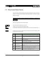
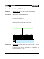
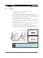
3-5-8
Other Examples
The following examples are supposed that ID is 1 and Baud rate is 57142 BPS.
Example 6
Reads the Model Number and Firmware Version.
Instruction = READ_DATA,
Hint
Address = 0x00,
Length = 0x03
Instruction Packet : FF FF 01 04 02 00 03 F5
Communication
Status Packet : FF FF 01 05 00 40 00 08 7D
Status Packet Result
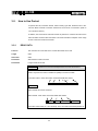
Example 7
Model Number = 64 (0x40) Firmware Version = 0x08
Changes the ID of EX-106 from 1 to 0.
Hint
Instruction = WRITE_DATA, Address = 0x03, DATA = 0x00
Communication
Instruction Packet : FF FF 01 04 03 03 00 F4
Status Packet : FF FF 00 02 00 FC
Status Packet Result
Example 8
NO ERROR
Changes the Baud Rate to 1M bps.
Hint
Instruction = WRITE_DATA, Address = 0x04, DATA = 0x01
Communication
Instruction Packet : FF FF 01 04 03 04 01 F3
Status Packet : FF FF 01 02 00 FD
Status Packet Result
NO ERROR
40
EX-106
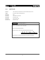
Example 9
Resets Return Delay Time as 4usec.
Instruction = WRITE_DATA, Address = 0x05,
Hint
DATA = 0x02
Instruction Packet : FF FF 01 04 03 05 02 F1
Communication
Status Packet
Status Packet Result
: FF FF 01 02 00 FD
NO ERROR
Return Delay Time Data 1 is equal to 2usec.
It is recommended that Return Delay Time be set as the minimum value
Note
within the allowed range of Main Controller.
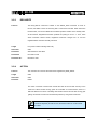
Example 10
Restricts the movement angle from 0 to 150°.
Since CCW Angle Limit 0x3FF means 300°,
Hint
150°corresponds to 0x200.
Instruction = WRITE_DATA, Address = 0x08,
DATA = 0x00, 0x02
Instruction Packet : FF FF 01 05 03 08 00 02 EC
Communication
Status Packet
Status Packet Result
Example 11
: FF FF 01 02 00 FD
NO ERROR
Resets the highest limit of operating temperature as 80°.
Hint
Instruction = WRITE_DATA, Address = 0x0B,
DATA = 0x50
Communication
Instruction Packet : FF FF 01 04 03 0B 50 9D
Status Packet
Status Packet Result
NO ERROR
41
: FF FF 01 02 00 FD
EX-106
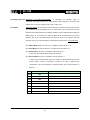
Example 12
Sets the operating voltage as 10 to 17V.
Data of 10V is 100 (0x64) while 17V is 170 (0xAA).
Hint
Instruction = WRITE_DATA, Address = 0x0C,
DATA = 0x64, 0xAA
Instruction Packet : FF FF 01 05 03 0C 64 AA DD
Communication
Status Packet
Status Packet Result
Example 13
: FF FF 01 02 00 FD
NO ERROR
Only generates 50% of the maximum torque.
Sets the value of MAX Torque located in the EEPROM
Hint
area
as 0x1FF, which is 50% of the maximum value 0x3FF.
Instruction = WRITE_DATA, Address = 0x0E,
DATA = 0xff, 0x01
Instruction Packet: FF FF 01 05 03 0E FF 01 E9
Communication
Status Packet
Status Packet Result
: FF FF 01 02 00 FD
NO ERROR
The change of Max Torque can be checked by turning the power off and then on.
Example 14
Do not return Status Packet all the time.
Hint
Instruction = WRITE_DATA, Address = 0x10,
DATA = 0x00
Communication
Instruction Packet: FF FF 01 04 03 10 00 E8
Status Packet : FF FF 01 02 00 FD
Status Packet Result
NO ERROR
Status Packet is not returned from the next Instruction.
42
EX-106
Example 15
Sets the Alarm as such that LED flickers and shutdown (torque off)
when the operating temperature is higher than the limit temperature.
Since Overheating Error is Bit 2, set up Alarm value as
Hint
0x04. ( 0x04=00000100 )
Instruction = WRITE_DATA, Address = 0x11,
DATA = 0x04, 0x04
Instruction Packet: FF FF 01 05 03 11 04 04 DE
Communication
Status Packet : FF FF 01 02 00 FD
Status Packet Result
Example 16
NO ERROR
Turns on the LED and enables Torque.
Instruction = WRITE_DATA, Address = 0x18,
Hint
DATA = 0x01, 0x01
Instruction Packet: FF FF 01 05 03 18 01 01 DD
Communication
Status Packet : FF FF 01 02 00 FD
Status Packet Result
NO ERROR
You can check the Torque Enable state by touching the axis of Dynamixel you’re
your hand.
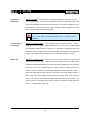
Example 17
Locates at the Position 180° with the speed of 57RPM.
Hint
Sets Goal Position (Address 30 (0x1E))= 511 (0x1FF) and
Moving Speed (Address 0x20))= 512 (0x200).
Instruction = WRITE_DATA, Address = 0x1E,
DATA = 0x00, 0x02, 0x00, 0x02
Communication
Instruction Packet: FF FF 01 07 03 1E 00 02 00 02 D3
Status Packet : FF FF 01 02 00 FD
Status Packet Result
NO ERROR
43
EX-106
Example 18
Sets Compliance Margin=1 and Compliance Slope=0x40.
The suggested condition can be depicted in a graph as below.
Hint
Goal Position
CCW
CCW
CW
0x41(CW) 0x01(CW)
0x01(CCW) 0x41(CCW)
Angle
(Position Error)
CW
A: CCW Compliance Slope
(Address 29 (0x1D))
= 0x40 (about 18.8°)
B: CCW Compliance Margin
(Address 27 (0x1B))
= 0x01 (about 0.3°)
C: CW Compliance Margin
(Address 26 (0x1A))
= 0x01 (about 0.3°)
D: CW Compliance Slope
(Address 28 (0x1C))
= 0x40 (about 18.8°)
Instruction = WRITE_DATA, Address = 0x1A,
DATA = 0x01, 0x01, 0x40, 0x40
Communication
Instruction Packet: FF FF 01 07 03 1A 01 01 40 40 59
Status Packet : FF FF 01 02 00 FD
Status Packet Result
Example 19
NO ERROR
Sets the minimum output Torque (Punch) as 0x40.
Hint
Instruction = WRITE_DATA, Address = 0x30,
DATA = 0x40, 0x00
Communication
Instruction Packet : FF FF 01 05 03 30 40 00 87
Status Packet
Status Packet Result
NO ERROR
44
: FF FF 01 02 00 FD
EX-106
Example 20
Locates EX-106 with ID 0 at Position 0° and EX-106 with ID 1 at
Position 300°. Start only two EX-106s at the same point.
When the WRITE_DATA command is used, two EX-106s
Hint
cannot be started at the same point.
Thus, REG_WRITE and ACTION are used.
ID=0, Instruction = REG_WRITE, Address = 0x1E,
DATA = 0x00, 0x00
ID=1, Instruction = REG_WRITE, Address = 0x1E,
DATA = 0xff, 0x03
ID=0xfe(Broadcasting ID), Instruction = ACTION,
Communication
Instruction Packet: FF FF 00 05 04 1E 00 00 D8
Status Packet : FF FF 00 02 00 FD
Instruction Packet: FF FF 01 05 04 1E FF 03 D5
Status Packet : FF FF 01 02 00 FC
Instruction Packet: FF FF FE 02 05 FA (LEN:006)
Status Packet
Status Packet Result
Example 21
//No return packet
NO ERROR
Unable to change values except Address 24 to Address 35.
Hint
Sest Lock ( Address 47 (0x2F) ) as 1.
Instruction = WRITE_DATA, Address = 0x2F,
DATA = 0x01
Communication
Instruction Packet : FF FF 01 04 03 2F 01 C8
Status Packet
Status Packet Result
: FF FF 01 02 00 FD
Status Packet Result
NO ERROR
Once locked, It is impossible to unlock unless the power is off.
When other data is accessed while locked, an error is returned.
45
EX-106
4. Appendix
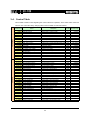
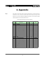
Range
Each data has valid range. When the Write commancd that is off the valid range is
transmitted, an error is returned. The below table shows the length and range of data
that the user can write. 16bit Data is displayed in two bytes, L and H. These two bytes
should be written as one Instruction Packet at once.
[Control Table Data Range and Length for Writing]
Write
Address
3(0X03)
ID
0
253(0xfd)
4(0X04)
Baud Rate
1
0
254(0xfe)
5(0X05)
Return Delay Time
1
0
254(0xfe)
6(0X06)
CW Angle Limit
2
0
1023(0x3ff)
8(0X08)
CCW Angle Limit
2
0
1023(0x3ff)
Writing Item
Length
(bytes)
1
Min
Max
11(0X0B)
the Highest Limit Temperature
1
10(0x10)
99(0x63)
12(0X0C)
the Lowest Limit Voltage
1
50(0x32)
250(0xfa)
13(0X0D)
the Highest Limit Voltage
1
50(0x32)
250(0xfa)
14(0X0E)
Max Torque
2
0
1023(0x3ff)
16(0X10)
Status Return Level
1
0
2
17(0X11)
Alarm LED
1
0
127(0x7f)
18(0X12)
Alarm Shutdown
1
0
127(0x7f)
19(0X13)
(Reserved)
1
0
1
24(0X18)
Torque Enable
1
0
1
25(0X19)
LED
1
0
1
26(0X1A)
CW Compliance Margin
1
0
254(0xfe)
27(0X1B)
CCW Compliance Margin
1
0
254(0xfe)
28(0X1C)
CW Compliance Slope
1
1
254(0xfe)
29(0X1D)
CCW Compliance Slope
1
1
254(0xfe)
30(0X1E)
Goal Position
2
0
1023(0x3ff)
32(0X20)
Moving Speed
2
0
1023(0x3ff)
34(0X22)
Torque Limit
2
0
1023(0x3ff)
44(0X2C)
Registered Instruction
1
0
1
47(0X2F)
Lock
1
0
1
48(0X30)
Punch
2
0
1023(0x3ff)
46
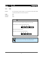
EX-106
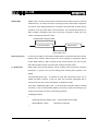
RS485 UART is a serial communication method that TxD and RxD cannot be executed
RS485 UART
simultaneously. It is usually used when connecting several communication equipments
to one BUS. Since multiple devices are connected to the same BUS, all other devices
should be in the input state while a device transmits. The communication direction of
Main Controller controlling EX-106 is set as input and is changes to output only in the
course of transferring Instruction Packet.
RS485 Direction Output Duration
Instruction Packet
Status Packet
Return Delay Time
Return Delay Time
It is the time that takes to returns Status Packet after EX-106 receives Instruction Packet.
Default value is 160uSec. Return Delay Time can be changed by changing the data of
Control Table Address 5. Main Controller should convert Direction Port into the input
state within the Return Delay Time frame after sending Instruction Packet.
Tx, Rx Direction
Rs485 UART should change Direction into the receiving mode at the time of finishing
transmission. In general, CPU has the following BITs showing UART_STATUS in the
register.
TXD_BUFFER_READY_BIT : It indicates the state that Transmission DATA can be
loaded into Buffer. However, it does not mean that previously transmitted data is
removed from CPU, but it means that SERIAL TX BUFFER is empty.
TXD_SHIFT_REGISTER_EMPTY_BIT : It is set when all Transmission Data is unloaded
from CPU. In case of TXD_BUFFER_READY_BIT, this bit is used when sending a byte
in serial communication as shown in the following example.
TxDByte(byte bData)
{
while(!TXD_BUFFER_READY_BIT); //wait until data can be loaded.
SerialTxDBuffer = bData;
}
47
//data load to TxD buffer
EX-106
You should check TXD_SHIFT_REGISTER_EMPTY_BIT at the time of changing
direction. The following example is a program sending Instruction Packet.
LINE 1
DIRECTION_PORT = TX_DIRECTION;
LINE 2
TxDByte(0xff);
LINE 3
TxDByte(0xff);
LINE 4
TxDByte(bID);
LINE 5
TxDByte(bLength);
LINE 6
TxDByte(bInstruction);
LINE 7
TxDByte(Parameter0); TxDByte(Parameter1); …
LINE 8
DisableInterrupt(); // interrupt should be disable
LINE 9
TxDByte(Checksum); //last TxD
LINE 10 while(!TXD_SHIFT_REGISTER_EMPTY_BIT); //Wait till last data bit has been
sent
LINE 11 DIRECTION_PORT = RX_DIRECTION; //Direction change to RXD
LINE 12 EnableInterrupt(); // enable interrupt again
You should be careful of LINEs 8 to 12.
As for LINE 8, it is required since the front part of Status Packet is damaged if Interrupt
Routine is performed longer than Return Delay Time due to the interruption happening
when LINE 8 is executed.
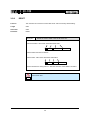
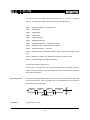
Byte to Byte Time
It means the delay time between bytes when Instruction Packet is transmitted. When this
time exceeds 100msec, EX-106 considers there is a transmission error and waits the
header (0xff 0xff) of packet again.
0xFF
0xFF
ID
Byte To Byte Time
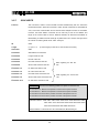
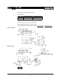
Connector
Company Name : Molex
48
Length
EX-106
Pin Number: 4 (or 5 for Optional VCC 5V)
Model Number
Male
Female
Molex Part Number
22-03-5045
50-37-5043
Old Part Number
5267-04
5264-04
Temperature range : -40°C to +105°C
Contact Insertion Force-max : 14.7N (3.30 lb)
Contact Retention Force-min : 14.7N (3.30 lb)
For further information, please visit the website www.molex.com or www.molex.co.jp.
Female Connector
Male Connector
Pin No.1
49
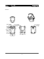
EX-106
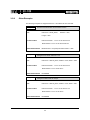
Dimension
50