1
Wi-HTest: Compliance Test Tool for Real-Time WirelessHARTTM Mesh
Network Devices
Song Han∗ , Jianping Song∗ , Xiuming Zhu∗ , Aloysius K. Mok∗ , Deji Chen† , Mark Nixon†
Wally Pratt‡ , Veena Gondhalekar‡
∗
Department of Computer Science, The University of Texas at Austin, Austin, TX 78712, USA
†
‡
{shan, sjp, xmzhu, mok}@cs.utexas.edu
Emerson Process Management, 12301 Research Blvd., Bldg. III, Austin, TX 78759, USA
{deji.chen, mark.nixon}@emerson.com
HART Communication Foundation, 9390 Research Blvd., Suite I-350, Austin TX 78759, USA
{wallyp, veenag}@hartcomm.org
Abstract— WirelessHARTTM was released in September 2007
and became IEC standard in April 2010 (IEC 62591). It is the
first open wireless communication standard specifically designed
for real-time process control applications. It is designed to
the same standard as its wired counterpart for reliability and
interoperability. To ensure the compliance with the HARTTM
Communication Protocol and the adherence to its strict timing
requirements, all WirelessHART devices must be thoroughly
tested and registered with the HART Communication Foundation
(HCF). In this paper, we present Wi-HTest, the test suite
developed to exercise WirelessHART devices, thus facilitating
compliance assessment. We discuss the detailed architecture of
Wi-HTest and highlight several critical features like packet handling with accurate timing control, fault data injection, and the
virtual network approach for scalable test setup. We also describe
a sniffer called Wi-Analys for capturing WirelessHART packets
along with their timing information and a post process suite
for analyzing the packets. These three tools together provide the
complete compliance verification environment for WirelessHART.
Based on the test specification developed by HCF, we presented
several representative test cases for examining WirelessHART
devices’ behaviors in different layers. These test cases in turn
show that Wi-HTest is a novel and efficient test suite for verifying
the compliance of WirelessHART devices.
I. I NTRODUCTION
Wireless technology has been regarded as a paradigm
shifter in the process industry and has received extensive
studies recently [2], [3], [4], [5], [6], [7], [8], [9], [10],
[11]. Compared to traditional wired process control systems,
their wireless counterparts have obvious advantages in easier
installation, more flexible configuration and lower maintenance cost. However, different from office or manufacturing
automation applications, industrial control systems have much
stricter timing requirements and higher security concerns. To
address these problems, WirelessHART [12] was officially
released in September 2007 as the first open wireless communication standard specifically designed for real-time process
control applications. In 2010 it became an IEC (International Electrotechnical Commission) standard, the IEC 62591.
WirelessHART is a secure and TDMA-based wireless mesh
0 An
earlier version of this paper appeared in [1].
networking technology operating in the 2.4 GHz ISM radio
band. It is designed with strict timing requirements and to be
highly reliable and interoperable while being easy to install
and operate. WirelessHART was engineered to strike a careful
balance between cost, simplicity, battery-life and guaranteed
real-time wireless communication.
To assure the standard compliance of HART products
(including WirelessHART devices), which is key to vendors’
success in the market and help them avoid expensive product
recalls and technical support costs, since 1995 the HART
Communication Foundation (HCF) [13] has operated a rigorous quality assurance program and all HART devices must
be thoroughly tested and registered with the HCF. As part
of this program, HCF develops detailed test specifications
and test tools for HART standards. Along with the release
of WirelessHART standard, HCF has developed Wi-HTest, an
extension of the original HTest tool to support WirelessHART
quality assurance especially focusing on the timing compliance
test.1 HCF has also developed a specific sniffer called WiAnalys for real-time monitoring of the WirelessHART network
and is working on a post process suite for analyzing the packets captured by Wi-Analys and generating the final compliance
report. All these three tools together provide a complete compliance verification environment for WirelessHART devices.
As a test suite specifically designed for wireless real-time
communication protocol, Wi-HTest has two inherent functionalities. First, it is able to construct the test packets in realtime manner and send them to the DUT (Device Under Test)
through 802.15.4 radio with accurate timing; Second, with
the help of Wi-Analys, Wi-HTest can capture the response
packets from the DUT along with its timing information. These
two functionalities enable Wi-HTest to not only check the
correctness of the response data but also verify its timing
information.
Wi-HTest aims at automating the execution of test cases
defined in the WirelessHART test specification. More specif1 The product name of Wi-HTest is HCF KIT-193. it could be purchased
from HCF.
ically, Wi-HTest provides the stimulus (good and bad) necessary to exercise operations of the DUT. The test cases
for verifying the compliance of WirelessHART devices can
be roughly classified into three different test scenarios, the
device join process, MAC layer data communication and
network layer data communication. In the join process, WiHTest coordinates with the DUT through a sequence of
message exchanges and verifies whether the DUT can join
the WirelessHART network successfully; In the MAC layer
communication tests, Wi-HTest transmits either correct data
packets or manipulate the packets by injecting fault data.
By evaluating DUT’s corresponding response including the
precise timing information, the DUT’s MAC layer compliance can be assessed. Wi-HTest conducts the network layer
communication tests by introducing the concept of virtual
network and virtual devices. It simulates a WirelessHART
network by adding necessary virtual devices and configuring
the communication schedules between the DUT and virtual
devices or among virtual devices. End-to-end communications
are executed by Wi-HTest to evaluate the DUT’s network
layer compliance by comparing its practical behaviors with the
standard ones according to the WirelessHART specification.
In this paper, we discuss the detailed design of Wi-HTest
and describe the other two important tools: the Wi-Analys and
the post process suite. Based on these three tools, we present
several representative test cases to demonstrate the efficiency
of our test suite. To the best of our knowledge, this is the
first reported effort to build a commercial-grade test suite for
WirelessHART standard. Our contributions in this paper are
fourfold:
•
•
•
•
Introduction of WirelessHART test specification and
test script. We describe the WirelessHART test specification and present the general format of the test scripts.
Description of the architecture of Wi-HTest. We
present the Wi-HTest architecture and highlight the design of several critical features in Wi-HTest. For example, the generation of test packets with accurate timing
control, the packet manipulation and the virtual network
approach. We also share our first-hand experience in
designing and implementing these critical features.
Description of Wi-Analys and the post process suite.
We describe the real-time capturing and analyzing features in Wi-Analys and the post process suite.
Demonstration of representative test cases. These test
cases demonstrate how Wi-HTest, Wi-Analys and the post
process suite work together to assess the compliance of
the DUT in different communication layers.
The remainder of this paper is organized as follows. In
Section II, we introduce the WirelessHART standard and some
existing test suites designed for public wireless standards
in office and manufacturing automation. Section III presents
the WirelessHART test specification and the structure of the
test script. We describe the detailed design of Wi-HTest in
Section IV. Section V discusses the functionalities of WiAnalys and the post process suite. Section VI presents several
representative test cases and discusses the advantages and limitations of the virtual network approach. Section VII shares the
broad lessons we learnt from the design and implementation
of Wi-HTest. We conclude the paper in Section VIII.
II. BACKGROUND AND R ELATED W ORKS
To help vendors assure product interoperability and shorten
the time to market, many test suites are available in the market
for various wireless standards, such as Bluetooth [14], ZigBee [15], and Wi-Fi [16]. In this section, we first give a brief
introduction of the WirelessHART standard and then discuss
several existing test suites for well-known wireless standards.
We also describe HTest, the test suite designed for wired
HART communication protocols. Wi-HTest is an extension of
HTest to support WirelessHART quality assurance.
A. WirelessHART Architecture
Traditional wireless standards for office and manufacturing
automation cannot meet the stringent timing and security
requirements of industrial control. WirelessHART standard is
specifically targeted to solve these problems and provide a
complete solution for real-time process control applications.
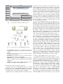
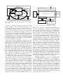
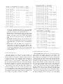
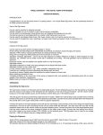
Figure 1 illustrates the architecture of the HART protocol
according to the OSI 7-layer communication model. As a
part of the HART protocol, the architecture of WirelessHART
protocol is shown on the right side of Fig. 1. At the very
bottom of the protocol, WirelessHART adopts IEEE 802.15.42006 [17] as the physical layer. On top of that, WirelessHART
defines its own time-synchronized data link layer. Some notable features of WirelessHART data link layer include strict
10ms time slot, network wide time synchronization, channel
hopping, channel blacklisting, and industry-standard AES-128
ciphers and keys. The network layer supports self-organizing
and self-healing mesh networking techniques using source
routing and graph routing. In this way, messages can be routed
around interferences and obstacles, which greatly improves
the network performance in noisy and harsh environments.
WirelessHART also distinguishes itself from other public
standards by maintaining a central Network Manager. The
Network Manager is responsible for maintaining up-to-date
routes and communication schedules for the network, thus
guaranteeing the real-time network communications.
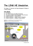
A typical topology of a WirelessHART mesh network is
presented in Fig. 2. All WirelessHART devices support the
basic mesh node functionalities, including routing capability.
The basic device types of a WirelessHART network are listed
as follows.
•
•
Network Manager is responsible for configuring the network, scheduling and managing communication among
WirelessHART devices. It is implemented as a software
that resides in the Gateway or the Host.
Gateway connects Host applications with the field devices. There is one Gateway per one WirelessHART
network.
OSI Layer
Application
HART
Command Oriented. Predefined Data Types and
Application Procedures
Presentation
Session
Transport
Auto-Segmented transfer of large data sets, reliable
stream transport, Negotiated Segment sizes
Power-Optimized Redundant Path,
Mesh to the edge Network
Network
Data Link
A Binary, Byte Oriented, Token
Passing, Master/Slave Protocol
Secure, Time Synched TDMA/
CSMA, Frequency Agile with ARQ
Physical
Simultaneous Analog & Digital
Signaling 4-20mA Copper Wiring
2.4 GHz Wireless, 802.15.4 based
radios, 10dBm Tx Power
Wired FSK/PSK & RS 485
Fig. 1.
Fig. 2.
•
•
•
•
•
Wireless 2.4 GHz
The architecture of HART communication protocol
A typical topology of a WirelessHART mesh network
Access Point is attached to the Gateway and provides
redundant paths between the wireless network and the
Gateway.
Router is deployed in the network to improve network
coverage and connectivity.
Field Device is attached to the process plant and collects
data. It could be a sensor or an actuator.
Handheld is a portable WirelessHART-enabled computer
used to configure devices, run diagnostics, and perform
calibrations.
Adapter is a bridge device between the wireless mesh
network and traditional wired HART devices.
B. Existing Test Suites for Wireless Standards
Although to the best of our knowledge, there is no existing
test suite designed for WirelessHART standard, many testing
and analyzing tools are available for evaluating the compliance
of the DUTs with several existing wireless standards.
ZigBee aCT [18] is a ZigBee automated compliance testing
solution that executes a sequence of Tx and Rx tests to characterize a DUT’s compliance and performance in accordance
with the IEEE 802.15.4 standard and generates detailed test
reports. The main advantage of this solution includes test
automation with minimal user input and the ability to save test
results in easy-to-read report formats. ZigBee aCT performs
several compliance tests on any or all of the 16 frequency
channels numbered from 11 to 26. However, ZigBee aCT only
focuses on a DUT’s compliance in the MAC layer and lacks
a thorough test of its network layer behavior. Also, there is
no way for the users to inject any fault data thus it is difficult
if not impossible to test its corresponding behaviors in the
presence of ill-behaved stimuli.
Codenomicon Robustness Tester [19] for Bluetooth is a
black-box testing product with ready-made Bluetooth test
cases. The tests verify how well an implementation can withstand invalid and malformed traffic, thus resulting in improved
product stability and security. The Codenomicon tester consists
of a set of separate test suites, each of which tests a particular
Bluetooth protocol layer or profile and all relevant protocols
and profiles of Bluetooth are covered. The tests have been
designed in accordance with Bluetooth Core specification 2.0
where applicable, but implementations based on any earlier
versions of the specification may still be tested as well.
To ensure industry wide ubiquitous Wi-Fi, the Wi-Fi Alliance [20] proposes a certification program which includes a
series of standardized interoperability tests. The Alliance has
two approved standard test methodologies for Wi-Fi Certification: the original Wi-Fi certification methodology designed
for PCs and Access Points and the new Wi-Fi Alliance test
engine methodology which is targeted at application specific
devices with embedded Wi-Fi connectivity. Among various
test suites developed for Wi-Fi certification, the AzCert WiFi certification test suite [21] is a semi-automated solution
used by Wi-Fi Alliance authorized test laboratories. This
solution enables users to reduce the learning curve and ongoing resources required for certification testing; reduce time
spent on executing the Wi-Fi Alliance test plan; generate
customized test stimuli using the Wi-Fi Traffic Generator
(WTG); debug by running full test or specific test steps, and
interpret information using detailed test results reporting.
C. HTest for Wired HART Communication Protocols
The HART Communication Foundation (HCF) is an independent, not-for-profit organization owning and managing all
elements of HART technology. HCF tests the compliance of
wired HART products using HTest which is a general purpose
HART master software for PC with HART modem. HTest
uses CINT [22], a simple interpreted script language to build,
send, receive and display HART messages. By evaluating
the correctness of the response data, the compliance of the
DUT can be verified. With the release of WirelessHART
standard and rapid emergence of WirelessHART devices in
the market, it is necessary for the HCF to extend HTest to
support wireless commands testing and assure the compliance
of WirelessHART devices. The following of this paper will
elaborate our effort of designing and implementing Wi-HTest
to achieve this goal.
III. W IRELESS HART TEST SPECIFICATION AND TEST
SCRIPTS
A. Test Specification Overview
In developing a WirelessHART compatible field device, a
variety of informal ad-hoc testing and formal tests are to
be performed. HCF simplifies this test effort by supplying
a test specification [23] for developers. All tests must be
completed along with the test report prior to product release
and product registration with HCF. The test specification
provides clear test requirements and reduces the number of
test plans that must be developed by the manufacturer. They
can be used early in the development effort to informally verify
functionality during implementation and are a useful part of a
regression testing program as the field device is maintained and
enhanced. Further, the test specification clarifies ambiguities
in the protocol and is the final, definitive authority when
interpreting the protocol.
This test specification uses a quasi “black box” approach
to confirming compliance with WirelessHART standard. The
complete set of tests consists of the following five phases and
each phase contains multiple test descriptions that are intended
for sequential execution.
• Boot-strap tests
• Single correspondent tests
• Multiple correspondent tests
• Multi-channel-selection tests
• Stress tests
The Boot-strap tests try to perform an audit of the command
set implemented in the DUT through either maintenance port
or wireless connection. They also set the DUT in an initialized
state and test its join process into a specific WirelessHART
network.
Based on the successful completion of all Boot-Strap tests,
the single correspondent tests focus on a single logical RF
channel and the DUT interacts directly with a Network Manager and Gateway. This series of tests examine that a wireless field device properly requests admission to the wireless
network; accepts commands that condition its operation in
the wireless network, including commands with a deferred
execution; and operates synchronously with the peer device.
Different from the single correspondent tests, multiple correspondent tests verify that a wireless device properly interacts
with multiple peers, including inferring information about
those peers from received messages.
Multi-channel-selection tests extend the multiple correspondent tests by ensuring that a wireless device properly selects
among multiple potential channels on which its schedule
permits operation.
Finally, the stress tests combine all the prior tests into a
single random sequence that serves to examine continuous device operations in a simulated field environment. The primary
purpose of this phase is to confirm that the device will reliably
interoperate with one another in a real-world environment.
B. WirelessHART Test Script
According to the WirelessHART test specification, we have
written the test scripts for various test cases in each test phase.
HCF also provides a script development manual [24] for the
ease of the developers. Test scripts are small, narrowly-focused
test applications. They are taken as input to feed in the WiHTest for establishing the test environments, generating proper
test packets and conducting the compliance tests. Typically a
test script includes two parts: The test configuration and the
test body. The test configuration section initializes the Network
Manager and Gateway, configures the Wi-Analys and sets up
the RF Interface and various test parameters. Necessary virtual
devices and corresponding communication schedules are also
added to support network layer compliance tests. The test
body is consisted of a sequence of small test steps. Each test
step generates or manipulates a WirelessHART data packet
by calling related libraries implemented in Wi-HTest. The test
body then waits for the response from the DUT and verifies its
compliance. The test script is written in C++ and the pseudo
code of the test script for device join is presented in the
Appendix. Readers are referred to the test specification for
other concrete examples.
IV. W I -HT EST ARCHITECTURE
A. Overview
Wi-HTest extends HTest by supporting wireless commands
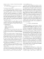
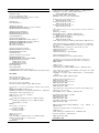
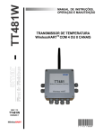
to test WirelessHART-enabled devices. Figure 3 shows the
actual hardware in the Wi-HTest test suite and the software
architecture is depicted in Figure 4. Wi-HTest consists of two
components: the Wi-HTest Host and a RF Interface. The WiHTest Host is responsible for overall control and execution
of the input test scripts. It first configure the DUT with
necessary information including the network ID, and the join
key through the FSK modem. After that, according to the specific requirements of the scripts, the Wi-HTest Host generates
either correct packets or manipulates the packets by injecting
fault data into either the command payload or the headers
of different layers. Wi-HTest Host then sends these packets
to the RF Interface for transmission through the 802.15.4
radio. The RF Interface is a compact WirelessHART stack.
It is responsible for low-level, time-critical communications
to and from the DUT using its onboard wireless transceiver.
Responses from DUT are forwarded back to the Wi-HTest
Host and are also captured by Wi-Analys for post processing.
Finally, the post process suite reads in the log recorded by
Wi-Analys (especially the timing information of the response
packets) and generates the corresponding compliance report
for the DUT. The details of the system design of Wi-HTest
are discussed in the following sections.
B. Wi-HTest Host Architecture
The Wi-HTest Host is implemented on a Linux system
(shown on the left in Figure 3) and consists of three major
modules: the RF Interface driver, network layer library, and
the Wi-HTest engine. The architecture of the Wi-HTest Host
is depicted in Figure 5. These modules coordinate closely
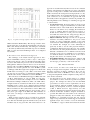
Byte
0-4
5
6
7
7.6-7.7
7.0-7.5
8-9
10-n
(n+1)-(n+2)
Format
Unsigned-8
Unsigned-8
Unsigned-8
Bits-8
Enum-2
Bits-6
Unsigned-16
Unsigned
Unsigned-16
Description
Preamble (0xFF)
Delimiter (0x86)
Frame length (exclude itself)
Frame Control
Normal Data (0) Acknowledge(3)
Frame counter
Command Number
Command Data
CCITT CRC-16
TABLE I
Frame format of the protocol between Host and the RF Interface
Fig. 3.
FSKModem
An overview of Wi-HTest system
W-iHTestHost
HTestEngni e
LniuxSystem
USBConneco
ti n
DUT
Fig. 4.
E
I EE802.15.4
Radoi
RFInterface
The high level architecture of Wi-HTest
to achieve the following functionalities: 1) Read the test
scripts as input and set up corresponding equipments and
test environments; 2) According to the requirements of the
test script, generate corresponding command payload and
assemble it with proper network layer header. If necessary,
inject designated errors into the network packet and further
inform the data link layer and physical layer in which fields
and how their headers should be manipulated. 3) Transmit the
control information and data packets to the MAC layer for
transmission and wait for the response from the DUT. Next
we shall describe the details of each module.
1) RF Interface driver: The driver between the Wi-HTest
Host and the RF Interface uses a simple private protocol for
communication through USB. The protocol provides basic
framing functions, such as preambles, delimiter, frame control
and CRC error detection. The frame format of the protocol is
shown in Table I.
There are three types of commands carried over the USB
cable: commands from the Host2 to configure the RF Interface
(Type I), commands to relay data packets between the WiHTest Host and the DUT (Type II), and commands from the
RF Interface to the Wi-HTest Host to update certain data
structure in the Host (Type III).
support the virtual device. For example, Command 967 is used
by the Host to add a link assignment to the RF interface and
Command 64521 further supports to add any link among the
RF Interface, the virtual devices and the DUT. We will present
the details of the virtual device in Section IV-B.2.
Type II: There is only one Type II command, Command
64513 defined to denote the data request from the network
layer to the data link layer3 or the data indication from the
data link layer to the network layer. The data request message
from the network layer to the data link layer contains a special
header and the network layer payload. This header includes a
bitstring indicating if and which MAC or physical header field
should be manipulated to transmit false messages. The details
of the packet manipulation in Wi-HTest will be discussed in
Section IV-B.2.
Type III: Currently there is only one Type III command,
command 64518, used by the RF Interface to update its ASN
(Absolute Slot Number) to the Wi-HTest Host. This provides
Wi-HTest Host a rough ASN snippet to fill in the network
layer header. More Type III commands are to be introduced
to provide the data sharing between the Host and the RF
Interface.
The frame counter field guarantees the reliable communication between the Wi-HTest Host and RF Interface. Each end
of the communication keeps two frame counters, one for itself
and one for the other end. Each time it sends a frame, its own
frame counter is incremented by one. When it receives a frame,
the counter in the incoming frame is compared to the frame
counter for the sender. If they are equal, the frame is expected.
Otherwise, the frame is discarded silently. Whenever a correct
frame is received, the receiver increments the frame counter
for the sender by one.
Type I: Basically, Type I commands are mostly WirelessHART commands and are used to configure the RF Interface. However, these commands are further extended to
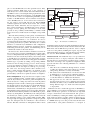
2) The network layer library in Wi-HTest Host: The
network layer is constructed as a library along with an
independent receiving thread in Wi-HTest Host. The network
layer library provides function calls to construct or manipulate
the data payload and packet header while the receiving thread
handles the response packet back from the MAC layer or
processes received unsolicited messages.
We separate the network layer from the RF interface and
2 In the following of the paper, we use “Host” and “Wi-HTest Host”
interchangeably.
3 In the following of the paper, we use “data link layer” and “MAC layer”
interchangeably.
Packet Manipulation: To provide the tester complete control
over the transmitted packet, a critical feature provided by the
network layer library is the bitwise packet manipulation. It
allows the testers to change any field of the network packets
including the header and the command payload. Furthermore,
the interface between the network layer and the RF Interface
(Command 64513 in Section IV-B.1) enables us to specify
which fields of the MAC layer and physical layer header will
be manipulated using a bitstring and corresponding data fields.
The first bit in the bitstring indicates if it is MAC (0) or physical layer (1) manipulation. For MAC layer the subsequent bits
are the first byte, address specifier, sequence number, network
ID, destination address, source address, PDU specifier, MIC,
message length and applying superframe routing. For physical
layer the subsequent bits are transmission offset and fixed
timeslot. Bit value of 0 means no manipulation while 1 means
Test Scripts
Initialization,MSG formatting
Network
Network
Layer Lib
Layer Lib
Other
Other
Libs
Libs
Incoming MSG
Incoming MSG
Processor
Processor
Update
Virtual
Network
Transmit
Transmit
Wi-HTest Engine
Wi-HTest Engine
Network
Network
Manager
Manager
Receive
Receive
MSG Queue
MSG Queue
RF Interface Communications Driver
RF Interface Communications Driver
Wi-HTest on Linux
Wi-HTest on Linux
System
System
USB
USB
put it on the Wi-HTest Host for three practical reasons. First,
compared with the MAC layer, most of the operations on
network layer are not time critical. Given the limited memory
and MCU resources, and stringent timing requirements on the
RF Interface, putting the network layer on the Wi-HTest Host
can save more resources for implementing Wi-HTest-specific
modules on the RF Interface; Second, with the network layer
on the Wi-HTest Host, it is more direct and convenient for
the test scripts to inject fault data into the WirelessHART
command payload, the network layer header, and even the
MAC layer header. Otherwise, the test script has to convey
these control information to the RF through various interface
messages; At last, putting the network layer on the Host
provides us the possibility and flexibility to simulate virtual
devices and form a virtual network for multiple correspondent
tests.
The network layer library provides plenty of useful function
calls for supporting various network operations. For example,
based on given parameters, a set of functions are used to
construct network header while another function set is for parsing existing network layer packets. The library also contains
functions for network layer initialization and configuration,
building interface messages, enciphering, deciphering and authenticating network layer packets, and maintaining various
communication tables in the network layer.
In each test case, when a transmit command is read in from
the test script, the test engine in Wi-HTest Host formats either
correct or manipulated network layer packets by calling related
functions from the network layer library and forwards them
to the RF driver for transmission; the independent receiving
thread continuously monitors the incoming queue and handles
different types of packets by calling corresponding callback
functions in the incoming message processor. If the message
is a response that the test engine is waiting for, it is stored in a
shared buffer and the test engine is woken up for processing.
For other cases, the message will be either discarded or be
used to update relevant data structures. An example of such
messages is the neighbor health report which is generated
periodically by each device to update its status to its neighbors.
DUT
DUT
Fig. 5.
IEEE802.15.4Radio
IEEE802.15.4Radio
RF Interface
RF Interface
The architecture of Wi-HTest Host
manipulated value should be used. The manipulation functions
in the network layer library and the interface between the WiHTest Host and the RF Board provide the testers complete
control over the packets (including the request, response and
acknowledgement messages), and help them design arbitrary
test cases for WirelessHART compliance evaluation.
Virtual Network: The traditional way to set up a testbed for
network layer tests is to deploy exactly the same number of
physical devices as needed in the experiment, and to configure
each device according to the experiment configuration. This
approach introduces the following difficulties for a wireless
mesh testbed:
•
•
•
•
Since the nodes communicate through wireless, we have
to make sure that the nodes in the testbed are communicating among themselves correctly and reliably.
The testbed can contain hundreds of nodes and it would
be difficult just to set it up before putting the DUT in.
It is a challenge to tell a physical node to misbehave in
a controlled manner to simulate the interference.
The approach does not scale. For different test cases,
the physical devices have to be configured and organized
differently. It will be costly to maintain different testbeds
during different stages of a mesh network development
or deployment.
Different from the conventional approach, in Wi-HTest, to
support multiple correspondent tests which focus on evaluating
DUT’s network layer operations, we introduce two important
concepts: virtual device and virtual network. Our goal is to
achieve scalability by reducing the number of physical devices
in the testbed as much as possible, and this is achieved by using the same antenna for multiple purposes. As WirelessHART
is a TDMA-based protocol and provides network-wide time
synchronization, each packet transmission or reception is
Test Scripts
Test Scripts
Wi-HTest
Simulated MAC Packet
Simulated MAC Packet
Gateway
Self-ACK
Virtual
Device
1
MAC
Packet
Virtual
Device
2
Network Manager
Configuration
Expected
ACK
Wi-HTest Test Engine
Wi-HTest Test Engine
Self-ACK
Configuration
IEEE8021
. 54
.
Radio
Configuration
MAC
ACK
User Interface
User Interface
Network
Network
Manager
Manager
Application Layer Library
Application Layer Library
Expected
Relay
Sending Buffer
Sending Buffer
Network
Network
Layer
Layer
Libary
Libary
Receiving Buffer
Receiving Buffer
DUT
Fig. 6. An example of source routing among Gateway, two virtual devices
and the DUT
conducted in a dedicated timeslot with a fixed time offset.
We take advantage of this accurate timing information in our
virtual network approach: whenever a physical device tries
to communication with the DUT on channel c at timeslot t,
we choose the antenna that represents the same channel and
perform the same communication at timeslot t. In this way, a
set of virtual devices can replace the physical devices and form
a virtual network for the DUT by carefully configuring their
routing information and communication schedules. This makes
the DUT believe that it is operating in a real WirelessHART
network with multiple devices and then various network layer
tests can be performed on the device.
Following the design of Wi-HTest, the virtual device also
splits its network and MAC layer, and installs them on the
Wi-HTest Host and the RF Interface respectively. Although
physically all virtual devices’ network layers reside on the
same Wi-HTest Host, the Network Manager will allocate an
independent session and corresponding table structures for
each virtual device. Similar to the communication between
the Gateway and the DUT, with the help of the network layer
library, the tester will have complete control over the network
layer communication between the Gateway and the virtual
device. The tester can manipulate every field of the network
header and payload to fulfil various testing purposes.
The MAC layer design of the virtual device is relatively
more complex. To support virtual devices, the Network Manager will first configure the RF Interface through Type I
command. It will allocate necessary superframes and links
to satisfy the communication requirements. The configuration
varies according to different test scenarios. In the multiple
correspondent test phase, each test case has a pre-determined
communication sequence among the Gateway, multiple virtual
devices and the DUT. If the MAC communication is between
the Gateway and the virtual device or between two virtual
devices, the tester will first generate the packet with correct
source and destination addresses in the MAC header. This
packet will be transmitted on a dedicated link configured by
the Network Manager and selected by the link scheduler. To
completely conform to the WirelessHART standard, a self-
RF Interface Driver
RF Interface Driver
Fig. 7.
Incoming MSG
Incoming MSG
Processor
Processor
The architecture of the Wi-HTest test engine
ACK will be constructed or manipulated immediately in this
case. The self-ACK will be transmitted on the same link with
precise timing. On the other hand, if the communication is
from Gateway/virtual device to the DUT, the testing packets
will be generated in the normal way and the RF Interface will
wait for the DUT’s response. Once the response is back, it will
be forwarded to the Wi-HTest Host for further processing.
Figure 6 illustrates a typical example of the communication
among the Gateway, the DUT and two virtual devices (VD1
and VD2). The Gateway initializes an end-to-end communication to VD2 by constructing the network packet using
the following source routing sequence: Gateway → VD1 →
DUT → VD2. The test script first generates and transmits the
MAC packet from the Gateway to VD1, the corresponding
self-ACK will be automatically generated by the RF board.
The test script will then go on constructing a normal MAC
packet from VD1 to DUT with the same network payload.
Under the fixed routing information, the DUT is expected to
acknowledge this transmission in the same time slot and relay
the network payload to VD2. After receiving the packet from
the DUT, VD2 will forward it to the Wi-HTest Host and finish
the compliance report. All these packets will be captured by
Wi-Analys with their accurate timing information. In this way,
a virtual WirelessHART mesh network is simulated.
3) Wi-HTest Test Engine: The heart of the Wi-HTest Host
is a test engine, whose architecture is shown in Figure 7.
The test engine is a C++ program executed in the CINT [22]
environment. CINT is a C/C++ interpreter aimed at processing
C/C++ scripts with reduced compile and link cycle. An
important component of the test engine is the application
layer library. Working together with the Network Manager
and the network layer library, this library provides a bunch of
supporting functions through the user interface to help testers
generate various test scripts. These scripts implement the
specific requirements of the test case by calling corresponding
functions in the library. This working mechanism results in our
rapid development of various test cases.
•
Wi-HTest Host
Wi-HTest Host
FSK Communication (send/receive)
FSK Communication (send/receive)
USB Connection
USB Connection
DUT
DUT
Host Communications Driver
Host Communications Driver
Cmd Processors
Cmd Processors
PIB
PIB
Data Link Layer
Data Link Layer
IEEE 802.15.4 Radio
IEEE 802.15.4 Radio
Physical Layer
Physical Layer
RF Interface
RF Interface
Fig. 8.
The architecture of the RF Interface in Wi-HTest
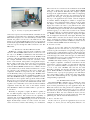
Fig. 9.
Freescale JM128 Evaluation Board
The main functionality of the test engine is to read in the
test scripts and generate corresponding wireless commands for
the DUT. It then passes the commands through the network
layer, assembles it with required header, and sends it to the
RF Interface. The test engine then waits for the response
from the DUT, puts it in the receiving buffer and verifies its
correctness. On the other hand, the test engine will maintain
timers for various timeout defined in the test script. If a timeout
is triggered while no expected response is received from the
DUT, the test engine will report corresponding error messages.
C. RF Interface Design
For the Wi-HTest Host to be able to talk to the DUT
following the WirelessHART protocol, we connect the RF
Interface through a USB cable to the Host. The RF Interface
works as an Access Point between the Wi-HTest Host and the
DUT. Figure 8 illustrates the overall architecture of the RF
Interface.
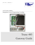
1) Hardware Platform: We implement the RF Interface on
the EVBJM128 [25] toolkit from Freescale which is shown
in Figure 9. This toolkit has the following features and is
powerful enough to meet the stringent timing requirements
defined in the WirelessHART specification.
• Up to 50.33 MHz ColdFire [26] V1 core.
•
•
•
•
Up to 128 KB of flash memory and up to 16K RAM with
security circuit.
Supports four low-power modes.
On-board logic analyzer and virtual serial port.
USB device mode and host mode support with Mini-AB
USB connector.
8 user LEDs and 5 push buttons.
2) Real-time Embedded Compact Stack: The data link
layer and physical layer on the RF Interface are collectively
called the Compact Stack as the network layer is separated
and put on the Wi-HTest Host. The compact stack is fully
compliant with the WirelessHART specification, which means
it must meet the stringent timing requirements defined in the
specification. To address this strict time synchronization issue,
as we discussed in [3], we proposed several solutions.
First of all, enciphering a frame and deciphering its acknowledgement (using AES-128 [27]) can take the stack
out of synchronization. In order to speed up the enciphering/deciphering process, we take a streaming strategy. For
example, if it is in a receiving slot, the stack starts to decipher
the incoming frame when the first 16 bytes are received. In this
way, the calculation intensive security checking can always
be finished in time. Secondly, the interrupt handler is kept as
simple as possible. Only those time critical jobs are put in
the handler. Non-time-critical jobs are deferred and would be
processed at appropriate time. Thirdly, we give the MAC layer
the highest scheduling priority. Every time there is a frame to
be processed, the MAC layer can preempt all the other tasks
and get the MCU. There could be several jobs awaiting at
any time in the MAC layer. We further prioritize these jobs to
keep the stack in synchronization. For instance, transmitting a
frame has priority over accepting a frame from the command
processor.
For the limit of space, interested readers are referred to [3]
for the details of the stack implementation.
3) The Command Processor: As the RF interface is basically a wireless Access Point for the Wi-HTest Host, all test
commands are transmitted via it and all test responses are
captured by the RF Interface. All commands and responses
are handled in the command processor, and there can be four
types of messages carried on the USB cable:
• Board configuration commands: These commands are
issued by the Host to configure the RF Interface.
• Test commands: These commands are issued by the Host
to be transmitted by the RF Interface to the DUT.
• Test responses: They are responses from the DUT to the
Host.
• Board updates: They are updates from the RF Interface
to the Host.
We use the simple communication protocol defined in
Section IV-B.1 to differentiate the messages and provide error
detection and retries. During initialization, the RF Interface
waits for configuration commands from the Host. After it is
set up properly, the RF Interface can accept test commands
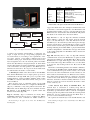
Fig. 10.
Wi-Analys for capturing WirelessHART traffic
and receive responses from the DUT. If the commands are test
commands, it encapsulates the command in a WirelessHART
MAC frame and passes it to the data link layer, which would
transmit the packet over the air to the DUT. In the other
direction, every time the RF interface receives a response from
the DUT (through the PHY and MAC layers), the RF Interface
sends the response through the USB connection to the WiHTest Host.
V. W I -A NALYS AND P OST P ROCESS S UITE
Wi-HTest is a critical component in the compliance verification for WirelessHART-enabled devices, however it is not
the only tool. Wi-HTest communicates with the DUT as if
the DUT lives in a WirelessHART network. Wi-HTest itself
could not collect all compliance information about the device.
For example, Wi-HTest could verify the correctness of the
device on the network, transportation, and application layers.
But it could not tell if the device uses the correct message
retry algorithm and whether the strict timing requirements
defined in WirelessHART standard are met. A DUT conforms
to the standard only if all its wireless transmissions over the
air conform to the standard. For this reason, another two
compliance verification components are also essential. They
are the Wi-Analys and a post processing suite. Wi-HTest is the
instigator that generates all the communication traffic in realtime. The HART Wi-Analys compliance verification receiver,
Wi-Analys for short, captures and logs all the wireless traffic.
The logs are post-processed by the post process suite to check
if all the messages conform to the standard. The benefit of the
log files is two folded. They serve as the raw data for ultimate
compliance check; they also serve as the defense evidence
when Wi-HTest is blamed for DUT’s failure to pass the test.
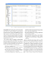
A. Wi-Analys
Wi-Analys is designed to capture all 802.15.4 packets in
the 2.4 GHz frequency range but focuses on those from
WirelessHART devices. The receiver has the capability of
capturing data on 16 WirelessHART channels simultaneously
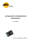
and at a speed of up to 1000 messages per second. As shown in
Figure 10, Wi-Analys consists of a radio receiver box at the
center front and a software suite running on a workstation.
The receiver box is connected to the workstation via the USB
cable. The software suite logs all captured WirelessHART
messages on all channels. Wi-Analys also displays captured
messages in an organized manner, either online or redisplaying
a captured log file. The messages are interpreted and the
fields in the messages, from physical layer fields all the
way up to the application layer fields, could be displayed
in columns. Further, intelligence is built-in to decipher the
messages so that enciphered fields could be shown in plain
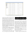
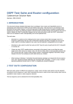
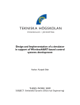
text. Figure 11 demonstrates a screen capture of Wi-Analys
display and readers can refer to [28] which has the same
picture in higher resolution. The figure shows a partial segment
of the DUT joining the network. We observe that in Figure 11
channel hopping is in effect and recorded in the channel
column. We could also see that the application layer messages,
i.e., HART commands and responses are displayed in plain
text. As displayed in the left side of the figure, Wi-Analys has
a built-in filter so that the user can narrow down the message
list by specifying the parsing conditions on each field. WiAnalys is a standalone product from HCF. It could be used as
a real-time WirelessHART network monitoring tool.
B. Post Process Suite
The post process suite judges the successfulness of the
compliance test. For each test case, a post process program
reads the log file and analyzes it. Depending on the purpose
of each test case, it will check the sequence of the messages the
DUT transmitted, the transmission time points, the relationship
of the messages, the content of the messages, etc. If all satisfy
the standard, the test case is passed. Otherwise the place where
the standard is violated will be reported.
Wi-HTest, Wi-Analys and the post process suite constitute
the complete compliance verification environment. In this
environment, a device typically goes through the following
steps to be certified by HCF. A complete test is composed
of a set of test cases. Wi-HTest runs each test case with
Wi-Analys capturing the messages through the whole test
period. While Wi-HTest could declare if the device passes
certain test cases. a post process program per case will analyze
the corresponding log file to check if the device has strictly
followed the standard during the test, especially satisfied the
stringent timing requirements.
VI. W I -HT EST T EST C ASES
The WirelessHART compliance test is divided into many
isolated test cases. They test the compliance of each protocol
layer, from the physical layer up to the application layer. WiHTest runs each test case and generates the compliance report
with the help from Wi-Analys and the post process suite. In
this section, we present several representative test cases for
demonstration. These test cases include the device join test,
superframe management test, network routing test, burst data
publishing test, and the network maintenance test.
A. Device Join Test Case
In this section we present an application layer test case
example, i.e., device join test. Among many functions of a
Fig. 11.
A segment of message sequence in the device join test case captured by Wi-Analys
WirelessHART network, device join is one of the most critical
and difficult processes. Any DUT must first join the network
before other tests could be performed on it. We will first
describe the join process in the WirelessHART network and
then demonstrate the complete test sequence in this test. The
DUT’s responses to each specific test step are captured by WiAnalys and kept in the log. We will study the log carefully
and focus on verifying the timing compliance of the response
packet, the successful synchronization between the Wi-HTest
and the DUT and the correct usage of various security keys
during the device join process.
An overview of the join sequence of a WirelessHART
device is shown in Figure 12. Wi-HTest plays the role of
the Gateway and has partial functionalities of the Network
Manager. The RF Interface works as the Access Point between
the Gateway and the WirelessHART network. The general
progression that must be followed for the joining device to
become operational includes the following 6 steps:
•
•
•
•
The device is configured with the network id and join
key through a maintenance tool.
The device listens for the network traffic to synchronize
to the network clock and identify potential parents.
The device then presents its credentials (including the
device’s identity and join key) to the Network Manager
to demonstrate that the device is trustworthy.
Once the Network Manager has scrutinized the device’s
•
•
credentials and deems the device trustworthy, it provides
the first session key and network key to the device. The
device is then in the quarantined state.
The Network Manager then proceeds to integrate the
device into the network by provisioning the device with
normal superframes and links.
Once the quarantined device obtains a session with the
Gateway it becomes operational. It then begins acquiring
the bandwidth and communication resources required
to publish process data and events as dictated by its
configuration.
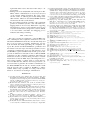
Figure 11 demonstrates the message segment of a DUT
joining the network. To make the figure more compact, we
removed most of the advertisement messages from the WiAnalys log. After reading in the test script for device join
test, Wi-HTest first configures the RF Interface by writing
superframes and corresponding links using command 965.
After receiving the configuration information, the RF Interface starts to broadcast advertisements periodically twice per
second. On the DUT side, upon powered up, it keeps listening
for WirelessHART advertisement messages, one channel at a
time. It keeps the information in the advisement messages
from any device it could hear from. Once the DUT has heard
from Wi-HTest and decides to join, it sends out the join
request message, which is shown as message number 732 in
Figure 11. The join request contains the device information
Man
ie
tnanceTool
Jon
in
i gDevci e
Wi-HTest
Wrte
i Joni Key
ACK-Joni Key
Wrte
i NetD
I
ACK-NetD
I
nIa
ti teJoni
ACK-nIa
ti teJoni
Adverstie
LsitenMode
Joni Request
AuthenctiateJoni Key
Aol cateSessoi nKey
Wrte
i Key
ACK-Wrte
i Key
Monto
i rJoni
Wrte
i framen,ilks
ACK-Monto
i rJoni
ACK-Wrte
i framesn,ilks
Negi hborReport
ACK-Negi bhorReport
Figure 11 does show that the DUT constructs the join
request and various response messages with correct command
payloads and uses proper keys for network layer and MAC
layer encryption and decryption. However, this is not sufficient
to assert that the DUT has completely passed the device join
compliance test. To claim that the DUT is fully compliant
to the WirelessHART standard, the timing between the data
request message and the corresponding ACK must be carefully
measured. As we have shown in [3], Figure 13 depicts the
specific timing requirement inside a WirelessHART time slot
(10ms) and a receiver must acknowledge a packet within
TsTxAckDelay time units after the end of the current message.
This duration could vary within ±100µs as is defined by
the data link layer specification. By carefully evaluating the
timestamps of the data request message and its corresponding
ACK captured and recorded by Wi-Analys, we can see that
their timing do not deviate more than 100µs. This thus finally
certificates the complete compliance of the DUT with the
WirelessHART standard.
B. Superframe Management Test Case
Fig. 12.
The join sequence in WirelessHART standard
TsCCAOffset
TsCCA
TsRxTx
TsRxOffset
TsError
TsRxOffset
TsMaxPacket
TsRxAckDelay
TsAckWait
TsRxOffset
Fig. 13.
TsTxAckDelay
TsAck
The slot timing in WirelessHART standard
that is enciphered with the join key. In Figure 11, Wi-Analys
deciphers the message and displays the device information in
the network payload column. Wi-HTest uses the join key for
decryption and verifies the correctness of the join request.
It then sends out the join reply to the DUT, the message
number 751. The join reply includes network information such
as the network key, the assigned two-byte nickname and the
session key. From then on, the Wi-HTest and the DUT will
use the session key for network layer encryption instead of the
join key. They will also use the network key for MAC layer
enciphering. After successfully processing the join reply, the
DUT sends back a confirmation message, number 754. Notice
here in packet 754, we have the observation that the DUT
is already using the assigned nickname while not the 8-byte
long address for communication and the network layer payload
can be deciphered successfully using the specific session
key. Wi-HTest then sends out more information including
the superframes and links to configure the DUT in message
number 855, which is then confirmed by the DUT with
message number 877. From this point on the DUT has joined
the network and could communicate normally with Wi-HTest.
This is a standard device join process and Algorithm 1 in the
Appendix shows the detailed test script for this test case.
After the DUT joins the WirelessHART network successfully, various single and multiple correspondent tests can be
conducted on the DUT to thoroughly test its compliance to the
WirelessHART standard. In this subsection, we will present the
superframe management test which is a single correspondent
test on MAC layer. We will describe the network routing test,
burst data test, and network maintenance tests in the following
sections. They are multiple correspondent tests focusing on
verifying the DUT’s network layer behaviors.
The superframe management test tries all ways to exercise
the DUT’s operations on superframe. It injects various possible
errors into the command payload and evaluate the DUT’s
corresponding responses. The superframe management test
consists of six separate test sequences as follows.
• Increase the number of superframes on DUT until its
superframe table is full. After that, add one more superframe.
• Delete one superframe from the DUT and modify an
existing one by providing invalid number of slots.
• Modify that superframe again with valid number of slots.
• Add a new superframe with an invalid mode.
• Delete two superframes from the DUT and then add
another two, one with an ASN in the future and one with
an ASN in the past.
• Delete all existing superframes on the DUT.
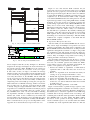
Figure 14 demonstrates a partial message segment of the
superframe management test. Readers are referred to [29] for
the complete test results captured by Wi-Analys. In Figure 14,
the Gateway tries to add a new superframe to the DUT using
command 965 in message number 41149. According to the
command payload, the ID of this superframe is 04. It has 1000
slots (0x03E8) and is set active (0x01). The DUT confirms
the success of this operation in message number 41152. It
sets the command response code as 0 and returns the number
of available slots in the superframe table which is 2. The test
Fig. 14.
A segment of the message sequence in the superframe management test case
continues to add more superframes to DUT in message number
41186 and 41232. The return message number 41235 from
the DUT shows that there is no more available slots for new
superframe. The message number 41275 attempts to add one
more superframe (ID = 07) and the DUT reports error status
in message 41282 with response code 0x41 which means the
superframe table in the DUT is full. After this test sequence,
the test then deletes the superframe 06 in message number
41322 using command 966 and the DUT responses to it in
message 41324 by showing that there is one slot available
in the superframe table. In message number 41367, the test
further tries to modify the existing superframe 04 by using
invalid number of slots (0x00) and the DUT reports error status
in message 41370 by presenting error code 0x43. In message
number 41429, the test tries to modify the number of slots on
superframe 02 from 1000 (0xE8) to 1 and the DUT confirms it
by sending message number 41434 back including the updated
information of superframe 02.
By injecting all possible configuration errors into the superframe table on the DUT, the superframe management test
conducts thorough exercises on the DUT’s superframe operations. The DUT passes this test only when all its responses
match the requirements of the WirelessHART standard.
C. Graph Routing and Source Routing Test Case
This subsection describes the network routing test which
focuses on verifying the DUT’s network layer behaviors. There
are two types of routing approaches adopted in WirelessHART
Device
Network Manager
Gateway
Access Point
Address
0xF980
0xF981
0x0001
Device
DUT
Virtual Device 1
Virtual Device 2
Address
0x0004
0x0005
0x0006
TABLE II
Device Addresses
standard: graph routing and source routing. WirelessHART
supports graph routing for robustness. A graph is directional
with only one sink node which is the destination of any
message. In graph routing, a message is forwarded by the
intermediate nodes to the next neighbor on the graph. Each
node is pre-configured with a set of forwarding neighbors of a
graph so that it can make the routing decision locally. The data
source simply associates a graph with the message and sends
it out. In this test case the DUT is configured with two graph
neighbors, VD1 and VD2, to send message to the Network
Manager and the Gateway. The device addresses used in this
and following test cases in Section VI-D and Section VI-E are
summarized in Table II.
In source routing the routing path is defined in the network
header of the message. A routing device simply forwards the
message to the next device in the path.
Fig. 15 shows the data request messages from the Network
Manager and the Gateway to the DUT, and the corresponding
response messages from the DUT.
• Packet 690 to 695 The Network Manager sends Command 64512 to the DUT with source routing, whose list
Fig. 15.
•
•
•
A segment of message sequence in the network routing test case
is AP, VD1, and DUT. The message is sent from the AP
to the VD1 within the virtual network (Packet 690). The
VD1 then forwards it to the DUT (Packet 697).
Packet 697 to 703 The DUT sends Command 64512
response back to the Network Manager using graph
0x01C1. The DUT selects the neighbor VD2 (Packet
697), who then forwards the message to the AP (Packet
702).
Packet 708 to 720 The Gateway sends Command 0 to the
DUT using graph 0x01B1. The AP selects the neighbor
VD2 (Packet 708), who then forwards to the DUT (Packet
719).
Packet 721 to 726 The DUT sends Command 0 response back to the Gateway using graph 0x01A1. The
DUT selects the neighbor VD1 (Packet 721), who then
forwards to the AP (Packet 725). Note this time the DUT
selects a different neighbor from the previous response to
Command 64512.
Fig. 16.
Fig. 17.
A segment of message sequence in the burst data test case
A segment of message sequence in the network maintenance test
E. Network Maintenance Test Case
D. Burst Data Test Case
The main function of a sensor in a process plant is to
periodically publish process value to the Host. In this test
case the DUT is preconfigured to publish Command 48 every
8 seconds. After the session and links with the Gateway is
configured, the DUT sends Command 799 to the Network
Manager asking for the bandwidth to publish (Packet 895 in
Fig. 16, forwarded in Packet 906). Since the Network Manager
has already configured it, it simply replies with the route
information in Packet 912 which is forwarded in Packet 917.
The DUT then sends out the first burst data in Packet 945,
forwarded in Packet 949. About 8 seconds later (Refer to the
second column Elapsed Time in Fig. 16) the next burst data is
sent out in Packet 971, forwarded in Packet 974. This periodic
data publishing will continue until the Gateway explicitly stops
it by sending corresponding commands to the DUT.
WirelessHART defines many ways to keep the mesh network healthy. For example, the device periodically sends
health reports to the Network Manager; it also reports to the
Network Manager if a neighbor is no longer communicating.
In this test case we shut down the VD1 after the DUT has
begun publishing data. Fig. 17 shows that the DUT reported
Command 788 (Path Down Alarm of the VD1) to the Network
Manager (Packet 5070 forwarded in Packet 5077). Note that
before the report the DUT sends message to the VD1 twice
in packets 5062 and 5069, neither of them is acknowledged.
Fig. 17 also shows the reporting of Command 780 (Report
Neighbor Health List) from the DUT in Packet 5057. It is
interesting to see that the VD2 forwarded it (Packet 5066)
after it has received a burst data from the DUT (Packet 5063).
Fig. 18 shows what happens after Command 788 is received.
The Network Manager sends a message to the DUT (Packet
approach is versatile in that any kind of tests can be conducted
with the same hardware but different test scripts. Our hybrid
approach of using radios to simulate environment interferences
makes mesh network development and deployment not only
more realistic but also more manageable. However, we should
point out that we do not claim that our approach will work
universally well for all application domains. In particular, the
following limitations are challenges to extending our approach
to other domains.
•
•
Fig. 18.
A segment of message sequence in the network reconfiguration
5080 forwarded in Packet 5083). The message contains: deleting the graph edge to the VD1 (Command 970), removing two
links to the VD1 (Command 968), and adding two extra links
to the VD2 (Command 967). The DUT responses it in Packet
5086 to notify the Network Manager that it is reconfigured
successfully.
F. Discussion on the Virtual Network Approach
The advantage of the virtual network approach we introduced in Wi-HTest is that it provides a way to scale up the
testbed setup and also offers very flexible functionality. In the
test cases demonstrated in previous sections, the DUT cannot
distinguish the difference between the test case from when it
interacts with a real WirelessHART mesh network of multiple
physical nodes, and the physical size of the Wi-HTest system
is strikingly small. The height of the upright Access Point with
the RF radio seen in Fig. 3 is just a little over 6 inches. With
our approach, we can develop a comprehensive ZigBee testbed
with the same amount of hardware as current Wi-HTest.
The next release for Wi-HTest will support 2 RF boards with
one Host. Although there is only one DUT, for some tests,
two antennae are needed. For example, in test case “TML401
Prioritization multiple simultaneous links”, the DUT will be
configured with two transmission links at the same timeslot.
Wi-HTest needs to listen on two different physical channels
on that timeslot to find out if the DUT has selected the correct
link for transmission. The synchronization of these RF boards
adds complexity to Wi-HTest. We have devoted quite a bit of
time just to get it right on the RF board. This vindicates in
some sense our strategy to reduce the number of antennae in
our approach.
While as many network nodes as possible can in principle
be simulated, physically the number of radios required is no
more than the maximum physical channels used by the mesh
simultaneously at any given time. The testbed based on our
•
Location Awareness. If message delay is used to locate
network nodes, our approach is limited as we cannot fake
different locations of the virtual devices. The limited simulation we can achieve is by changing the transmission
powers to simulate different virtual device locations or
mobile devices. However, for low power, low data rate,
and small area mesh networks, using message delay for
location awareness may be too hard to achieve.
Physical Channels. Although one radio for one physical
channel is reasonably sufficient for the process control
domain, we cannot realistically simulate a real world
environment in which multiple transmissions happen on
one channel. For example, two radios sufficiently far
apart may be able to use the same physical channel to
communicate different messages. However, it is probably
uncommon for the same physical channel to be used for
different communications in a small-area wireless mesh
network as is the case for industrial process automation,
for which the distances between any two nodes controlling the same devices are relatively small.
Total Timing Fidelity. Although it may be doable, it will
be difficult to reproduce in real time the sequence of all
the messages produced by a real mesh network.
VII. L ESSONS L EARNT
In this section, we share some useful lessons we learnt
during our design and development of Wi-HTest. We believe
that these experience would be valuable for those who are
interested in the inside of Wi-HTest or those who are going
to design and implement similar compliance testing suites for
other wireless standards.
•
•
An important step in the design phrase is to estimate
the hardware resources needed for specific development
purpose. For example, the memory size and the MCU
speed. Based on these resource requirements, the most
proper hardware platform available should be selected.
During our development, we had to switch from QE128
toolkit to JM128 board for larger memory size thus
suffered incremental development and unexpected delay.
Software architecture should be designed as flexible as
possible. This makes the new features of the software be
plugged in easily and seamlessly. In our initial design,
Wi-HTest is a sequential processing and only supports
single correspondent tests. To further support network and
application layer tests, we had to revise the architecture
of Wi-HTest to support virtual device/network and mul-
•
•
tiple DUTs. This revision introduced extra delay to our
development.
Timing is the most fundamental and critical part in WiHTest. All the communications in every layer are based
on the accurate timing information. We spent a huge
amount of time on achieving the accurate timing in the
10ms timeslot defined in the WirelessHART standards
and the network-wide synchronization.
For successful development, especially of the commercial
products in embedded systems, codes with built-in debugging functions are necessary. Without the supporting
debug functions, we have to play with the low-level codes
every time and the memory usage in the system is difficult
to be traced. This could make the debugging process
inefficient and timing-consuming.
VIII.
CONCLUSION
This paper presents the architecture of the Wi-HTest test
suite, a critical part of the compliance verification tool for realtime WirelessHART network. We also describe Wi-Analys and
the post process suite for capturing, analyzing the response
from the DUT and finally generating the compliance test
report. We describe the WirelessHART test specification and
the structure of the test scripts. Several representative test cases
on different communication layers are demonstrated to show
that Wi-HTest, together with Wi-Analys and the post test suite
provides an efficient test automation suite for WirelessHART
compliance test. The compliance verification deals with both
functional correctness as well as timing correctness. A critical
measurement is that the MAC layer acknowledgement for a
data request spanning a complex chain of events must not
exceed a 10ms time slot. This has been incorporated into our
test environment to guarantee the real-time communication of
the WirelessHART network. We also describe and the virtual
network approach that is applied in Wi-HTest to achieve
scalable testbed setup especially for testing network layer
behaviors, and discuss its advantages and limitations.
R EFERENCES
[1] Song Han, Jianping Song, Xiuming Zhu, Aloysius K. Mok, Deji
Chen, Mark Nixon, Wally Pratt, and Veena Gondhalekar, “Wi-HTest:
Compliance test suite for diagnosing devices in real-time WirelessHART
network,” in IEEE Real-Time and Embedded Technology and Applications Symposium, 2009, pp. 327–336.
[2] M.A.M. Vieira, D.C. da Silva Jr., C.N. Coelho Jr., and J.M. da Mata.,
“Survey on wireless sensor network devices,” in Emerging Technologies
and Factory Automation (ETFA’03), 2003.
[3] Jianping Song, Song Han, A.K. Mok, Deji Chen, M. Lucas, M. Nixon,
and W. Pratt, “WirelessHART: Applying wireless technology in realtime industrial process control,” Real-Time and Embedded Technology
and Applications Symposium, RTAS ’08. IEEE, pp. 377–386, April 2008.
[4] Dick Caro, Wireless Networks for Industrial Automation, ISA Press,
2004.
[5] Jr. Edgar H. Callaway and Edgar H. Callaway, Wireless Sensor
Networks: Architectures and Protocols, CRC Press, August 2003.
[6] Raymond Barrett Jose A. Gutierrez, Edgar H. Callaway, IEEE 802.15.4
Low-Rate Wireless Personal Area Networks: Enabling Wireless Sensor
Networks, IEEE, April 2003.
[7] I.F. Akyildiz, W. Su, Y. Sankarasubramaniam, and E. Cayirci, “A survey
on sensor networks,” in IEEE Communication Magazine, August 2002.
[8] Lakshman Krishnamurthy, Robert Adler, Phil Buonadonna, Jasmeet
Chhabra, Mick Flanigan, Nandakishore Kushalnagar, Lama Nachman,
and Mark Yarvis, “Design and deployment of industrial sensor networks:
experiences from a semiconductor plant and the north sea,” in SenSys
’05: Proceedings of the 3rd international conference on Embedded
networked sensor systems, New York, NY, USA, 2005, pp. 64–75, ACM.
[9] J. Song, S. Han, A. K. Mok, D. Chen, M. Lucas, and M. Nixon, “A study
of process data transmission scheduling in wireless mesh networks,” in
ISA EXPO Technical Conference, Oct. 2007.
[10] Jianping Song, Song Han, Xiuming Zhu, Al Mok, Deji Chen, and
Mark Nixon, “Demonstration of a complete WirelessHART network,”
in SenSys ’08: Proceedings of the 6rd international conference on
Embedded networked sensor systems (demo), 2008.
[11] Song Han, Jianping Song, Xiuming Zhu, Al Mok, Deji Chen, Mark
Nixon, Wally Pratt, and Veena Gondhalekar, “HTest-W: Testing suite
for diagnosing WirelessHART devices and networks,” in SenSys ’08:
Proceedings of the 6rd international conference on Embedded networked
sensor systems (poster), 2008.
[12] “WirelessHART,”
http://www.hartcomm.org/protocol/
wihart/wireless_technology.html.
[13] “Hart communication,” www.hartcomm.org/index.html.
[14] “Bluetooth,” www.bluetooth.com/bluetooth.
[15] “ZigBee Alliance,” www.zigbee.org/en/index.asp.
[16] “IEEE 802.11 Task Group,” grouper.ieee.org/groups/802/
11.
[17] “IEEE 802.15.4 WPAN Task Group,” www.ieee802.org/15/pub/
TG4.html.
[18] “ZigBee Automated Compliance Test,” www.seasolve.com.
[19] “Robustness tester for bluetooth,” www.codenomicon.com.
[20] “Wi-fi alliance,” www.wi-fi.org.
[21] “Azimuth systems inc.,” www.azimuthsystems.com.
[22] “CINT,” root.cern.ch/twiki/bin/view/ROOT/CINT.
[23] “TDMA-Mesh Test Specification,” HCF TEST-6, Revision 1.0.
[24] “Wi-Test Script Development User Manual,” HCF TEST-N, Revision
1.0.
[25] “DEMOJM Board,” http://www.pemicro.com/fixedlinks/
demoqetoolkit.cfm.
[26] “Freescale Coldfire,” www.freescale.com/coldfire.
[27] FIPS Publication 197, Advanced Encryption Standard (AES), U.S.
DoC/NIST, November 2001.
[28] “Device Join Test,” www.cs.utexas.edu/˜shan/join.pdf.
[29] “Superframe Management Test,” www.cs.utexas.edu/˜shan/
superframe.pdf.
A PPENDIX
Alg 1 Test Script for Device Join Test
TEST CONFIGURATION
{Equipment Setup}
Tester with 1 RF Interface (RF1).
One DUT with Maintenance Port connected to Tester.
Log RF and wired communications.
{Initialize test}
CALL InitializeTest ()
{Initialize the network}
GENERATE NETWORK (NetID=1, cm=all 15 channels)
GENERATE SESSION NetID.NetKey
{Initialize the Network Manager}
GENERATE SESSION NMUnicast
GENERATE SESSION-LIST SList
SList.ADD(NMUnicast)
{Generate initial Superframes}
GENERATE SUPERFRAME JoinFrame (250ms-1s)
GENERATE SUPERFRAME CommFrame (500ms-2s)
GENERATE SUPERFRAME-LIST SFList
SFList.ADD (JoinFrame)
SFList.ADD (CommFrame)
{Generate a placeholder for DUT}
GENERATE DEVICE NicknameDUT
GENERATE SESSION JoinKey
SList.ADD(JoinKey)
{Generate an initial route and graph}
GENERATE ROUTE Route1
GENERATE GRAPH Graph1 (0x0100-0xFFFF)
GENERATE LINK FOR JoinFrame:
LinkJF1 (DUT to Tester)
LinkJF2 (Tester to DUT)
GENERATE LINK-LIST Links
Links.ADD(LinkJF1)
Links.ADD(LinkJF2)
{Configure the tester ”RF1” with setup 1A}
CONFIGURE RF1 with JoinFrame, NetID, NetKey and Gateway Address
TEST BODY
{Find and reset the device}
CALL IdentifyDevice (TML102.A.001)
CALL ResetDevice (TML102.A.002)
{Provision the device with a NetID}
CALL ProvisionDevice(NetID, JoinKey, TML102.A.003)
{Set advertise to a occur at a random number of frames in time send force
join}
GENERATE NUMBER NumFrames(1-4)
SET RF1.AdvertiseInterval = (CommFrame.NumberOfSlots * NumFrames)
SET ShedTime = RF1.AdvertiseInterval *15
SEND Cmd 771 ( ”Join Now”, ShedTime)
IF ResponseCode == 0
VerifyResponseAndByteCount (0, 5+2, TML102.A.004a)
ELSE
VerifyResponseAndByteCount (8, 5+2, TML102.A.004b)
SET ShedTime = shed-time
END IF
IF (join-mode != ”Join Now”)
Test Result is FAIL
IF (shed-time != ShedTime)
Test Result is FAIL
{Monitor the progress}
SEND Cmd 769
CALL VerifyResponseAndByteCount (0, 14+2, TML102.A.007)
IF Wireless-Operation-Mode != ”Active Search”
Test Result is FAIL
ENABLE RF1
{Assimilate the device and analyze the Join Request}
CALL PollCmd769 (0x001F, 0xFFDF, ShedTime, 1, TML102.A.009.x)
SET NPDU = SessionKey, JoinKey, NMShortAddress, -1, -1,
DUTUniqueID+HCF OUI, Graph1
ParseNetworkPDU (NPDU, TML102.020)
RECORD Join-Nonce for device NicknameDUT
IF Transport-Byte.Acknowledged bit set
THEN Test Result is FAIL
IF Transport-Byte.Response bit is clear
THEN Test Result is FAIL
IF Transport-Byte.Broadcast bit is set
THEN Test Result is FAIL
{Parse Payload: must be a join request (Cmd 0 + Cmd 20 + Cmd 787
Responses.}
SET cmds[] to 0,20,787
ParseAppPDU(3, cmds , cmdPDU[ ], TML102.A.012)
IF cmdPDU[0].data != Cmd 0 data from IdentifyDevice()
THEN Test Result is FAIL
IF cmdPDU[1].data != LONG-TAG
THEN Test Result is FAIL
CALL ValidateCmd787Rsp( CmdPDU[2], GW-Nickname, TML102.A.015)
{Write DUT network key and nickname address and session with NM as
the Join Response CREATE PAYLOAD ”Join Response” with Cmd 961,
962, 963}
CREATE PAYLOAD ”Join Response” with Cmd 961, 962, 963
SET Cmd961.Network-Key to NetKey
SET Cmd961.ASN to 0
SET Cmd962.Nickname to NicknameDUT
{Send a full length Cmd 963}
NMUnicast.BuildWriteSessionCmd (Cmd963, FALSE)
{Send these as a join response to the DUT (cmds 961, 962, 963)}
CREATE NLPDU from PAYLOAD using JoinKey and Join-Nonce
XMIT NLPDU
{Wait for reply}
SET Timeout = 5 * JoinFrame length
CALL PollCmd769 (0x009F, 0xFFDF, Timeout, 1, TML102.A.016.x)
{Next, analyze the received packet NLPDU (Join Request) Short NM
Address, Short DUT address}
SET NPDU = SessionKey, JoinKey, NMShortAddress, -1, NicknameDUT,
-1, Graph1
ParseNetworkPDU (NPDU, TML102.A.020)
IF Transport-Byte.Acknowledged bit set
THEN Test Result is FAIL
IF Transport-Byte.Response bit is clear
THEN Test Result is FAIL
IF Transport-Byte.Broadcast bit is set
THEN Test Result is FAIL
{Parse the Response: must be Cmd 961 + Cmd 962 + Cmd 963 Responses.}
SET cmds[] to 961, 962, 963
ParseAppPDU(3, cmds , cmdPDU[ ], TML102.A.018)
IF cmdPDU[0].Network-Key != NetKey
THEN Test Result is FAIL
IF cmdPDU[0].ASN != 0
THEN Test Result is FAIL
IF cmdPDU[1].Nickname != NicknameDUT
THEN Test Result is FAIL
NMUnicast.ParseWriteSessionRsp(cmdPDU[2],
TML102.A.022)
SList,
{Check device nickname address via maintenance port}
SEND Cmd 781
CALL VerifyResponseAndByteCount (0, 4, TML102.A.023)
IF Cmd781.Nickname != NicknameDUT
THEN Test Result is FAIL
END TEST CASE
FALSE,
0,