1
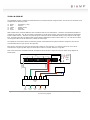
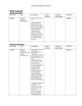
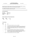
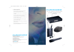
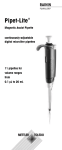
Interfacing Clockaudio® microphones with the Logic Box INTRODUCTION One popular application for the Logic Box is to interface with conferencing microphones that feature mute switches and LED indicators, and Clockaudio is a leading manufacturer of such microphones. This application note describes how to physically connect some of Clockaudio’s most popular microphone accessories to a Biamp Logic Box. Additionally, the final section provides some tips on how to program the Logic Box to make the LED’s and mute switches behave in different ways. A BRIEF NOTE ABOUT POWER A common misconception about the Logic Box is that it is capable of supplying the DC power required to light up any LED’s connected to it. While the Logic Box does generate some voltage to facilitate the detection of contact closures and other functions, it does not supply any appreciable current to power external devices. In the first two examples below, an external DC power supply is used to power the LED’s. This power supply is not included with either the Clockaudio microphones or the Biamp Logic Box. CH32 LITETOUCH HALO WIRING The Clockaudio CH32 Litetouch is a dual-color halo ring and switch combination which is used in concert with various through-table microphones. The CH32’s 5-conductor cable tail is comprised of the following colors: Red Green Yellow Brown Blue - Red LED Green LED Switch contact DC Voltage + Ground Older models of the CH32 had different color conductors than the ones listed above. Check the included documentation to confirm the color code. Each LED will connect to a separate logic output on the Logic Box, and the switch contact will connect to a logic input. Therefore, each CH32 uses 3 I/O terminals on the Logic box, meaning that a maximum of six CH32’s can be connected to one Logic Box. For its DC power, the CH32 can use either a 12V or 24V power supply, and each CH32 consumes 40mA of current. When using a 12V power supply the LED’s can be connected directly to the Logic Box, however when using a 24V power supply the LED’s must be connected in series with a 300-ohm 1-watt resistor. Figure 1 shows how to wire the CH32 to a Logic Box using either a 12V or 24V power supply: Remote Control Bus 12~24VDC @ 600mW 16 15 14 13 12 11 10 9 OUTPUTS 8 7 6 5 4 3 2 1 +- To Logic Box logic inputs 300Ω 1W 300Ω 1W Resistors required only if using a 24V power supply Logic Box term hi lo To Logic Box logic outputs 20 19 18 17 power Logic inputs are activated via contact-closure or 5V TTL Logic outputs are open-collector (40V / 500mA max. per output) INPUTS 5 6 7 8 9 10 11 12 13 14 15 16 17 18 19 20 status 1 2 3 4 12V or 24V DC Power Supply - + Clockaudio CH32 Switch (Yellow) Red LED (Red) Green LED (Green) Ground (Blue) DC + (Brown) Figure 1 - CH32 wiring diagram. Note that the 300-ohm resistors are only necessary when using a 24VDC power supply. When using a 12VDC power supply, the logic box outputs can be directly connected to the CH32. SM80S The Clockaudio SM80S is a table-mounted shock mount with a switch and a single-color LED. The SM80S’s 5-conductor tail is comprised of the following colors: Brown Black Orange Red Blue - DC Voltage + Ground Switch contact (normally closed) Switch contact (normally open) Switch contact ground The SM80S works a bit differently than the CH32, in that the LED is turned on and off by applying and removing the DC voltage. This is accomplished by using the Logic Box’s logic outputs to connect and disconnect the power supply’s path to ground. Another difference is the option of a normally closed or a normally open switch contact. Only one or the other needs to be used, and the example below in Figure 3 uses the normally closed option. The LED on the SM80S can use a 5V, 12V, or 24V power supply. There is a small jumper on the SM80S which must be correctly set to correspond to the DC voltage being used. The jumper is applied to a pair of pins on the SM80S’s circuit board. Apply the jumper to the outermost pair of pins (i.e. closest to the outer edge of the circuit board) when using a 24V power supply; apply the jumper to the middle pair of pins when using a 12V power supply, and apply the jumper to the innermost pair of pins when using a 5V power supply. Each SM80S consumes one logic input and one logic output on the Logic Box, so up to 10 SM80S’s can be connected to a single Logic Box. Figure 2 shows how to connect an SM80S shock mount to a Logic Box. Remote Control Bus 12~24VDC @ 600mW 12 11 10 9 OUTPUTS 8 7 6 5 4 3 2 1 +- Logic Box term hi lo To Logic Box logic output 16 15 14 13 To Logic Box logic input 20 19 18 17 power Logic inputs are activated via contact-closure or 5V TTL Logic outputs are open-collector (40V / 500mA max. per output) INPUTS 5 6 7 8 9 10 11 12 13 14 15 16 17 18 19 20 status 1 2 3 4 DC power supply (5V, 12V, or 24V) - + Clockaudio SM80S Switch NO (Red) Switch NC Switch Ground (Orange) (Blue) Ground (Black) DC + (Brown) Figure 2 - SM80S wiring detail. Note that only one of either the normally closed or normally open switch contacts will be used. This example uses the normally closed switch contact, which is generally preferred for Logic Box applications. S135 The Clockaudio S135 is a microphone desk stand with a mute switch and a single-color LED. The desk stand has a 5-pin XLR connector, with the following functions assigned to each pin: Pin Pin Pin Pin Pin 1 2 3 4 5 - Ground LED contact (control input) Audio (-) Switch contact (control output) Audio (+) The S135 operates in a similar way as the CH32, in that its LED is controlled by a contact closure rather than switching its power voltage on and off. However, the S135 is unique in that it uses the microphone’s phantom power to light the LED rather than an external power supply. Therefore, no external power supply is required for use with the S135. Each S135 uses one logic input and one logic output on the Logic Box, therefore up to 10 S135’s can be connected to a single Logic Box. Figure 3 shows how to connect an S135 to a Logic Box. + - G Remote Control Bus 12~24VDC @ 600mW status 1 2 3 4 Logic inputs are activated via contact-closure or 5V TTL Logic outputs are open-collector (40V / 500mA max. per output) INPUTS 5 6 7 8 9 10 11 12 13 14 15 16 17 18 19 20 12 11 10 9 OUTPUTS 8 7 6 5 4 3 2 1 +- hi lo Logic Box term To Logic Box logic output 16 15 14 13 To Logic Box logic input 20 19 18 17 power Audio Input (AudiaFLEX or Nexia) Audio + (Pin 5) Clockaudio S135 5-pin XLR 5 1 4 Switch Out (Pin 4) 3 Ground (Pin 1) 2 LED contact (Pin 2) Audio (Pin 3) Figure 3 - S135 wiring detail. No power supply is required to power the LED. The S135 also has various options to change the behavior of the switch and LED. To set the options, hold down the mute button while applying power to the mic (either by plugging the mic cable in, or by switching on phantom power). The LED will flash for 2 seconds to indicate that you are in setup mode. Then, press the switch 1-4 times (the interval between presses must be less than 1 second), depending on which option you want to set (see Figure 4). Once you have selected the option you want to change, the LED will blink once for mode one or twice for mode two to indicate which mode that option is currently set to. Then, you can press the switch either once or twice to set the option to the desired mode. See the table in Figure 4 below for the four available options and their modes. After setting an option, the LED blinks for 2 seconds again, indicating that it is ready for you to select another option. Otherwise, if you don’t press the switch for longer than 5 seconds, the unit will exit setup mode and resume normal operation. Option Mode 1 (Press once) Mode 2 (Press twice) 1 - Momentary/Latching Switch Momentary Latching 2 - Normally Off / Normally On Normally Off (Push to talk) Normally On (Push to mute) Tone Off Tone On Local Mute (S135 mutes the mic signal) Remote Mute (Audia/Nexia mutes the mic signal) 3 - Activation Tone Off/On 4 - Local Mute / Remote Mute Figure 4 - Table showing the four options which can be set in an S135. Each option can be set to one of two modes. For instance, to set the S135 to Remote Mute mode, first press the button four times to select option 4, then press the button twice to select mode 2. TS-001 & CS2S-RF The Clockaudio TS-001 is a table-mounted electronic touch switch with red and green LED’s. The TS-001’s 5-conductor tail is comprised of the following colors: Brown Blue Yellow Red Green - DC Voltage (+12V) Ground Switch contact Red LED Green LED Older models of the CH32 had different color conductors than the ones listed above. Check the included documentation to confirm the color code. The TS-001 switch is powered by a 12V DC power supply, and its dual-color LED’s are triggered by simple contact closures. Therefore, the pink and green conductors can be connected directly to logic outputs on the Logic Box. Connecting the LED’s to different logic outputs allows independent control of which LED is on. You can also turn both red and green LED’s on at the same time, creating an amber light. The capacitive touch switch causes a momentary contact closure between the yellow conductor and ground, and can be connected directly to a logic input on the Logic Box. Each TS-001 consumes one logic input and two logic outputs on the Logic Box, so a maximum of six TS-001’s can be connected to a single Logic Box. Figure 5 shows how to connect a TS-001 switch to a Logic Box. Also of note is that the Clockaudio CS2S-RF microphone can be wired to a Logic Box using the same wiring diagram as shown below. 16 15 14 13 12 11 10 9 OUTPUTS 8 7 6 5 4 3 2 1 To Logic Box logic input To Logic Box logic outputs 20 19 18 17 +- power Remote Control Bus 12~24VDC @ 600mW status 1 2 3 4 Logic inputs are activated via contact-closure or 5V TTL Logic outputs are open-collector (40V / 500mA max. per output) INPUTS 5 6 7 8 9 10 11 12 13 14 15 16 17 18 19 20 Logic Box term hi lo 12V DC power supply + - Clockaudio TS-001 Switch (Yellow) Green LED (Green) Red LED (Red) +12VDC (Brown) Ground (Blue) Figure 5 - TS-001 wiring detail. The switch/LED connections from a Clockaudio CS2S-RF microphone can be wired to a Logic Box using the same wiring diagram. LOGIC BOX PROGRAMMING Now that the microphone is physically connected to the Logic Box, it’s time to program it. To program the Logic Box, simply add a Logic Box block to the Audia™ or Nexia™ file for the system. The nodes on the top of the Logic Box block represent the physical logic outputs on the device, and the nodes on the bottom of the Logic Box block represent the physical logic inputs on the device. There are only two states that a logic signal can be: high or low (on or off, 1 or 0). The sections below describe how these two logic states interact with the Logic Box’s logic inputs and outputs. Figure 6 - Logic Box block. Logic Outputs The logic outputs on a Logic Box are what drive the LED’s on the microphones. By sending a logic signal to the top node of a Logic Box block corresponding to the logic output that you wish to control, you can change whether that logic output is creating a short circuit to ground or an open circuit to ground. Sending a low logic signal results in a short circuit, and sending a high logic signal results in an open circuit. Logic Inputs The logic inputs on a Logic Box are what detect contact closures from the mute switches on the microphones. When the switch connected to a logic input is closed (shorted to ground), a low logic signal is generated at the corresponding bottom node of the Logic Box block. When the switch is open to ground, a high logic signal is generated. This means that logic inputs are “normally high”; that is, if there is nothing connected to a logic input, it will be generating a high logic signal. LOGIC GATES Logic gates can be used to transform logic signals in various ways. To insert a logic gate into your configuration file, select Logic Gate from the Control menu on the device toolbar, click in your file to insert it, and then select the type of logic gate you want to use. It’s not in the scope of this document to describe all logic gates in detail, but below are a few that are commonly used with Logic Boxes. For details on other logic gates, consult the Help system in the Audia or Nexia software or the Audia/Nexia user manual. NOT Gate A NOT gate is a simple logic gate which inverts the logic signal that it is receiving. In other words, if you send a low logic signal to the input of a NOT gate, it will output a high logic signal, and vice versa. For instance, if you connect a contact closure button to a logic input on a Logic Box, and that button is normally open (i.e. it creates a short circuit when the button is pushed), then the Logic Box block will be generating a high logic signal when the button is not pushed and the logic signal will go low when the button is pushed. However, you may want the logic signal to be low when the button is not pushed, and high when it is pushed. In this case, a NOT gate is the solution. Flip Flop Gate A Flip Flop gate is used to transform a momentary logic pulse signal into a latching (or toggle) logic signal. The Flip Flop gate works by toggling its output signal whenever its receives a low-to-high logic transition on its input. It doesn’t do anything when it receives a high-to-low logic transition. So, the first time it receives a low-to-high logic transition at its input, it will send a high logic signal out of its output; the next time it receives a low-high-logic transition, it will start sending a low logic signal out of its output. Logic State A Logic State block is a logic block which generates a logic signal. It will generate a low logic signal if its “Set” button is disengaged, and it will generate a high logic signal its “Set” button is engaged. A common use for a Logic State block is to generate a logic signal and send it directly to the top nodes of a Logic Box block (logic outputs). This would allow you to manually control whether a logic output is opened or closed. Logic Meter Logic Meters are a very useful troubleshooting tool when programming a Logic Box, because they allow you to view the state of a logic signal at any point in your logic circuit. You can find Logic Meters in the “Meters” menu in the device toolbar. Figure 7 - Example logic circuit incorporating the Logic State, NOT gate, Logic Box, Flip Flop gate, and Logic Meter. This circuit could be used to test a switch and an LED connected to logic input 1 and logic output 1 on the Logic Box. EXAMPLE APPLICATIONS Contact closure button recalls preset A simple, common application is to connect a contact closure button to a Logic Box, and recall a preset whenever that button is pressed. The key to making this happen is the Remote Preset block. This block is triggered by a logic signal and recalls a preset whenever it sees a low-to-high logic transition. To load a preset into a Remote Preset block, open the block, right-click on the preset button and select “Assign Preset”. Then, choose the desired preset from the drop-down menu. If your contact closure button is normally open, using a NOT gate as in Figure 8 will ensure that the preset gets recalled when you push the button down, not when you let it up. Contact closure button sends a serial string Also in Figure 8, notice that the same contact closure button is connected to a Command String block. A Command String block operates the same way as a Remote Preset block, but instead of recalling a preset, it sends a custom string out of the RS232 port on the unit. This is useful for notifying a control system of an event that has happened. You can also use a Command String block to send hex characters by preceding the two-digit hex code with a tilde character (~). Figure 8 - Contact closure button recalls a preset and sends a serial string. Momentary contact closure mutes and unmutes a mic The Mute Control block has the capability of controlling its mute buttons via logic signals. When dropping the Mute Button block into your file, ensure that the “Control Inputs” check box is checked. This will enable logic inputs on the block. If the logic input for a channel receives a high logic signal, it will mute the mic. If it receives a low logic signal, it will unmute the mic. Keep in mind that all of the mic accessories discussed earlier in this document have momentary mute switches. That is, the switch is closed while you’re pushing it down and open when you let it up. If you connected this switch to a Logic Box, and then connected a logic signal from the Logic Box directly to the Mute Control block, it would only unmute the mic when you push the button down. If you connected the Logic Box through a NOT gate and then to the Mute Control block, it would mute the mic only while the button is held down. More commonly, users expect a toggle functionality where the mic will toggle on and off each time they press the button. They might also expect the LED on the mic to turn on when the mic is live and turn off when the mic is muted. The logic circuit in Figure 9 shows a common way to make this happen. The Flip Flop gate transforms the momentary logic signal to a latching signal, and its output controls both the muting of the microphone and the state of the LED. Figure 9 - Using a momentary button to toggle the mute state of a mic, as well as its LED state. Using multiple Logic Boxes in a system If the application requires a lot of microphones, you may be required to use multiple logic boxes to connect all of them. In this case, it’s important to know how to identify each Logic Box. In each Logic Box block, there is a number in the top-left corner and another number in the bottom-right corner. (If these numbers aren’t there, go to Tools— >Options—>Display tab and select “Display device assignment”.) The number in the top-right corner tells you which unit the Logic Box is assigned to. This must correspond to the unit to which the Logic Box is physically connected. If it is not set to the correct unit, open the Properties sheet on the Logic Box block, go to the DSP Attributes tab, select the correct unit under “Allocated to Unit”, and select “Yes” under “Fixed In Unit” to ensure that the compiler doesn’t change which unit it’s allocated to the next time you compile. The number in the bottom-right corner is the ID of the Logic Box itself, and it allows you to identify each Logic Box individually. This number will also show up in the RCB tab of the Equipment Table (Tools—>Equipment Table), and it will allow you to assign the correct serial number to the correct Logic Box. Figure 10 - Two Logic Boxes connected to one unit, one is ID 1 and the other is ID 2. The partial window above is the RCB tab of the Equipment Table.