1
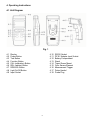
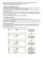
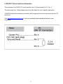
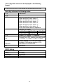
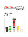
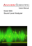
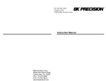
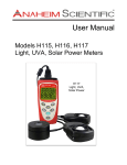
INSTRUCTION MANUAL Model: H500 RGB Color Analyzer Table of Content 1. Product Introduction ………………………………………… 3 1-1 Features ………………….………………………… 3 1-2 Applications ……………………………………...… 3 2. Safety Information …………………………………………… 4 2-1 Cautions ………………………………..………..… 4 2-2 Safety Symbols ………………………..…..……… 4 3. Specifications ……………………………………...…………. 5 4. Operation Instructions ……………………………………… 4-1 Unit Diagram ……………………………………… 4-2 Non Light Emitting Sample Measurements …... 4-3 Light Emitting Sample Measurements ………… 4-4 RGB & HSL Measurements ……..……………… 4-5 HSL Measurements …………………………….. 4-6 REL (Relative) Measurements .………………… 6 6 7 7 7 7 8 5. Calibration Procedure ……………………………………… 8 6. RS232 PC Serial Interface Information …………………. 9 7. Maintenance ………………………………………………….. 11 7-1 Battery Replacement ……………………………... 11 7-2 Trouble Shooting ………………………………….. 11 8. Service Information …………………………………………. 12 9. Warranty Information ………………………………………. 13 To see all available accessories and downloadable software, please visit www.anaheimscientific.com 1. Product Introduction Congratulation on your purchase of this Anaheim Scientific RGB Color Analyzer with HSL measuring capabilities. The H500 is equipped with an external sensor probe having a 45°/0° color measuring geometry. It is designed around a microprocessor technology that uses a spectral analysis method to determine the color of the area under test. The model H500 has excellent repeatability due to the spectroscopic analysis technique used. 1-1 Features Measure both RGB and HSL levels Easy to use Relative (REL) feature allows the comparison of to color samples Two year warranty 1-2 Applications Check color levels of Plastics, Textiles, Paper, Paints and Leathers Quality control in production and manufacturing Comparisons of color samples against color standards Check reference color values of CRTs, LCD monitors and light lamps 3 2. Safety Information Read the following safety information carefully before attempting to operate or service the meter. Only qualified personnel should perform repairs or servicing not covered in this manual. 2-1 Cautions! DO NOT submerge the products mentioned in this manual in water or any other types of liquids. This product is not designed for use in medical applications. The product can only be used to measure body temperature simply for reference. 2-2 Safety Symbols Dangerous, refer to this manual before using the meter. Conforms to requirements of European Union and European Fare Trade Association (EFTA). Battery level is low. Don’t dispose this product as unsorted municipal waste. This instrument conforms to the following standards: EN61326: Electrical equipment for measurement, control and laboratory use. IEC61000-4-2: Electrostatic discharge immunity test. IEC61000-4-3: Radiated, radio-frequency, electromagnetic field immunity test. IEC61000-4-8: Power frequency magnetic field immunity test. 4 3. Specifications Display Measuring Geometry Spectral Range Light Source Measuring Principle Color Sensors Measurements Repeatability LCD size: 2.3 x 1.3" (59 x 34mm) 45°/0° - Circular illumination at 45°, measurement at 0° 400nm to 700nm Two white LEDs - For non light emitting sample measurements such as textiles or paper, a defined light source illuminates the sample and reflected surface light is spectrometrically analyzed. - For light emitting sample measurements such as CRT or LCD, the light source from the sample is spectrometrically analyzed directly. Three color photo transistors. One for all three Red, Blue & Green colors. RGB Value R (Red) value : 0 to 1023 G (Green) value: 0 to 1023 B (Blue) value: 0 to 1023 HSL Value H (Hue) value: 0 to 1.000 S (Saturation) value: 0 to 1.000 L (Luminance) value: 0 to 1.000 Specified after the instrument is calibrated and measurement is repeated on the same sample tested ten times within two minutes. R (Red) Value <4 G (Green) Value <4 B (Blue) Value <4 H (Hue) Value < 0.02 S (Saturation) Value < 0.02 L (Luminance) Value < 0.02 Measurement Sample Material Types Type 1 = Non light emitting material such as Textiles, Paint etc… Type 2 = Light emitting material such as CRT, LCD, Lamp etc… Important Note: The H500 is designed for measuring type 1 materials. Type 2 materials are for reference only, any accuracies or stated capabilities do not apply to type 2 materials. Auto Power Off Approximately after three minutes Operating Temp. 32° to 122°F (0° to 50°C) @ <80% RH Power Supply DC 9V Battery (type 006P, MN1604(PP3) or equivalent), 6.4mA standby / 32mA measurement (AC Adapter not included) Weight (approx.) 1.05 lb (478g) Dimensions (approx.) Main instrument: 8 x 3 x 1.5" (203 x 76 x 38mm) Sensor probe: 6.3 x 3.6 x 1.8" (160 x 92 x 45mm) Included Accessories Instruction manual, calibration card, battery, carrying case Specifications and information is subject to change without notice. For the most current and up-to-date product information please visit www.anaheimscientific.com 5 4. Operating Instructions 4-1 Unit Diagram Fig. 1 4-1 4-2 4-3 4-4 4-5 4-6 4-7 4-8 4-9 Display Power Button Test Button Function Button CAL (calibration) Button REL (relative) Button RGB/HSL Button Light On/Off Button Input Socket 4-10 4-11 4-12 4-13 4-14 4-15 4-16 4-17 4-18 6 RS232 Socket DC 9V Adapter Input Socket Battery Compartment Stand Tripod Screw Mount Color Sensor Element Measurement Trigger Probe Handel Probe Plug 4-2 Non-Light Emitting Sample Measurement This mode of operation is design for use on materials that do not emit light. The H500 is primarily designed to work on non-light emitting materials. 1. Connect the “Probe Plug” (4-17, Fig.1) to the “Input Socket” (4-9, Fig.1). 2. Power the meter on by pressing the “Power Button” (4-2, Fig.1). The display will show zero values. 3. Use the “Probe Handel” (4-17, Fig.1) to position the “Color Sensor Element” (4-15, Fig. 1) over the color to be measured. Ensure that the front of the color sensor head is flush with the surface. 4. Follow the appropriate steps that appear in sections 4-4 through 4-6 to continue your measurements. 4-3 Light Emitting Sample Measurements This mode of operation is design for use on materials that emit light (such as a LCD or CRT). The H500 is primarily designed to work on non-light emitting materials. Any values measured with this instrument in this mode should be considered estimations and are not actual values. 1. Connect the “Probe Plug” (4-17, Fig.1) to the “Input Socket” (4-9, Fig.1). 2. Power the meter on by pressing the “Power Button” (4-2, Fig.1). The display will show zero values. 3. Press the “Light On/Off Button” (4-8, Fig. 1). 4. Use the “Probe Handel” (4-17, Fig.1) to position the “Color Sensor Element” (4-15, Fig. 1) over the color to be measured. Ensure that the front of the color sensor head is flush with the surface. 5. If the LEDs near the “Color Sensor Element” (4-15, Fig. 1) turn on then the meter is set to still measure non-light emitting samples. Press the “Light On/Off Button” (4-8, Fig. 1) to turn off the LEDs. 6. Follow the appropriate steps that appear in sections 4-4 through 4-6 to continue your measurements. 4-4 RGB Measurements 1. For RGB measurements follow steps from section 4-2 and then press the “Measurement Trigger” (4-16, Fig. 1) or the “Test Button” (4-3, Fig. 1). 2. Continue to hold the “Color Sensor Element” (4-15, Fig. 1) in place while the meter makes its measurement. During the measurement you will see the “Mesu” marker on the top of the LCD. The measurement process takes approximately 5 seconds. 3. After the measurement you the RGB values on the LCD and the “Mesu” marker on the LCD will disappear. 4-5 HSL Measurements 1. For HSL measurements follow steps from section 4-4, then press the “RGB/HSL Button” (4-7, Fig. 1). This will display the HSL values. A separate measurement is not necessary. 2. You toggle between values by pressing the “RGB/HSL Button” (4-7, Fig. 1). HSL Considerations: The HSL color is more closely approximates how the human eye distinguishes a color compared to the common RGB color value. 7 Hue is what distinguishes on color from another. You can think of Hue a specific color. Saturation is how much color or the purity of the color is present. Luminance is how bright or intense the color is. 4-6 REL (Relative) Measurements After making a measurement it is possible to subtract the measured values from the display to allow you to easily measure the difference of two color samples. 1. After a measurement has been made, press the “REL Button” (4-6, Fig.1) and the LCD should display all zeros. 2. Now perform your measurement on the new sample. The resulting displayed values will be the difference between the two colors. The values will be flashing on the screen to notify you that you are reading REL values. 3. Press the “REL Button” (4-6, Fig.1) to exit the REL mode. 5. Calibration Procedure 1. Set meter to be used to measure RGB by following steps 4-2 and 4-4. 2. Lay the White Color Calibration Card included with your H500 on to a flat surface so you will have access to the White Card. 3. Place the “Color Sensor Element” (4-15, Fig. 1) over the White Card making sure that it is flush with the card surface. 4. Simultaneously press the “Function Button” (4-4, Fig. 1) and the “CAL Button” (4-5, Fig. 1) then release the buttons to commence calibration. It is important to keep the probe in place during the entire process. 5. You will see the following sequence displayed on the LCD. 8 6. RS232 PC Serial Interface Information This instrument has RS232 PC serial interface via a 3.5 mm terminal (4-12, Fig. 1). The data output is a 16 digit stream which can be utilized for user's specific application. A RS232 lead with the following connection will be required to link the instrument with the PC serial port. Visit www.anaheimscientific.com to see any available downloadable software for your instrument. 9 The 16 digit data stream will be displayed in the following format: D15 D14 D13 D12 D11 D10 D9 D8 D7 D6 D5 D4 D3 D2 D1D0 Each digit indicates the following status: D15 Start Word D14 4 D13 When send the R color value = 1 When send the G color value = 2 When send the B color value = 3 When send the H color value = 4 When send the S color value = 5 When send the L color value = 6 Note: Send these values in sequence D12 & D11 Indicator for Display R = 70 G = 71 B = 72 H = 42 S = 73 L = 99 D10 Polarity: 0 = Positive / 1 = Negative D9 Decimal Point (DP), position from right to left 0 = No DP, 1 = 1 DP, 2 = 2 DP, 3 = 3 DP D8 to D1 D0 Display reading, D1 = LSD, D8 = MSD Example: If the display reading is 1234, then D8 to D1 is: 00001234 End Word RS232 Setting Baud Rate Parity Data bit # Stop bit 9600 No Parity 8 Data bits 1 Stop bit 10 7. Maintenance 7-1 Battery Replacement 1. When the LCD display shows the “ ” low battery symbol, It is necessary to replace the battery. The specifications listed for this instrument do not apply when the low battery symbol is displayed. 2. Open the “Battery Compartment” (4-12, Fig. 1) by first loosening the single battery cover screw. 3. Replace the batteries with “good” batteries noting the correct polarity. Replace “Battery Compartment” (4-12, Fig. 1) and battery cover screw. Ensure the cover is securely fastened. 7-2 Trouble Shooting Low Value Measurements: 1. If during a “Non-Light Emitting Sample Measurement” the meter displays unusually low RGB values, check and make sure both LEDs are turning on when you press the “Measurement Trigger” (4-16, Fig. 1) or the “Test Button” (4-3, Fig. 1). 2. If neither LEDs turn on follow steps from section 4-2. 3. If only one LED turns on then the unit needs repair. Unit will not power on or buttons not performing specified functions: 1. Replace the batteries following step from 7-1.. 2. Perform calibration process from section 5. 11 8. Service Inform ation W arranty Service: Please return the product in the original packaging with proof of purchase to the address below. Clearly state in writing the performance problem and return any leads, probes, connectors and accessories that you are using with the device. Non-W arranty Service: Return the product in the original packaging to the address below. Clearly state in writing the performance problem and return any leads, probes, connectors and accessories that you are using with the device. Customers not on open account must include payment in the form of a money order or credit card. For the most current repair charges please visit www.anaheimscientific.com and click on “service/repair”. Return all merchandise to Anaheim Scientific with pre-paid shipping. The flat-rate repair charge for Non-Warranty Service does not include return shipping. Return shipping to locations in North American is included for Warranty Service only. For overnight shipments and nonNorth American shipping fees please contact Anaheim Scientific. Anaheim Scientific 22820 Savi Ranch Parkway Yorba Linda, CA 92887 www.anaheimscientific.com 714-921-9095 Include with the returned instrum ent your com plete return shipping address, contact nam e, phone num ber and description of problem . 12 9. Lim ited Two-Year W arranty Anaheim Scientific warrants to the original purchaser that its products and the component parts thereof, will be free from defects in workmanship and materials for a period of two years from date of purchase from an authorized Anaheim Scientific distributor. Anaheim Scientific will, without charge, repair or replace, at its option, defective product or component parts. Returned product must be accompanied by proof of the purchase date in the form of a sales receipt. To obtain warranty coverage in the U.S.A., this product must be registered by completing the warranty registration form on www.anaheimscientific.com within fifteen (15) days of purchase. Exclusions: This warranty does not apply in the event of m isuse or abuse of the product or as a result of unauthorized alterations or repairs. The warranty is void if the serial num ber is altered, defaced or rem oved. Anaheim Scientific shall not be liable for any consequential damages, including without limitation damages resulting from loss of use. Some states do not allow limitations of incidental or consequential damages. So the above limitation or exclusion may not apply to you. This warranty gives you specific rights and you may have other rights, which vary from state-to-state. Anaheim Scientific 22820 Savi Ranch Parkway Yorba Linda, CA 92887 www.anaheimscientific.com 714-921-9095 13 Anaheim Scientific 22820 Savi Ranch Parkway Yorba Linda, CA 92887 U.S.A. http://www.anaheimscientific.com Printed in Taiwan / Ver. 1.1/081209 © 2009 Anaheim Scientific Corporation